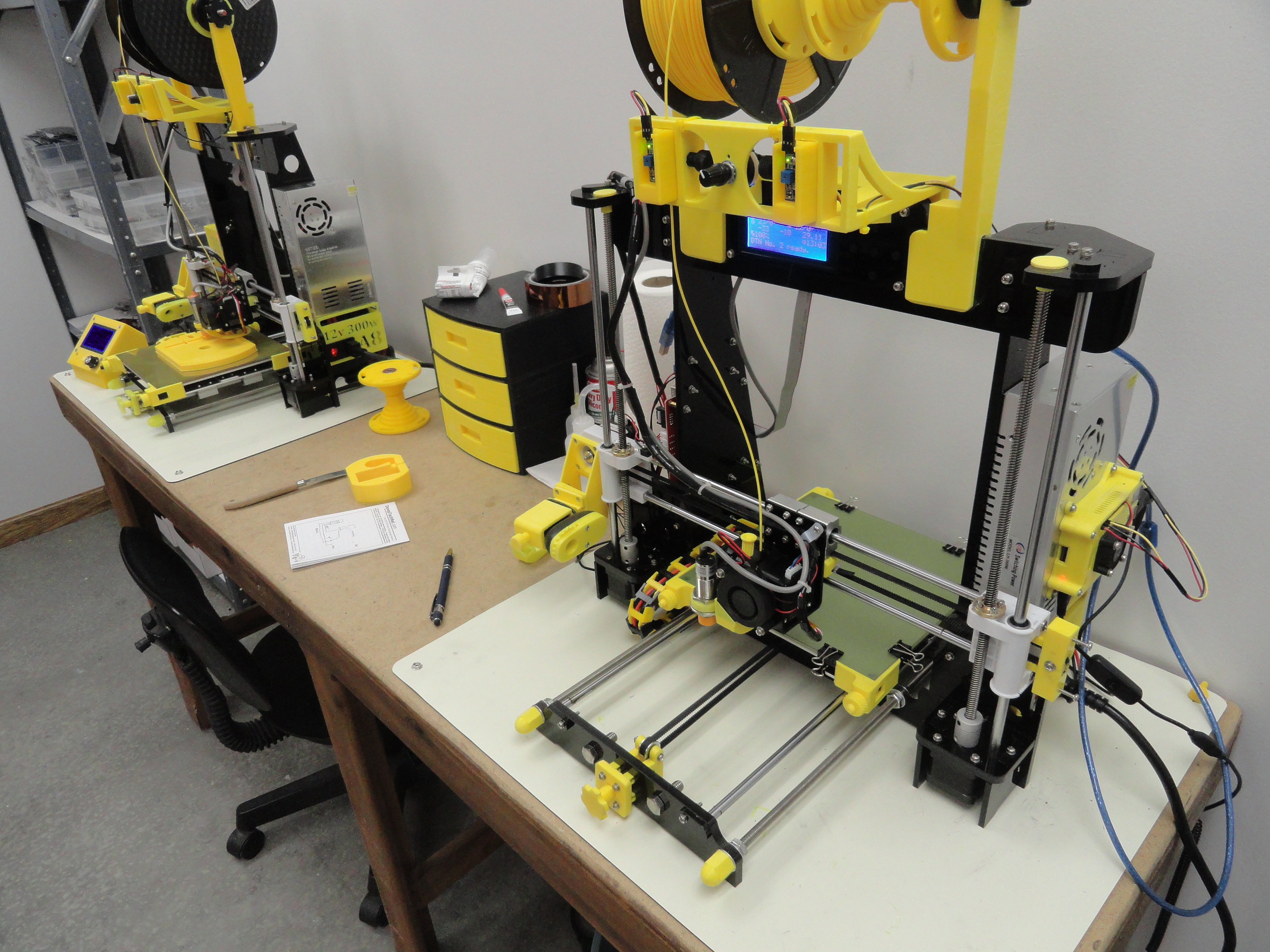
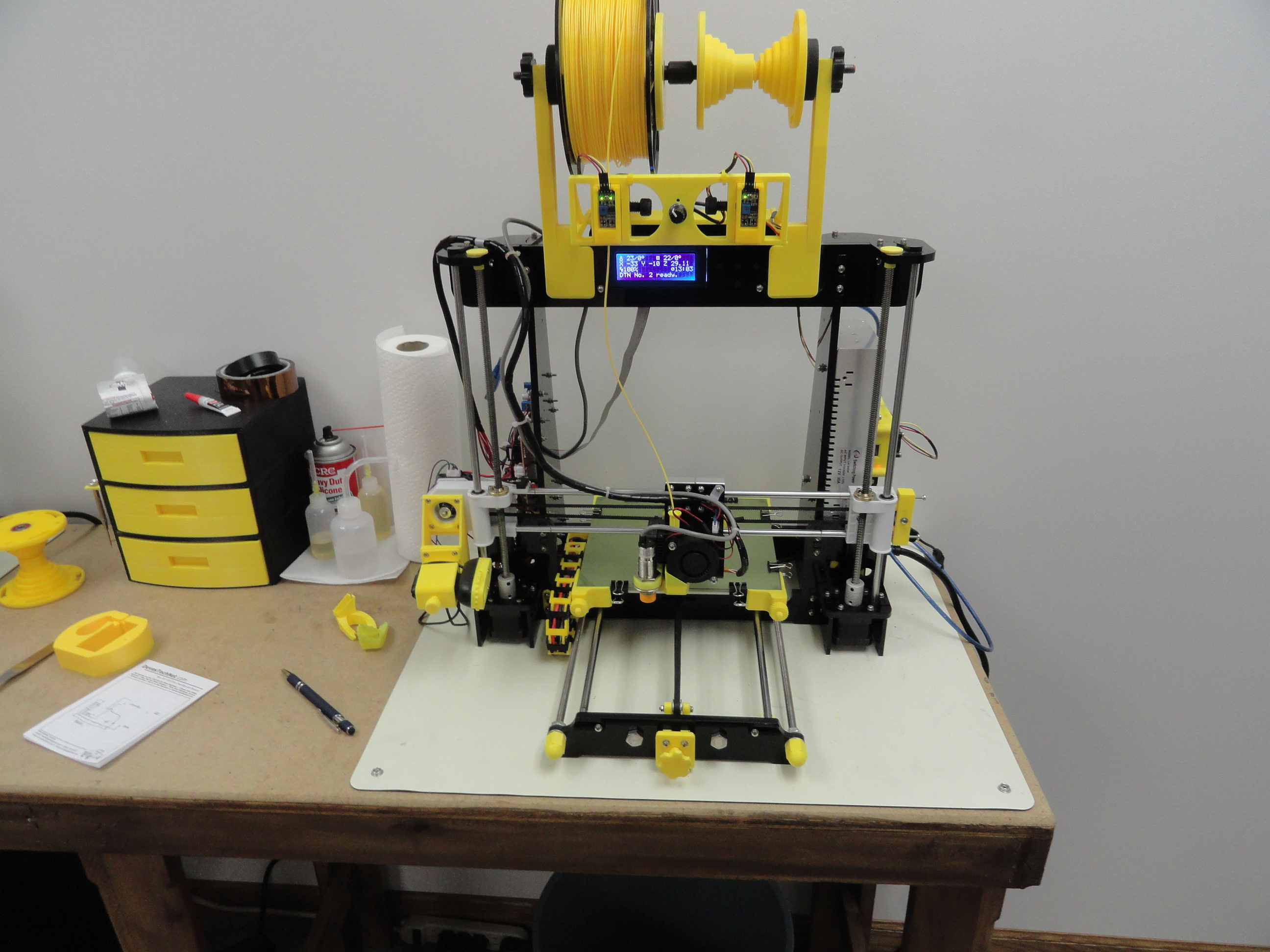
The Anet A8 3D Printer is an amazing way to introduce yourself to the world of 3D Printing. It is fully UNassembled, and really
helps educate yourself on exactly how these things work. By putting it together, you will learn things that will come in handy in
its maintenance and upkeep. And for about $150.00 US, I see no reason to hesitate. I own three of them and have for about 2 years!
They keep doing their job even though I run them mostly 24/7 all year long. These A8 Articles will explain their strengths, weaknesses,
and what to do about them.
The All-Important MOSFET
The first thing we must address is for safety reasons. Do not ignore this step! It turns out the Chinese manufacturer of the A8 did not build
enough into their current/amperage specifications. This results in burned out main boards, discolored wiring, and the possibility of
a fire. To eliminate this issue, we need to add a small circuit board that contains a Mosfet. A Mosfet is a special type of transistor
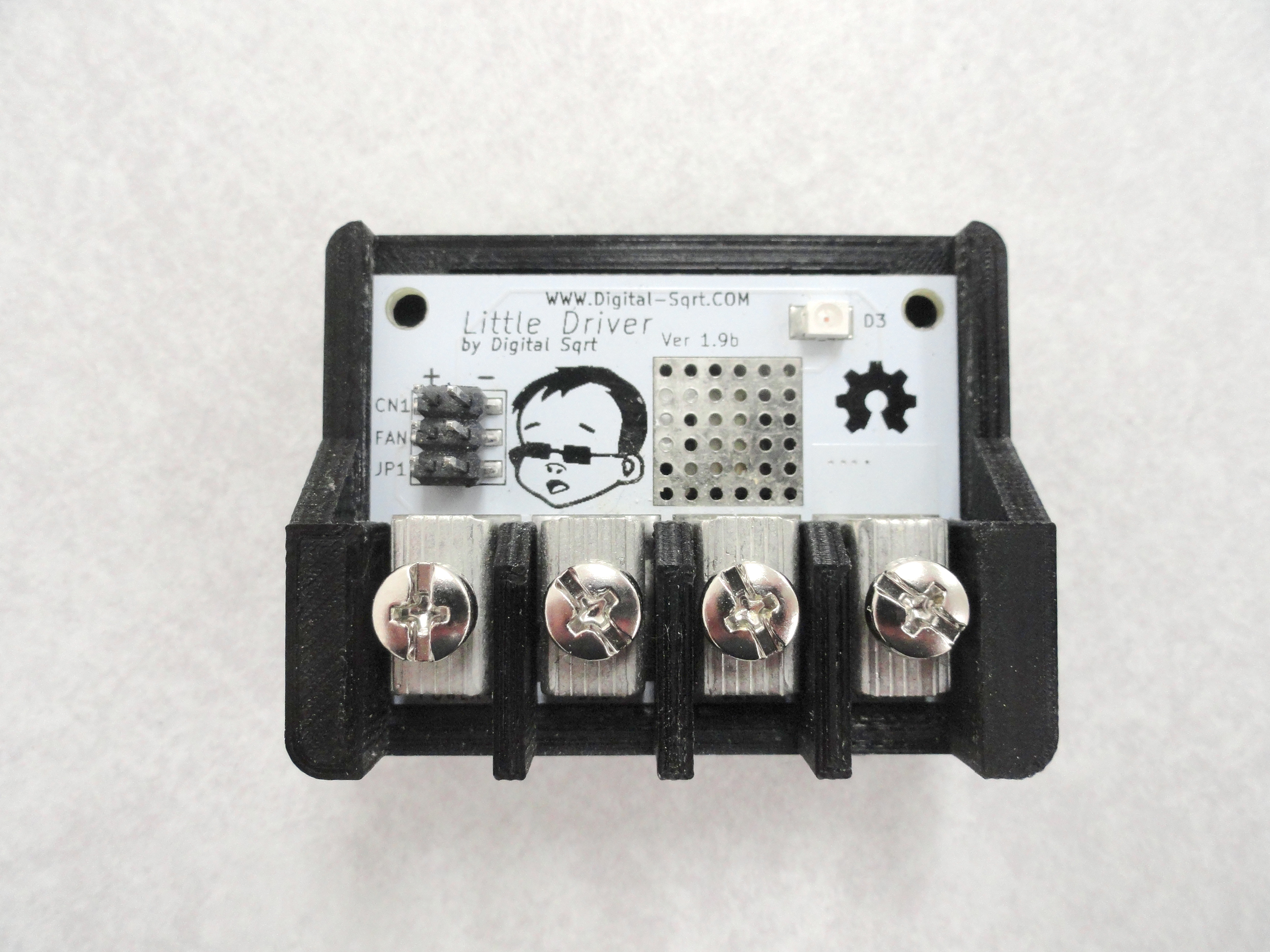
that controls the current of high current items and completely resolves this issue. Enter the "Little Driver" by Digital Sqrt. Sure you
can get a Chinese Mosfet board, but aren't we fixing this problem because the Chinese manufacturer played fast and loose with
the spec in the first place?
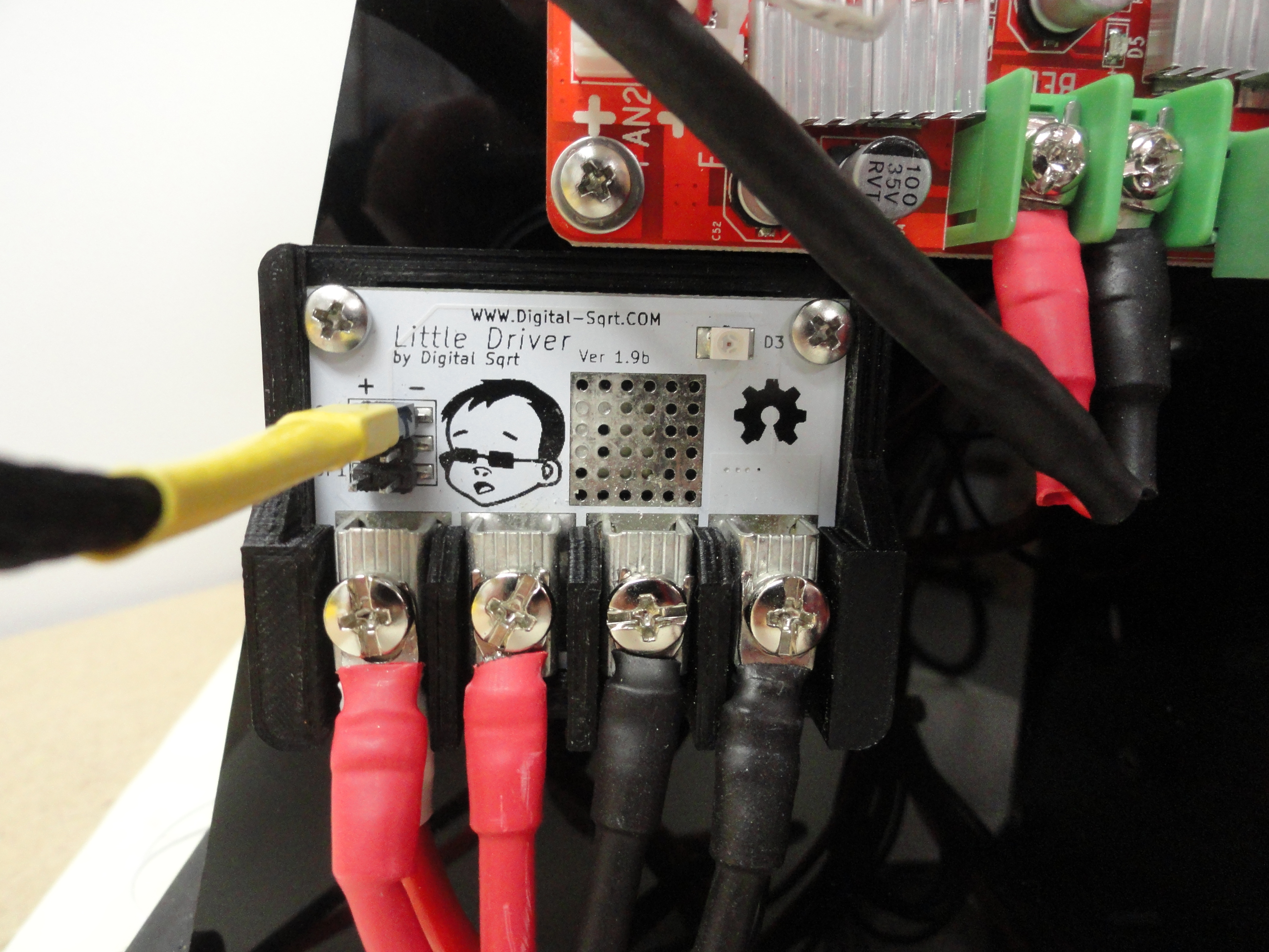
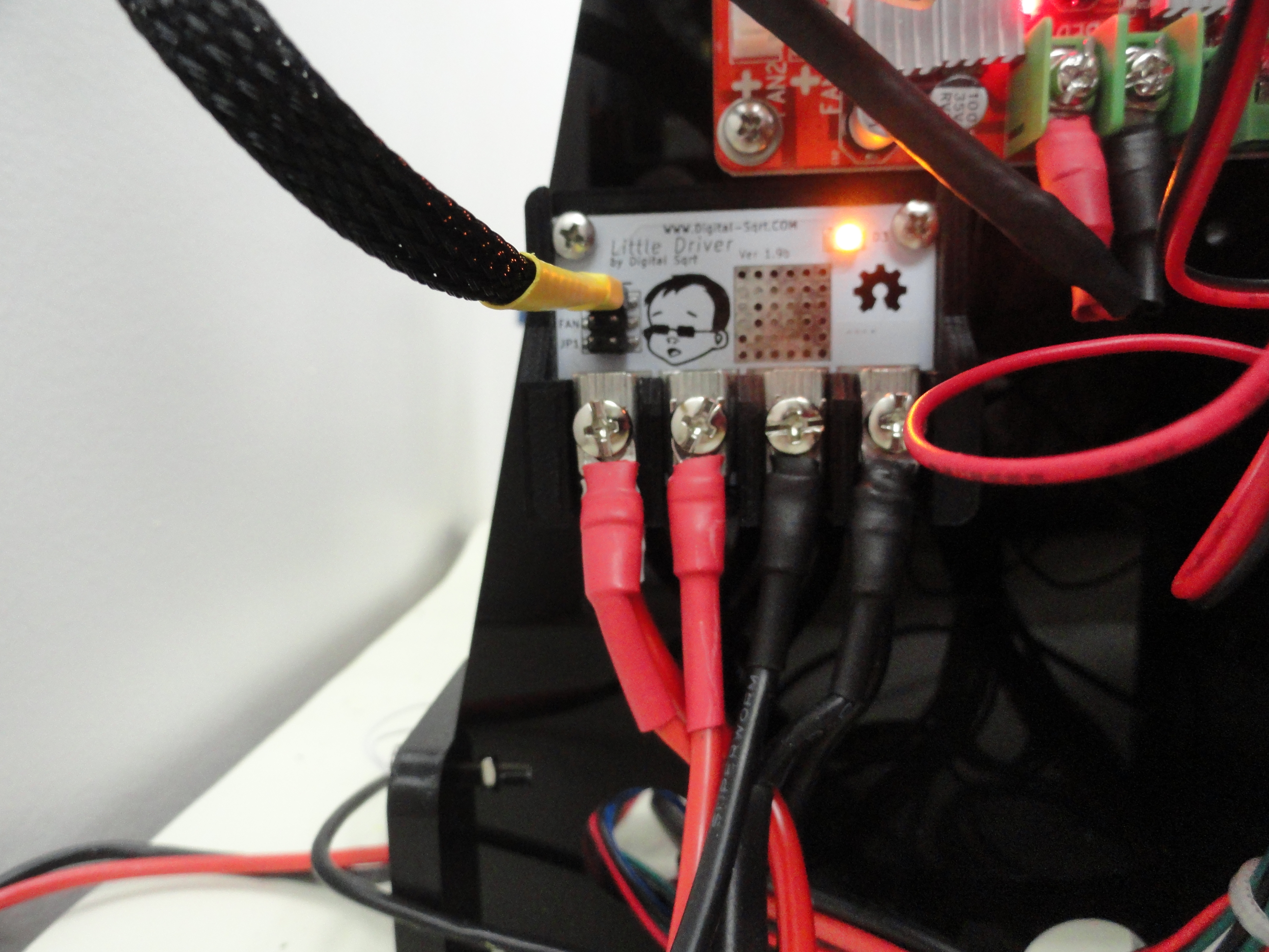
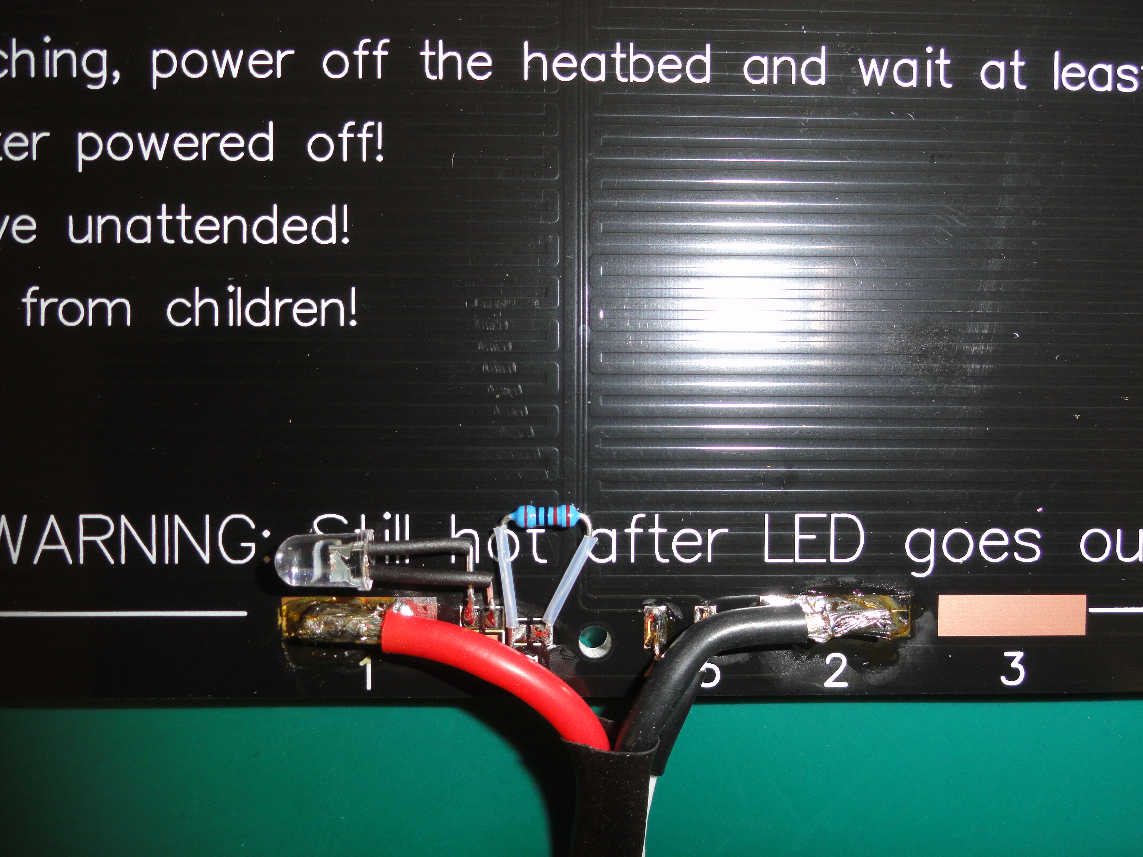
Right out of the box it was apparent that someone did their homework. The wires are clearly labeled and they even include very heavy
duty terminal ends. I suggest you use the included heat shrink so there is no chance of the wires touching each other. Connections are simple.
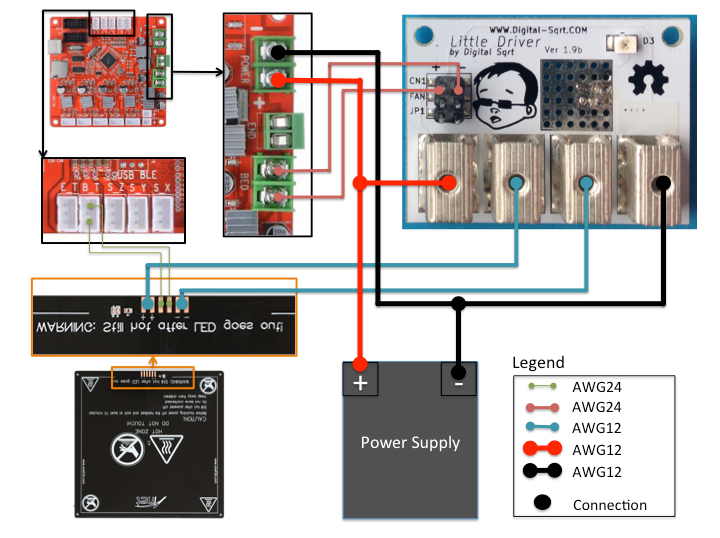
The A8 Main Board has two terminals, 12 volt positive and 12 volt negative labeled POWER in the corners of the board. Simply use the provided
thick wires and wire from the POWER terminals on the Main Board to the POWER+ and POWER- terminals on the Mosfet Board. Then, connect the
two thick wires coming off the Heat Bed to BED+ and BED- on the Mosfet Board per the Drawing.
The Heat Beds Control (thin wires) go from the two wires on the A8 Main Boards HEAT BED screw terminals as shown and then connected to the Mosfet
board at CN1. Be sure to observe Negative/Positive orientation. This is what gives the new Mosfet board the control. Digital Sqrt even made the board so the
mounting holes line up with the Chinese model so if you are replacing an old one, no re-drilling is necessary.
The board works exactly as advertised and I highly recommend this product. I like that it doesn't generate heat, does its job perfectly and I
can spend my time concerning myself with other things. We wish Digital Sqrt much success! Not convinced? Go to their website at
Digital-Sqrt.com and check out the documentation page. Very well written and very well engineered.
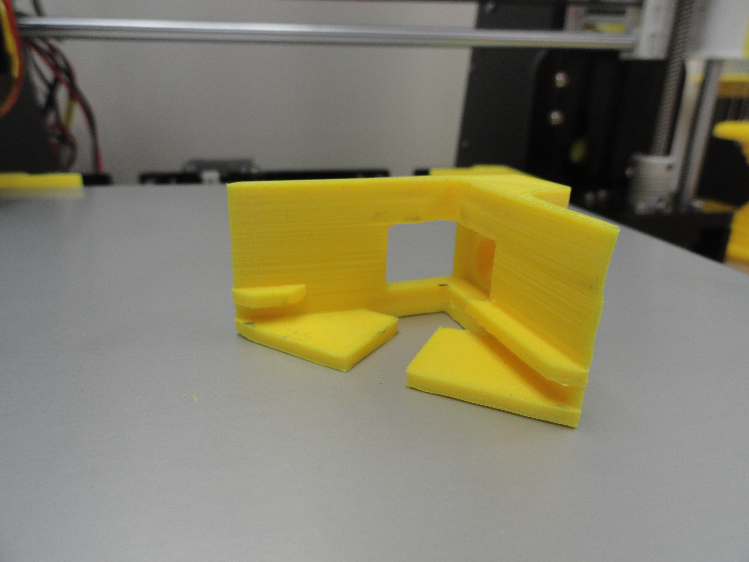
We were so impressed with this little gem, we made a very nice little enclosure for it for mounting to the side of your A8.Nifty Little Enclosure for the Little Driver
Some people use a second MOSFET board for the Extruder Heat circuit. This is not necessary at all. The current requirements for the
extruder is well within the manufacturers specification without adding another board.
The Anet A8 comes with a heated bed just like the more expensive models and masking tape is already applied to the Aluminum surface.
Masking tape is what many people use for the surface. There are many other ideas, but that is how the A8 comes from the factory. If you
Google 3D Printing Heatbed Sticking you will get a gazillion ways to make your prints better adher to the surface. You can try all of the
tricks.. Hairspray, GlueStick, Acetone/ABS, Glass, PEI, and on and on OR you can take my experience and just cut to the chase. It's completely
up to you.
We are going to fore-go all of the above with a few exceptions. We are going to get perfect results each and every time afterwards. We will not
be looking back! This will cost you a little bit, but you saved so much on the Printer, there is no excuse to cheap out on certain things, this
being one of them. First get yourself a piece of glass. Not just any glass! Regular window glass cut to size is a very bad and dangerous idea.
The reason for this is because every now and then, the Heat beds proximity sensor looses its mind and the nozzle trys to destroy your bed. This
can happen due to a power glitch and it happens very rarely. Nonetheless, it will break that kind of glass and you will have glass all over the
place. Do not cheap out on the glass!
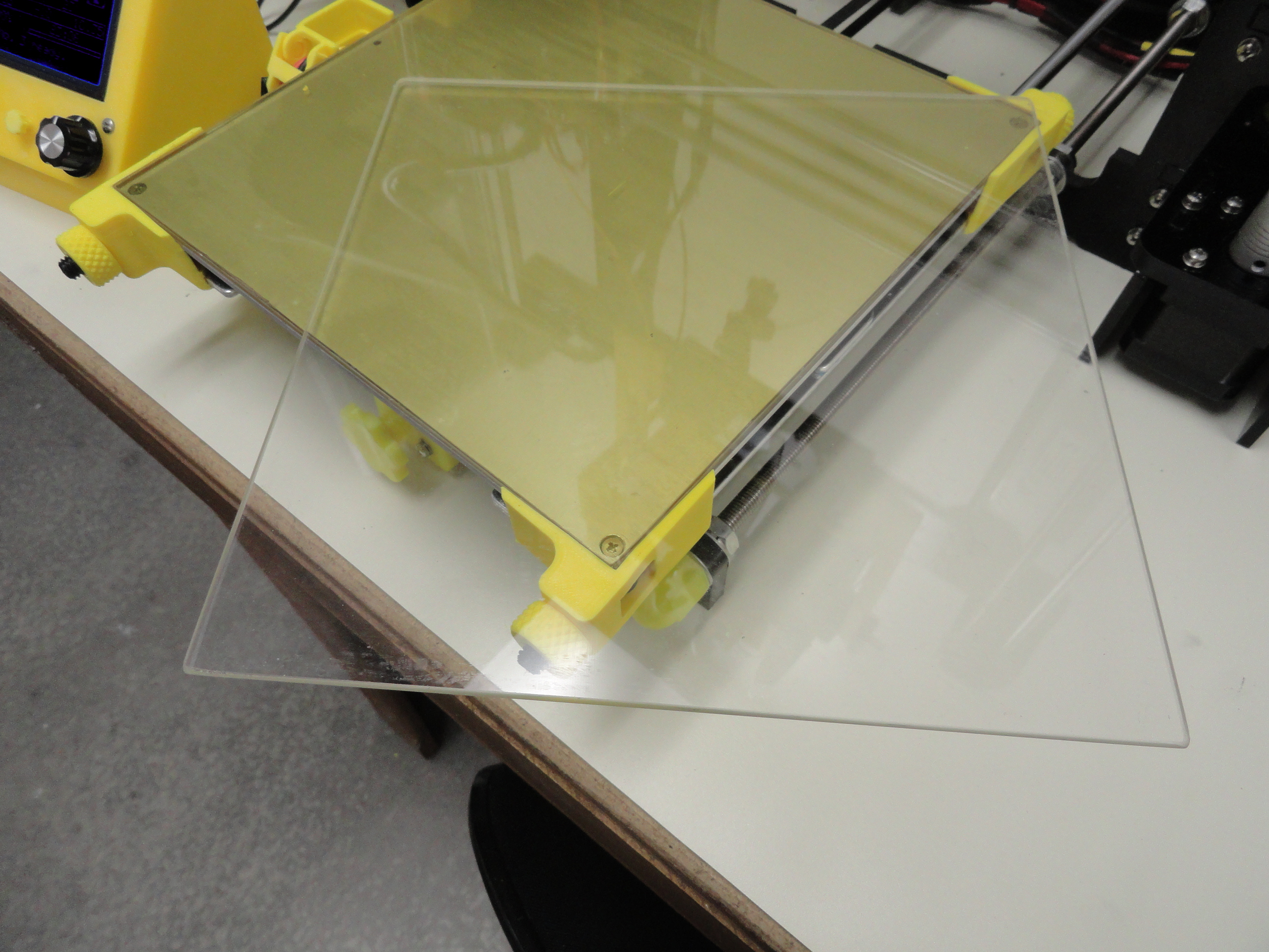
The Glass
What you want to get is a 220mm x 220mm x 3mm piece of Tempered Glass. The ones I get off Ebay are nicely sanded on all sharp surfaces and work
perfectly. They call the stuff Boroscillic Glass. To make a long story short, since they use Boron Trioxide they have a very low tendency towards
thermal expansion and they are more resistant to Thermal Shock. The cost of one piece of this is about $23. Just do an Ebay search for Boroscillic
Glass 220x220. This is only the first step and sets us up with a perfectly flat surface for the next step.
The PEI
Now we need to add the sticking surface. Enter Polyetherimide (PEI). This is a very special thermoplastic that provides high strength at elevated
temperatures and outstanding dimensional stability meaning the Print will stay put without using anything else. You also want a thick piece of PEI
and not some .3mm thin stuff that ends up being ruined very quickly through normal use. Get in the very least a .8mm thick piece that is 220mm
x 220mm. Do a search on Ebay or Amazon for PEI Ultem 1000 220x220 .8mm. Expect to pay roughly $20 a sheet. But do not stop there! Make sure it comes
with a sheet of 3M 468MP Adhesive.
Applying this PEI to the Glass is NOT fun nor easy. I warn you up front it is hard so be really on your game when you attempt this. The problem is the
adhesive really works! You have to start it perfectly and then with a credit card as a spreader, slowly, VERY slowly and carefully press it down to the
glass first. Then remove the protective film on the PEI sheet and then press the PEI down. Really push with that Spreader and get it down good without
air bubbles. Its not easy. Did I say that enough? (Don't answer until after you have tried it). Alternately, you can use book binders to hold the PEI
down to the glass. The good news is, PEI lasts a VERY long time. I change my PEI out about once a year. I do that because of gouges I made when lifting
the prints, or the head getting a tad low and scraping on the PEI sheet. You can actually sand this PEI smooth again with 600 grit paper if you wish.
The only problem with using book binders is, every once in a while you will decide to print something that is very big and nozzle may hit the binder
and snag on it and cause a minor catastrophy. As time goes by, you will get better at getting that Adhesive to lay down correctly. There is good news...
The good news is, PEI is TOUGH. I always test the PEI that comes in prior to installing it by swiping one side with Lacquer Thinner, which is what I
routinely use for cleaning the surface anyway. If it clouds up and gets nasty and discolored, someone tried to sell you Lexan or some other plastic.
Get your money back! (This happened to me!) I put the book binders on so you can see what they look like.
The Hardware
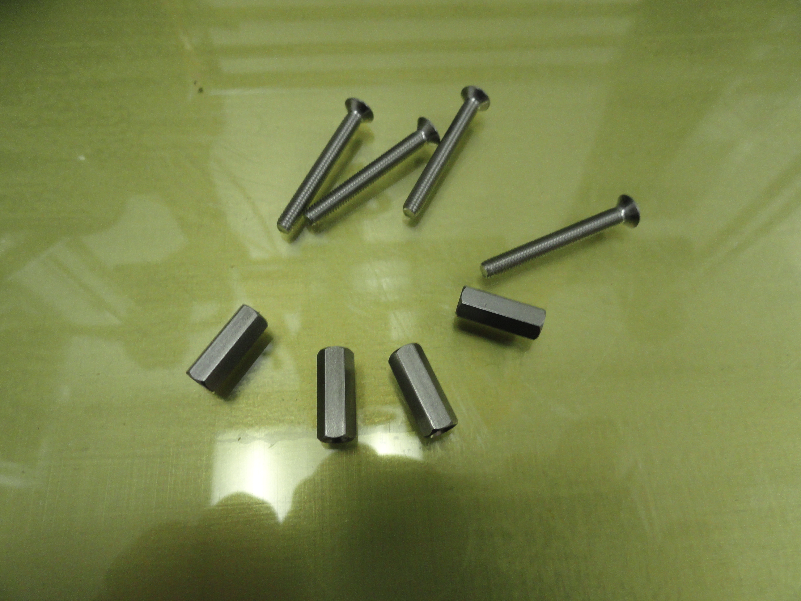
Next we need to scrounge up some non-standard hardware. We are going to do something unusual but very effective. We are going to remove your ability
to level your bed! Trust me. Get yourself 4 Hex Female Standoff Insulators (metal) that are 12mm or 1/2" with 3mm threads. Also, while you are at it, get at
least 4 22mm or 1 inch Flathead Stainless Steel Screws. I get this stuff at McMaster-Carr. While you are waiting for those to come in...
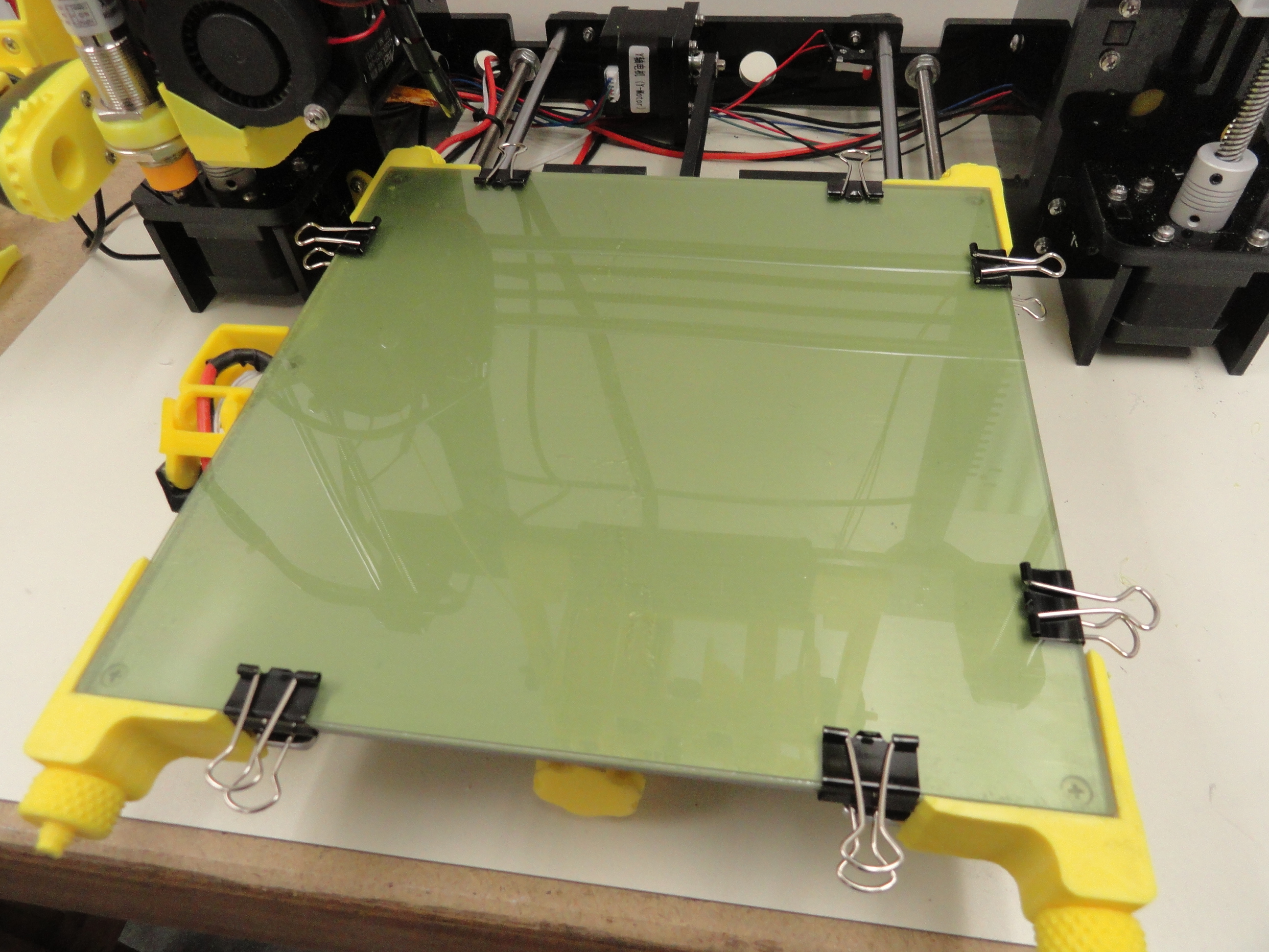
So you have your PEI adhered to the Glass. Now you have some printing to do to finish this wonderful setup. Lay the glass on the clean aluminum surface
minus the masking tape. Use two book binders on all 4 edges to ensure the glass does not move for now. With a little 3D Printing, we are going to fix
this problem once and for all. Its always good in this business to have those medium book binders just in case.
I was very skeptical that bed leveling springs were bad idea until I put this system on all of my ANET A8 Printers and without the springs and ability to
level the bed, I found I was able to get a much more accurate first layer. It has to do with how the bed is oriented in relation to the Axis' and
the way the Z screws are ganged together, not adjustable separately. You are actually fighting against yourself by changing the corner positions using the
spring method. Crank them down to the max and watch how much better the first layer and all subsequent layers turn out!
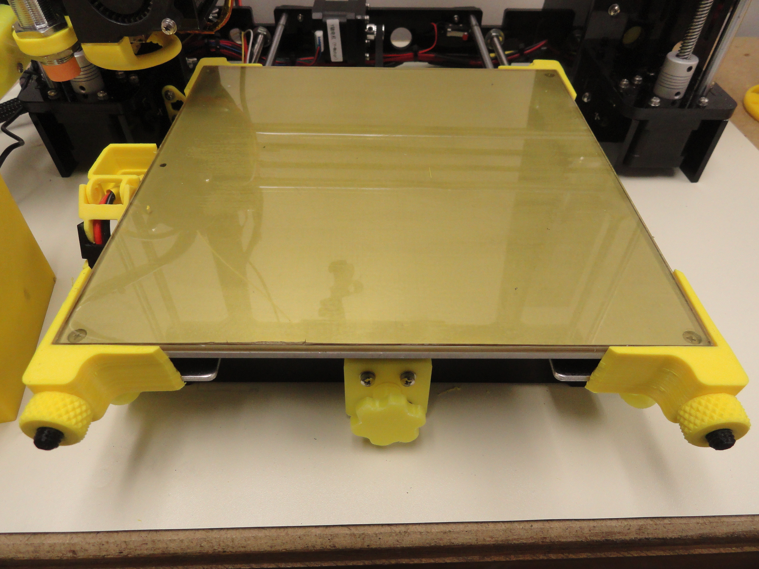
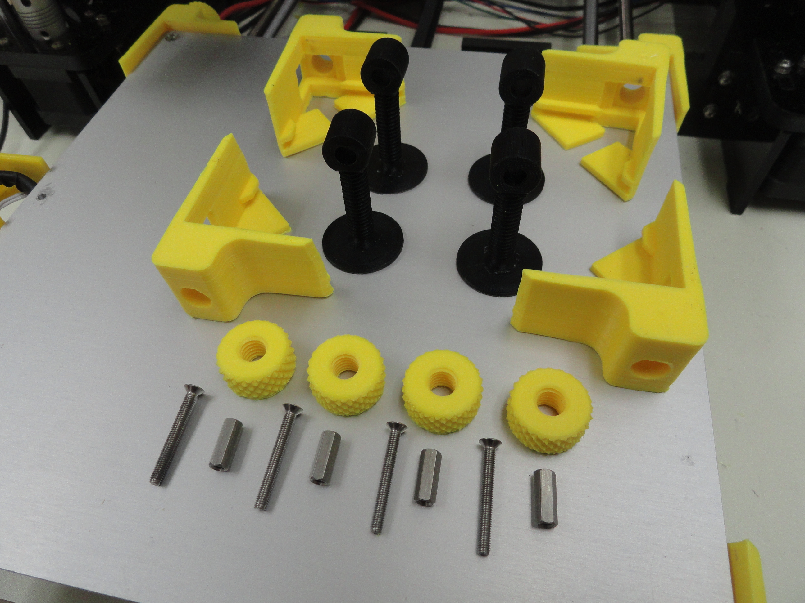
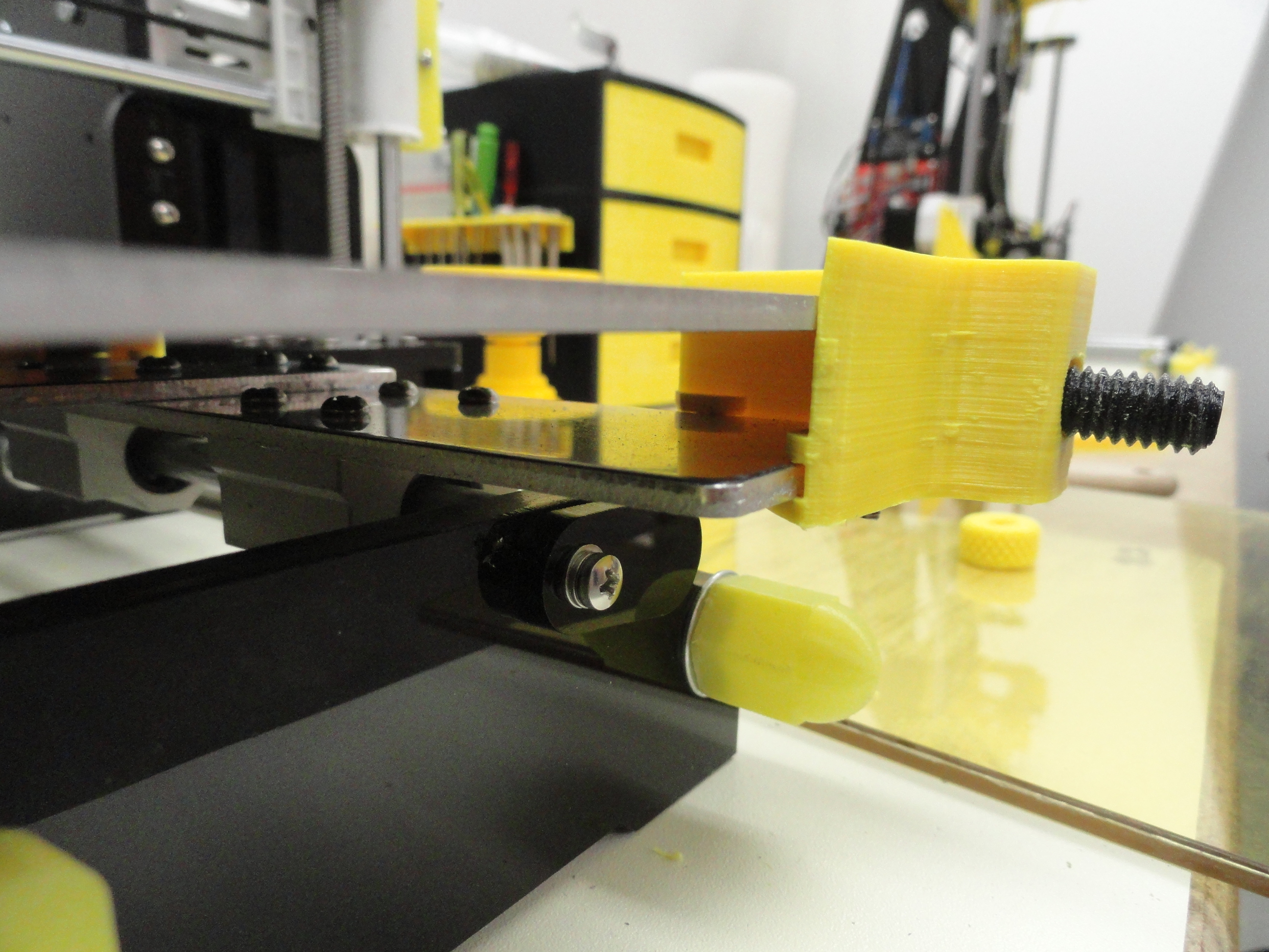
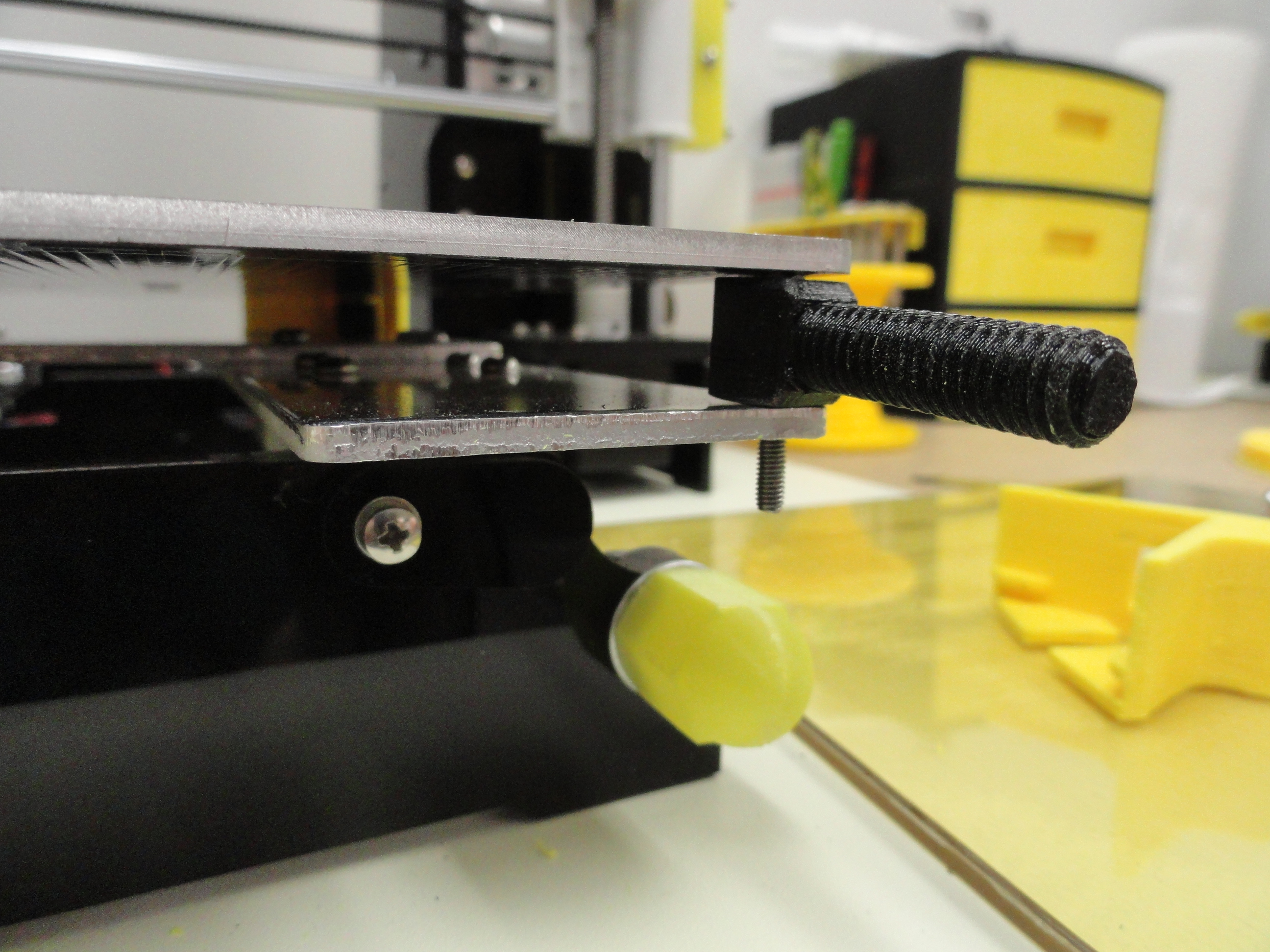
The Glass Bed Hold-down System
I made this Glass Bed Holddown System using Fusion 360 which is currently free to hobbyists. Below is the STL files for printing direct as well as the
main Fusion 360 files. This way you have everything you need to customize this system. No more book binders after this! This system consists of: 2 Left Corners 2 Right Corners 4 Bolts 4 Nuts Fusion 360 Zip
A good idea when printing bolts is to print them standing up. This means putting a nice base on them and a thinner shaft near that base. Simply
snap them off the base and they are 100% ready for use! I almost always have support turned on with an 86 degree minimum support overhang angle
so it does not put support on things I do not want. With PEI you will be happy with a BRIM of 5 rounds or none at all. I use the latest Cura for
all of my Slicing and Printing.
Print 4 of the nuts and bolts and 2 of each left and right clamp.
STL Files ready for 3D Printing
Fusion 360 Files ready for making changes.
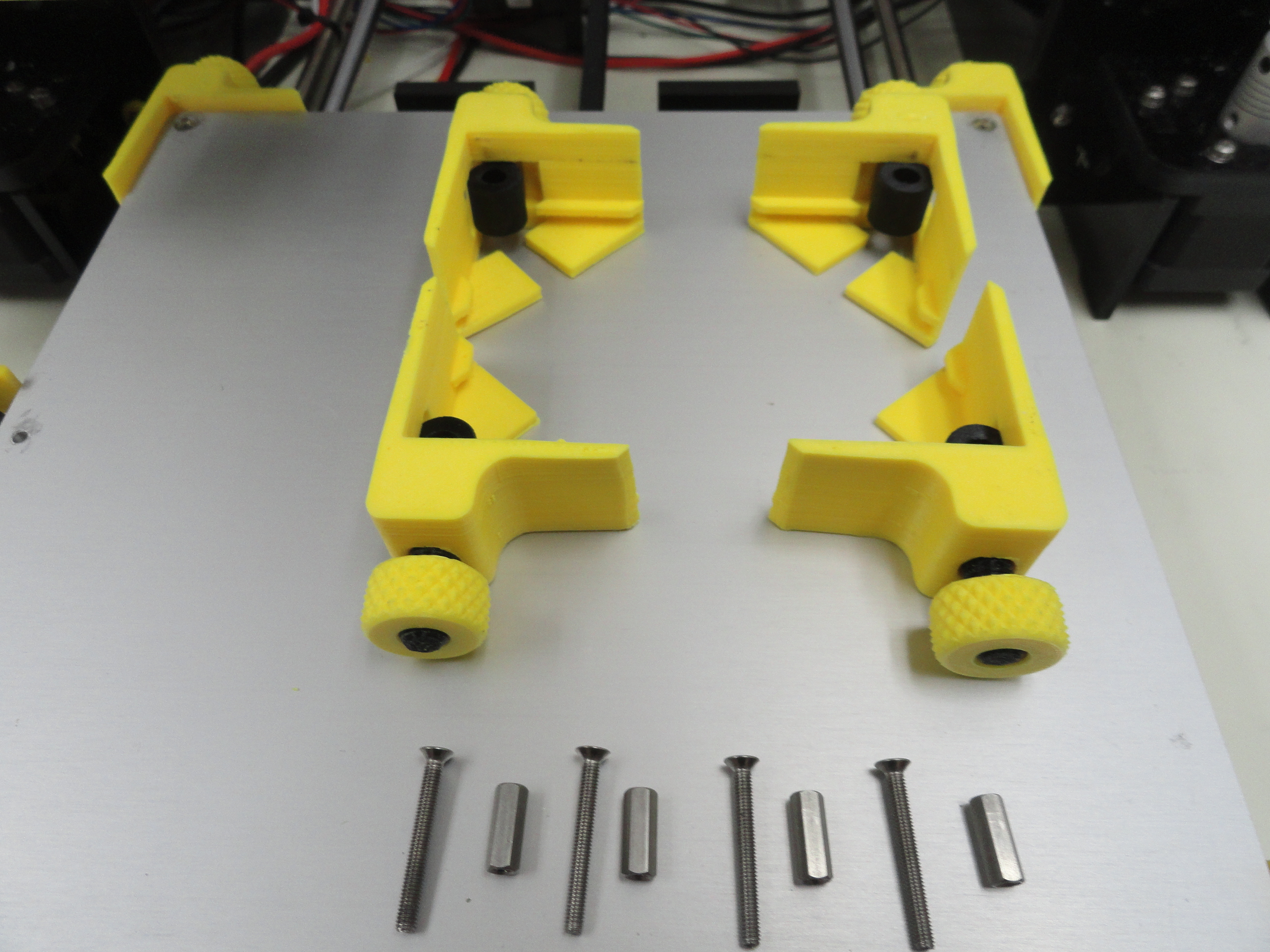
Remove the Heated Bed from the table by removing the 4 screws holding it down. Remove the springs and store them for posterity. Put one standoff inside
the hole in the plastic bolt, then run the 22mm by 3mm flat head screw down through the bed and bracket assembly. Be sure the plastic screws are pointing
front to back. Do this on all 4 corners.
Next we slide the corners into the plastic bolts observing front to back orientation. Make sure they slide into the bottom bracketry as they are designed
to do. Look that over before starting them. You will see the track the corner is supposed to take. Slide them in nicely and install the back ones first,
then put the round plastic nut on them and tighten them down. Do not overtighten, snug is fine. Do the same for the front except install the glass/PEI
combo, THEN tighten the front corners down. From now on, to remove the glass, just loosen the two front ones.
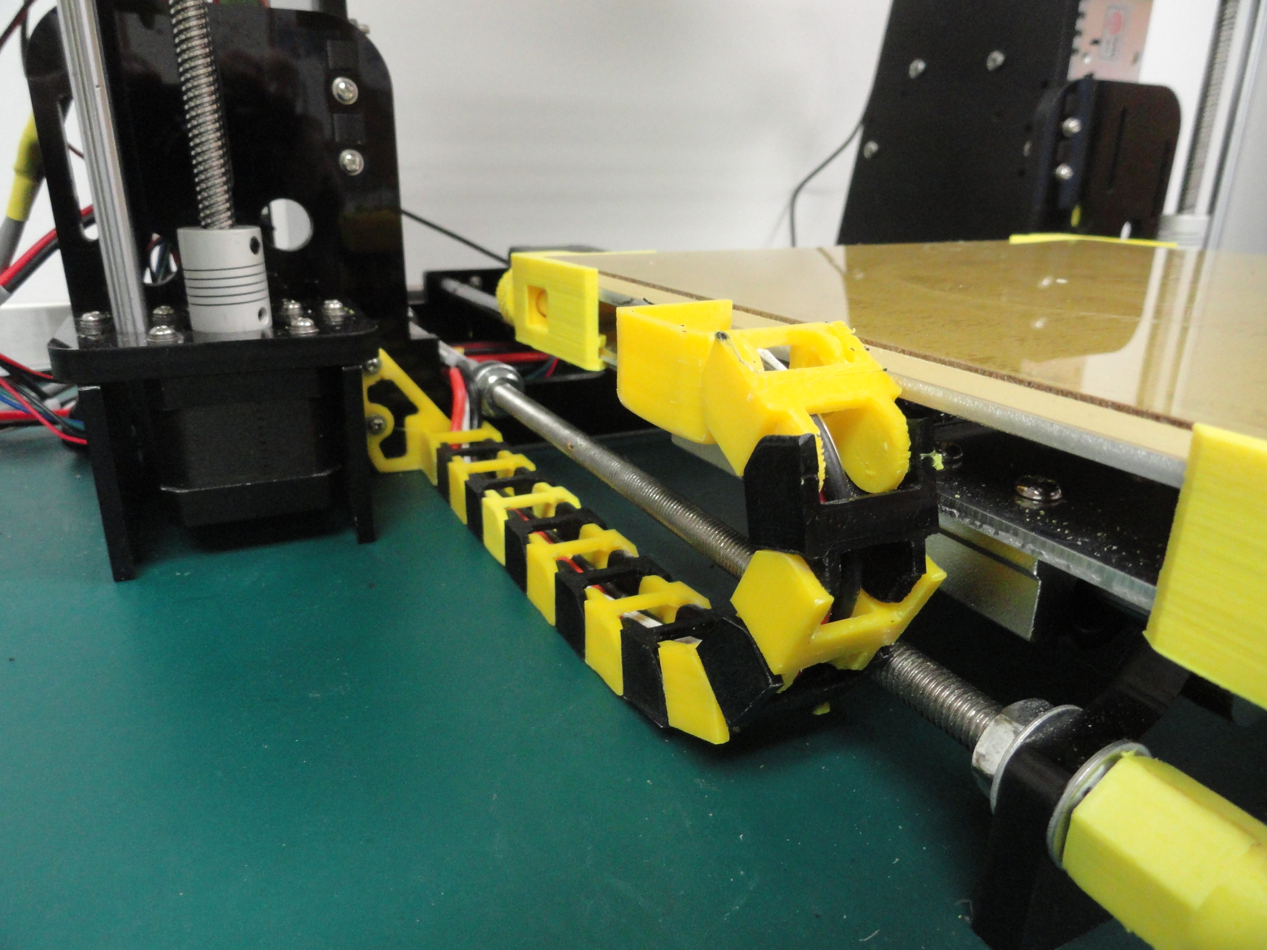
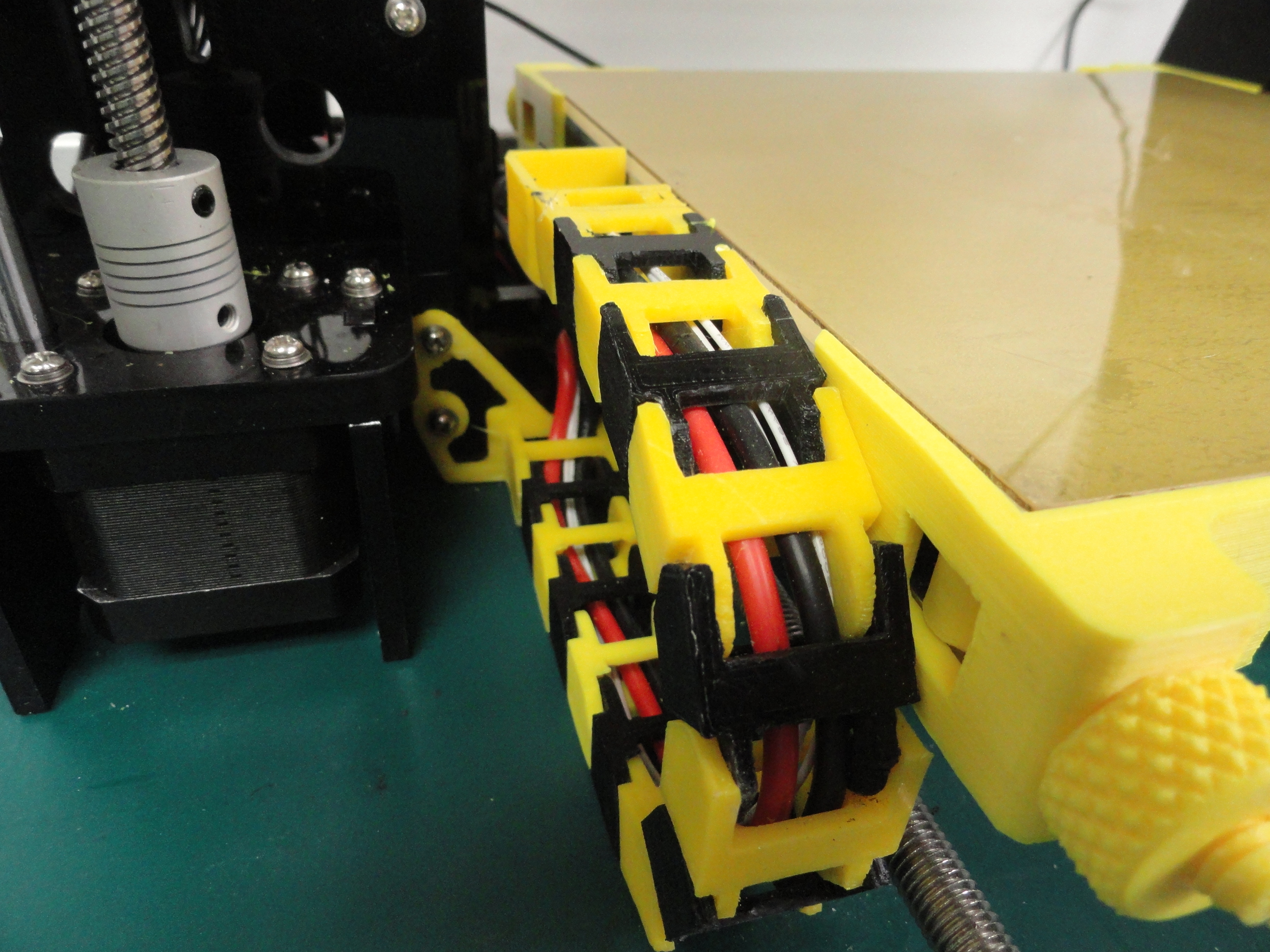
A side benefit to this system is, it is CHAIN friendly. With or without a chain, these corners really do the job. See the photos if you do not know
what a chain is. It is merely a way to protect the wiring system from the abuse of the table going back and forth repeatedly. I highly recommend you
install a chain. It takes patience and a little work, but worth it. Soldering is required.
The Heated Bed Chain Modification
Once you have printed the 16 chain pieces that you snap together and have the two ends printed, you will be rotating the bed 90 degrees
so the connector is on your left facing the printer as shown. Be very gentle when removing the connector from the heat bed. They made these beds really
cheap and the printed runs can lift off and ruin your day. Don't force anything. Heat it sufficiently to remove it properly, then place a pad of solder on
the runs where your new wire will go. If you are a fanatic like me, use replacement SILICON wire. It is very flexible and very unlikely to break ever.
Do a search for 14 AWG Soft High Strand Flexible Silicone Wire. You can get 20 feet for about $8. It is things like this that make this printer better
than the more expensive ones over time.
The Chain Links
This was not worth my time making in Fusion 360 when Thingiverse has decent ones already. Go here and download the files. Print them at 100% Infill. There
are certain things we do not cheap out on by making them less solid. You need 16 Chain Links. Print the Heatbed and Frame ends and everything nicely snaps
together.
Cura Profile Settings
Cura Page One
Cura Page Two
Cura Page Three
Cura Page Four
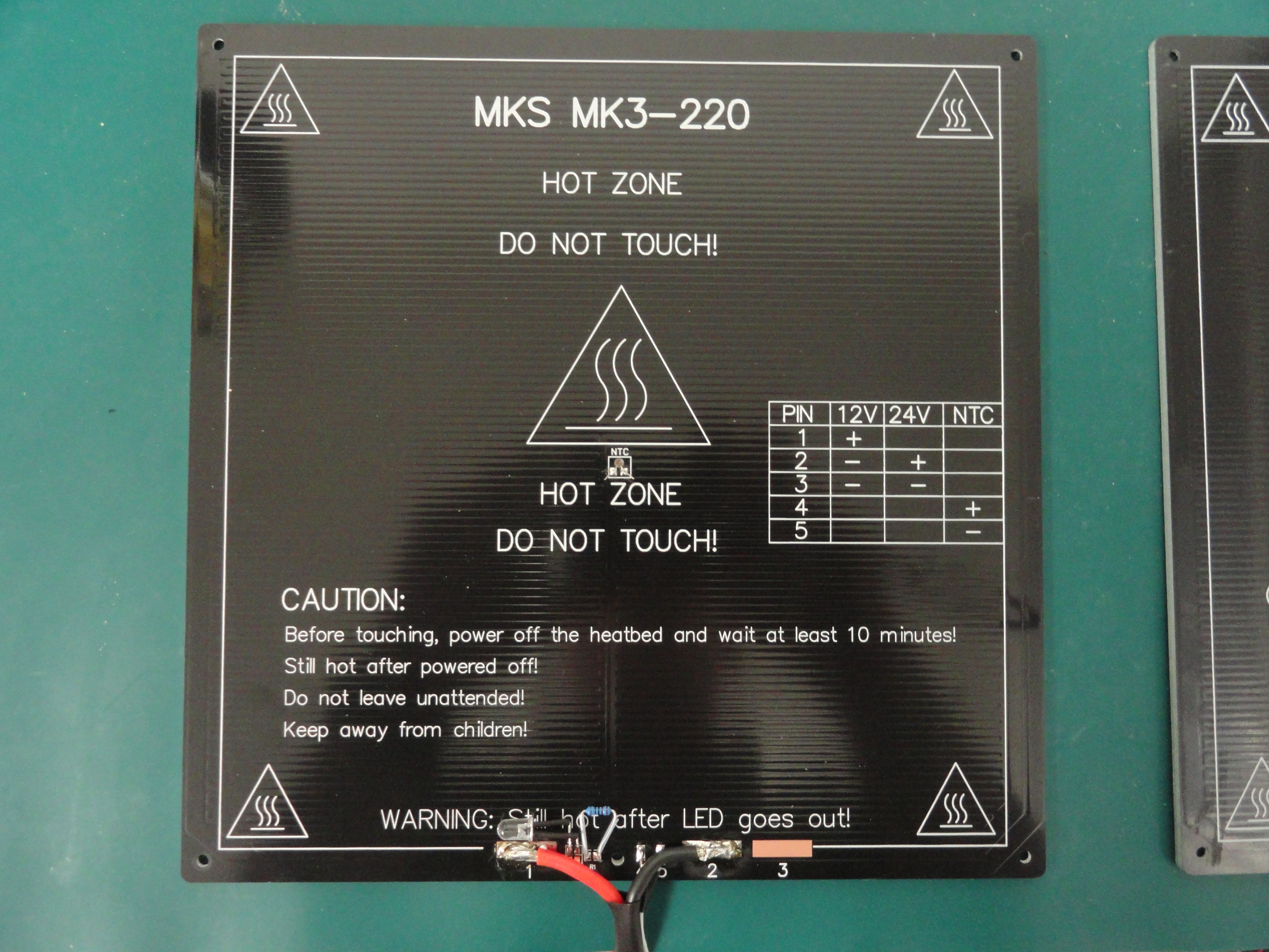
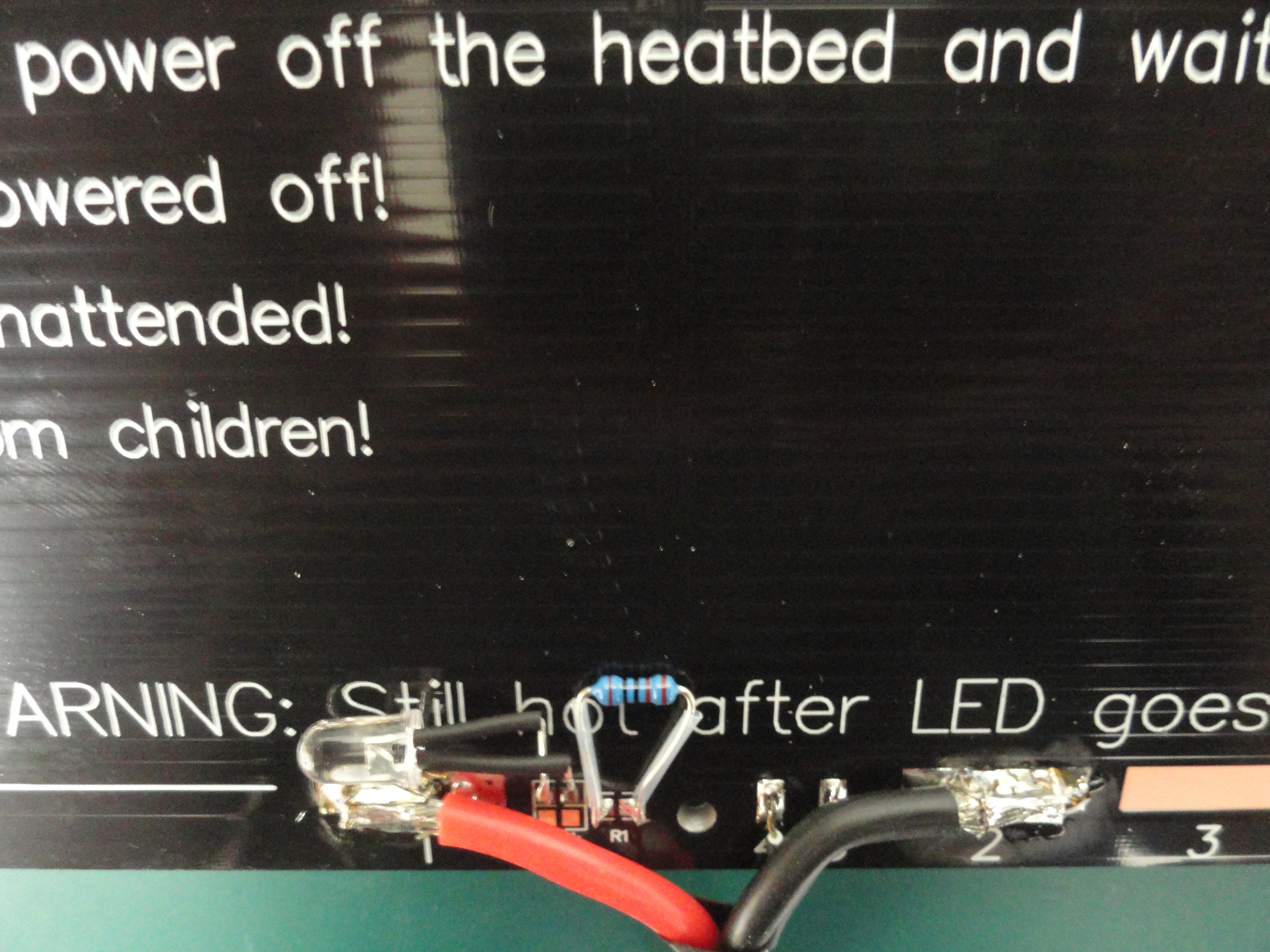
The Heat Bed
The Heat Bed that comes with the A8 will do nicely, but when it comes to replacing it, there is a slightly better alternative. I find it works well and spreads the heat
out well. The problem is there is a lot of soldering to do since none of the LEDs, Resistors or wires are connected. In fact, it doesn't even come with those parts! When I
complained about this, the company sent me the VERY VERY TINY (did I mention small?) resistors and LEDs that I can barely see, let alone solder! Here was my workaround:
One of the problems with the stock A8 is its heat bed connector. It will not take long for it to die on you. Usually it's a burned ground connection.
They did not use beefy enough connectors. This is a good opportunity to change that. Do not be afraid of soldering! Just watch a few tutorials on the
internet and off you go!
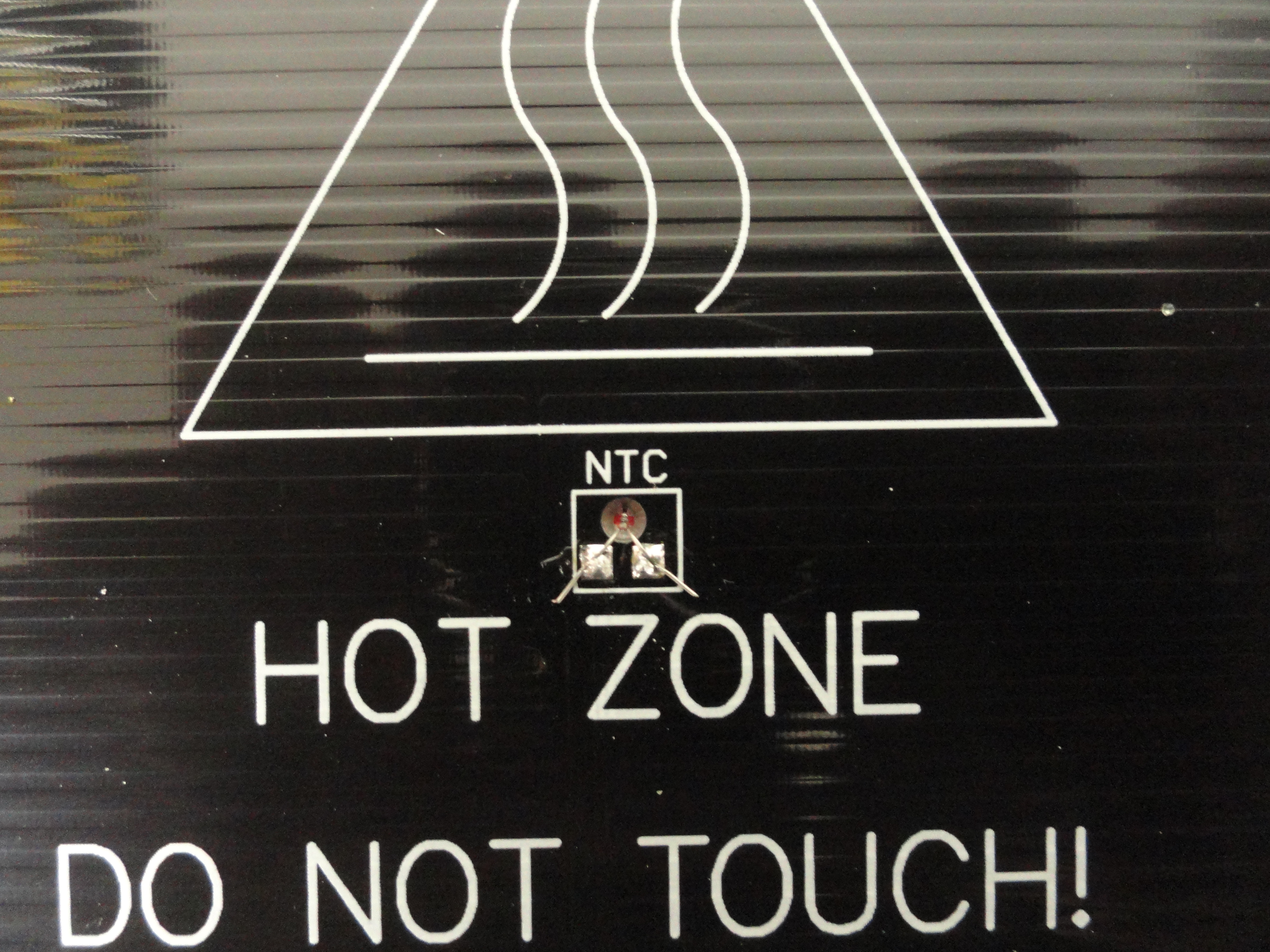
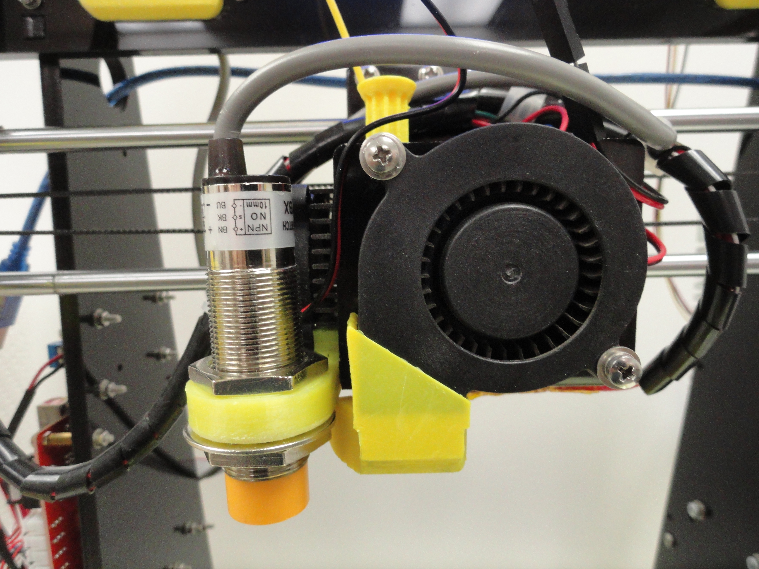
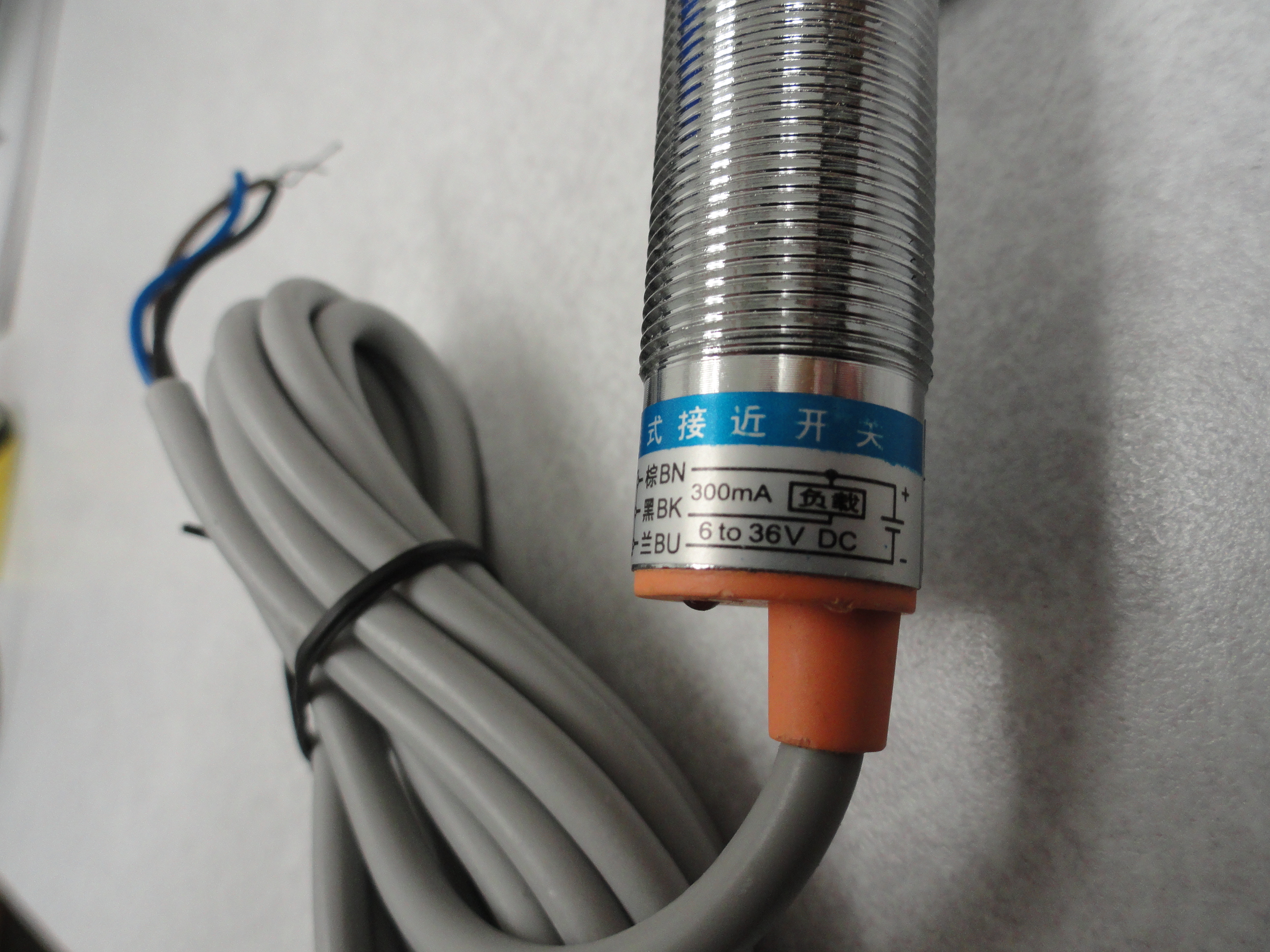
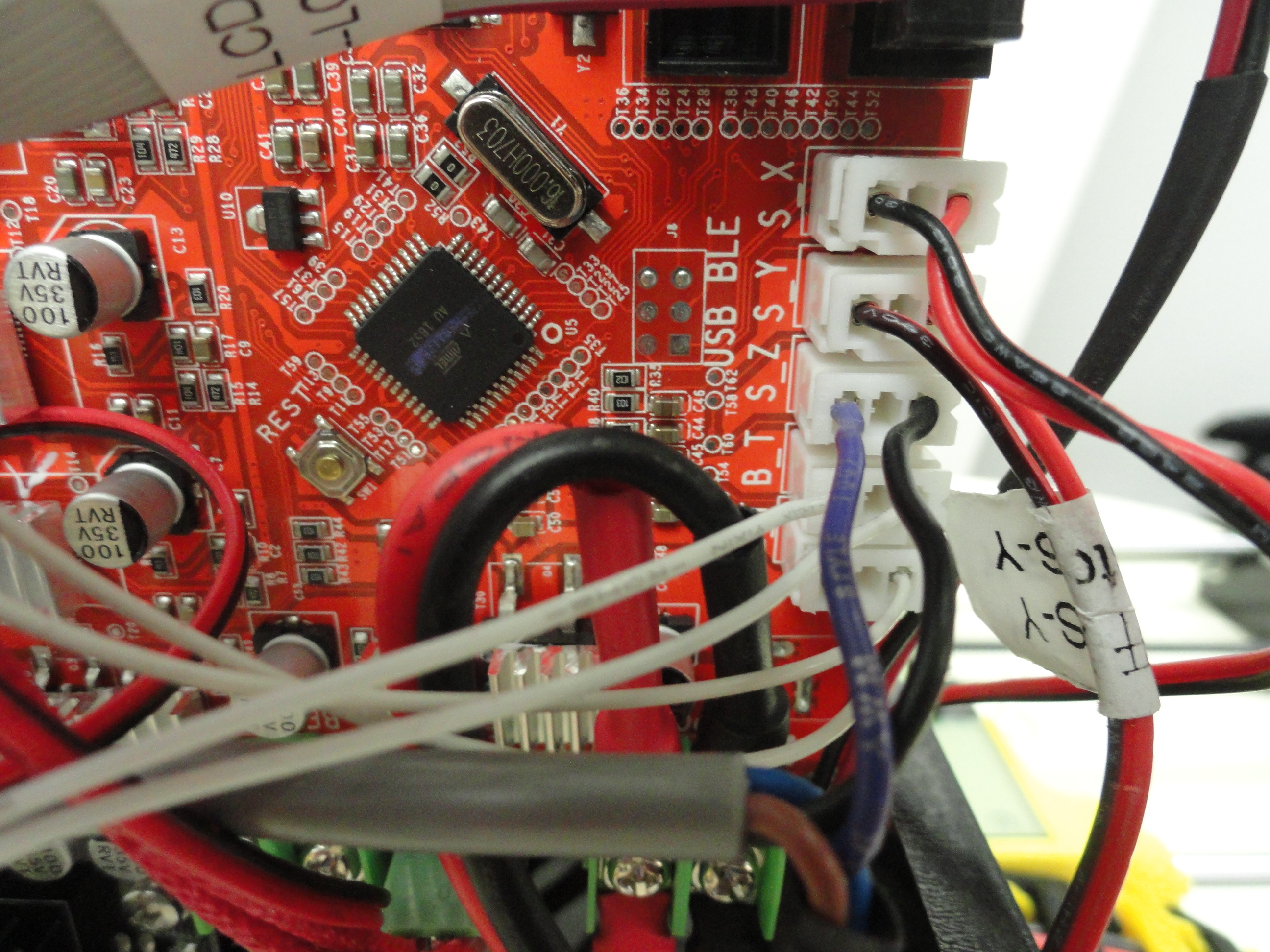
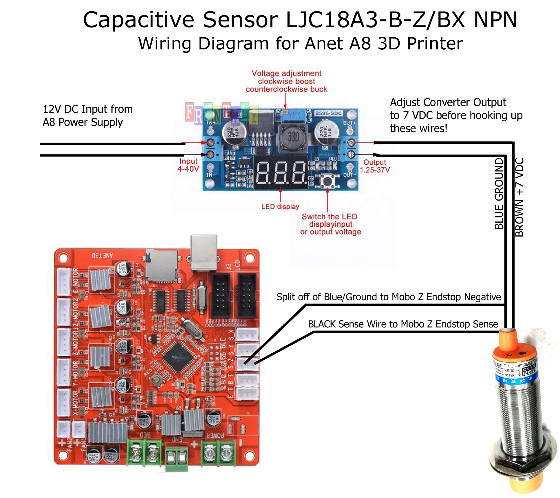
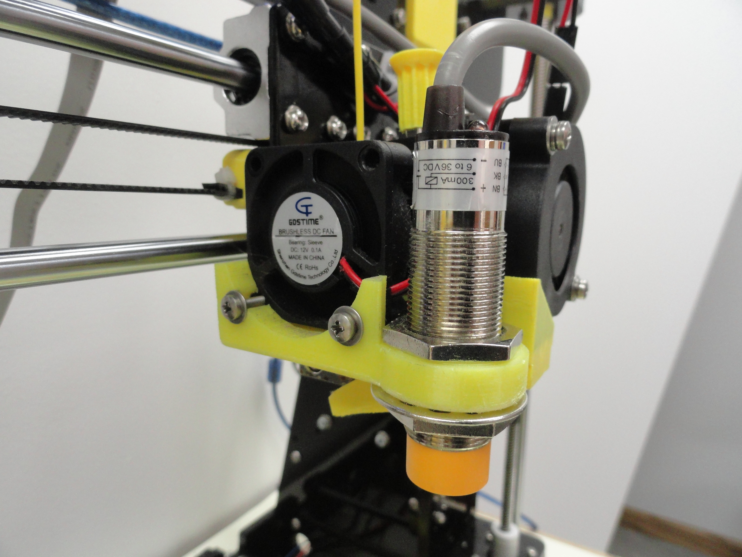
Bed Leveling Sensors, the Real Story!
Next we will discuss Bed Leveling Sensors and exactly how to connect them. First off, I will assume you followed my advice and have a 3mm glass with
.8mm PEI sheet on top. This fact alone eliminates a great deal of the conversation. The sensor that works best for that combination hands down is
the Capacitive Sensor. Capacitive Sensors can see through PEI and Glass and reflect off of the Aluminum substrate. This is the most accurate sensor
available for glass/PEI. I have never tested just how accurate because it gets the bed into perfect position about 97% of the time. Hard to improve on
that. The other 3% is very likely anomalies in motherboard sensing capability. I never start a print without watching the start of it and I have been
very pleased with the LJC18A3-B-Z/BX NPN Capacitive Proximity Switch. I use it on all of my A8's. Remember, the Inductive sensors do not see through glass
and are wonky on PEI and sensors that actually touch the bed are a bad idea since they are mechanical and can wear out quickly. I am very grateful for
how well these work.
Marlin for 3D Printing
The reason I am putting this here as well as in other places on the website is because the software you use will effect your bed leveling capability. The
only real choice for making this Printer do amazing things without a lot of fiddling around is Marlin. It looks daunting when you start off, so
here are a couple of tips to help you keep things in order. Marlin is free and we are so appreciative of the Marlin Team. There are several methods of
bed leveling that are available with Marlin, but the one that I use is Auto Bed Leveling Linear. I am not an expert at this, but I know it works. I
encourage anyone who understands this clearly to contact me so I can write about this better. So be forewarned, this works perfectly for me, so I feel
okay with sharing.
I will not go into tremendous detail on how to set this up because there are more expert people out there you can listen to, however here is my
configuration.h file for Marlin 1.8.3. If you have a Ramps 1.4 or other than the A8 Stock board, change accordingly. Be sure you save your current
configuration.h file before you do this under another filename so if you have adverse problems, you can go back and start over.
/**
* Marlin 3D Printer Firmware
* Copyright (C) 2016 MarlinFirmware [https://github.com/MarlinFirmware/Marlin]
*
* Based on Sprinter and grbl.
* Copyright (C) 2011 Camiel Gubbels / Erik van der Zalm
*
* This program is free software: you can redistribute it and/or modify
* it under the terms of the GNU General Public License as published by
* the Free Software Foundation, either version 3 of the License, or
* (at your option) any later version.
*
* This program is distributed in the hope that it will be useful,
* but WITHOUT ANY WARRANTY; without even the implied warranty of
* MERCHANTABILITY or FITNESS FOR A PARTICULAR PURPOSE. See the
* GNU General Public License for more details.
*
* You should have received a copy of the GNU General Public License
* along with this program. If not, see
#define ENABLE_LEVELING_FADE_HEIGHT
// For Cartesian machines, instead of dividing moves on mesh boundaries,
// split up moves into short segments like a Delta. This follows the
// contours of the bed more closely than edge-to-edge straight moves.
#define SEGMENT_LEVELED_MOVES
#define LEVELED_SEGMENT_LENGTH 5.0 // (mm) Length of all segments (except the last one)
/**
* Enable the G26 Mesh Validation Pattern tool.
*/
#define G26_MESH_VALIDATION // Enable G26 mesh validation
#if ENABLED(G26_MESH_VALIDATION)
#define MESH_TEST_NOZZLE_SIZE 0.4 // (mm) Diameter of primary nozzle.
#define MESH_TEST_LAYER_HEIGHT 0.2 // (mm) Default layer height for the G26 Mesh Validation Tool.
#define MESH_TEST_HOTEND_TEMP 205.0 // (°C) Default nozzle temperature for the G26 Mesh Validation Tool.
#define MESH_TEST_BED_TEMP 60.0 // (°C) Default bed temperature for the G26 Mesh Validation Tool.
#endif
#endif
#if ENABLED(AUTO_BED_LEVELING_LINEAR) || ENABLED(AUTO_BED_LEVELING_BILINEAR)
// Set the number of grid points per dimension.
#define GRID_MAX_POINTS_X 3
#define GRID_MAX_POINTS_Y GRID_MAX_POINTS_X
// Set the boundaries for probing (where the probe can reach).
#define LEFT_PROBE_BED_POSITION 30
#define RIGHT_PROBE_BED_POSITION 160
#define FRONT_PROBE_BED_POSITION 30
#define BACK_PROBE_BED_POSITION 160
// The Z probe minimum outer margin (to validate G29 parameters).
#define MIN_PROBE_EDGE 10
// Probe along the Y axis, advancing X after each column
//#define PROBE_Y_FIRST
#if ENABLED(AUTO_BED_LEVELING_BILINEAR)
// Beyond the probed grid, continue the implied tilt?
// Default is to maintain the height of the nearest edge.
//#define EXTRAPOLATE_BEYOND_GRID
//
// Experimental Subdivision of the grid by Catmull-Rom method.
// Synthesizes intermediate points to produce a more detailed mesh.
//
//#define ABL_BILINEAR_SUBDIVISION
#if ENABLED(ABL_BILINEAR_SUBDIVISION)
// Number of subdivisions between probe points
#define BILINEAR_SUBDIVISIONS 3
#endif
#endif
#elif ENABLED(AUTO_BED_LEVELING_3POINT)
// 3 arbitrary points to probe.
// A simple cross-product is used to estimate the plane of the bed.
#define ABL_PROBE_PT_1_X 20
#define ABL_PROBE_PT_1_Y 160
#define ABL_PROBE_PT_2_X 20
#define ABL_PROBE_PT_2_Y 10
#define ABL_PROBE_PT_3_X 180
#define ABL_PROBE_PT_3_Y 10
#elif ENABLED(AUTO_BED_LEVELING_UBL)
//===========================================================================
//========================= Unified Bed Leveling ============================
//===========================================================================
//#define MESH_EDIT_GFX_OVERLAY // Display a graphics overlay while editing the mesh
#define MESH_INSET 1 // Mesh inset margin on print area
#define GRID_MAX_POINTS_X 10 // Don't use more than 15 points per axis, implementation limited.
#define GRID_MAX_POINTS_Y GRID_MAX_POINTS_X
#define UBL_PROBE_PT_1_X 39 // Probing points for 3-Point leveling of the mesh
#define UBL_PROBE_PT_1_Y 180
#define UBL_PROBE_PT_2_X 39
#define UBL_PROBE_PT_2_Y 20
#define UBL_PROBE_PT_3_X 180
#define UBL_PROBE_PT_3_Y 20
#define UBL_MESH_EDIT_MOVES_Z // Sophisticated users prefer no movement of nozzle
#define UBL_SAVE_ACTIVE_ON_M500 // Save the currently active mesh in the current slot on M500
#elif ENABLED(MESH_BED_LEVELING)
//===========================================================================
//=================================== Mesh ==================================
//===========================================================================
#define MESH_INSET 10 // Mesh inset margin on print area
#define GRID_MAX_POINTS_X 3 // Don't use more than 7 points per axis, implementation limited.
#define GRID_MAX_POINTS_Y GRID_MAX_POINTS_X
//#define MESH_G28_REST_ORIGIN // After homing all axes ('G28' or 'G28 XYZ') rest Z at Z_MIN_POS
#endif // BED_LEVELING
/**
* Use the LCD controller for bed leveling
* Requires MESH_BED_LEVELING or PROBE_MANUALLY
*/
//#define LCD_BED_LEVELING
#if ENABLED(LCD_BED_LEVELING)
#define MBL_Z_STEP 0.025 // Step size while manually probing Z axis.
#define LCD_PROBE_Z_RANGE 4 // Z Range centered on Z_MIN_POS for LCD Z adjustment
#endif
// Add a menu item to move between bed corners for manual bed adjustment
//#define LEVEL_BED_CORNERS
/**
* Commands to execute at the end of G29 probing.
* Useful to retract or move the Z probe out of the way.
*/
//#define Z_PROBE_END_SCRIPT "G1 Z10 F12000\nG1 X15 Y330\nG1 Z0.5\nG1 Z10"
// section homing
// The center of the bed is at (X=0, Y=0)
//#define BED_CENTER_AT_0_0
// Manually set the home position. Leave these undefined for automatic settings.
// For DELTA this is the top-center of the Cartesian print volume.
//#define MANUAL_X_HOME_POS 0
//#define MANUAL_Y_HOME_POS 0
//#define MANUAL_Z_HOME_POS 0
// Use "Z Safe Homing" to avoid homing with a Z probe outside the bed area.
//
// With this feature enabled:
//
// - Allow Z homing only after X and Y homing AND stepper drivers still enabled.
// - If stepper drivers time out, it will need X and Y homing again before Z homing.
// - Move the Z probe (or nozzle) to a defined XY point before Z Homing when homing all axes (G28).
// - Prevent Z homing when the Z probe is outside bed area.
//
//#define Z_SAFE_HOMING
#if ENABLED(Z_SAFE_HOMING)
#define Z_SAFE_HOMING_X_POINT ((X_BED_SIZE) / 2) // X point for Z homing when homing all axes (G28).
#define Z_SAFE_HOMING_Y_POINT ((Y_BED_SIZE) / 2) // Y point for Z homing when homing all axes (G28).
#endif
// Homing speeds (mm/m)
#define HOMING_FEEDRATE_XY (50*60)
#define HOMING_FEEDRATE_Z (4*60)
// section calibrate
/**
* Bed Skew Compensation
*
* This feature corrects for misalignment in the XYZ axes.
*
* Take the following steps to get the bed skew in the XY plane:
* 1. Print a test square (e.g., https://www.thingiverse.com/thing:2563185)
* 2. For XY_DIAG_AC measure the diagonal A to C
* 3. For XY_DIAG_BD measure the diagonal B to D
* 4. For XY_SIDE_AD measure the edge A to D
*
* Marlin automatically computes skew factors from these measurements.
* Skew factors may also be computed and set manually:
*
* - Compute AB : SQRT(2*AC*AC+2*BD*BD-4*AD*AD)/2
* - XY_SKEW_FACTOR : TAN(PI/2-ACOS((AC*AC-AB*AB-AD*AD)/(2*AB*AD)))
*
* If desired, follow the same procedure for XZ and YZ.
* Use these diagrams for reference:
*
* Y Z Z
* ^ B-------C ^ B-------C ^ B-------C
* | / / | / / | / /
* | / / | / / | / /
* | A-------D | A-------D | A-------D
* +-------------->X +-------------->X +-------------->Y
* XY_SKEW_FACTOR XZ_SKEW_FACTOR YZ_SKEW_FACTOR
*/
//#define SKEW_CORRECTION
#if ENABLED(SKEW_CORRECTION)
// Input all length measurements here:
#define XY_DIAG_AC 282.8427124746
#define XY_DIAG_BD 282.8427124746
#define XY_SIDE_AD 200
// Or, set the default skew factors directly here
// to override the above measurements:
#define XY_SKEW_FACTOR 0.0
//#define SKEW_CORRECTION_FOR_Z
#if ENABLED(SKEW_CORRECTION_FOR_Z)
#define XZ_DIAG_AC 282.8427124746
#define XZ_DIAG_BD 282.8427124746
#define YZ_DIAG_AC 282.8427124746
#define YZ_DIAG_BD 282.8427124746
#define YZ_SIDE_AD 200
#define XZ_SKEW_FACTOR 0.0
#define YZ_SKEW_FACTOR 0.0
#endif
// Enable this option for M852 to set skew at runtime
//#define SKEW_CORRECTION_GCODE
#endif
//=============================================================================
//============================= Additional Features ===========================
//=============================================================================
// section extras
//
// EEPROM
//
// The microcontroller can store settings in the EEPROM, e.g. max velocity...
// M500 - stores parameters in EEPROM
// M501 - reads parameters from EEPROM (if you need reset them after you changed them temporarily).
// M502 - reverts to the default "factory settings". You still need to store them in EEPROM afterwards if you want to.
//
#define EEPROM_SETTINGS // Enable for M500 and M501 commands
//#define DISABLE_M503 // Saves ~2700 bytes of PROGMEM. Disable for release!
#define EEPROM_CHITCHAT // Give feedback on EEPROM commands. Disable to save PROGMEM.
//
// Host Keepalive
//
// When enabled Marlin will send a busy status message to the host
// every couple of seconds when it can't accept commands.
//
#define HOST_KEEPALIVE_FEATURE // Disable this if your host doesn't like keepalive messages
#define DEFAULT_KEEPALIVE_INTERVAL 2 // Number of seconds between "busy" messages. Set with M113.
#define BUSY_WHILE_HEATING // Some hosts require "busy" messages even during heating
//
// M100 Free Memory Watcher
//
//#define M100_FREE_MEMORY_WATCHER // Add M100 (Free Memory Watcher) to debug memory usage
//
// G20/G21 Inch mode support
//
//#define INCH_MODE_SUPPORT
//
// M149 Set temperature units support
//
//#define TEMPERATURE_UNITS_SUPPORT
// section temperature
// Preheat Constants
#define PREHEAT_1_TEMP_HOTEND 190
#define PREHEAT_1_TEMP_BED 60
#define PREHEAT_1_FAN_SPEED 0 // Value from 0 to 255
#define PREHEAT_2_TEMP_HOTEND 240
#define PREHEAT_2_TEMP_BED 110
#define PREHEAT_2_FAN_SPEED 0 // Value from 0 to 255
/**
* Nozzle Park
*
* Park the nozzle at the given XYZ position on idle or G27.
*
* The "P" parameter controls the action applied to the Z axis:
*
* P0 (Default) If Z is below park Z raise the nozzle.
* P1 Raise the nozzle always to Z-park height.
* P2 Raise the nozzle by Z-park amount, limited to Z_MAX_POS.
*/
//#define NOZZLE_PARK_FEATURE
#if ENABLED(NOZZLE_PARK_FEATURE)
// Specify a park position as { X, Y, Z }
#define NOZZLE_PARK_POINT { (X_MIN_POS + 10), (Y_MAX_POS - 10), 20 }
#define NOZZLE_PARK_XY_FEEDRATE 100 // X and Y axes feedrate in mm/s (also used for delta printers Z axis)
#define NOZZLE_PARK_Z_FEEDRATE 5 // Z axis feedrate in mm/s (not used for delta printers)
#endif
/**
* Clean Nozzle Feature -- EXPERIMENTAL
*
* Adds the G12 command to perform a nozzle cleaning process.
*
* Parameters:
* P Pattern
* S Strokes / Repetitions
* T Triangles (P1 only)
*
* Patterns:
* P0 Straight line (default). This process requires a sponge type material
* at a fixed bed location. "S" specifies strokes (i.e. back-forth motions)
* between the start / end points.
*
* P1 Zig-zag pattern between (X0, Y0) and (X1, Y1), "T" specifies the
* number of zig-zag triangles to do. "S" defines the number of strokes.
* Zig-zags are done in whichever is the narrower dimension.
* For example, "G12 P1 S1 T3" will execute:
*
* --
* | (X0, Y1) | /\ /\ /\ | (X1, Y1)
* | | / \ / \ / \ |
* A | | / \ / \ / \ |
* | | / \ / \ / \ |
* | (X0, Y0) | / \/ \/ \ | (X1, Y0)
* -- +--------------------------------+
* |________|_________|_________|
* T1 T2 T3
*
* P2 Circular pattern with middle at NOZZLE_CLEAN_CIRCLE_MIDDLE.
* "R" specifies the radius. "S" specifies the stroke count.
* Before starting, the nozzle moves to NOZZLE_CLEAN_START_POINT.
*
* Caveats: The ending Z should be the same as starting Z.
* Attention: EXPERIMENTAL. G-code arguments may change.
*
*/
//#define NOZZLE_CLEAN_FEATURE
#if ENABLED(NOZZLE_CLEAN_FEATURE)
// Default number of pattern repetitions
#define NOZZLE_CLEAN_STROKES 12
// Default number of triangles
#define NOZZLE_CLEAN_TRIANGLES 3
// Specify positions as { X, Y, Z }
#define NOZZLE_CLEAN_START_POINT { 30, 30, (Z_MIN_POS + 1)}
#define NOZZLE_CLEAN_END_POINT {100, 60, (Z_MIN_POS + 1)}
// Circular pattern radius
#define NOZZLE_CLEAN_CIRCLE_RADIUS 6.5
// Circular pattern circle fragments number
#define NOZZLE_CLEAN_CIRCLE_FN 10
// Middle point of circle
#define NOZZLE_CLEAN_CIRCLE_MIDDLE NOZZLE_CLEAN_START_POINT
// Moves the nozzle to the initial position
#define NOZZLE_CLEAN_GOBACK
#endif
/**
* Print Job Timer
*
* Automatically start and stop the print job timer on M104/M109/M190.
*
* M104 (hotend, no wait) - high temp = none, low temp = stop timer
* M109 (hotend, wait) - high temp = start timer, low temp = stop timer
* M190 (bed, wait) - high temp = start timer, low temp = none
*
* The timer can also be controlled with the following commands:
*
* M75 - Start the print job timer
* M76 - Pause the print job timer
* M77 - Stop the print job timer
*/
#define PRINTJOB_TIMER_AUTOSTART
/**
* Print Counter
*
* Track statistical data such as:
*
* - Total print jobs
* - Total successful print jobs
* - Total failed print jobs
* - Total time printing
*
* View the current statistics with M78.
*/
//#define PRINTCOUNTER
//=============================================================================
//============================= LCD and SD support ============================
//=============================================================================
// section lcd
/**
* LCD LANGUAGE
*
* Select the language to display on the LCD. These languages are available:
*
* en, an, bg, ca, cn, cz, cz_utf8, de, el, el-gr, es, eu, fi, fr, fr_utf8, gl,
* hr, it, kana, kana_utf8, nl, pl, pt, pt_utf8, pt-br, pt-br_utf8, ru, sk_utf8,
* tr, uk, zh_CN, zh_TW, test
*
* :{ 'en':'English', 'an':'Aragonese', 'bg':'Bulgarian', 'ca':'Catalan', 'cn':'Chinese', 'cz':'Czech', 'cz_utf8':'Czech (UTF8)', 'de':'German', 'el':'Greek', 'el-gr':'Greek (Greece)', 'es':'Spanish', 'eu':'Basque-Euskera', 'fi':'Finnish', 'fr':'French', 'fr_utf8':'French (UTF8)', 'gl':'Galician', 'hr':'Croatian', 'it':'Italian', 'kana':'Japanese', 'kana_utf8':'Japanese (UTF8)', 'nl':'Dutch', 'pl':'Polish', 'pt':'Portuguese', 'pt-br':'Portuguese (Brazilian)', 'pt-br_utf8':'Portuguese (Brazilian UTF8)', 'pt_utf8':'Portuguese (UTF8)', 'ru':'Russian', 'sk_utf8':'Slovak (UTF8)', 'tr':'Turkish', 'uk':'Ukrainian', 'zh_CN':'Chinese (Simplified)', 'zh_TW':'Chinese (Taiwan)', test':'TEST' }
*/
#define LCD_LANGUAGE en
/**
* LCD Character Set
*
* Note: This option is NOT applicable to Graphical Displays.
*
* All character-based LCDs provide ASCII plus one of these
* language extensions:
*
* - JAPANESE ... the most common
* - WESTERN ... with more accented characters
* - CYRILLIC ... for the Russian language
*
* To determine the language extension installed on your controller:
*
* - Compile and upload with LCD_LANGUAGE set to 'test'
* - Click the controller to view the LCD menu
* - The LCD will display Japanese, Western, or Cyrillic text
*
* See http://marlinfw.org/docs/development/lcd_language.html
*
* :['JAPANESE', 'WESTERN', 'CYRILLIC']
*/
#define DISPLAY_CHARSET_HD44780 JAPANESE
/**
* LCD TYPE
*
* Enable ULTRA_LCD for a 16x2, 16x4, 20x2, or 20x4 character-based LCD.
* Enable DOGLCD for a 128x64 (ST7565R) Full Graphical Display.
* (These options will be enabled automatically for most displays.)
*
* IMPORTANT: The U8glib library is required for Full Graphic Display!
* https://github.com/olikraus/U8glib_Arduino
*/
//#define ULTRA_LCD // Character based
//#define DOGLCD // Full graphics display
/**
* SD CARD
*
* SD Card support is disabled by default. If your controller has an SD slot,
* you must uncomment the following option or it won't work.
*
*/
//#define SDSUPPORT
/**
* SD CARD: SPI SPEED
*
* Enable one of the following items for a slower SPI transfer speed.
* This may be required to resolve "volume init" errors.
*/
//#define SPI_SPEED SPI_HALF_SPEED
//#define SPI_SPEED SPI_QUARTER_SPEED
//#define SPI_SPEED SPI_EIGHTH_SPEED
/**
* SD CARD: ENABLE CRC
*
* Use CRC checks and retries on the SD communication.
*/
//#define SD_CHECK_AND_RETRY
//
// ENCODER SETTINGS
//
// This option overrides the default number of encoder pulses needed to
// produce one step. Should be increased for high-resolution encoders.
//
//#define ENCODER_PULSES_PER_STEP 1
//
// Use this option to override the number of step signals required to
// move between next/prev menu items.
//
//#define ENCODER_STEPS_PER_MENU_ITEM 5
/**
* Encoder Direction Options
*
* Test your encoder's behavior first with both options disabled.
*
* Reversed Value Edit and Menu Nav? Enable REVERSE_ENCODER_DIRECTION.
* Reversed Menu Navigation only? Enable REVERSE_MENU_DIRECTION.
* Reversed Value Editing only? Enable BOTH options.
*/
//
// This option reverses the encoder direction everywhere.
//
// Set this option if CLOCKWISE causes values to DECREASE
//
//#define REVERSE_ENCODER_DIRECTION
//
// This option reverses the encoder direction for navigating LCD menus.
//
// If CLOCKWISE normally moves DOWN this makes it go UP.
// If CLOCKWISE normally moves UP this makes it go DOWN.
//
//#define REVERSE_MENU_DIRECTION
//
// Individual Axis Homing
//
// Add individual axis homing items (Home X, Home Y, and Home Z) to the LCD menu.
//
//#define INDIVIDUAL_AXIS_HOMING_MENU
//
// SPEAKER/BUZZER
//
// If you have a speaker that can produce tones, enable it here.
// By default Marlin assumes you have a buzzer with a fixed frequency.
//
//#define SPEAKER
//
// The duration and frequency for the UI feedback sound.
// Set these to 0 to disable audio feedback in the LCD menus.
//
// Note: Test audio output with the G-Code:
// M300 S P
//
//#define LCD_FEEDBACK_FREQUENCY_DURATION_MS 100
//#define LCD_FEEDBACK_FREQUENCY_HZ 1000
//
// CONTROLLER TYPE: Standard
//
// Marlin supports a wide variety of controllers.
// Enable one of the following options to specify your controller.
//
//
// ULTIMAKER Controller.
//
//#define ULTIMAKERCONTROLLER
//
// ULTIPANEL as seen on Thingiverse.
//
//#define ULTIPANEL
//
// PanelOne from T3P3 (via RAMPS 1.4 AUX2/AUX3)
// http://reprap.org/wiki/PanelOne
//
//#define PANEL_ONE
//
// MaKr3d Makr-Panel with graphic controller and SD support.
// http://reprap.org/wiki/MaKr3d_MaKrPanel
//
//#define MAKRPANEL
//
// ReprapWorld Graphical LCD
// https://reprapworld.com/?products_details&products_id/1218
//
//#define REPRAPWORLD_GRAPHICAL_LCD
//
// Activate one of these if you have a Panucatt Devices
// Viki 2.0 or mini Viki with Graphic LCD
// http://panucatt.com
//
//#define VIKI2
//#define miniVIKI
//
// Adafruit ST7565 Full Graphic Controller.
// https://github.com/eboston/Adafruit-ST7565-Full-Graphic-Controller/
//
//#define ELB_FULL_GRAPHIC_CONTROLLER
//
// RepRapDiscount Smart Controller.
// http://reprap.org/wiki/RepRapDiscount_Smart_Controller
//
// Note: Usually sold with a white PCB.
//
//#define REPRAP_DISCOUNT_SMART_CONTROLLER
//
// GADGETS3D G3D LCD/SD Controller
// http://reprap.org/wiki/RAMPS_1.3/1.4_GADGETS3D_Shield_with_Panel
//
// Note: Usually sold with a blue PCB.
//
//#define G3D_PANEL
//
// RepRapDiscount FULL GRAPHIC Smart Controller
// http://reprap.org/wiki/RepRapDiscount_Full_Graphic_Smart_Controller
//
//#define REPRAP_DISCOUNT_FULL_GRAPHIC_SMART_CONTROLLER
//
// MakerLab Mini Panel with graphic
// controller and SD support - http://reprap.org/wiki/Mini_panel
//
//#define MINIPANEL
//
// RepRapWorld REPRAPWORLD_KEYPAD v1.1
// http://reprapworld.com/?products_details&products_id=202&cPath=1591_1626
//
// REPRAPWORLD_KEYPAD_MOVE_STEP sets how much should the robot move when a key
// is pressed, a value of 10.0 means 10mm per click.
//
//#define REPRAPWORLD_KEYPAD
//#define REPRAPWORLD_KEYPAD_MOVE_STEP 1.0
//
// RigidBot Panel V1.0
// http://www.inventapart.com/
//
//#define RIGIDBOT_PANEL
//
// BQ LCD Smart Controller shipped by
// default with the BQ Hephestos 2 and Witbox 2.
//
//#define BQ_LCD_SMART_CONTROLLER
//
// Cartesio UI
// http://mauk.cc/webshop/cartesio-shop/electronics/user-interface
//
//#define CARTESIO_UI
//
// ANET and Tronxy Controller supported displays.
#define ANET_KEYPAD_LCD
//
//#define ZONESTAR_LCD // Requires ADC_KEYPAD_PIN to be assigned to an analog pin.
// This LCD is known to be susceptible to electrical interference
// which scrambles the display. Pressing any button clears it up.
// This is a LCD2004 display with 5 analog buttons.
//#define ANET_FULL_GRAPHICS_LCD // Anet 128x64 full graphics lcd with rotary encoder as used on Anet A6
// A clone of the RepRapDiscount full graphics display but with
// different pins/wiring (see pins_ANET_10.h).
//
// LCD for Melzi Card with Graphical LCD
//
//#define LCD_FOR_MELZI
//
// CONTROLLER TYPE: I2C
//
// Note: These controllers require the installation of Arduino's LiquidCrystal_I2C
// library. For more info: https://github.com/kiyoshigawa/LiquidCrystal_I2C
//
//
// Elefu RA Board Control Panel
// http://www.elefu.com/index.php?route=product/product&product_id=53
//
//#define RA_CONTROL_PANEL
//
// Sainsmart YW Robot (LCM1602) LCD Display
//
// Note: This controller requires F.Malpartida's LiquidCrystal_I2C library
// https://bitbucket.org/fmalpartida/new-liquidcrystal/wiki/Home
//
//#define LCD_I2C_SAINSMART_YWROBOT
//
// Generic LCM1602 LCD adapter
//
//#define LCM1602
//
// PANELOLU2 LCD with status LEDs,
// separate encoder and click inputs.
//
// Note: This controller requires Arduino's LiquidTWI2 library v1.2.3 or later.
// For more info: https://github.com/lincomatic/LiquidTWI2
//
// Note: The PANELOLU2 encoder click input can either be directly connected to
// a pin (if BTN_ENC defined to != -1) or read through I2C (when BTN_ENC == -1).
//
//#define LCD_I2C_PANELOLU2
//
// Panucatt VIKI LCD with status LEDs,
// integrated click & L/R/U/D buttons, separate encoder inputs.
//
//#define LCD_I2C_VIKI
//
// SSD1306 OLED full graphics generic display
//
//#define U8GLIB_SSD1306
//
// SAV OLEd LCD module support using either SSD1306 or SH1106 based LCD modules
//
//#define SAV_3DGLCD
#if ENABLED(SAV_3DGLCD)
//#define U8GLIB_SSD1306
#define U8GLIB_SH1106
#endif
//
// CONTROLLER TYPE: Shift register panels
//
// 2 wire Non-latching LCD SR from https://goo.gl/aJJ4sH
// LCD configuration: http://reprap.org/wiki/SAV_3D_LCD
//
//#define SAV_3DLCD
//
// TinyBoy2 128x64 OLED / Encoder Panel
//
//#define OLED_PANEL_TINYBOY2
//
// Makeboard 3D Printer Parts 3D Printer Mini Display 1602 Mini Controller
// https://www.aliexpress.com/item/Micromake-Makeboard-3D-Printer-Parts-3D-Printer-Mini-Display-1602-Mini-Controller-Compatible-with-Ramps-1/32765887917.html
//
//#define MAKEBOARD_MINI_2_LINE_DISPLAY_1602
//
// MKS MINI12864 with graphic controller and SD support
// http://reprap.org/wiki/MKS_MINI_12864
//
//#define MKS_MINI_12864
//
// Factory display for Creality CR-10
// https://www.aliexpress.com/item/Universal-LCD-12864-3D-Printer-Display-Screen-With-Encoder-For-CR-10-CR-7-Model/32833148327.html
//
// This is RAMPS-compatible using a single 10-pin connector.
// (For CR-10 owners who want to replace the Melzi Creality board but retain the display)
//
//#define CR10_STOCKDISPLAY
//
// MKS OLED 1.3" 128x64 FULL GRAPHICS CONTROLLER
// http://reprap.org/wiki/MKS_12864OLED
//
// Tiny, but very sharp OLED display
// If there is a pixel shift, try the other controller.
//
//#define MKS_12864OLED // Uses the SH1106 controller (default)
//#define MKS_12864OLED_SSD1306 // Uses the SSD1306 controller
// Silvergate GLCD controller
// http://github.com/android444/Silvergate
//
//#define SILVER_GATE_GLCD_CONTROLLER
//=============================================================================
//=============================== Extra Features ==============================
//=============================================================================
// section extras
// Increase the FAN PWM frequency. Removes the PWM noise but increases heating in the FET/Arduino
//#define FAST_PWM_FAN
// Use software PWM to drive the fan, as for the heaters. This uses a very low frequency
// which is not as annoying as with the hardware PWM. On the other hand, if this frequency
// is too low, you should also increment SOFT_PWM_SCALE.
//#define FAN_SOFT_PWM
// Incrementing this by 1 will double the software PWM frequency,
// affecting heaters, and the fan if FAN_SOFT_PWM is enabled.
// However, control resolution will be halved for each increment;
// at zero value, there are 128 effective control positions.
#define SOFT_PWM_SCALE 0
// If SOFT_PWM_SCALE is set to a value higher than 0, dithering can
// be used to mitigate the associated resolution loss. If enabled,
// some of the PWM cycles are stretched so on average the desired
// duty cycle is attained.
//#define SOFT_PWM_DITHER
// Temperature status LEDs that display the hotend and bed temperature.
// If all hotends, bed temperature, and target temperature are under 54C
// then the BLUE led is on. Otherwise the RED led is on. (1C hysteresis)
//#define TEMP_STAT_LEDS
// M240 Triggers a camera by emulating a Canon RC-1 Remote
// Data from: http://www.doc-diy.net/photo/rc-1_hacked/
//#define PHOTOGRAPH_PIN 23
// SkeinForge sends the wrong arc g-codes when using Arc Point as fillet procedure
//#define SF_ARC_FIX
// Support for the BariCUDA Paste Extruder
//#define BARICUDA
// Support for BlinkM/CyzRgb
//#define BLINKM
// Support for PCA9632 PWM LED driver
//#define PCA9632
/**
* RGB LED / LED Strip Control
*
* Enable support for an RGB LED connected to 5V digital pins, or
* an RGB Strip connected to MOSFETs controlled by digital pins.
*
* Adds the M150 command to set the LED (or LED strip) color.
* If pins are PWM capable (e.g., 4, 5, 6, 11) then a range of
* luminance values can be set from 0 to 255.
* For Neopixel LED an overall brightness parameter is also available.
*
* *** CAUTION ***
* LED Strips require a MOFSET Chip between PWM lines and LEDs,
* as the Arduino cannot handle the current the LEDs will require.
* Failure to follow this precaution can destroy your Arduino!
* NOTE: A separate 5V power supply is required! The Neopixel LED needs
* more current than the Arduino 5V linear regulator can produce.
* *** CAUTION ***
*
* LED Type. Enable only one of the following two options.
*
*/
//#define RGB_LED
//#define RGBW_LED
#if ENABLED(RGB_LED) || ENABLED(RGBW_LED)
#define RGB_LED_R_PIN 34
#define RGB_LED_G_PIN 43
#define RGB_LED_B_PIN 35
#define RGB_LED_W_PIN -1
#endif
// Support for Adafruit Neopixel LED driver
//#define NEOPIXEL_LED
#if ENABLED(NEOPIXEL_LED)
#define NEOPIXEL_TYPE NEO_GRBW // NEO_GRBW / NEO_GRB - four/three channel driver type (defined in Adafruit_NeoPixel.h)
#define NEOPIXEL_PIN 4 // LED driving pin on motherboard 4 => D4 (EXP2-5 on Printrboard) / 30 => PC7 (EXP3-13 on Rumba)
#define NEOPIXEL_PIXELS 30 // Number of LEDs in the strip
#define NEOPIXEL_IS_SEQUENTIAL // Sequential display for temperature change - LED by LED. Disable to change all LEDs at once.
#define NEOPIXEL_BRIGHTNESS 127 // Initial brightness (0-255)
//#define NEOPIXEL_STARTUP_TEST // Cycle through colors at startup
#endif
/**
* Printer Event LEDs
*
* During printing, the LEDs will reflect the printer status:
*
* - Gradually change from blue to violet as the heated bed gets to target temp
* - Gradually change from violet to red as the hotend gets to temperature
* - Change to white to illuminate work surface
* - Change to green once print has finished
* - Turn off after the print has finished and the user has pushed a button
*/
#if ENABLED(BLINKM) || ENABLED(RGB_LED) || ENABLED(RGBW_LED) || ENABLED(PCA9632) || ENABLED(NEOPIXEL_LED)
#define PRINTER_EVENT_LEDS
#endif
/**
* R/C SERVO support
* Sponsored by TrinityLabs, Reworked by codexmas
*/
/**
* Number of servos
*
* For some servo-related options NUM_SERVOS will be set automatically.
* Set this manually if there are extra servos needing manual control.
* Leave undefined or set to 0 to entirely disable the servo subsystem.
*/
//#define NUM_SERVOS 3 // Servo index starts with 0 for M280 command
// Delay (in milliseconds) before the next move will start, to give the servo time to reach its target angle.
// 300ms is a good value but you can try less delay.
// If the servo can't reach the requested position, increase it.
#define SERVO_DELAY { 300 }
// Servo deactivation
//
// With this option servos are powered only during movement, then turned off to prevent jitter.
//#define DEACTIVATE_SERVOS_AFTER_MOVE
#endif // CONFIGURATION_H
Conclusions
I write this stuff down for you and me both. I will forget what I did if I do not write it down. Meanwhile, it would be NICE if you were to also share
your setup and let me know how I can improve this document. You can always email me at deve@speedprint.com. I run my printers HARD and rarely stop them.
They run all day and all night so the improvements have to be value added. I hope you agree with what I have done here but your ideas are very welcome!
 The reason I am putting this here as well as in other places on the website is because the software you use will effect your bed leveling capability. The
only real choice for making this Printer do amazing things without a lot of fiddling around is Marlin. It looks daunting when you start off, so
here are a couple of tips to help you keep things in order. Marlin is free and we are so appreciative of the Marlin Team. There are several methods of
bed leveling that are available with Marlin, but the one that I use is Auto Bed Leveling Linear. I am not an expert at this, but I know it works. I
encourage anyone who understands this clearly to contact me so I can write about this better. So be forewarned, this works perfectly for me, so I feel
okay with sharing.
The reason I am putting this here as well as in other places on the website is because the software you use will effect your bed leveling capability. The
only real choice for making this Printer do amazing things without a lot of fiddling around is Marlin. It looks daunting when you start off, so
here are a couple of tips to help you keep things in order. Marlin is free and we are so appreciative of the Marlin Team. There are several methods of
bed leveling that are available with Marlin, but the one that I use is Auto Bed Leveling Linear. I am not an expert at this, but I know it works. I
encourage anyone who understands this clearly to contact me so I can write about this better. So be forewarned, this works perfectly for me, so I feel
okay with sharing.