Introducing The Mini Servo Gimbal!
The Mini Servo Gimbal Project was designed to address a few problems with the existing Camera Gimbals on the market. This is not just
a Servo Gimbal, it's a complete Dual Servo Gimbal System. Here are a few design changes we made to make this the best (really only)
Mini Servo Gimbal System on the market:
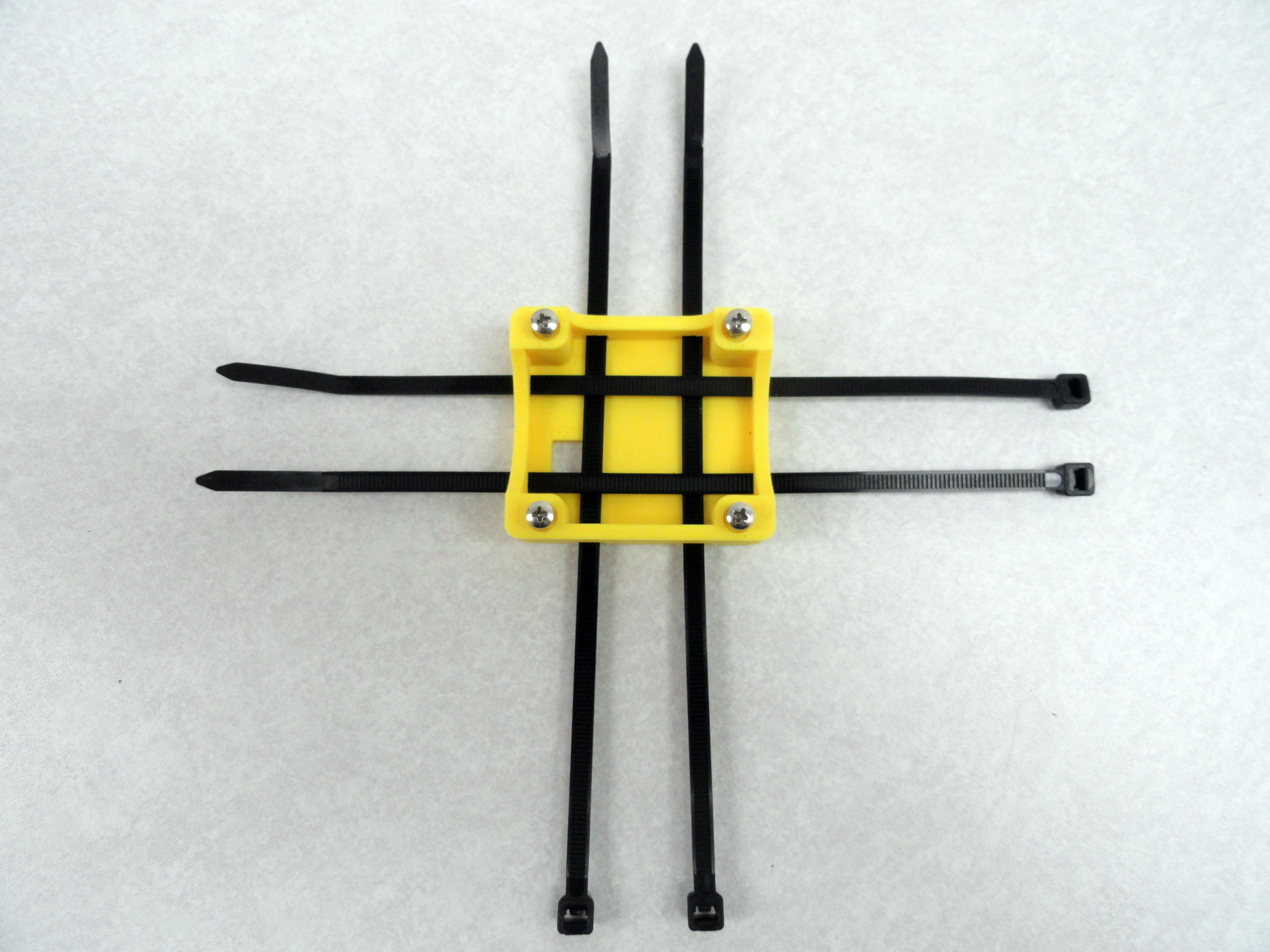
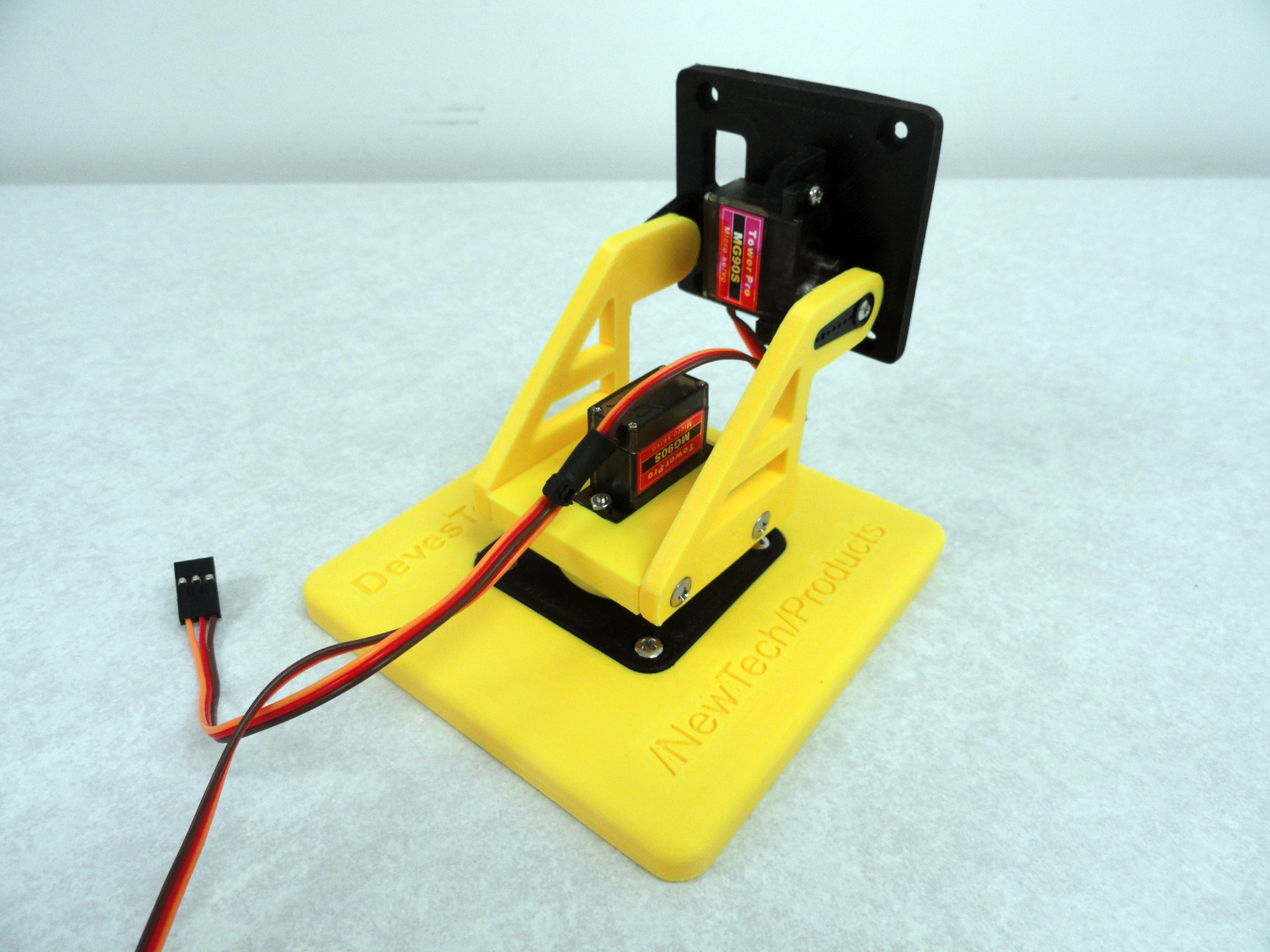
- We wanted a Dual Servo Gimbal for the MG90S and SG90S Mini Servos that was compact, yet solid. Most offerings have a weak point at the mounting base where one screw is holding up the entire assembly. Ours is designed with screws AND NUTS on all assembly points. The mounting propeller is bolted down and the system is designed to be very solid.
- The other offerings do not give a complete 0-180 degree movement on both axis'. This one gives you slightly more than a 180 degree range of motion on both axis'.
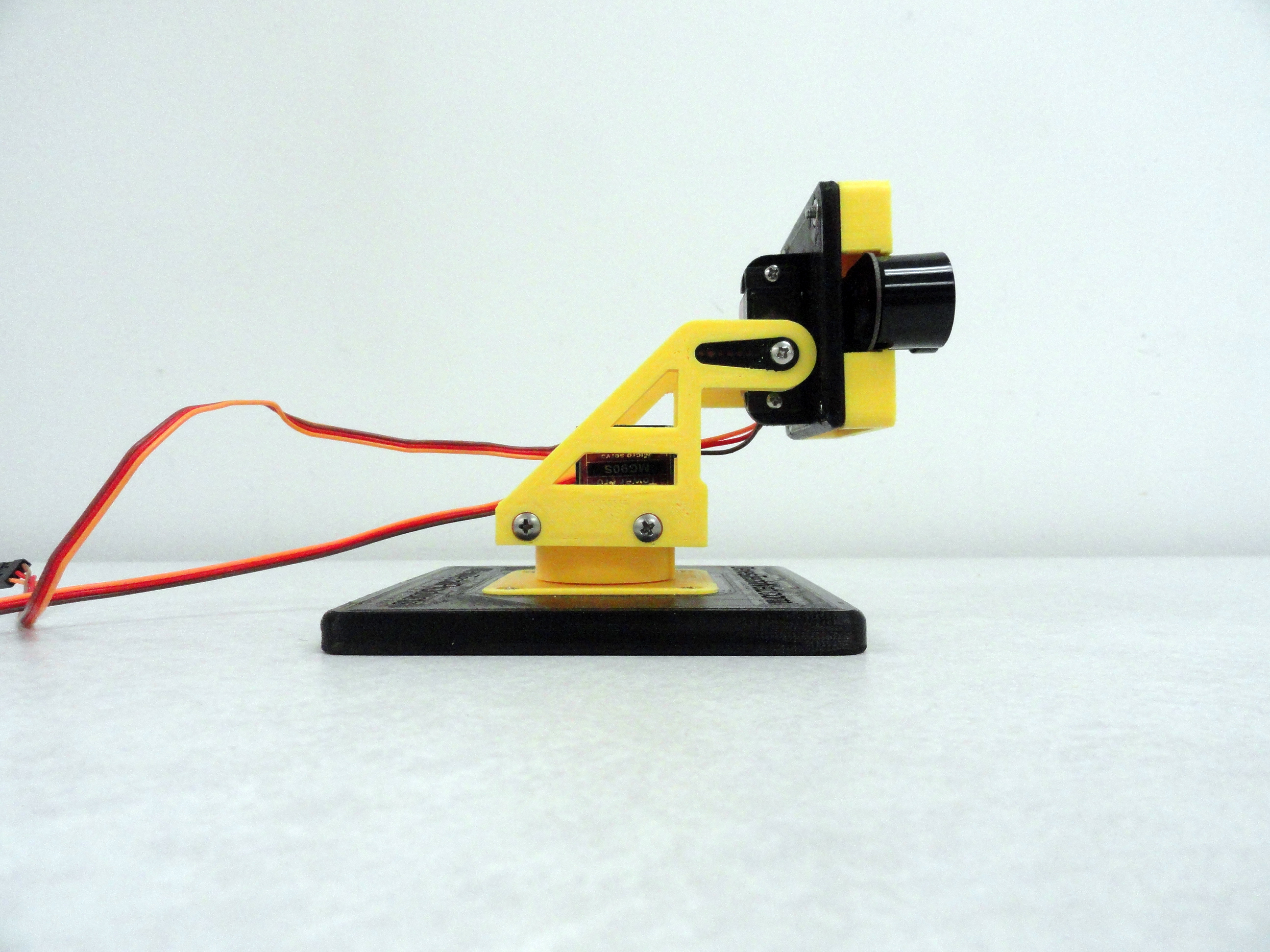
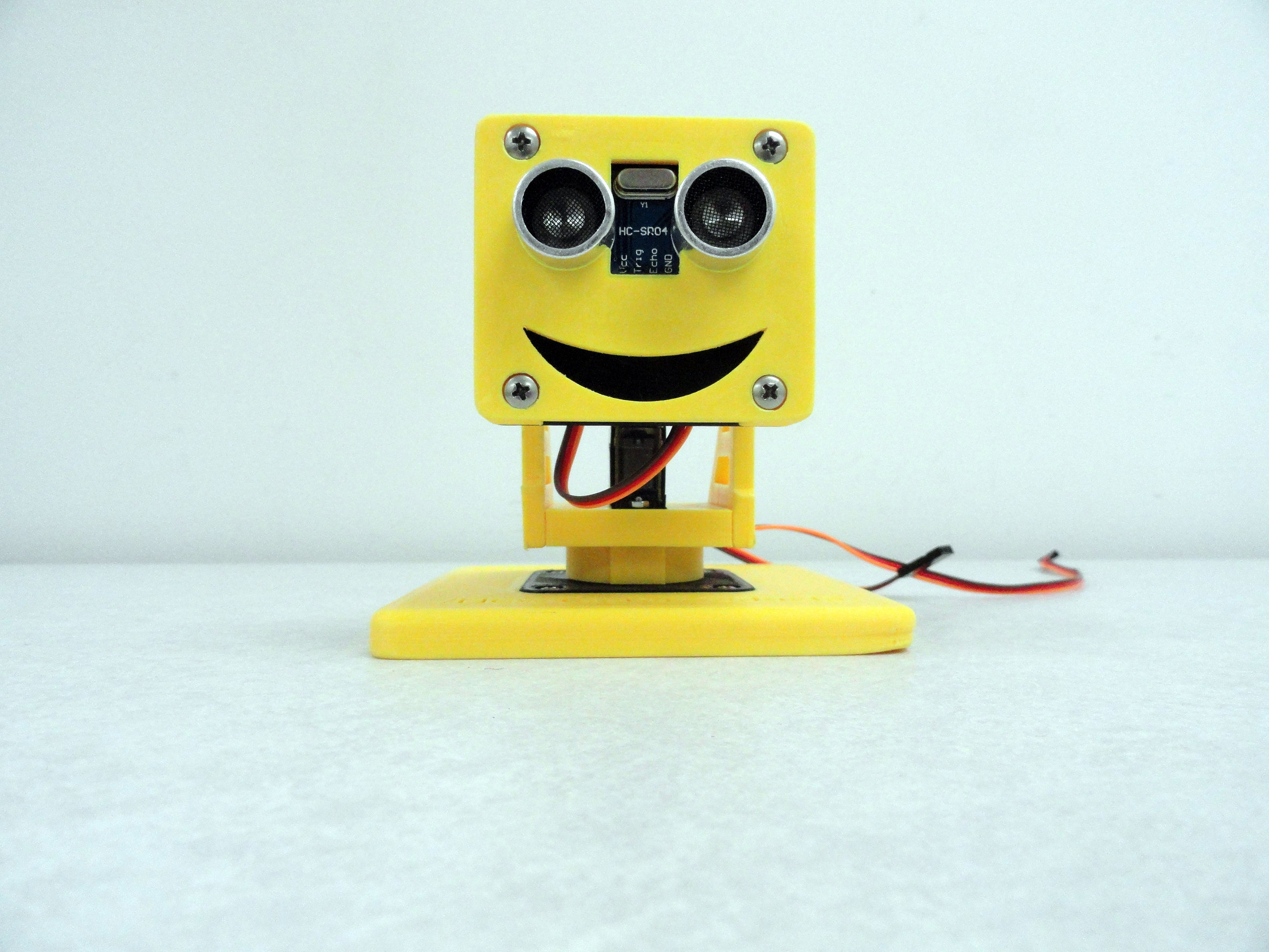
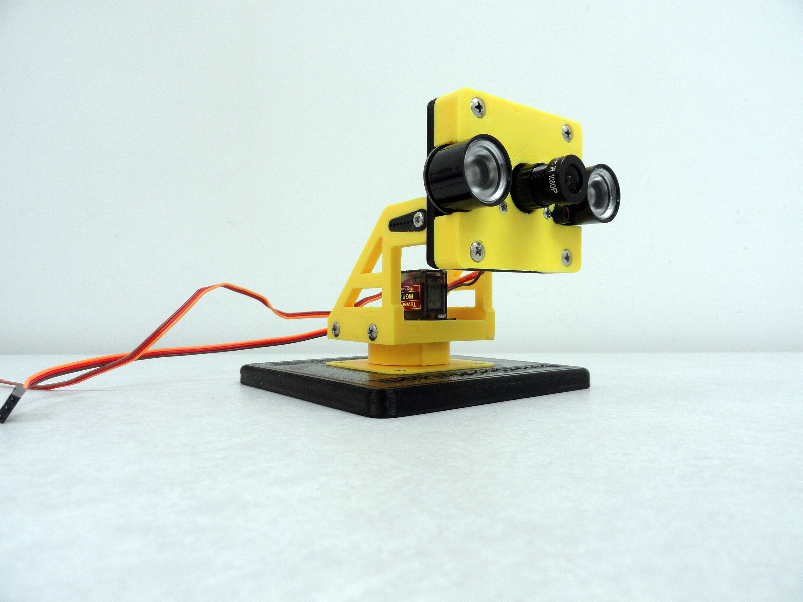
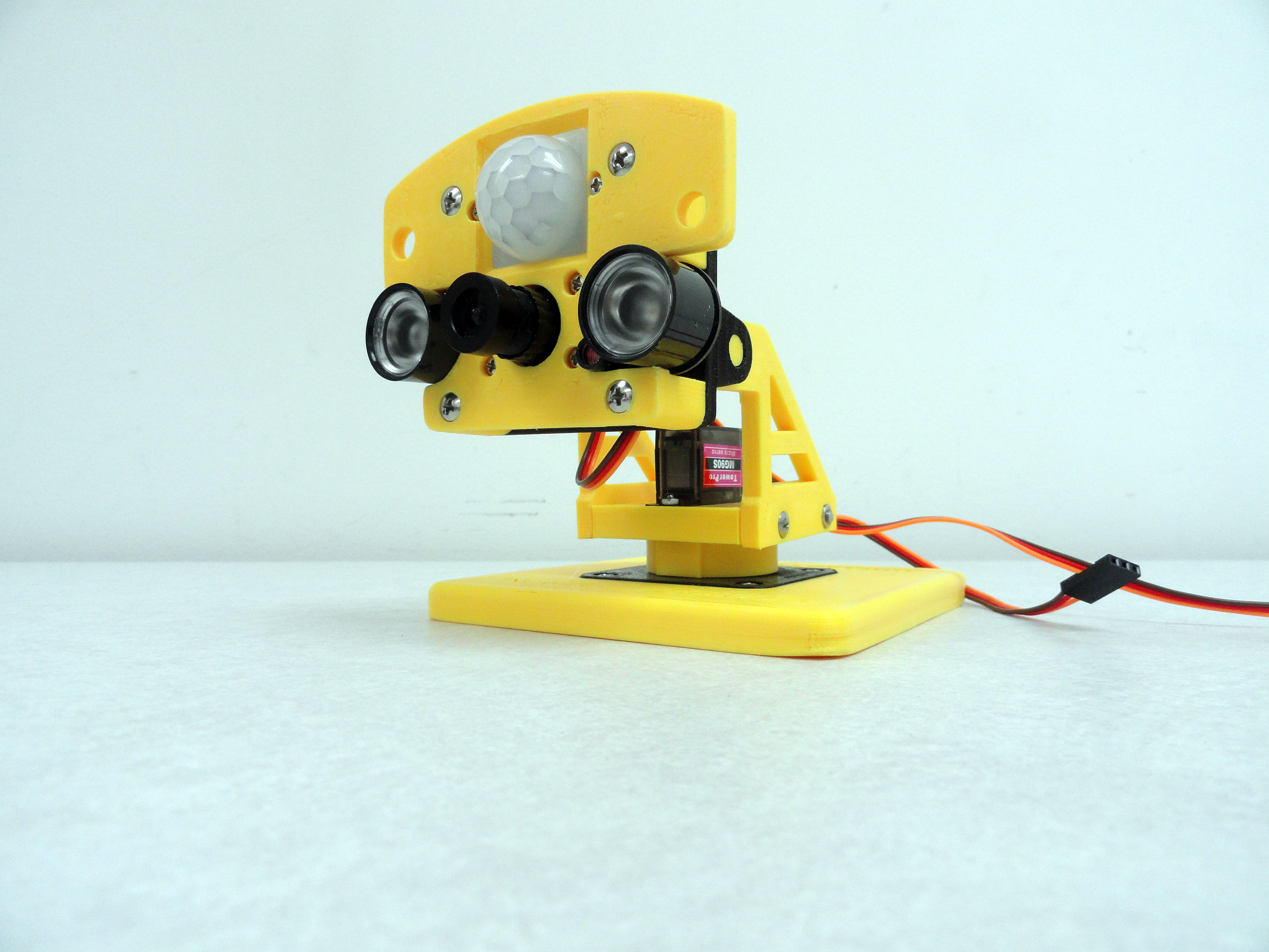
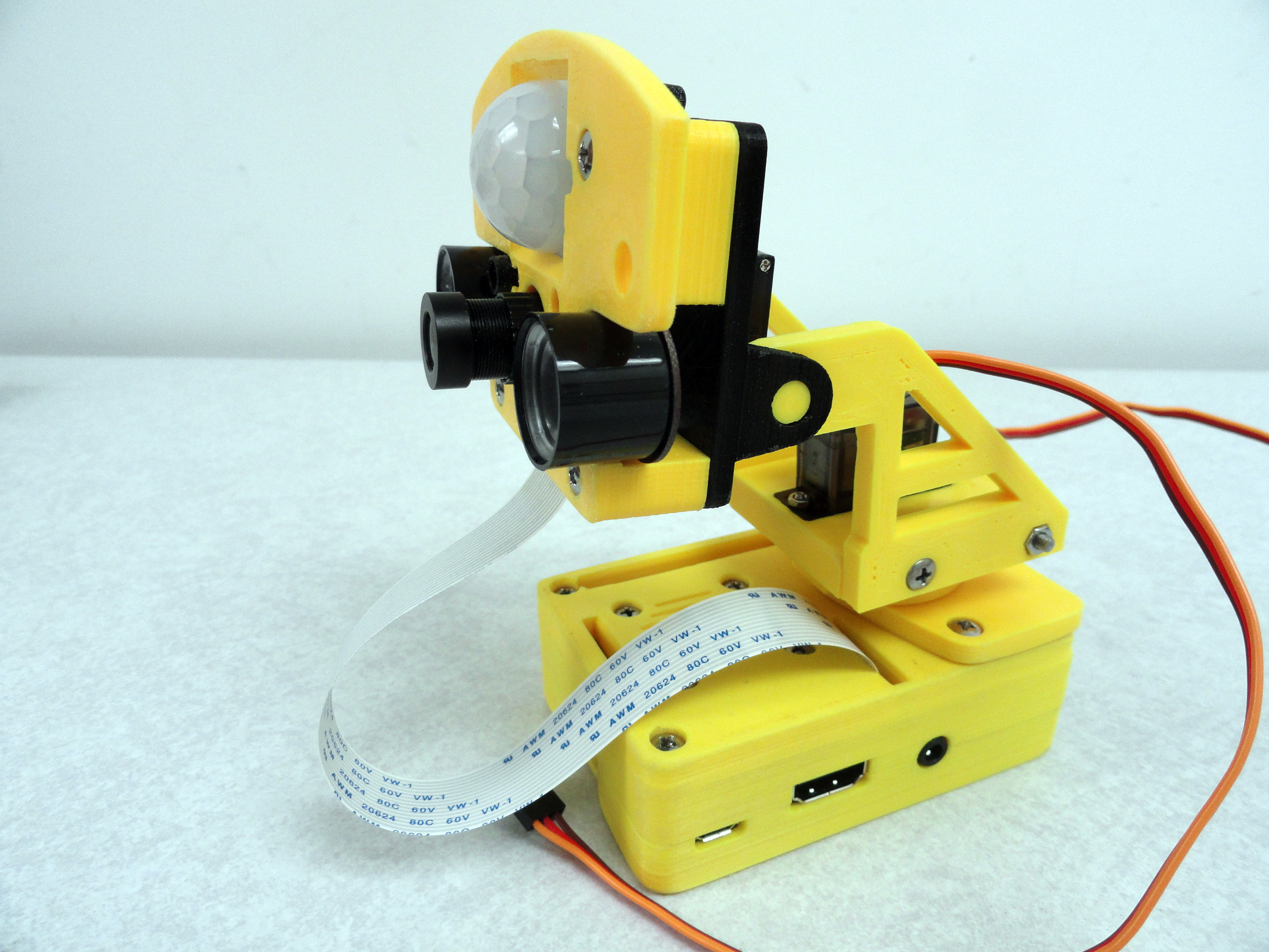
- We designed this as a "System", meaning we know you use your Gimbal for multiple purposes. Ours has accessory mountings for the HC-SR04 Sonar Sensor, OV7670 Arduino Cam, Raspberry Pi PiCam with (or without) IR, a Generic Mount, a PiCam with IR plus PIR Motion detection, and a complete Raspberry Pi 3 Model B enclosure WITH Mini Servo Gimbal Mount on top! In addition, we are working on PixyCam and Go-Pro mounts.

The Base Kit
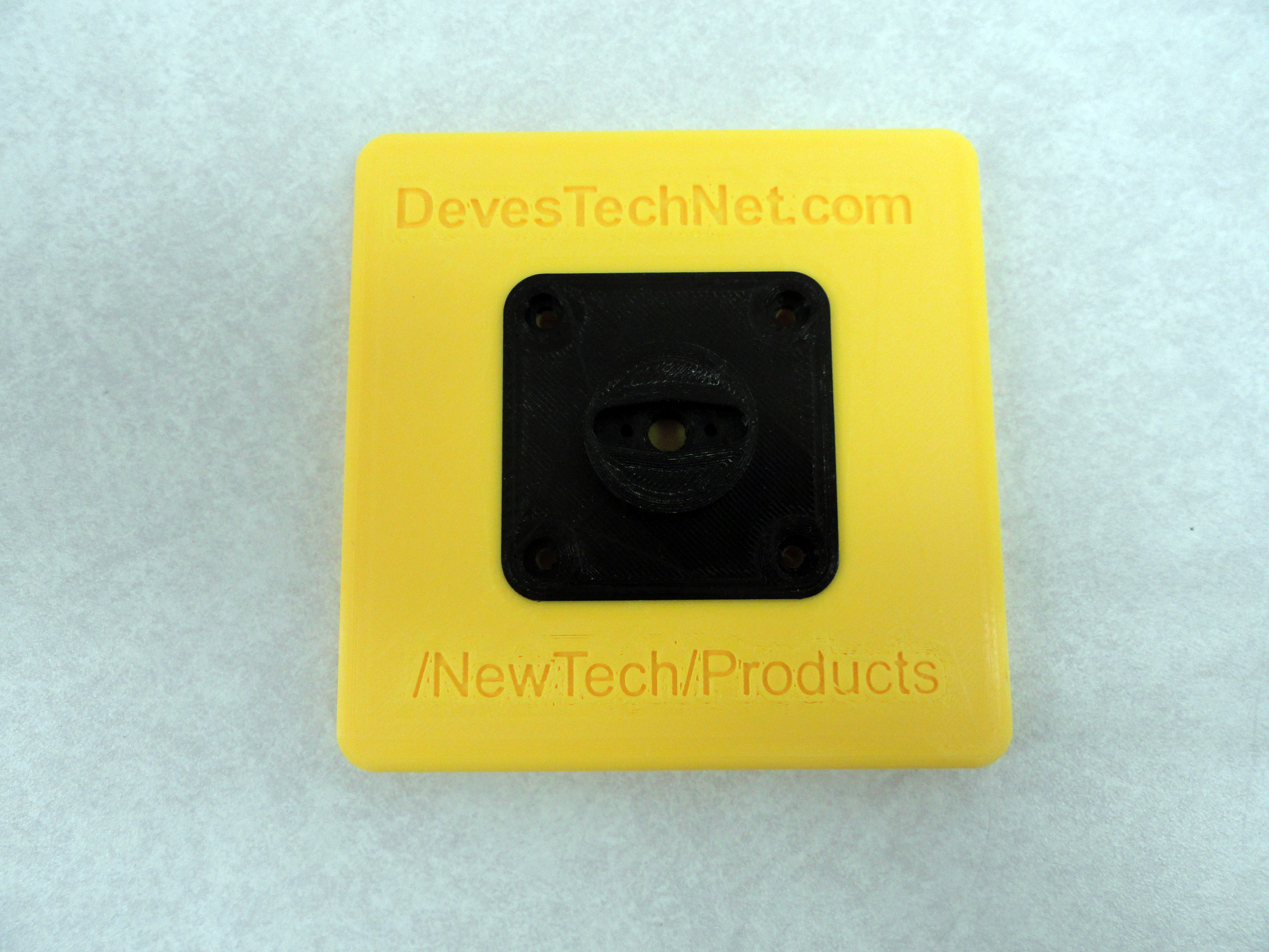
Included in the Base Kit is a 4" by 4" Platform to mount your Gimbal on. This provides for stability while testing your project. All
screws, nuts, etc. are Stainless Steel and provided in the kit. In the Base Kit you will find:
- The 4"x4" Platform mentioned above
- A Base Propeller Mount
- A Pan Servo Mount
- Left and Right Side Rails
- A Tilt Servo Mount
- One Accessory Mount of Your Choice
- All of the required associated hardware in Stainless Steel.
The Base Servo Mount uses four 3mm screws and nuts with a 6mm length and spaced 1-1/2" square. The Pan Propeller is mounted using 2mm x 8mm screws and nuts. Two holes are drilled using a #46 drill bit to accommodate the screws which are placed in hole #2 (from the center) on the propeller. Trim the Propeller by cutting it at the #4 hole (from center) on each side. No other modifications are needed. This is necessary because the propellers (and Servos) do not come with the Base kit.
Assembling Your New Super Servo Gimbal
Step One: Please follow these instructions carefully. Trying to guess at the next step will have you taking it apart again! The 4" x 4"
(approx. 101mm) Platform has 4 mounting screws that are 3mm x 6mm with accompanying nuts. This pattern is to accommodate
the Gimbals Base pattern which is 1.5" (38mm) between adjacent holes. not mount the Gimbal Base to the Gimbal Platform until Step 5.
Do not overtighten the screws! Since they are all captured, they aren't going anywhere.
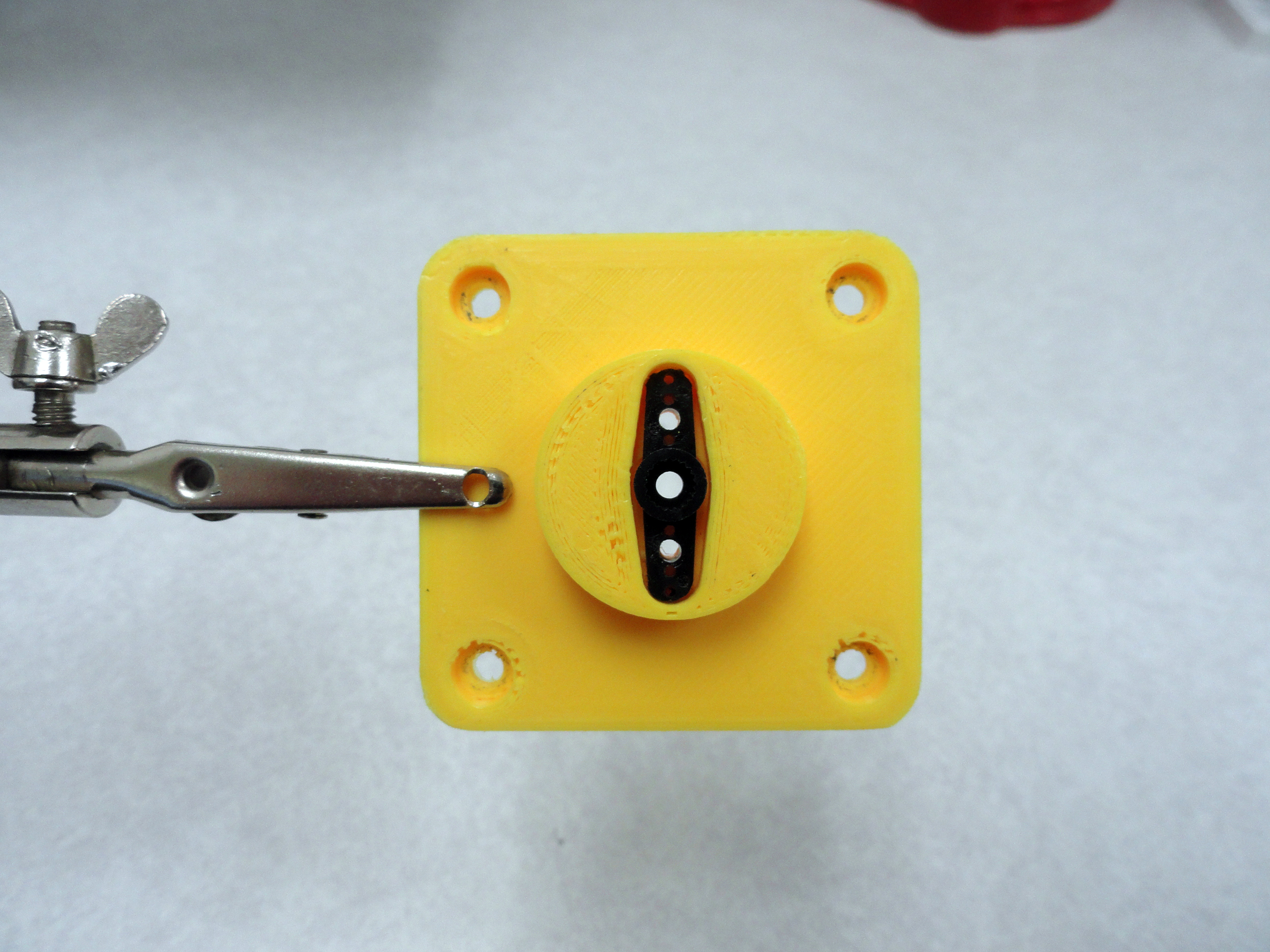

Step Two: This is the hardest part and only because the Servo's are not included in the Kit. Cut the Servo's Propeller at hole #4 on both sides, then round the edges to fit so the Propeller fits nicely inside the Base as shown. With the propeller in place, drill a hole using a #46 drill bit at hole #2 on both sides. This will allow the 2mm x 8mm screws and nuts to hold down the propeller. This feature is one of the things that set our offering apart. It makes for a VERY solid Gimbal! In a pinch you can use a 3/32" drill, but #46 is better. Install the 2mm by 8mm screws and secure with nuts on the bottom of the Base. Set the Base aside for now.
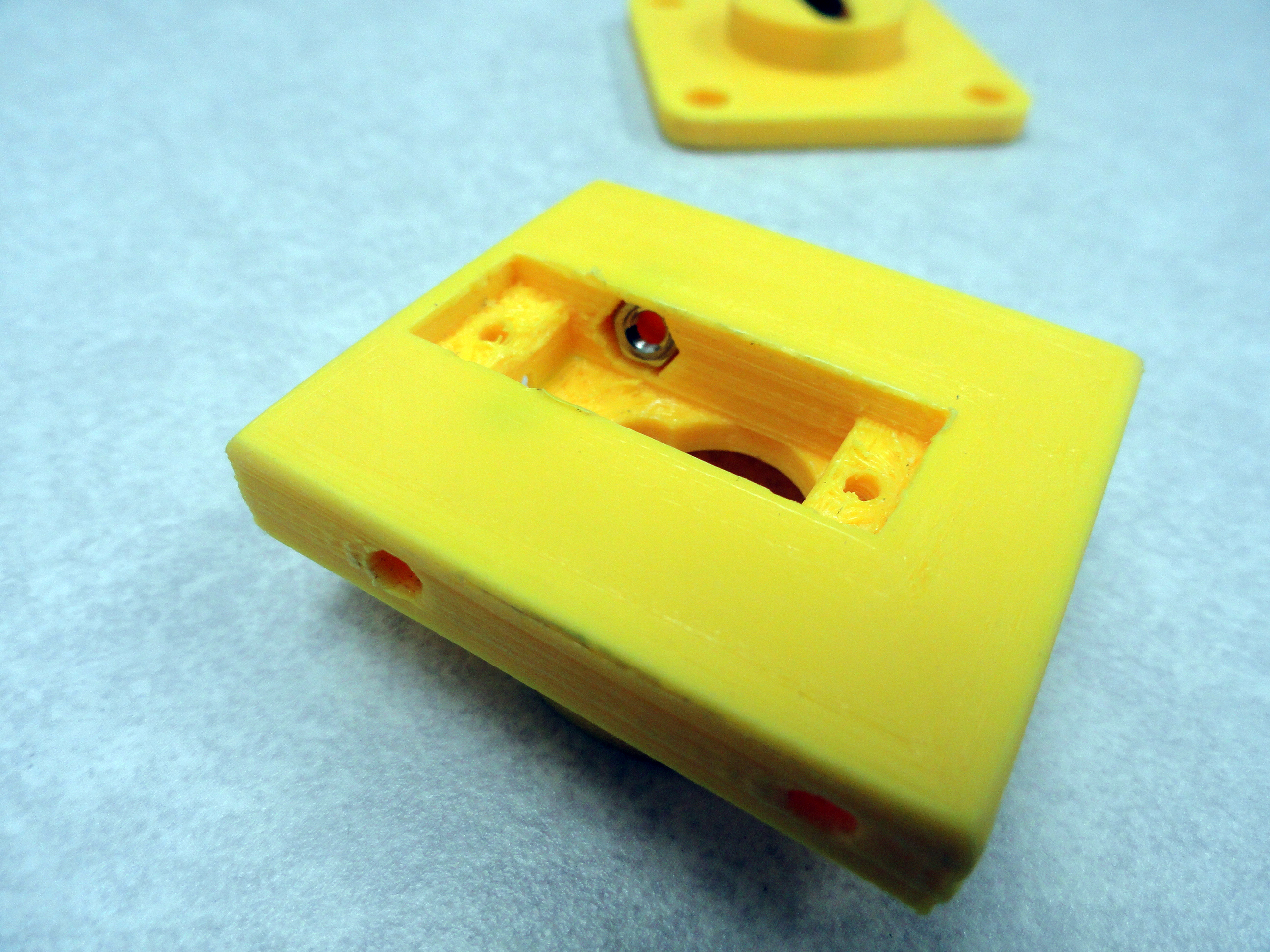
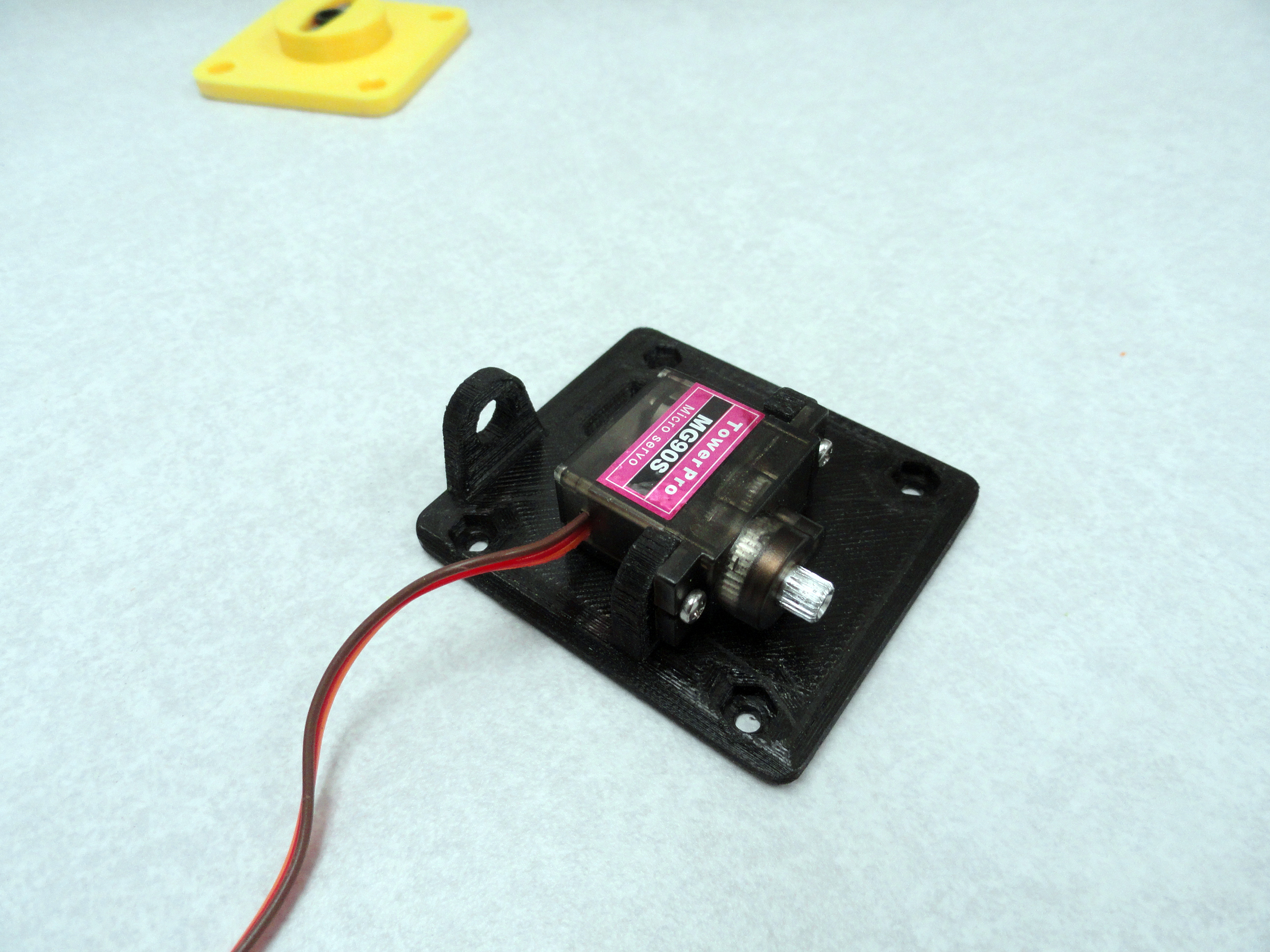
Step Three: Insert two 3mm Nuts into the Servo cavity as shown. With them inserted squarely, press the Pan Servo into position.
Notice the orientation of the Servo. It only goes on one way. Be sure to put the Nuts in first! Secure the Servo with two 2mm by 8mm
Screws with the Nuts on the Servo Side as shown.
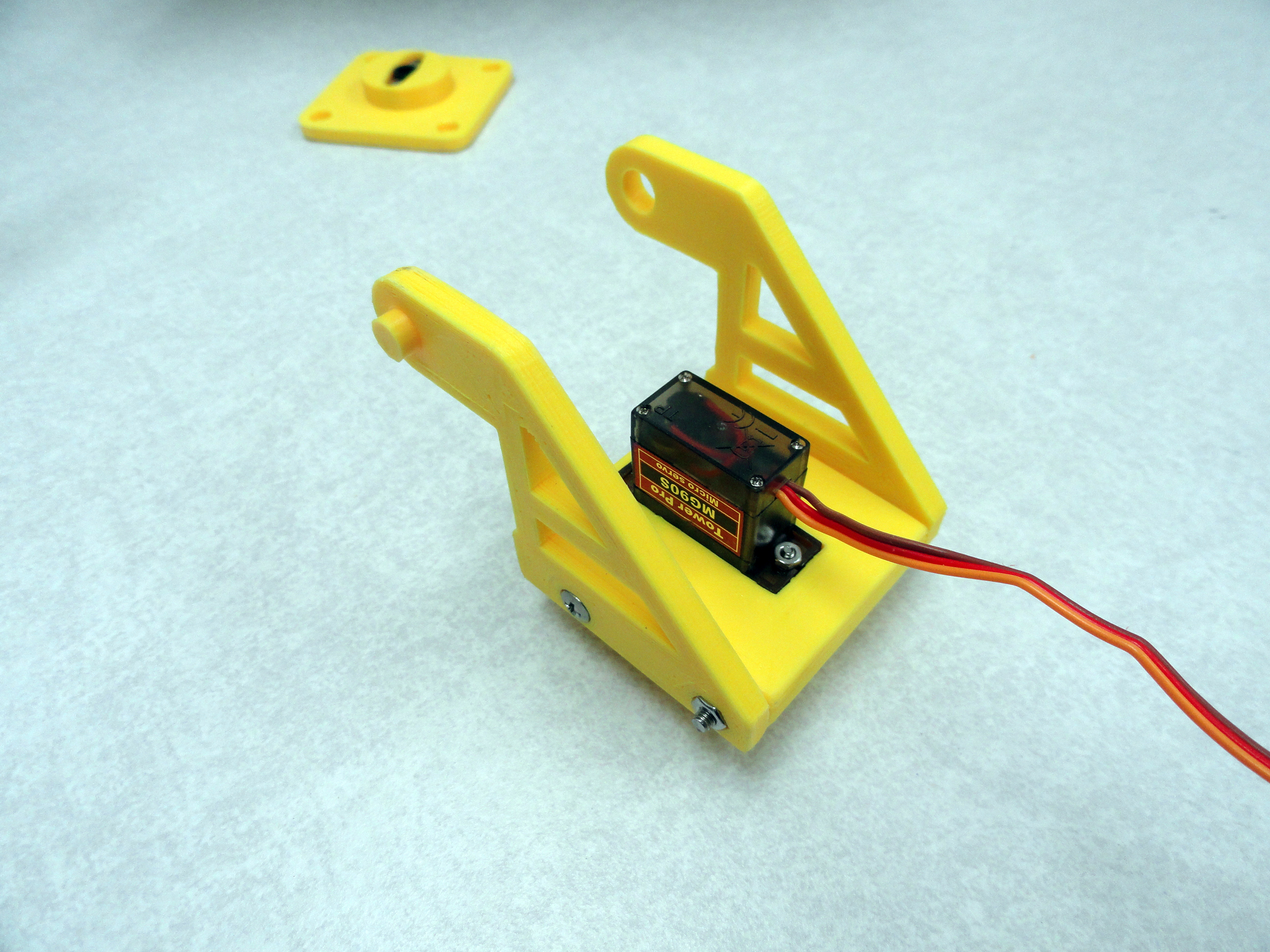
Place the side rails against the Servo Assembly so that the capture features face outwards as shown. The left and right are oriented
to properly go on only one way. Secure the side rails to the assembly with the long screw first with the Servo body between the rails.
This is the 3mm by 50mm screw with the 3mm nut in the capture cavity. With the long screw and nut holding the two rails to the Pan
mount, install the 3mm x 15mm screws into the side of the Servo Mount. They are long enough to grasp the nut but not long enough to
damage the servo. As shown. Do not mount the base yet!
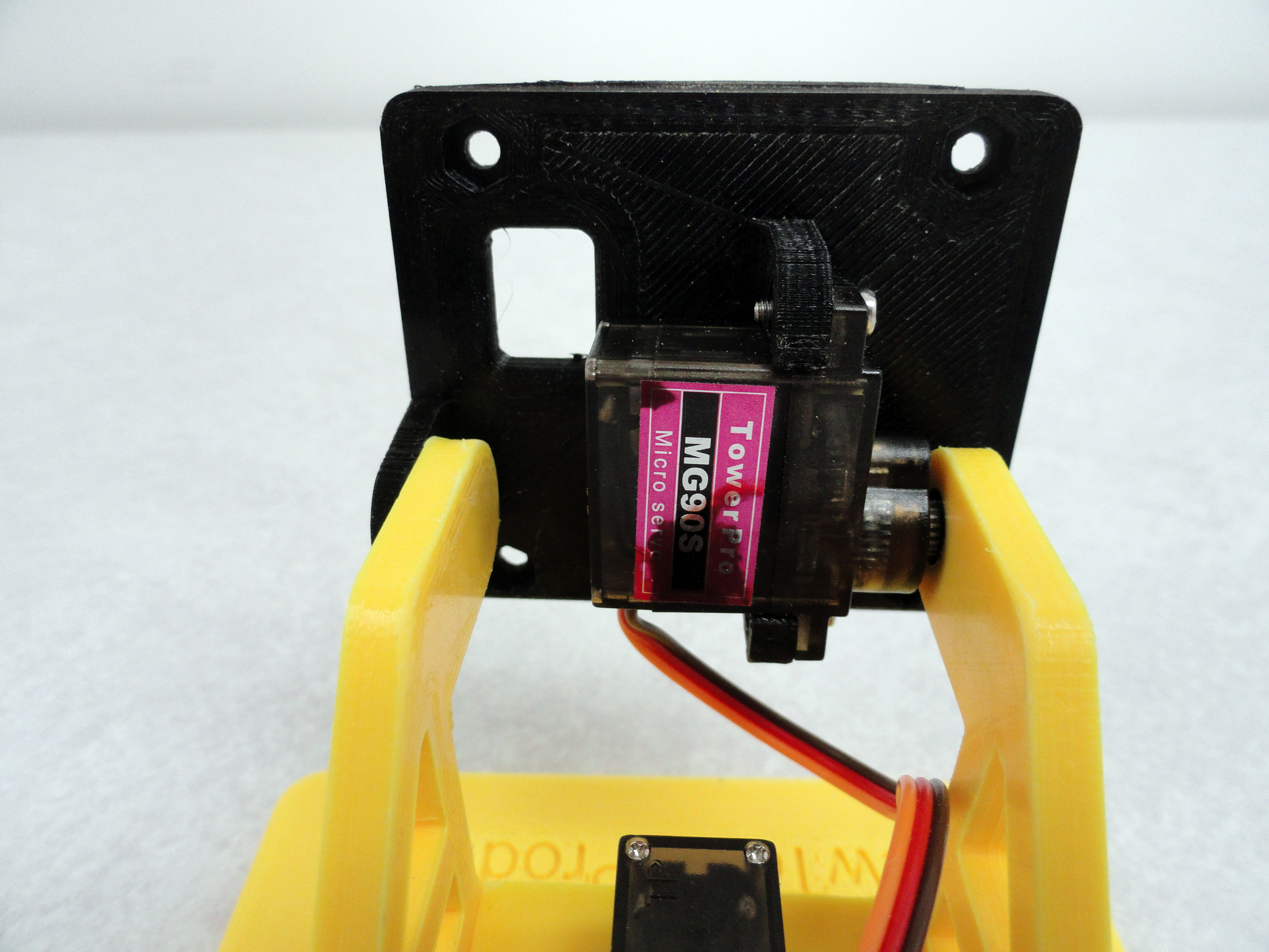
Step Four: The Left Side rail has the male connection to the Top Mount and the Right Side rail has the connection to the Servo.
Both are made to withstand stress and are very rigid. The Right Side rail accommodates the Tilt Servo Propeller which pops right into place
without modification. Secure the Tilt Servo to the Top Mount using the included 2 by 8mm screws and nuts as shown. Be sure to orient the
Servo Shaft to align with the opposite hole.
The tricky part is to push the Servo's into their respective Propellers in the proper alignment! On the Tilt Servo, I like to move the Servo
to one of its end stops, then place the Tilt Platform at the very end of its travel. You do not want to damage the Servo when you power it up
because it is trying to slam against one of the Gimbals natural stops. Test install the Servo and gently move it to where you expect it to go.
If it does not move 180 degrees smoothly, gently pull the servo out of the propeller and set it in again in a different position. Chances
are very good that even if you followed this instruction, when you actually power the Servo up, it will need to be re-aligned slightly.
Secure the propellers with the fine thread 2.5mm screws that came with your Servo's.
The Tilt Servo Mount is constructed to perfectly fit in between the rails with a hole cut out to thread wires through if you so choose. This
system will give you more than 180 degrees to adjust your servos to the angles of your choice. Our easy to use Arduino Servo Test Program will
make it easy to set the Servo Angles to your liking providing you have the Arduino IDE.
The next thing you will want to address is the proper movement of the Servo's on the Servo Gimbal. This is essential to its proper
operation as well as prolonged battery life. These hobby servos have a serious flaw in that they do not know where their limits are.
This presents us with an opportunity to custom set each servo so that the servo doesn't cause a high amperage situation. Do NOT think
the servo's automatically know 0 and 180 degrees! The following program will guide you in setting them up. Read the comments at the
top of the program to understand how it works. Unzip and place in your Arduino/Sketches folder:
Arduino Dual Servo Calibration and Tester
Once you have both Pan and Tilt Servos set so that the sweep is in the center and there are no odd noises coming from the
Servo's when they reach their limits, you are good to go.
 Step Five: The top mount has 4 mounting holes spaced 1-5/8" (41mm) apart. These holes accommodate any of the Mounts we have created.
Secure your chosen device mount using the included 3mm screws and nuts. With the entire assembly completed, you can now mount the Gimbal Base
to the large Gimbal Platform for added stability. Otherwise, enjoy your new acquisition and let us know how we can improve this product!
Check out the Video Short:
Mini Gimbal: The Movie!
Step Five: The top mount has 4 mounting holes spaced 1-5/8" (41mm) apart. These holes accommodate any of the Mounts we have created.
Secure your chosen device mount using the included 3mm screws and nuts. With the entire assembly completed, you can now mount the Gimbal Base
to the large Gimbal Platform for added stability. Otherwise, enjoy your new acquisition and let us know how we can improve this product!
Check out the Video Short:
Mini Gimbal: The Movie!You can Purchase one of these Gems on our Buy-It-Now page!