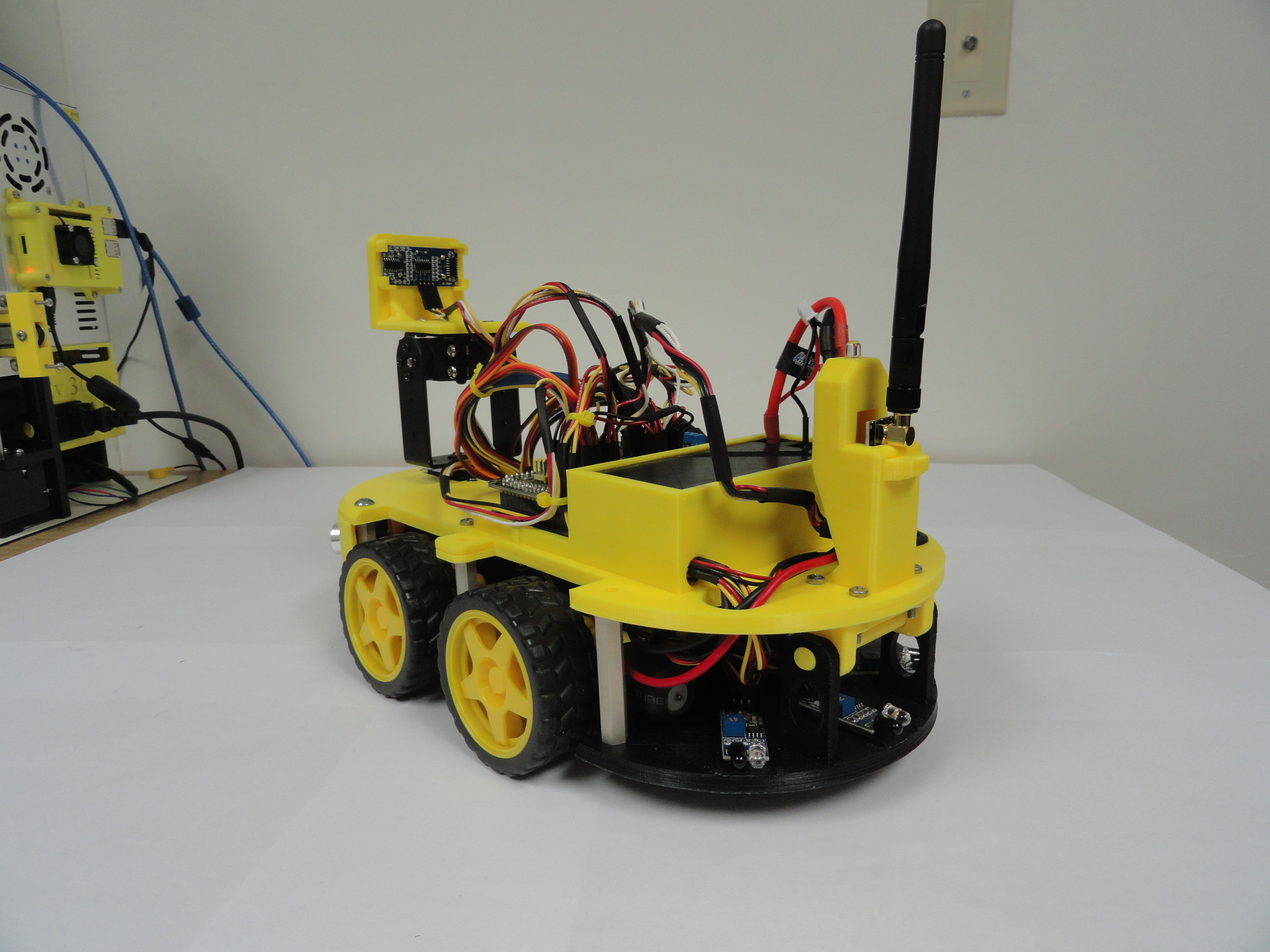
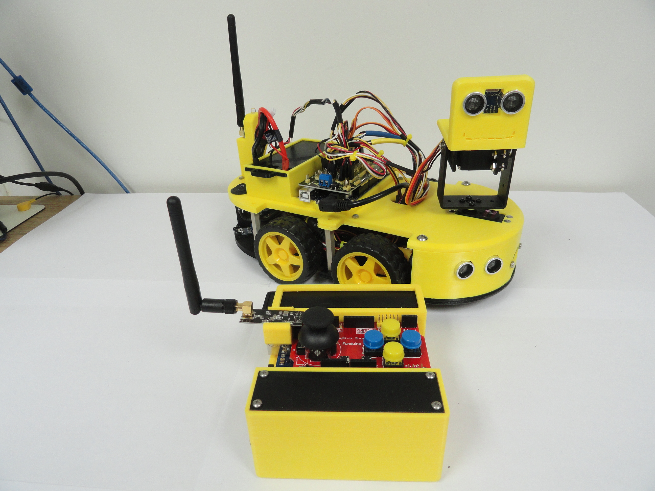
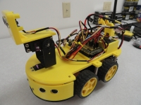
Introducing The Super SmartCar
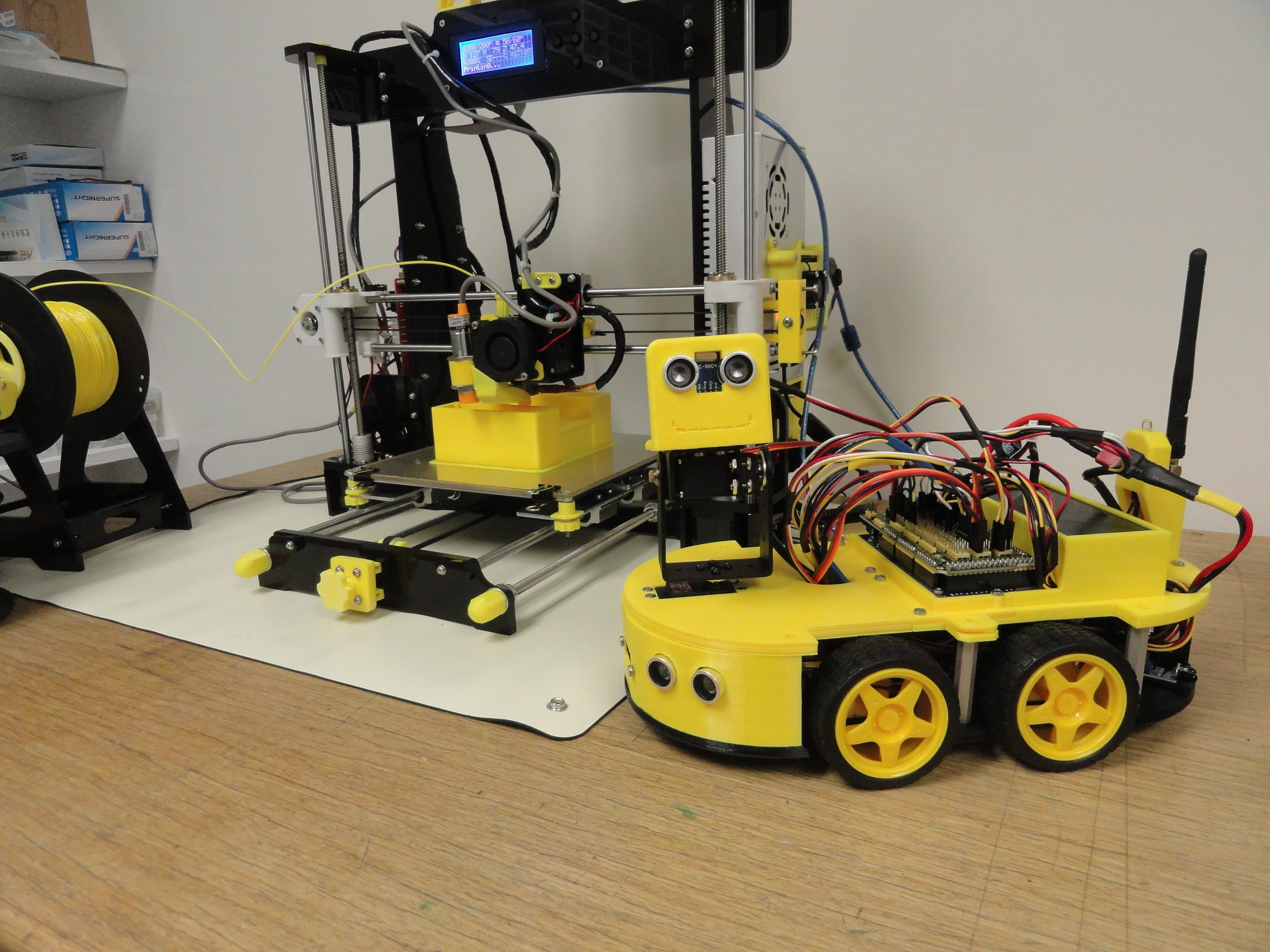
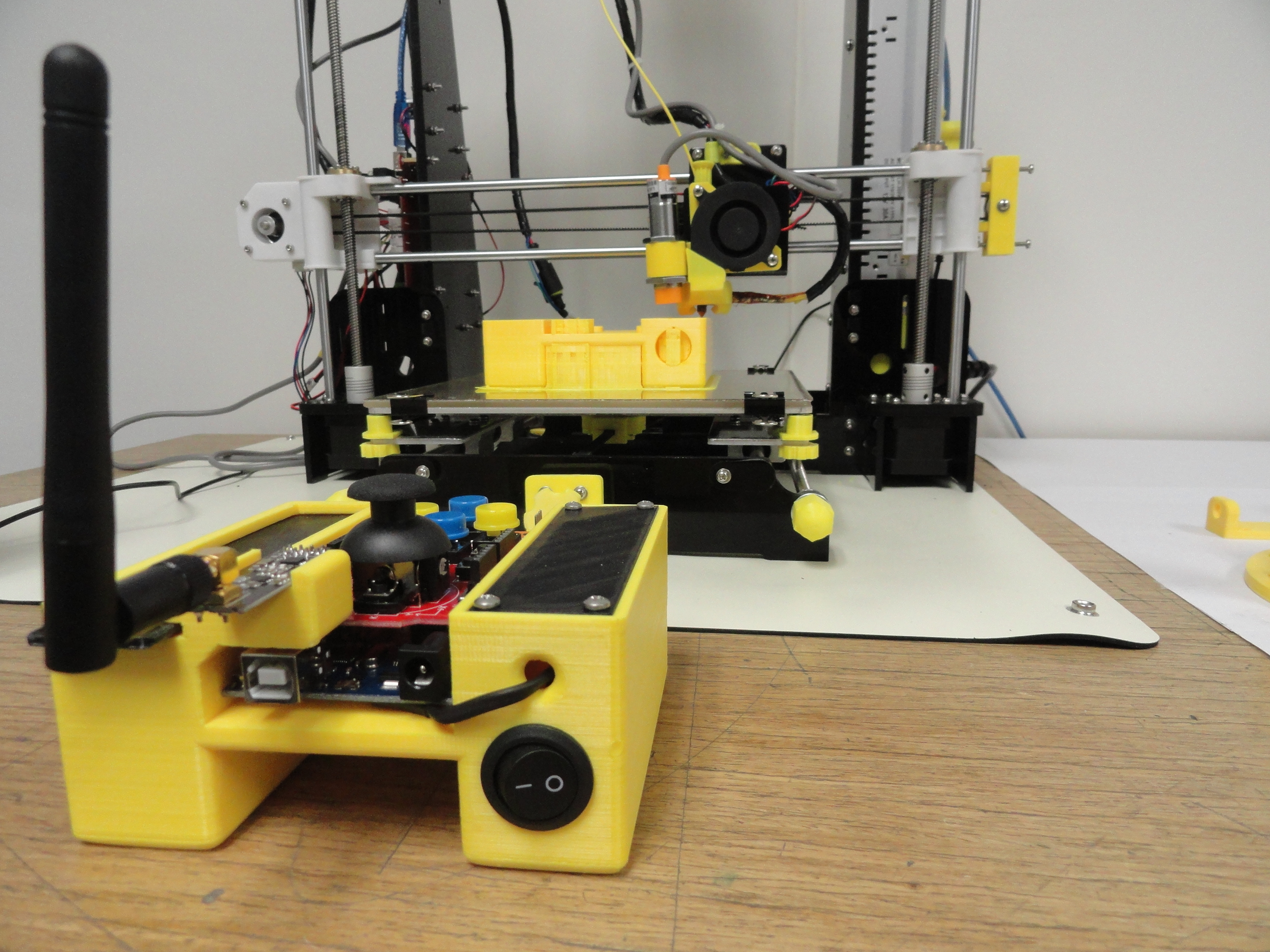
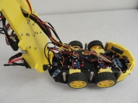
With the wonders of 3D Printing, we are able to introduce a whole new chassis system for the standard Arduino SmartCar as sold by Ebay and Amazon Dealers. These Smart Cars are for Arduino enthusiasts to learn how sensors, servos, motors, etc work powered by the intelligence of the Arduino Micro-Controllers. It takes lots of time and patience to build this new wonder, so take your time and fully understand the following instructions. The 3D Printed chassis is printed at the highest resolution available and each of the four main parts takes approximately 30 hours to print! The Remote Control Box takes 54 hours!
The differences between the other systems and this design are:
1) The idea of using Bluetooth so that you can control the car via Smart Phone was limited to people who have Smart Phones, and the Programs that were available for the control were very limited. Unless you are an Android programmer, your options were (very) limited. In addition, the IR remote method is very limiting in distance. This Super SmartCar uses the much longer range NRF24 Radio Transceiver system allowing us to use standard switches, thumb controllers, etc to give us unlimited functionality using Arduino (C+) programming exclusively. This requires a second Microcontroller, but worth the extra effort. Check out this site for specs on the NRF24. It has a normal range of 800 meters or over 2600 feet! These little radios are used a lot on Radio Control Airplanes as well.
2) Many more sensors are used for Collision avoidance, Tracking, etc. Sporting three HC-SR04 Sonar sensors (range from .75 inches/2cm to 157 Inches/4m), one of them on a dual axis gimbal using the much more reliable larger MG995 Servos, One long range Sharp 2Y0A21 Proximity Infrared forward looking sensor (10 Inches/10m to 30 Inches/80m), three IR rear sensors facing 35 degrees away from each other for overlapping coverage thus better obstacle avoidance coverage with a range of .75 Inches/2cm to 12 Inches/30cm and 3 tracking sensors facing down for sensing black track tape. This arrangement can even sense an upcoming staircase and stop the car before it takes the fall!
3) The dual motor MOSFET controllers used by the standard Smart Car's are used with the difference being, we do not share a single (Dual) Mosfet controller among 4 motors, rather, we use TWO dual Mosfet controllers so that each motor has its very own control channel! This allows much more flexibility in programming movement.
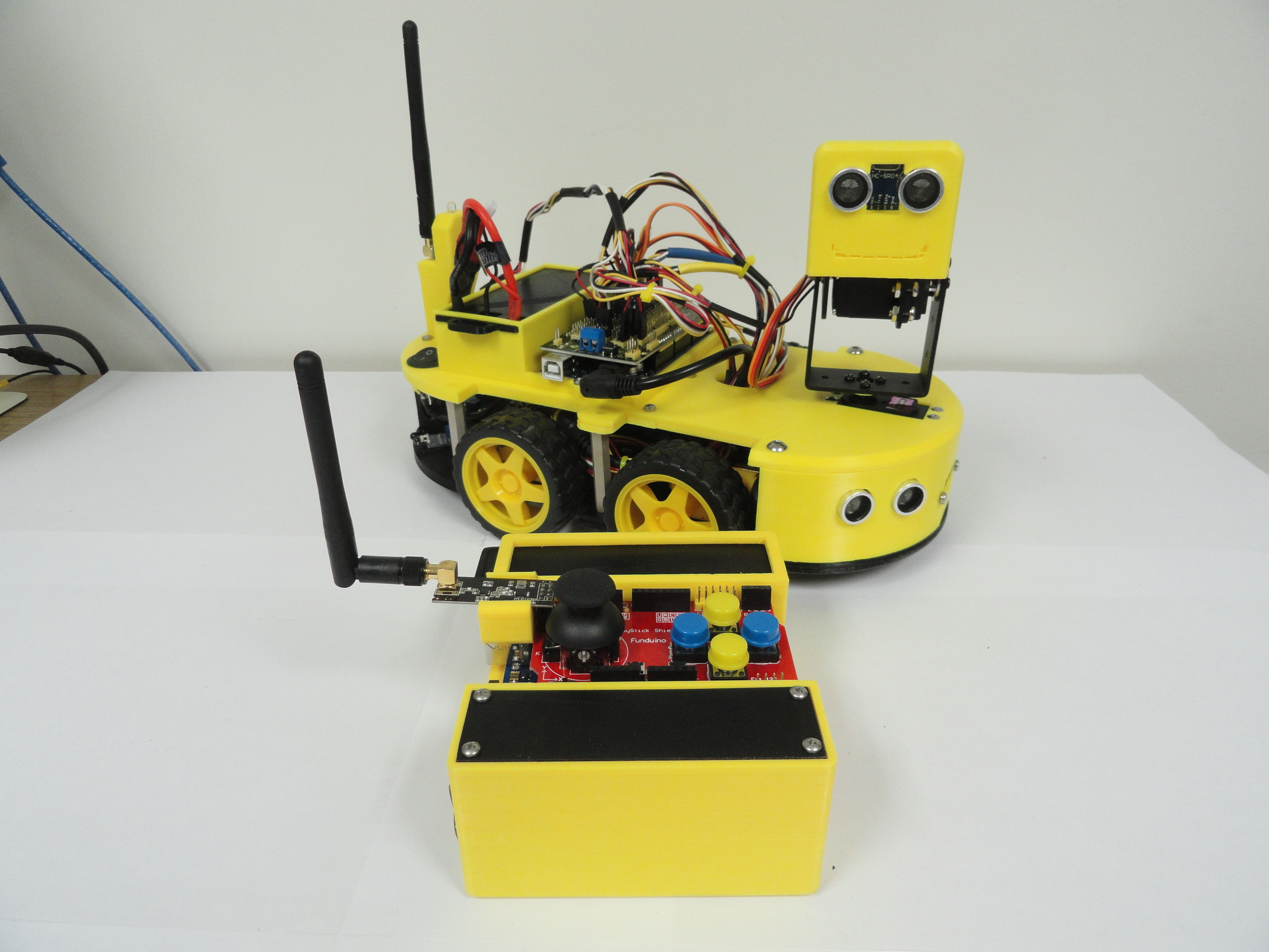
4) The Arduino Uno is replaced by the much more capable Arduino Mega 2560. We needed more PWM pins, more digital pins and more of everything and this solved the problem nicely. Using a Keyes Mega Sensor Shield, we can use Dupont Connectors to plug everything in. This gives us better connectivity and less soldering. The second Arduino used on the Remote Control side of things is still using an Arduino Uno and to control things we use a Funduino Joystick Controller Shield. It will do nicely for the time being having a thumb controller with switch for X and Y and 6 button switches for more connectivity. A 3D printed Remote Control Chassis keeps the battery, switch and controller together neatly.

5) The power system sports a 5000mAh 7.4 Volt Lipo Battery for the Super Smart Car, and two 18650 rechargeable batteries for the Remote Control. This combination gives very long service between charges.
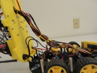
6) The design of the new Super Smart Car incorporates a hinged top for easier access to the bottom level where the Mosfet controllers and lower sensors reside. The battery is completely encased in its own battery box and a seperate toggle switch is incorporated into the chassis for easy power-up.
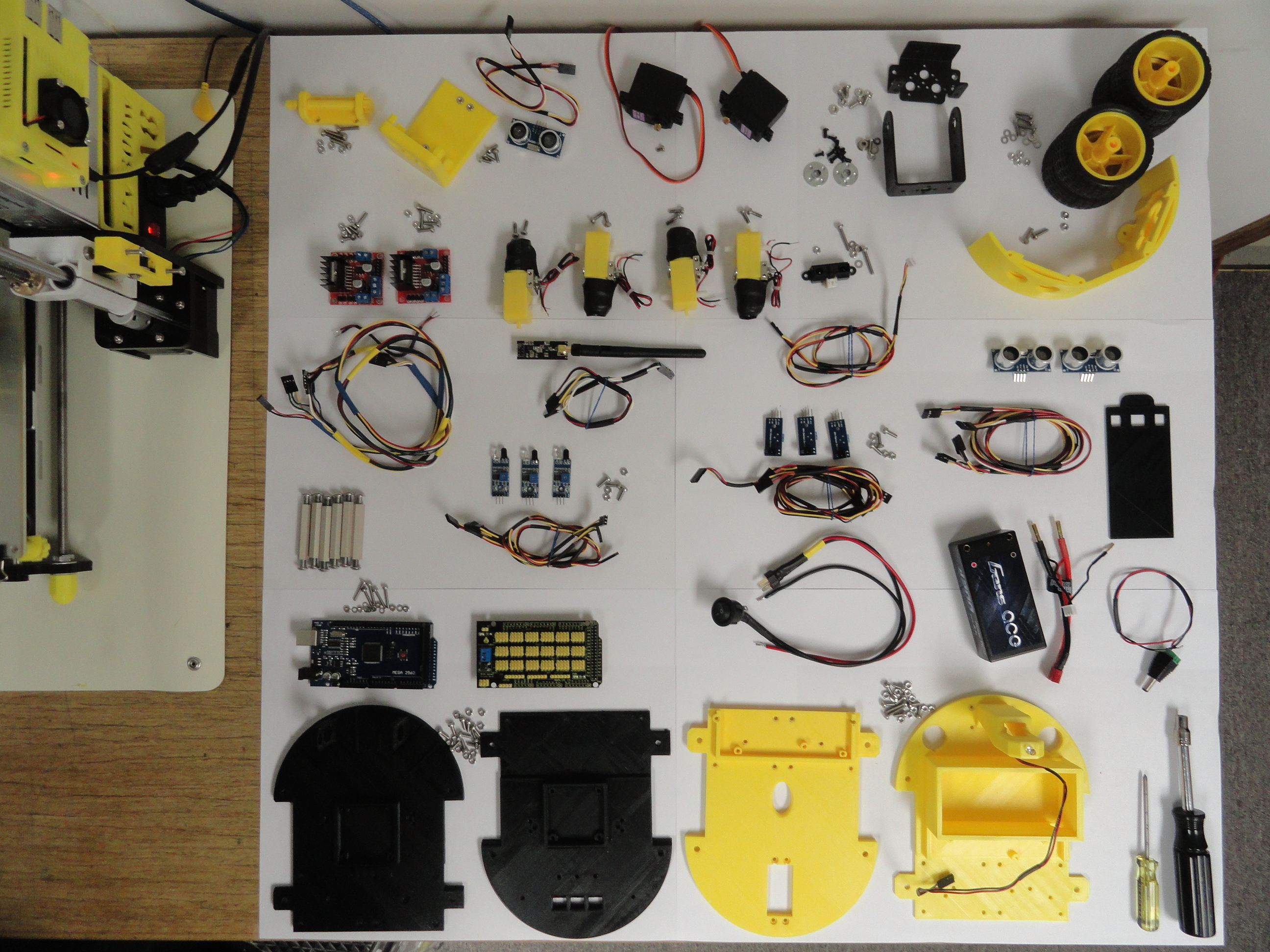
Complete Parts Listing (mostly available on Ebay) Search for newer listings.
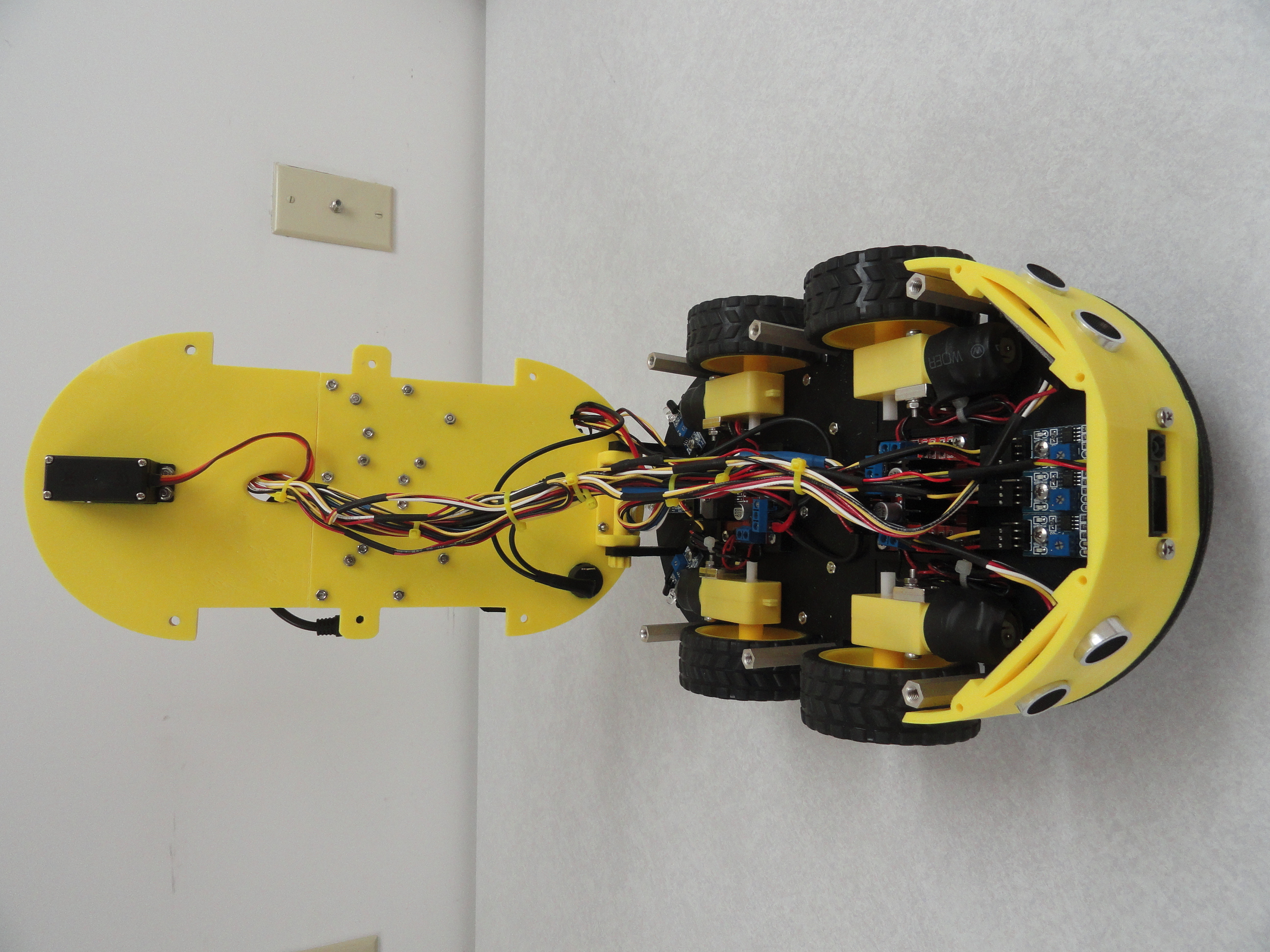
- Super SmartCar Chassis System - Kit includes 4 'halves' that when put together provide two levels, 1 Hinge Bracket with Hinge Bolt, Battery Case Cover, Front Fascia, and Remote Control Chassis with battery and switch covers. See Buy Now Instructions at the end of this Instruction.
- Two MG995 Heavy Duty Servos
- One Dual Axis Gimbal Bracket System
- One GENS ACE 5000mAh 7.4V 60C 2S2P Hardcase Lipo Battery Shorty Pack
- Two NRF24 Long Range Transceivers with Antennas
- One 3mm White LED Generic
- Three HC-SR04 Sonar Range Sensors
- Three IR Barrier Sensors
- Three IR Tracking Sensors
- One Sharp 2Y0A21 IR Front Facing Proximity Sensor
- Two Dual H Bridge LM298N Mosfet Motor Controllers
- Four 1.48 Geared Motors with Wheels/Tires
- Arduino Mega 2560
- Keyes Mega Sensor Shield
- Arduino Uno
- Two 18650 Rechargeable Lithium Batteries
- 18650 Battery Case with Switch
- Two Toggle Switches (one for the Car and one for the Remote)
- Dupont Wire Connector Kit
- Funduino Joystick Controller Shield
- Misc Stainless Hardware. Mostly 3m x 0.05mm Nuts, Bolts, Washers. (best resource is McMaster-Carr.com)
- Imax B6 Charger for the Cars Battery
- Imax B6 Charger Power Supply
- Charger for the 18650 Remote Batteries
Detailed Assembly Instructions

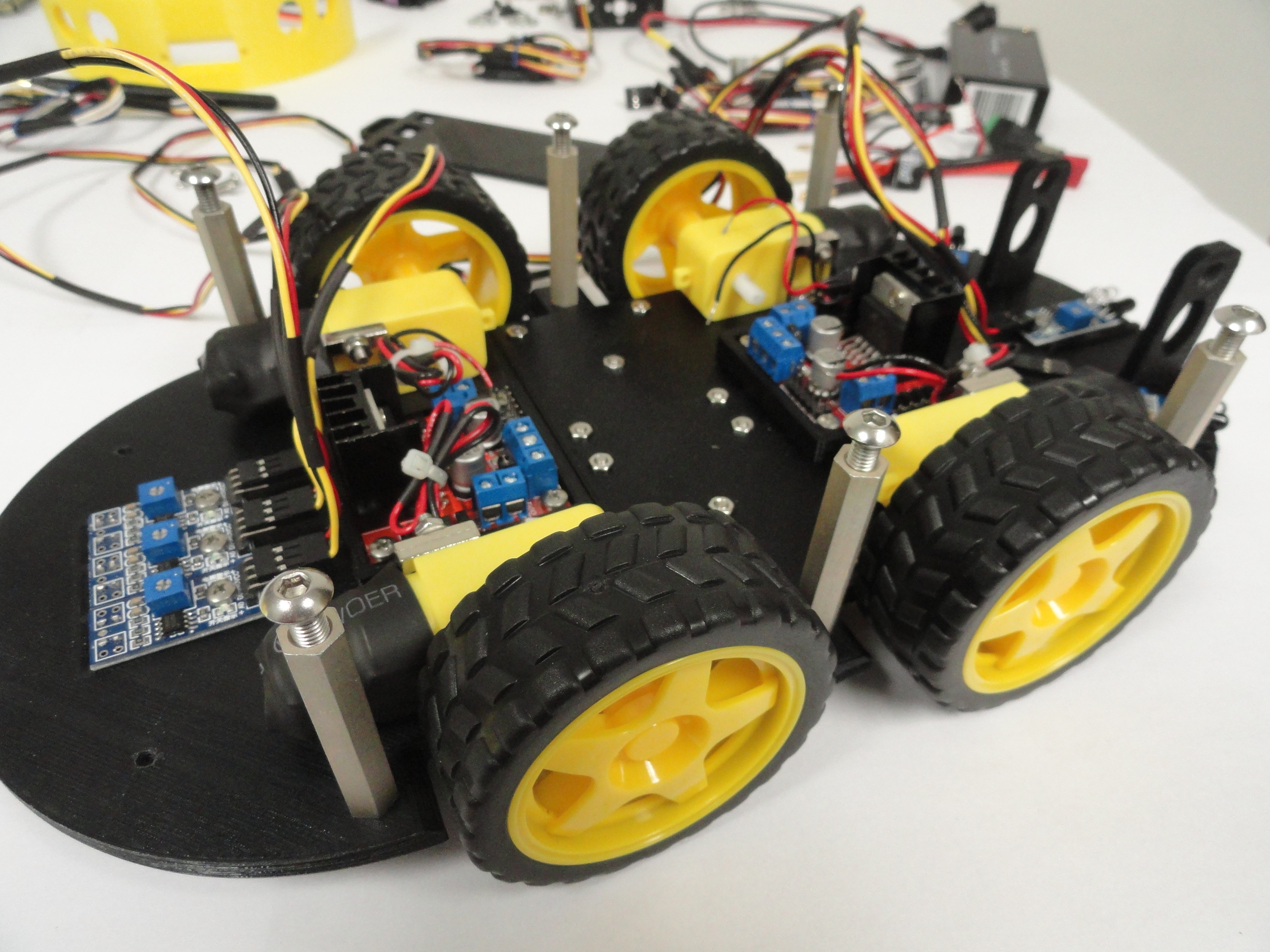
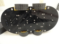
1) Bolt together the Chassis parts. Start with the Black Front and Rear Bottom Pieces. They are made to overlap each other, then 10 3m x 8mm screws hold them together very securely. Do not overtighten! There are nut captures for most of the assembly that can strip out so just make them snug. Tighten them so that they bottom out in the capture space, but no more. The heads of the screws are under the car with the nuts being on top (bottom tier only). Being American, I noticed these metric 3mm nuts have a standard 7/32 hex size. I use a 1/4 drive nut driver handle. The top pieces are held together with 8 of the 8mm length screws and 2 16mm longer ones on each side of the Arduino cavity. The screws are separated in the kit for easy identification. All nuts and screws are 3m x .05mm thread size and all stainless steel.
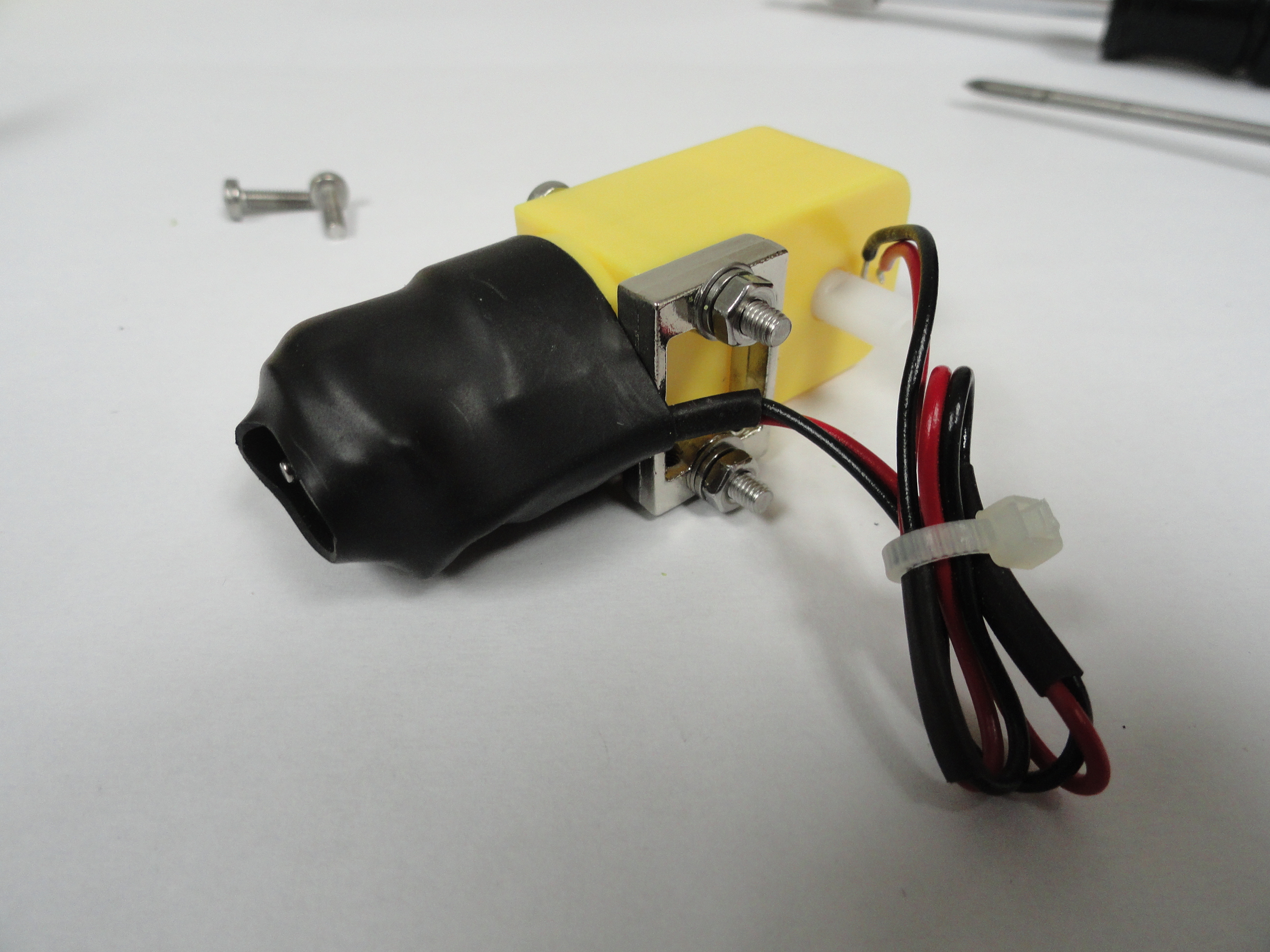
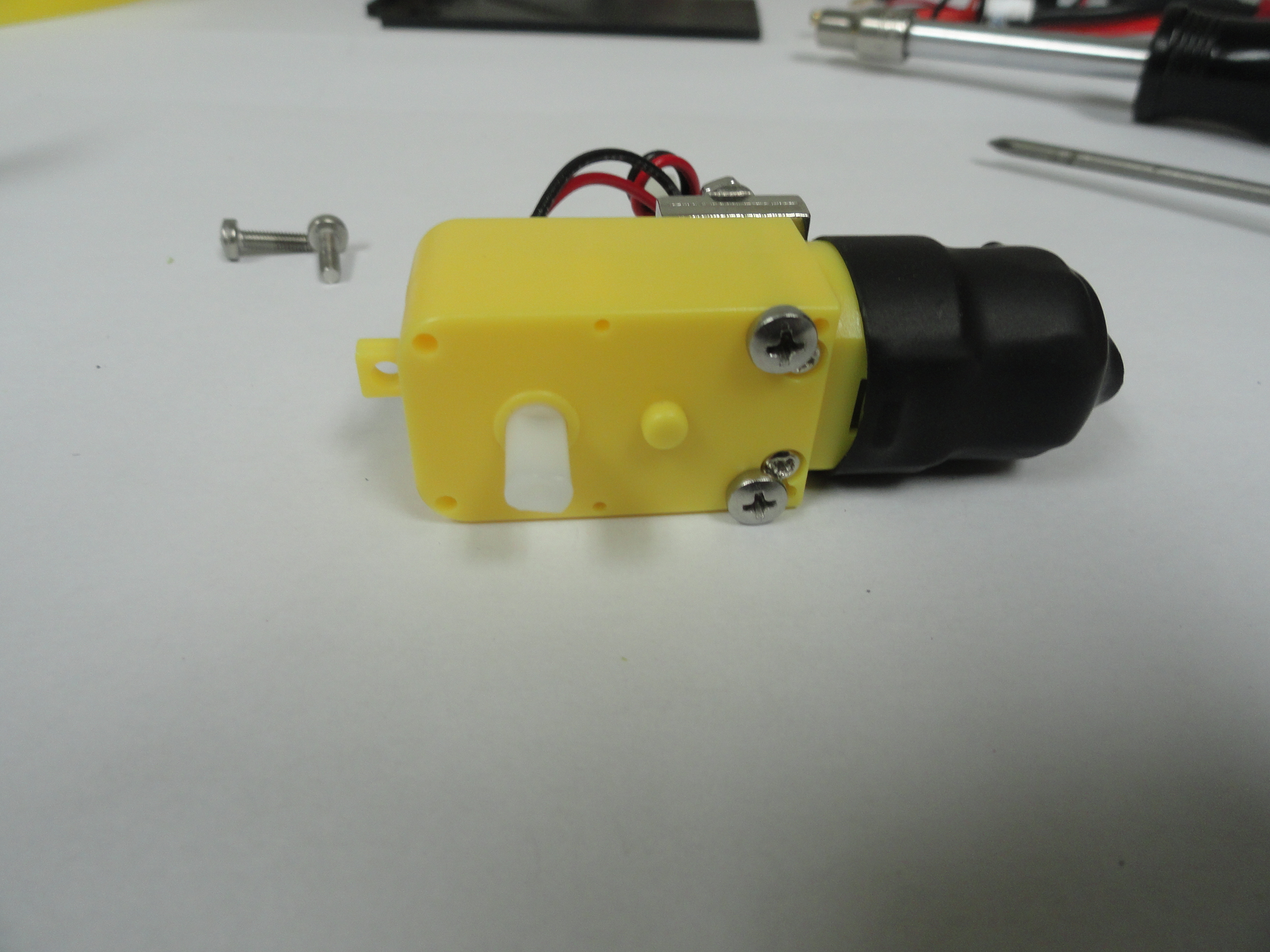
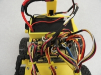
2) Install the motors. The wires go on the inside and the motors are situated so the wheels are in the center of the wheel well. A metal bracket holds the motor down using 2 30mm long screws through the brackets and then 2 10mm long screws with nuts to hold them down to the chassis as shown. Be sure to mount them so the wires are facing inwards. Two of the motors will have the bracket facing one way, 2 the other because of the left/right orientation. Push the bracket against the wires as far as needed for the long screws to go in. The shrink tubing will protect the wires. Do not put the wheels and tires on just yet.
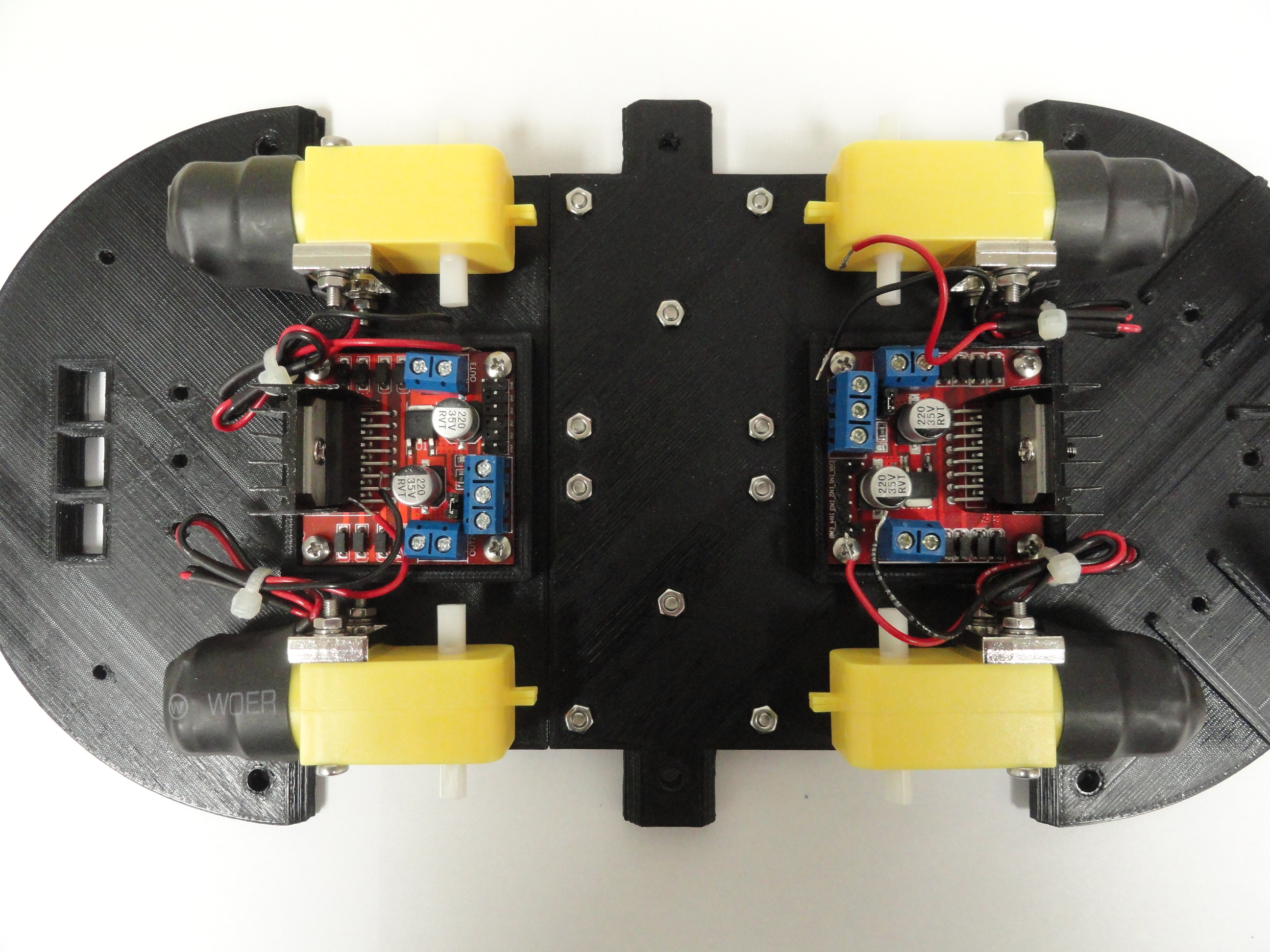
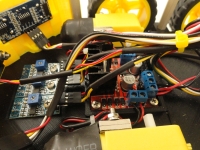
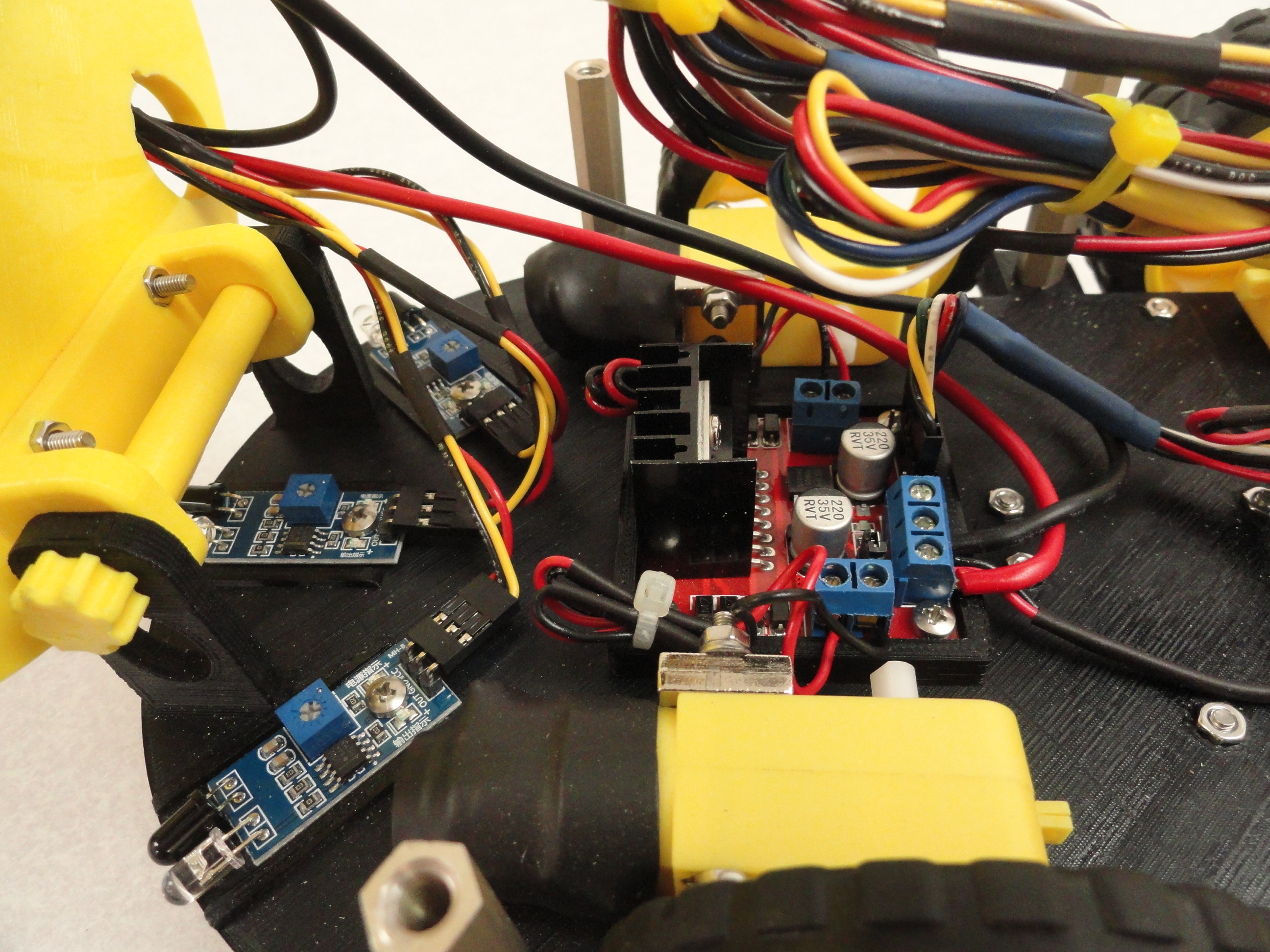
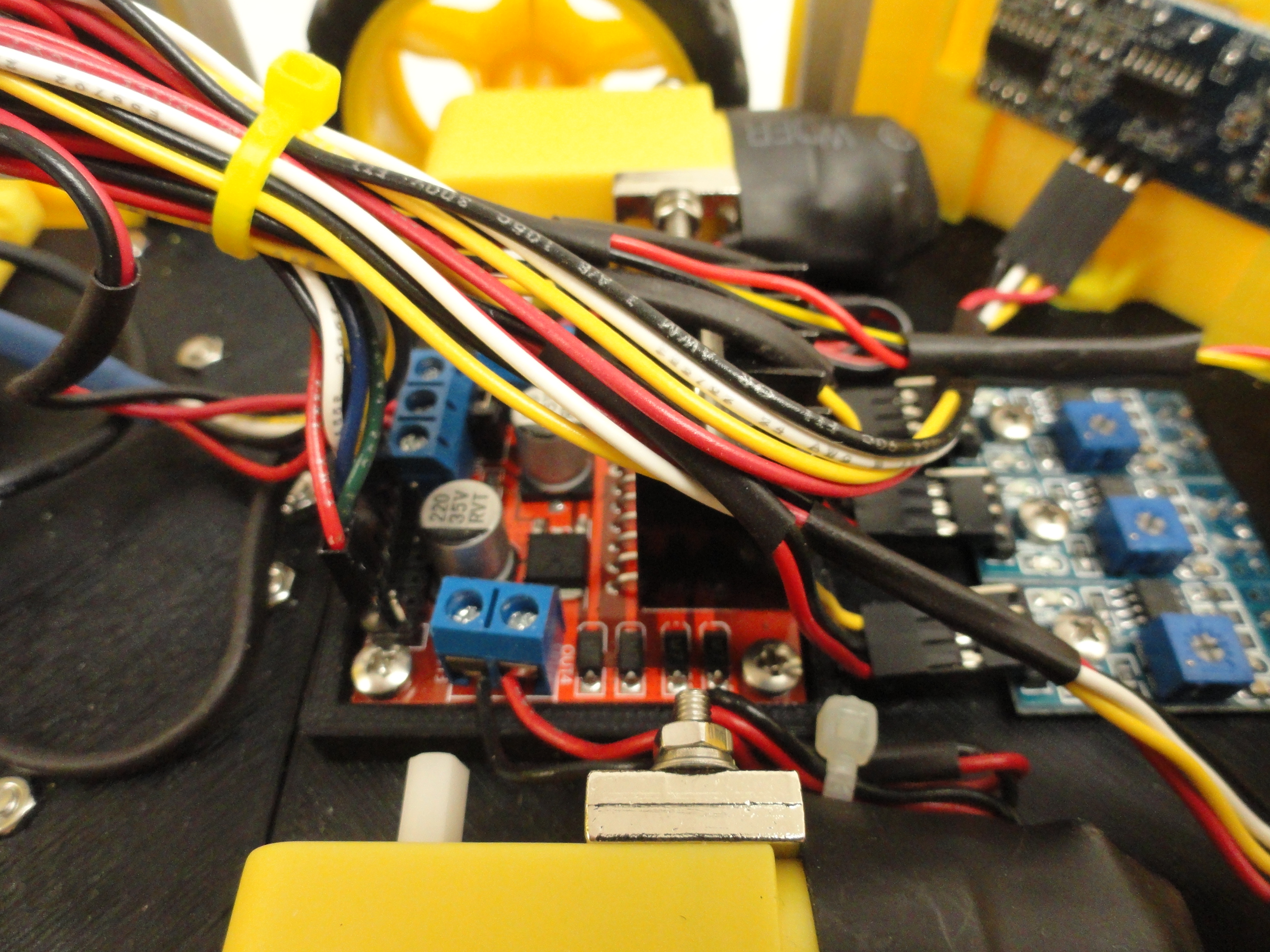
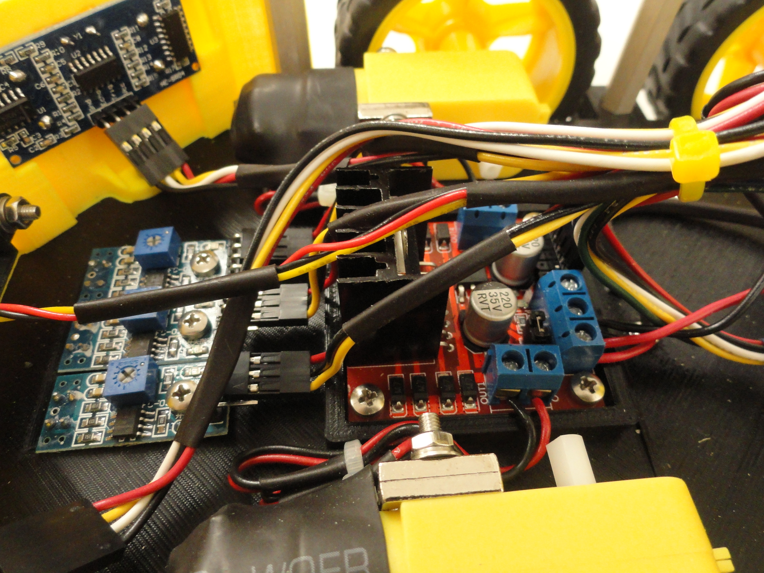
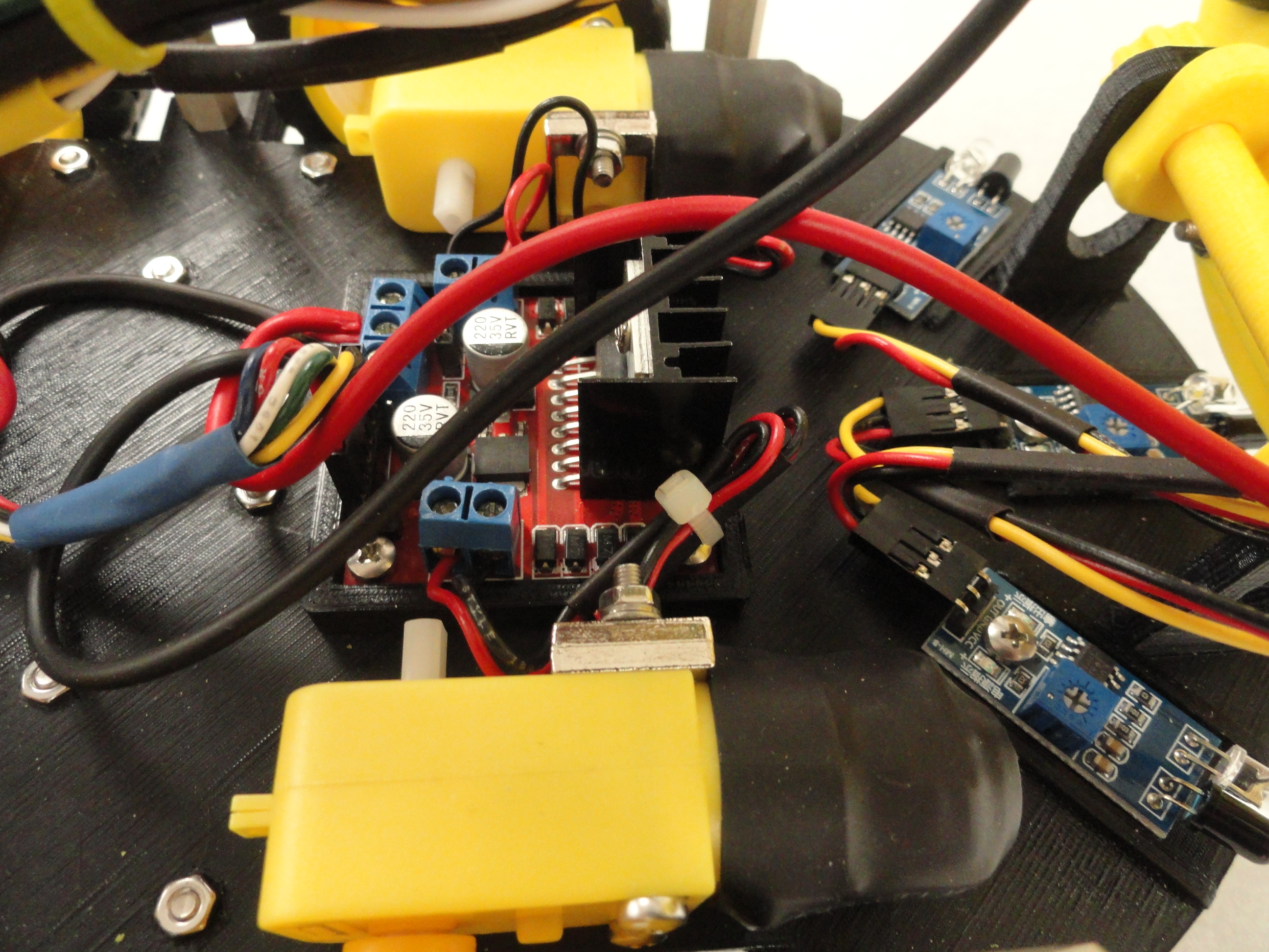
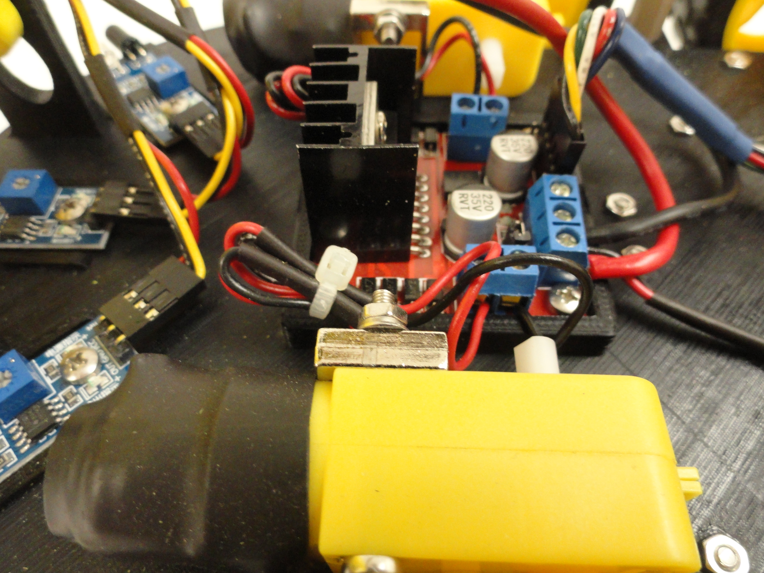
3) Install the 2 Dual H Bridge DC Motor Drive Controller Boards. We will refer to them as just 'Motor Controllers' from now on. The cavities for them are made so the board only goes in one way due to the pin interference close to the holes. Tighten them down using the provided 4 12mm screws and nuts. Tighten the 4 nuts enough so they go inside the capture area of the chassis but do not over-tighten. Do the same with the other controller. There are two wiring harnesses that come with these controllers. One has a Yellow band around it, the other a Blue band. The Yellow band is for the Front Motor Controller, the Blue for the Rear. No need to connect them yet.
4) Push the keyed Wheels/Tires on the motors. Watch how they are keyed and they slide on for a snug fit. With the Wheels on the motors, ensure the wheels are perfectly straight in the wheel wells. If they are pointing slightly off, loosen the chassis motor mounting screws and adjust, then re-tighten.
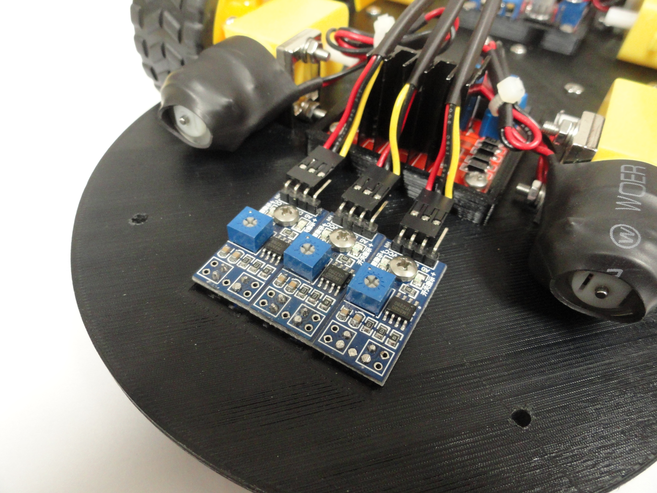
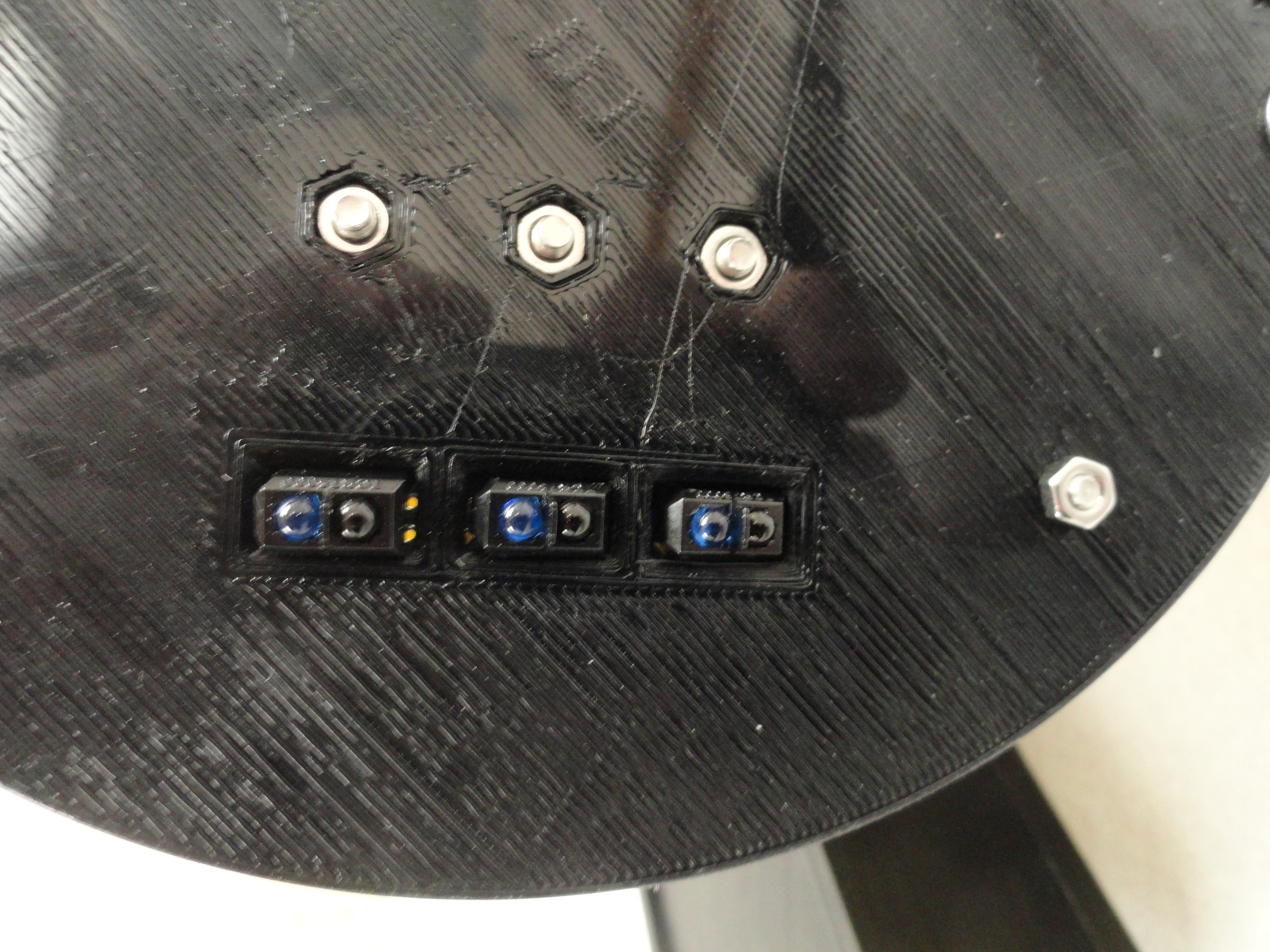
5) Install the front IR Tracking sensors. These are the three sensors with the IR LED's facing downwards. They go in so that the IR LED's go down into their respective holes in the bottom of the chassis. Use the 3 10mm nuts and bolts to secure. With these three sensors there is three wiring harnesses. Plug one end of each harness into the sensors observing proper orientation and leave the other end loose for now. The A0 connection at the sensor is not used. Be sure to use the DC Electricians Rule #1 when installing wiring. These wires are long because they need to stretch to the front of the car even when the hinged top is open.
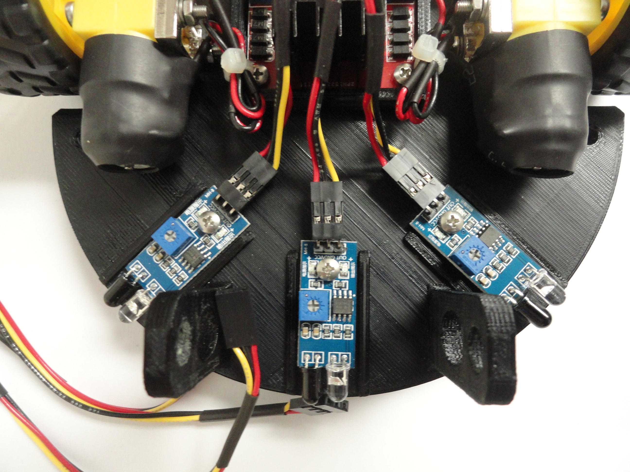
6) Install the rear facing IR sensors. These are the three sensors with the IR LED's facing outwards. Each one provides collision avoidance in
a different zone in the rear of the car. Use the provided 3 10mm nuts and screws to secure. Have the harnesses close by but perform the next step before
plugging them in. Do not try to tie the wires down yet because they are routed in a special way.
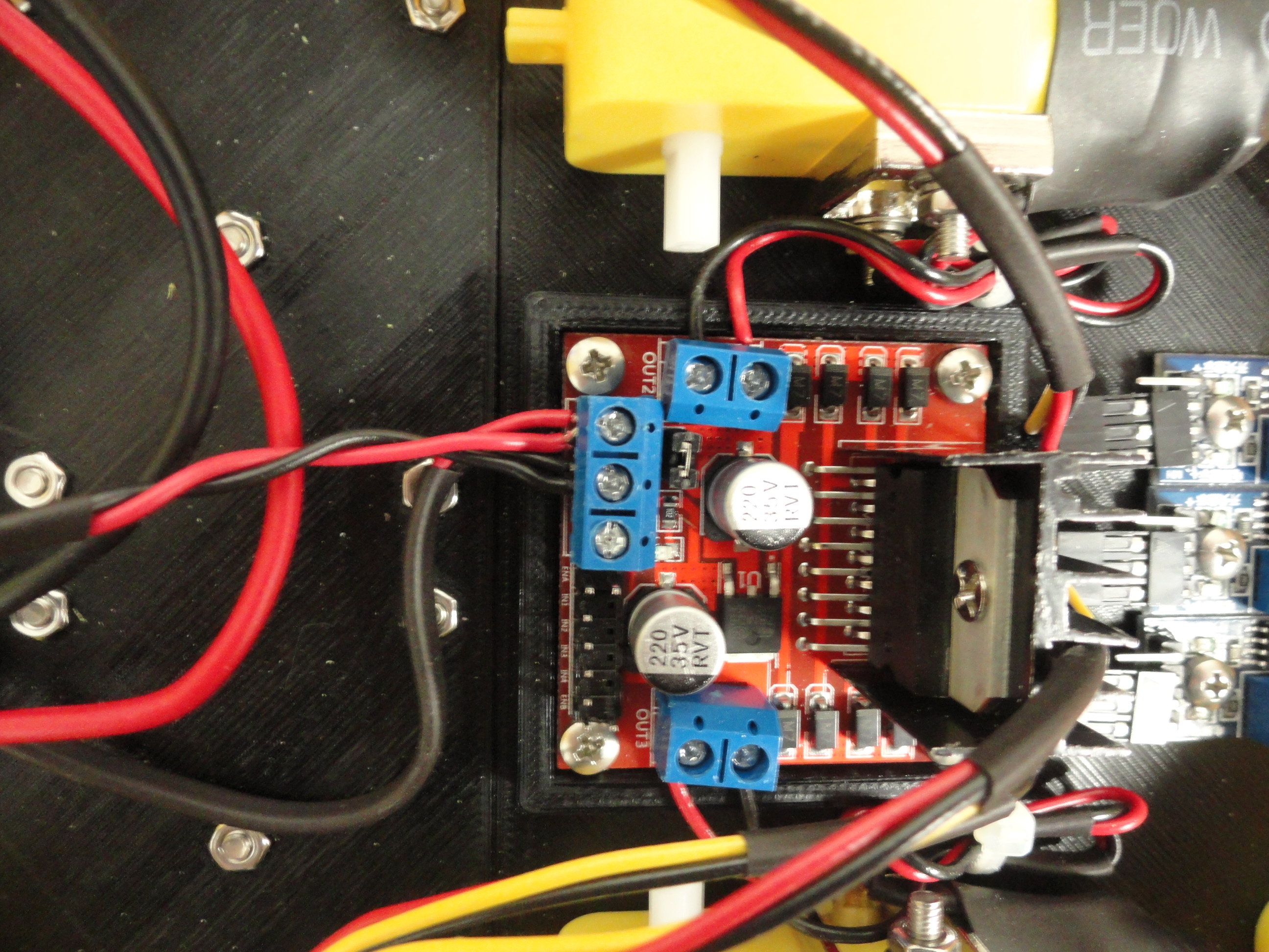
To finish up the Motor Controllers, hook up each motor to the Motor Controllers. Since it is DC, the penalty for hooking up these motors backwards
is, they run backwards! That can be fixed in the software, but let's do this right. The terminals on the controllers that are facing the motors are the
ones we will use to connect them. Do not over-tighten those terminal screws! They just need to be snug.
Front Motor Controller:
Drivers Side (left) - Black is in the front then Red behind it.
Passenger Side (right) - Red is in the front then Black behind it.
Rear Motor Controller:
Drivers Side (left) - Red is in the front then Black behind it.
Passenger Side (right) - Black is in the front, then Red behind it.
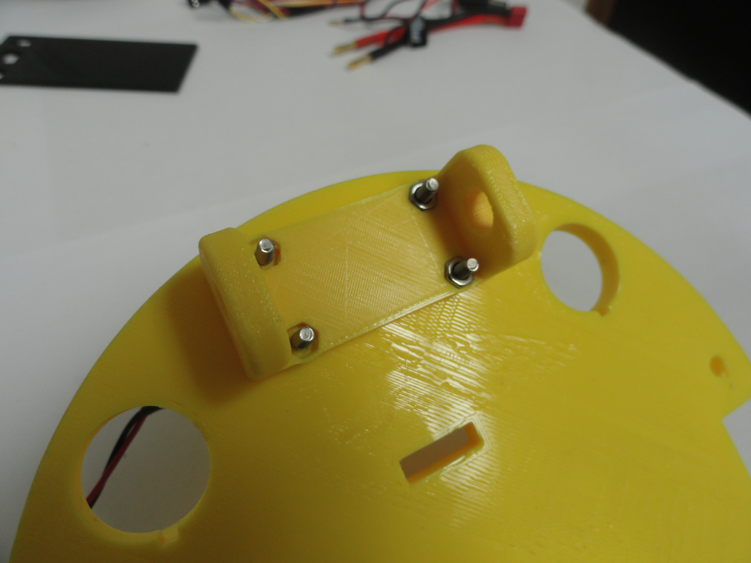
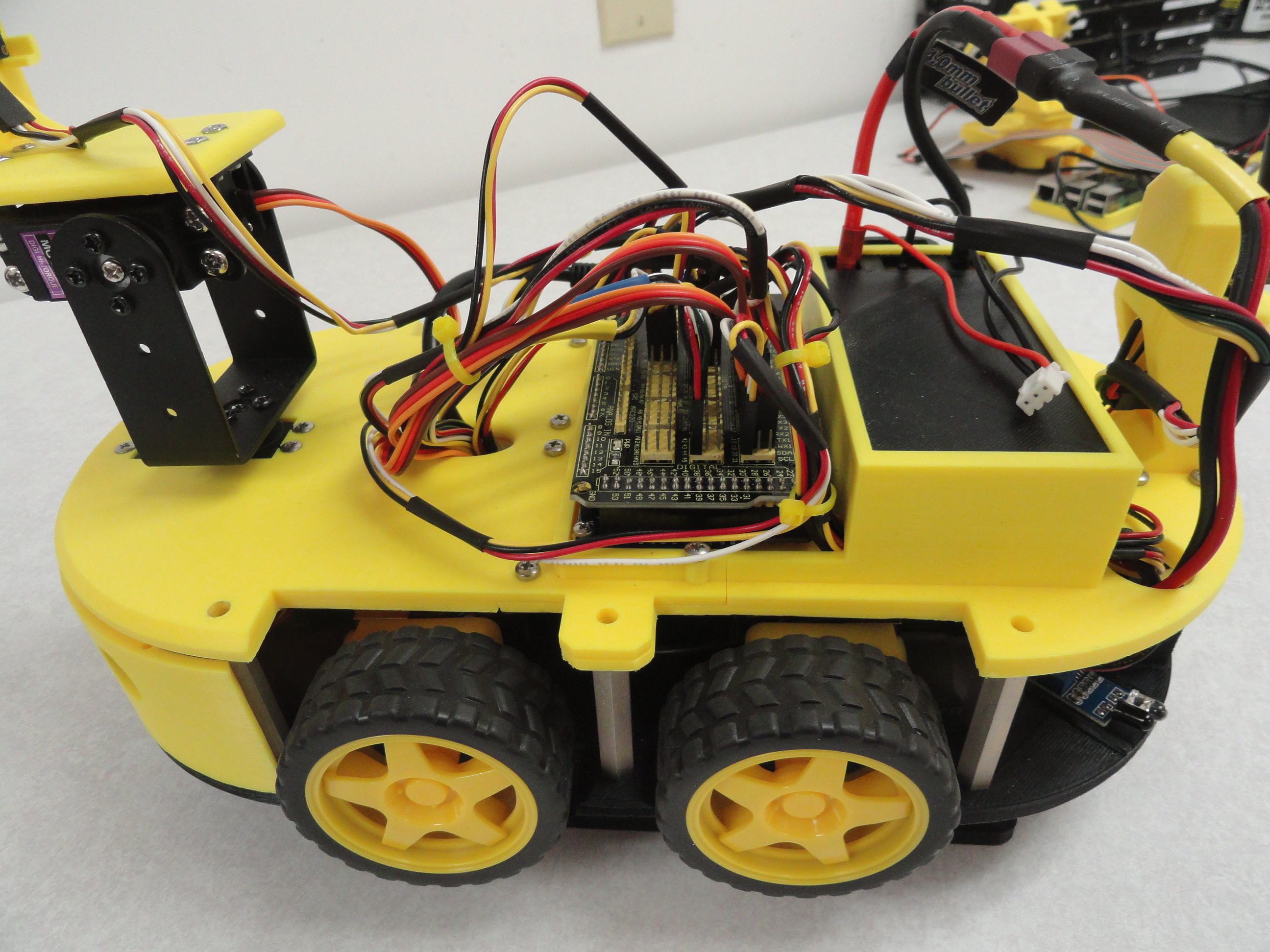
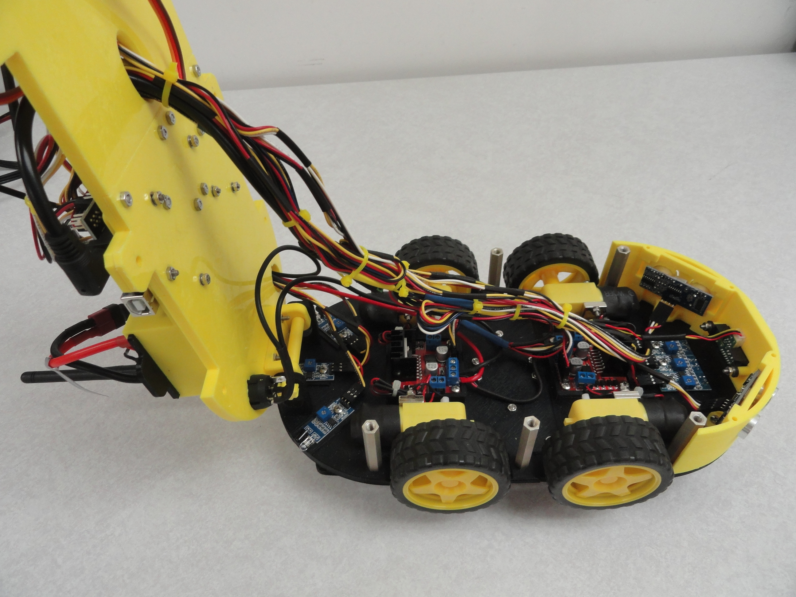
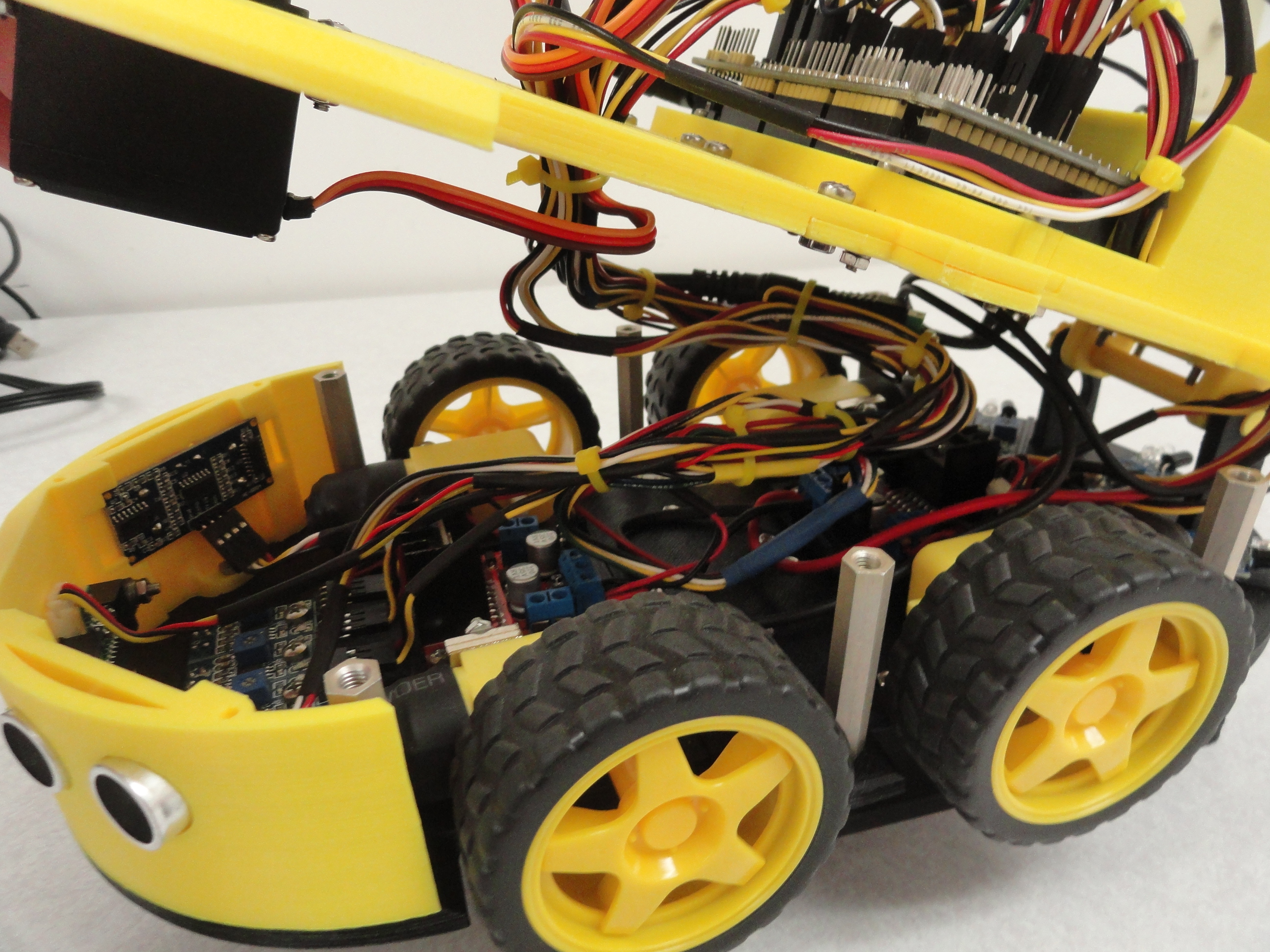
7) With the top chassis pieces bolted together properly, install the hinge frame on the underside of the top chassis assembly. Use the provided 4 16mm screws and nuts in their capture configuration. Install the two chassis pieces together at the hinge assembly meshing the two pieces together, then securing with the provided hinge bolt. Notice that one side of the bottom chassis hinge has a threaded hole. Slide the bolt in from the other side, then rotate the bolt to keep it in place.
Install the 6 1.75 Inch/4.5cm Aluminum Standoffs (3 on each side of the car) in the larger bottom chassis holes using the provided Phillips head screws. Only fasten to the bottom of the Car so we can use the Hinge unimpeded for now.
8) Install the wiring harnesses for the bottom rear IR sensors. Install the harnesses as before but this time, route the wires up through the left (drivers side in America) rear hole, through the holes in the battery box to the Arduino Mega Cavity. This is the only route where they are long enough.
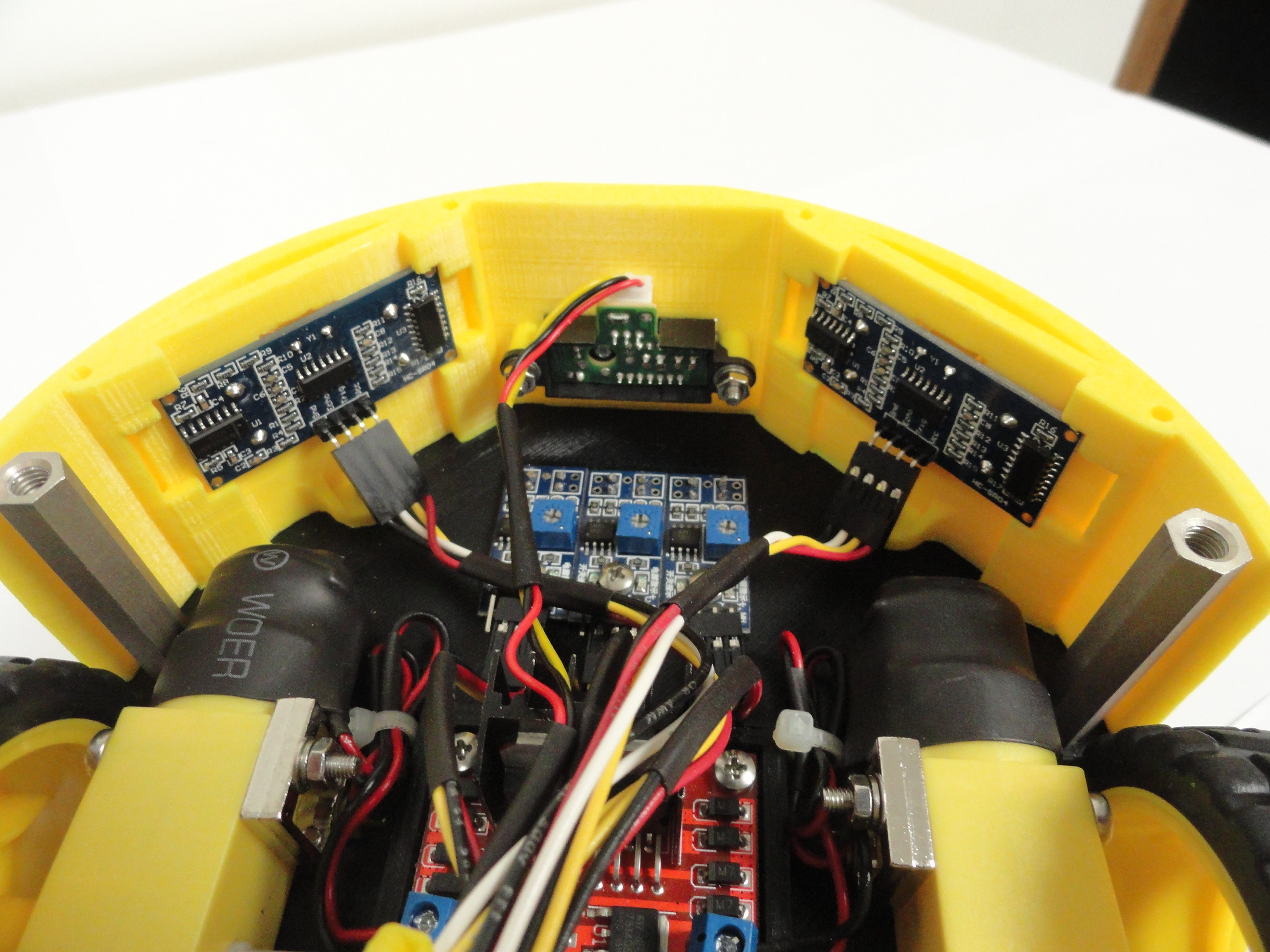
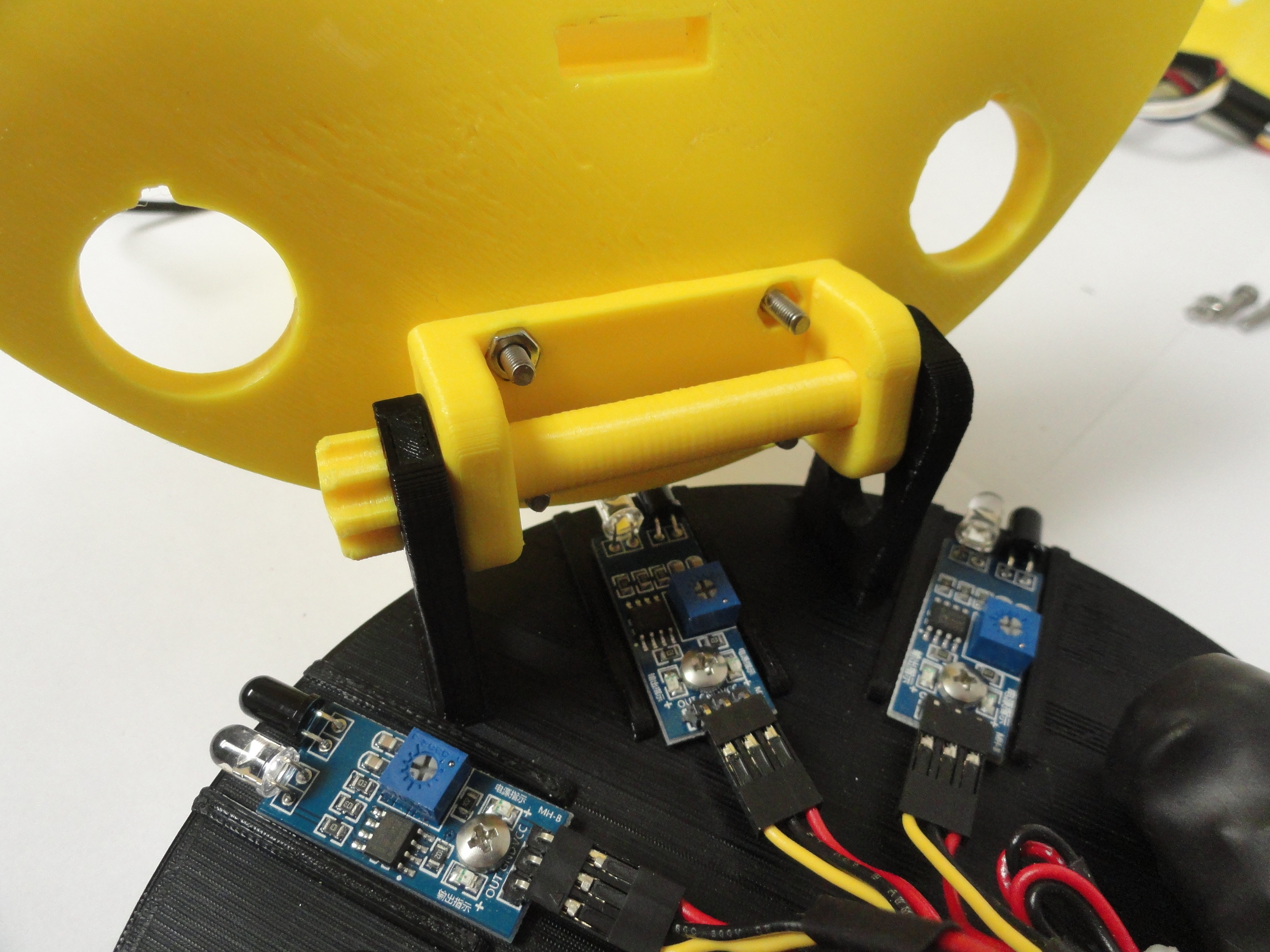
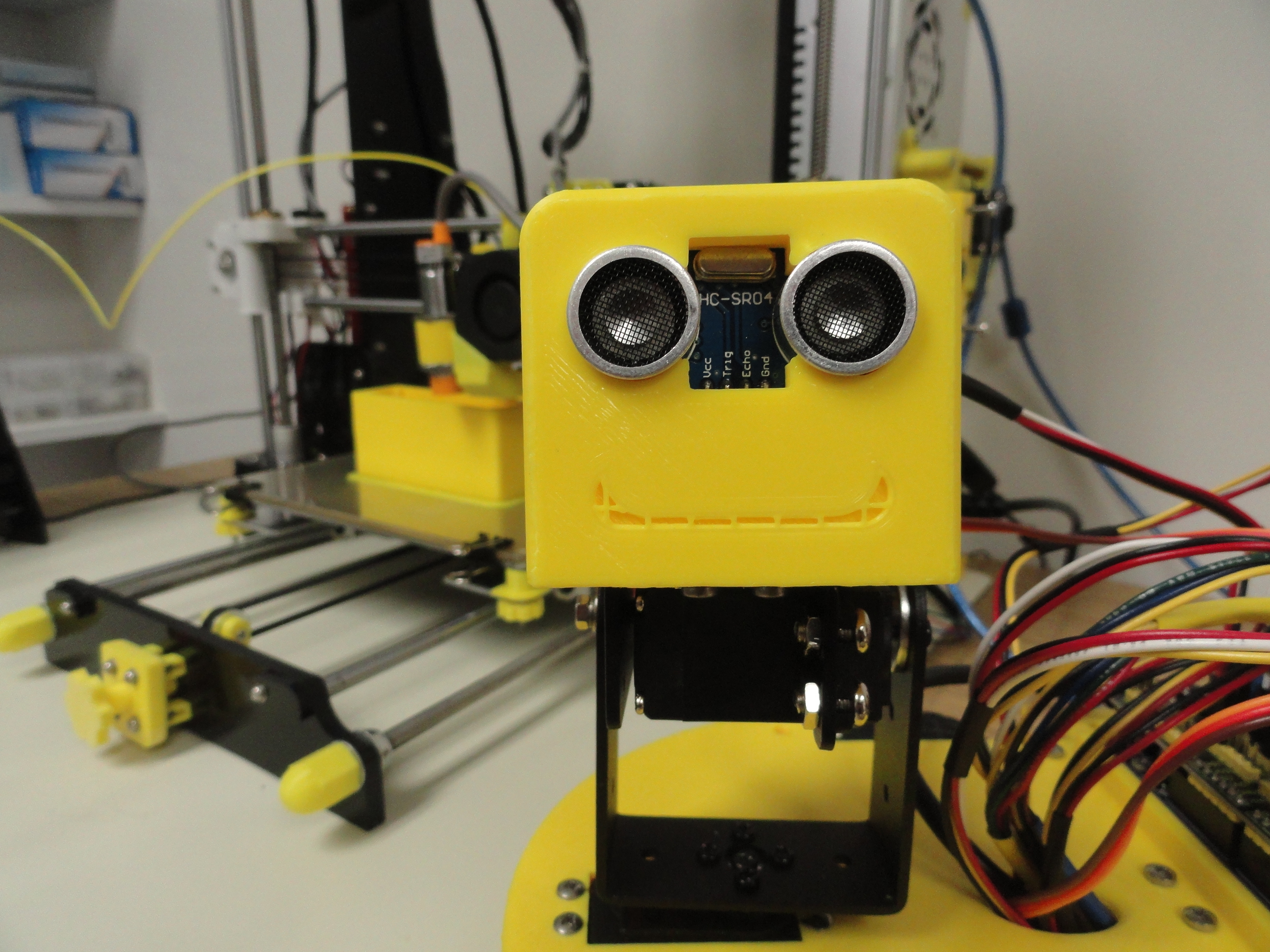
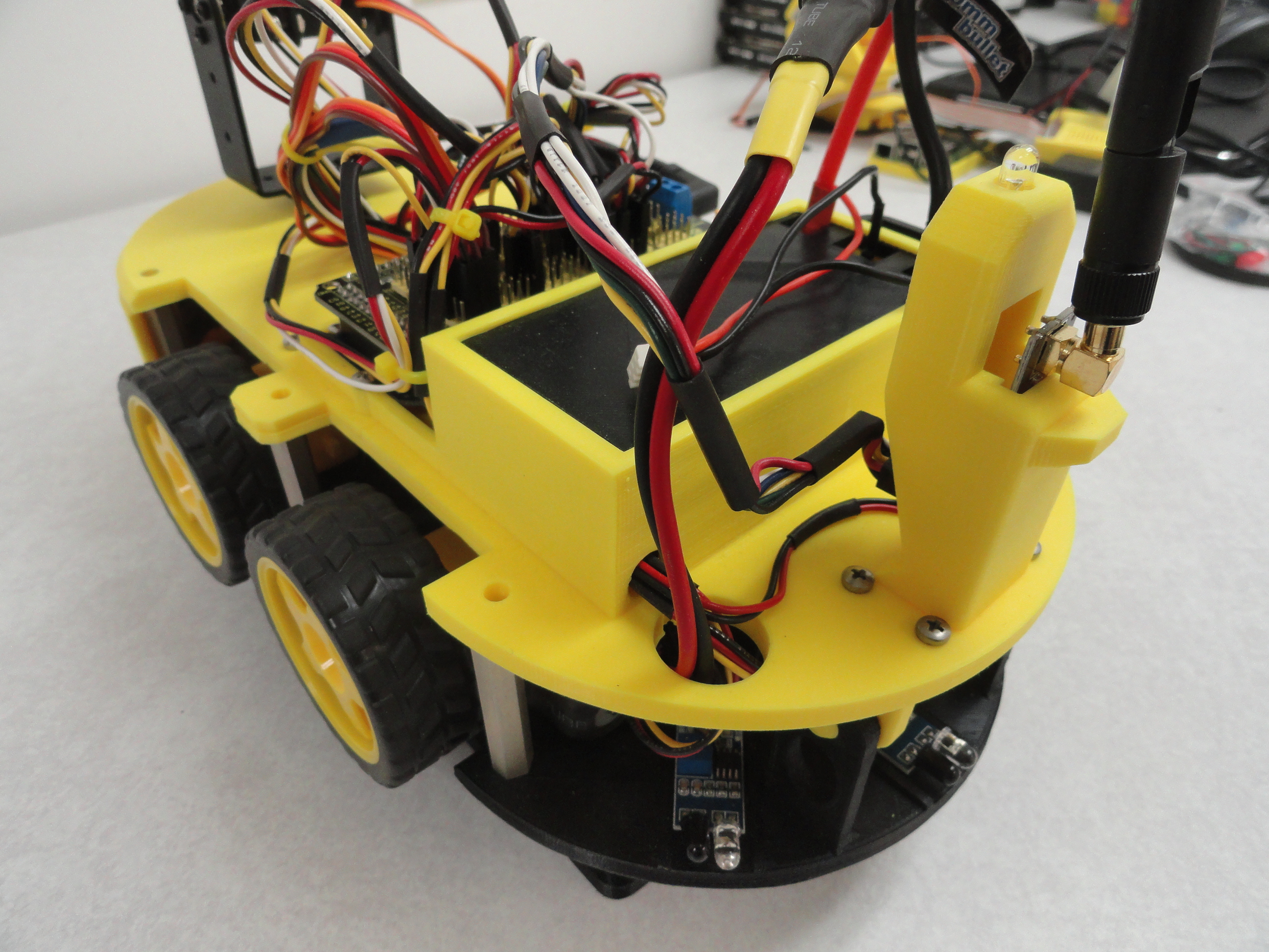
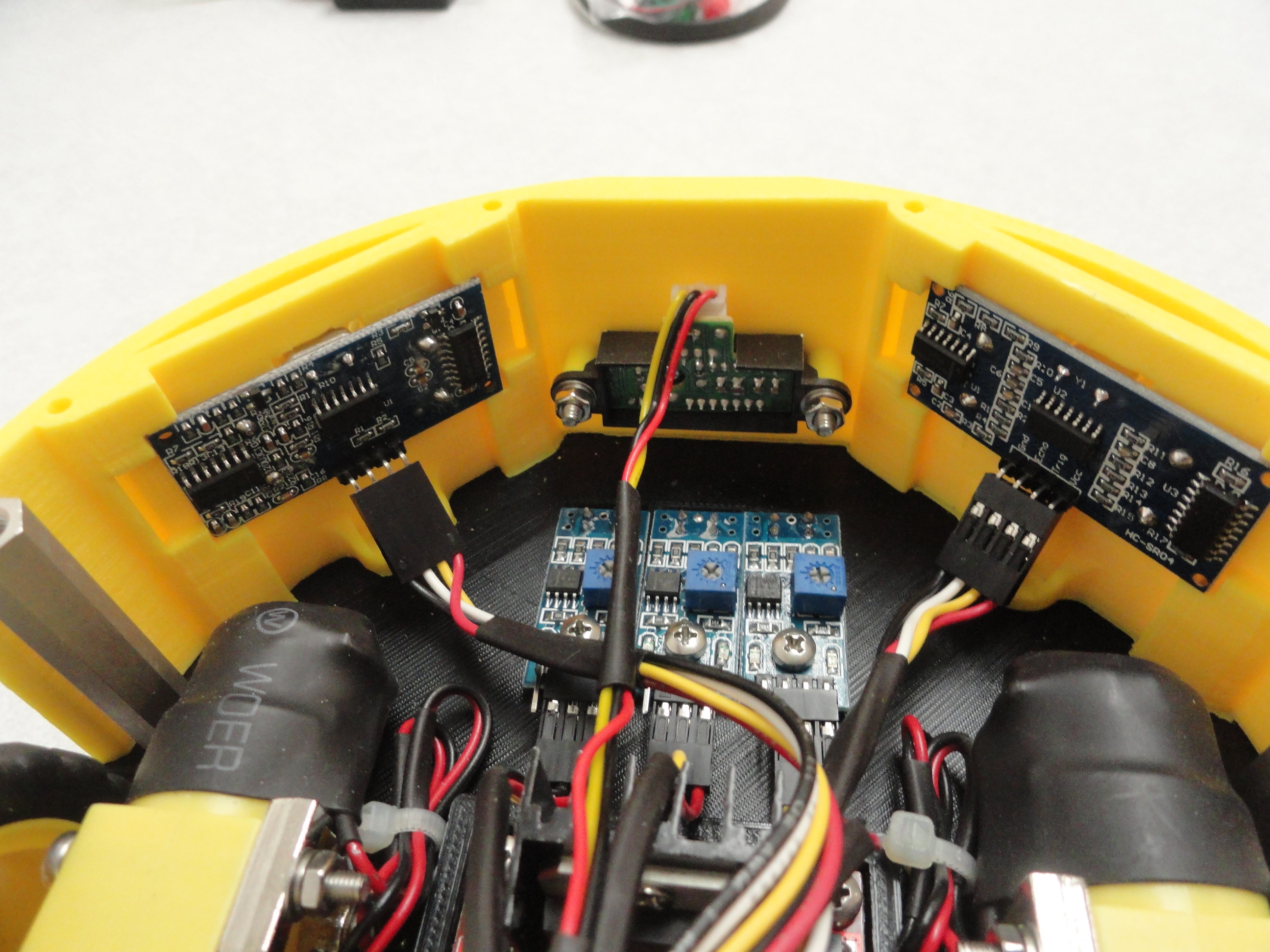
Install the Front Fascia. Install the Sharp IR Forward Proximity Sensor in its slot in the center of the front fascia. With the connector facing up, secure with the 2 20mm screws and nuts that are provided. The 2 16mm screws are with the Fascia that go down into the bottom chassis assembly. Tighten them when you have everything nicely aligned. Once bolted down, snap in the two HC-SR04 Sonar sensors (the sensors that are looking at you!). They snap fully into place without much effort.
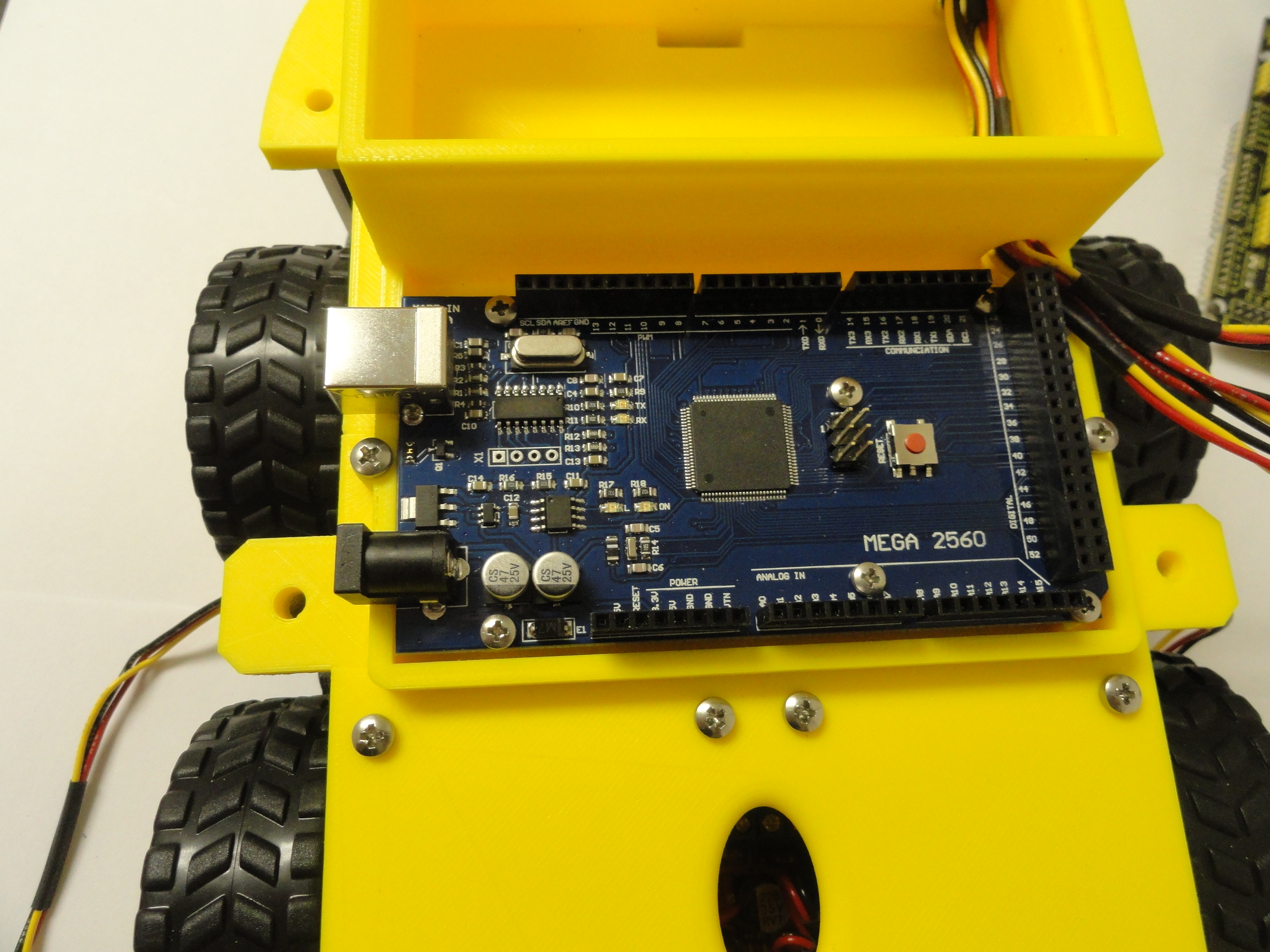
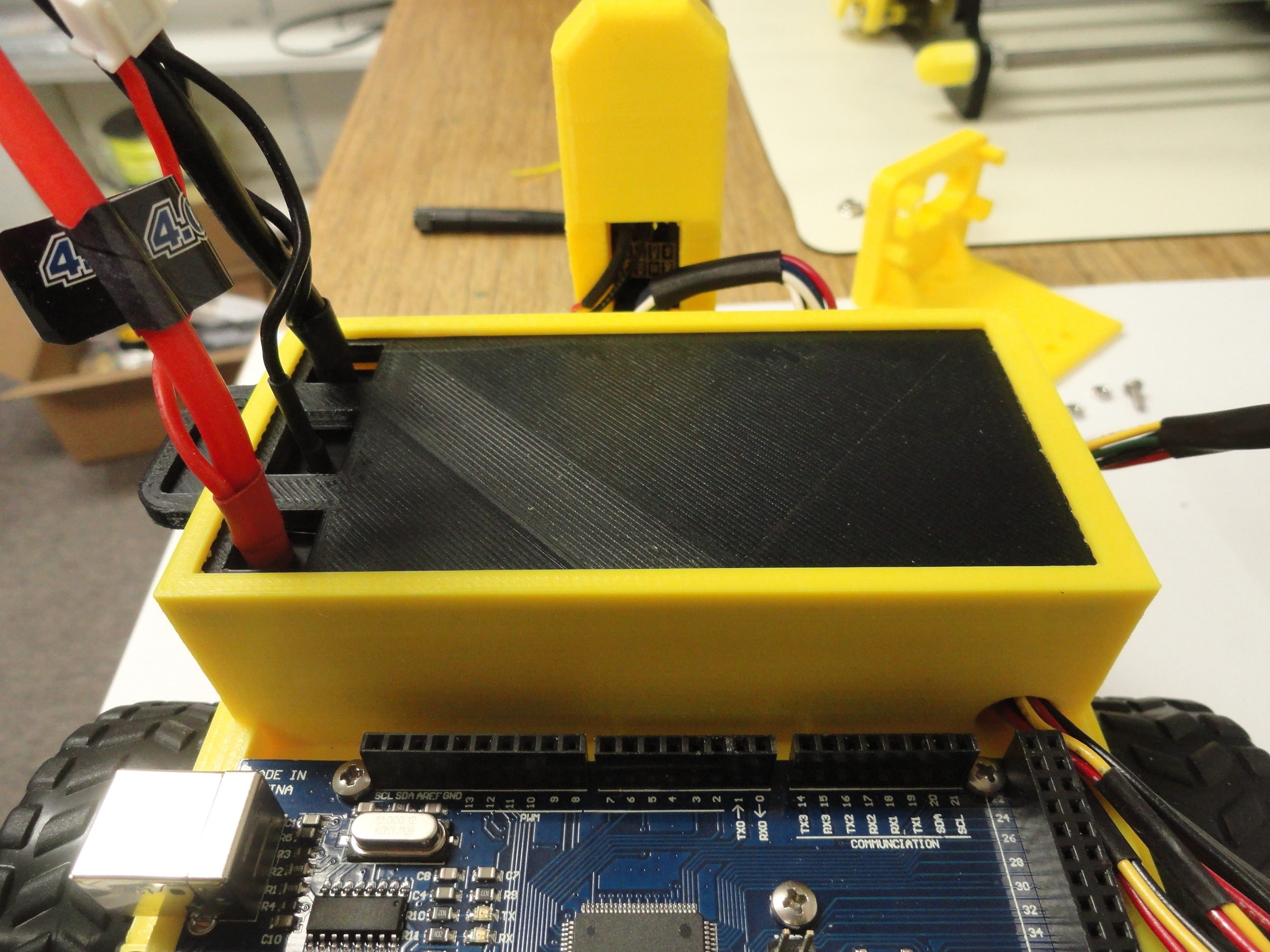
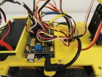
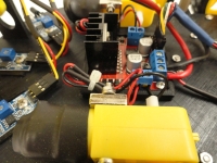
10) Install the Arduino Mega 2560. Do not install the Shield yet. You need to use the 6 provided 2.5m x 20mm screws and nuts to fasten down the micro-controller to the chassis. Install the wires going to the LED through the battery cover holes. Keep in mind once you install the shield the battery cover holes will be harder to access. (not impossible)
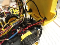
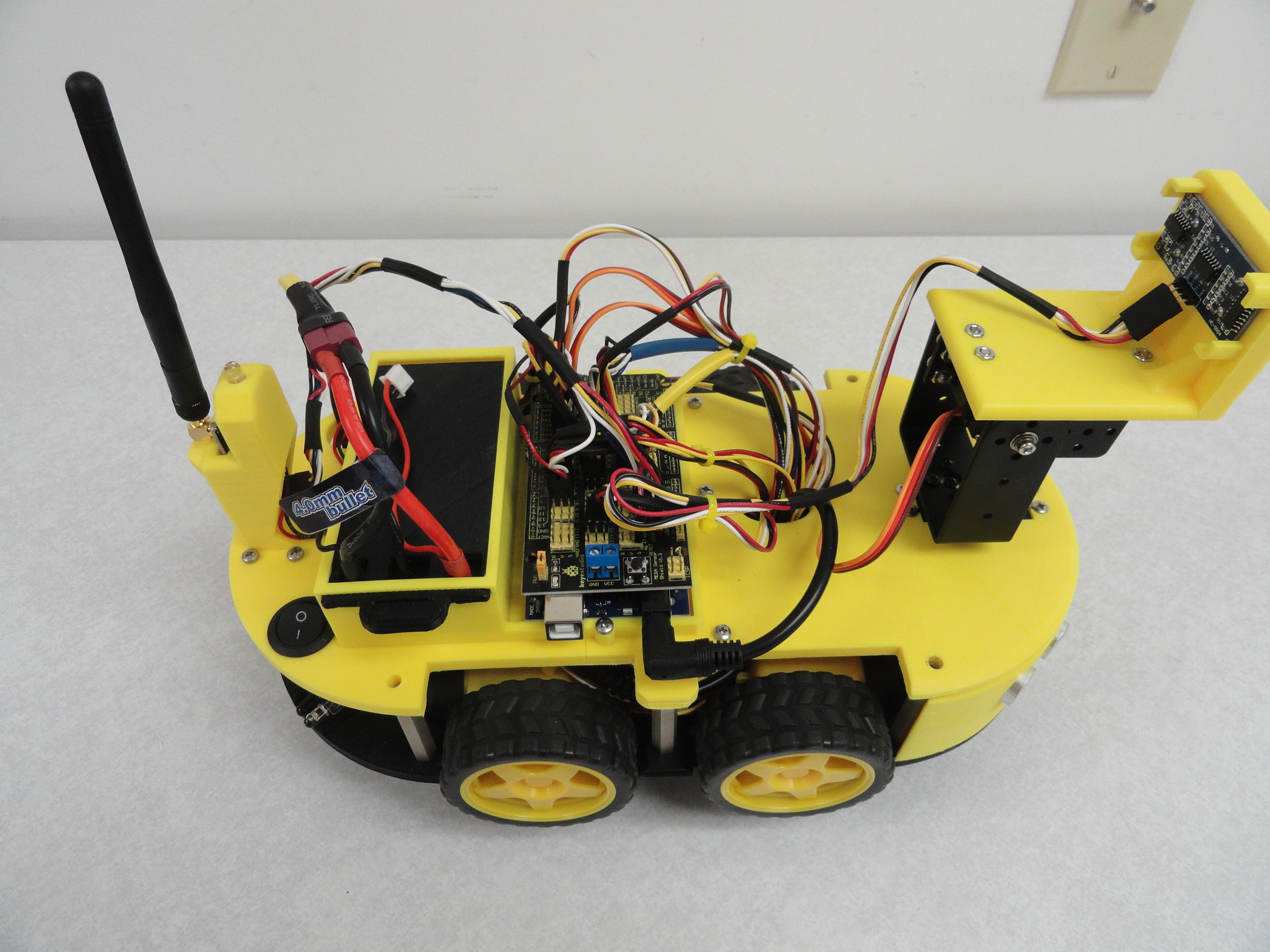
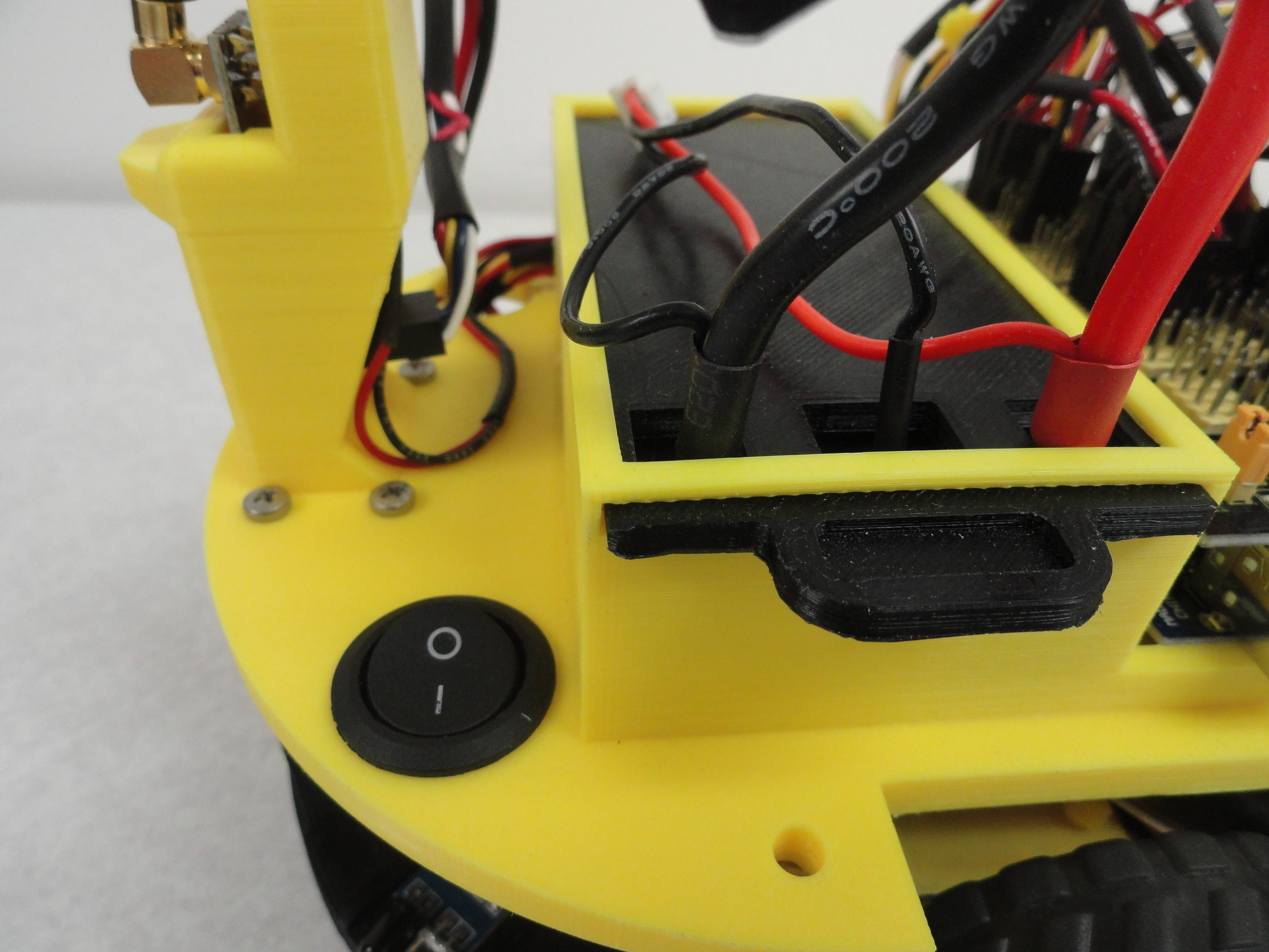
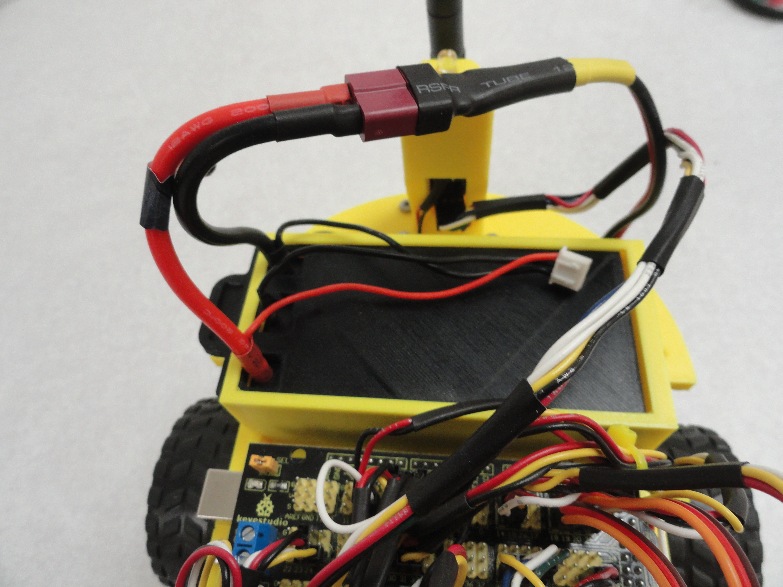
11) Slide the NRF24 Transceiver into the slot in the rear tower so that the antenna connector rests on the rear edge. With the need for doing a lot of opening and closing of the chassis during assembly, no need to install the antenna yet. Connect the harness to the NRF24 so that the red and black wires are pointing towards the left side of the car. Route the cable over the Battery Box directly to the Arduino. Instructions on how to hook it up are forthcoming.
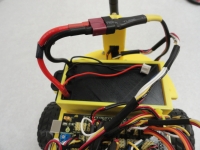
12) Install the battery so that the battery poles are facing towards the right side of the car, then slide on the cover. The holes in the cover coincide with the holes in the battery. Connect the Battery cables to the battery by pushing them into the battery. Positive is in the front, Negative in the rear, then there is a charging sense wire in the middle. You will use this to plug in the special charger so it can determine how to balance charge the two cells differently for a full charge.

13) Install the Switch Harness. Put the wires from the harness down into the right side hole first then push the switch into the right side rear hole so that the keeper is oriented forwards. It clicks right in. Route the battery connections back through the left side rear hole and up to connect to the battery, but do NOT connect it yet. The two soldered ends, one Red for Positive and the other Black for Negative or Ground go to the closest (rear) Motor Controller as shown.
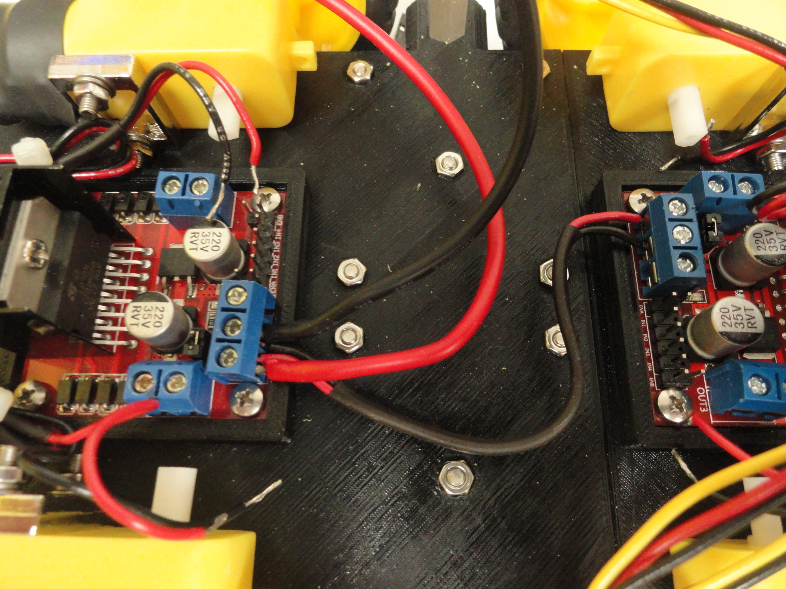
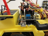
14) Install the two wire short jumper. The short red and black jumper go between the Motor Controllers to provide power to the second Motor Controller as shown. With the two jumper wires connected, you also need to connect the Arduino Power Harness to the forward Motor Controller to the same connections. The 90 degree connection goes to the Arduino.
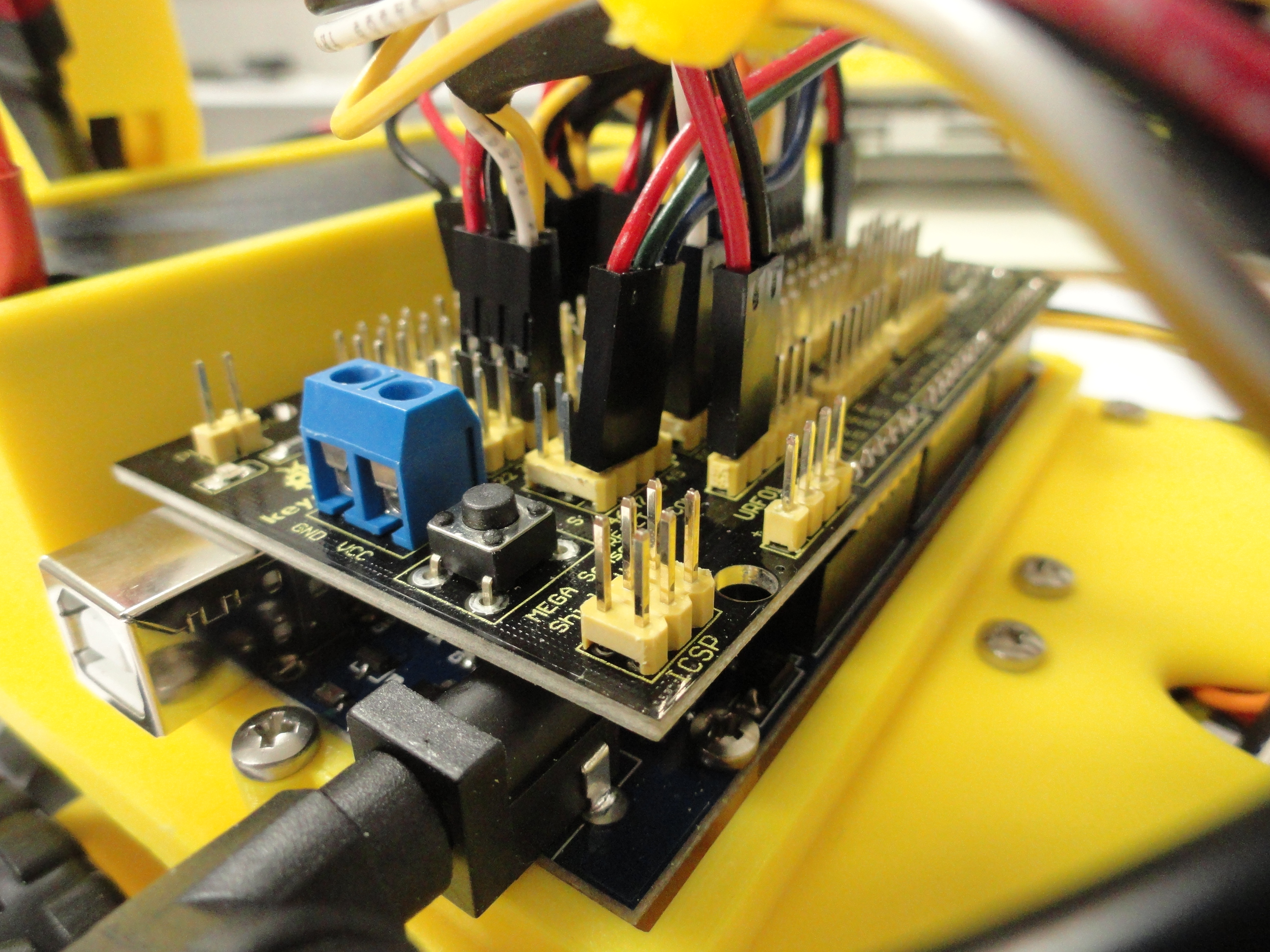
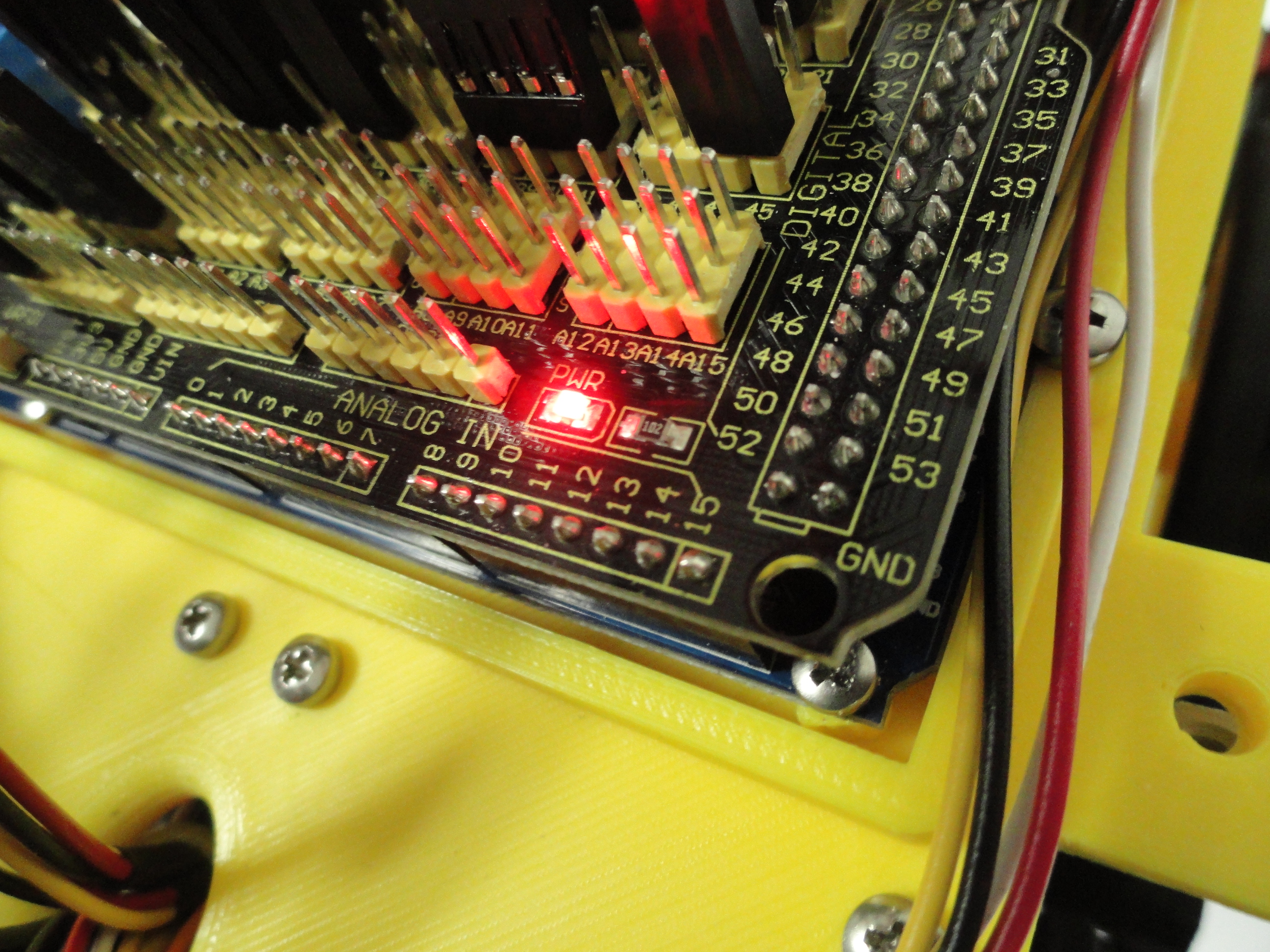
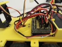
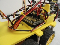
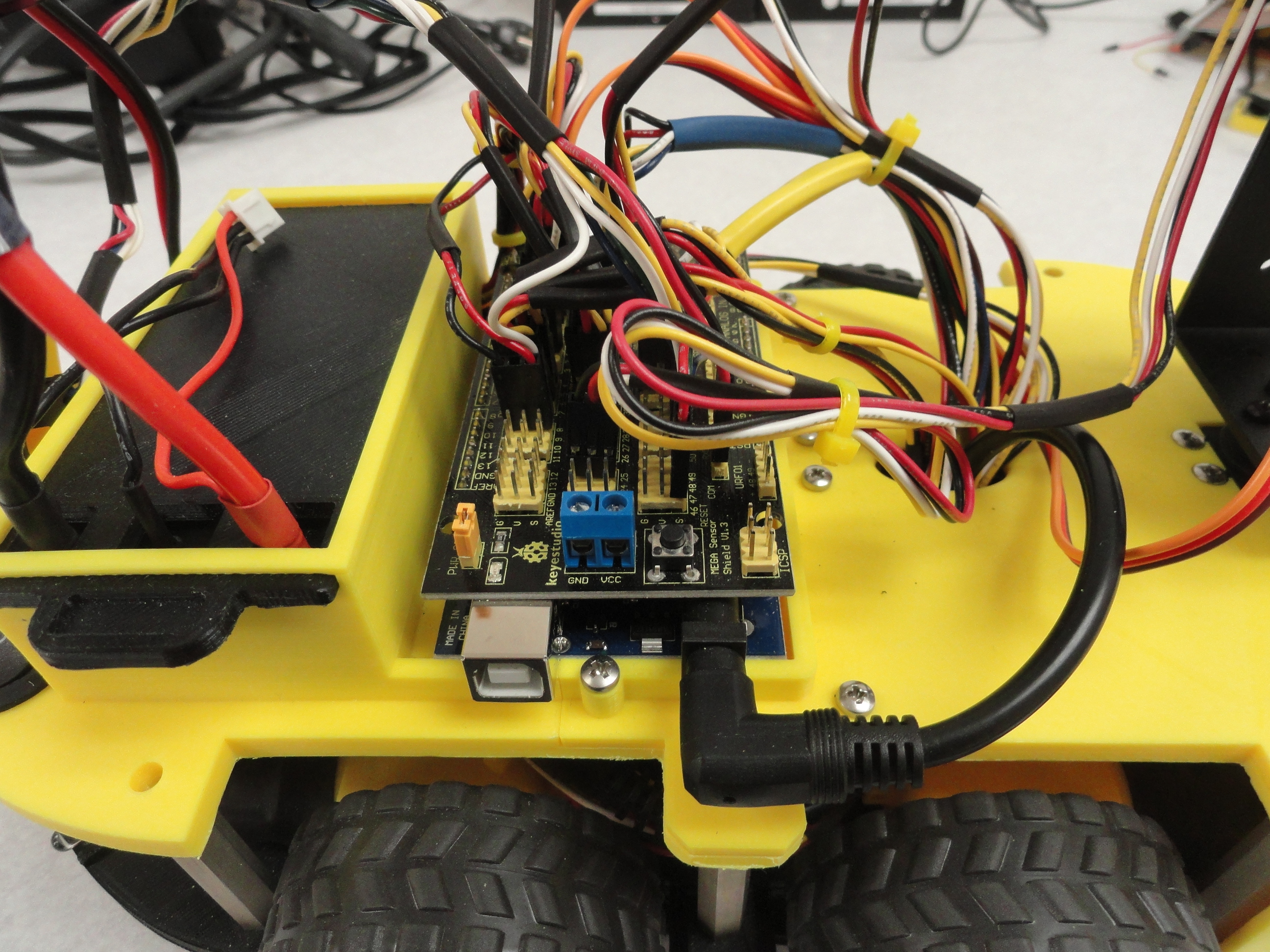
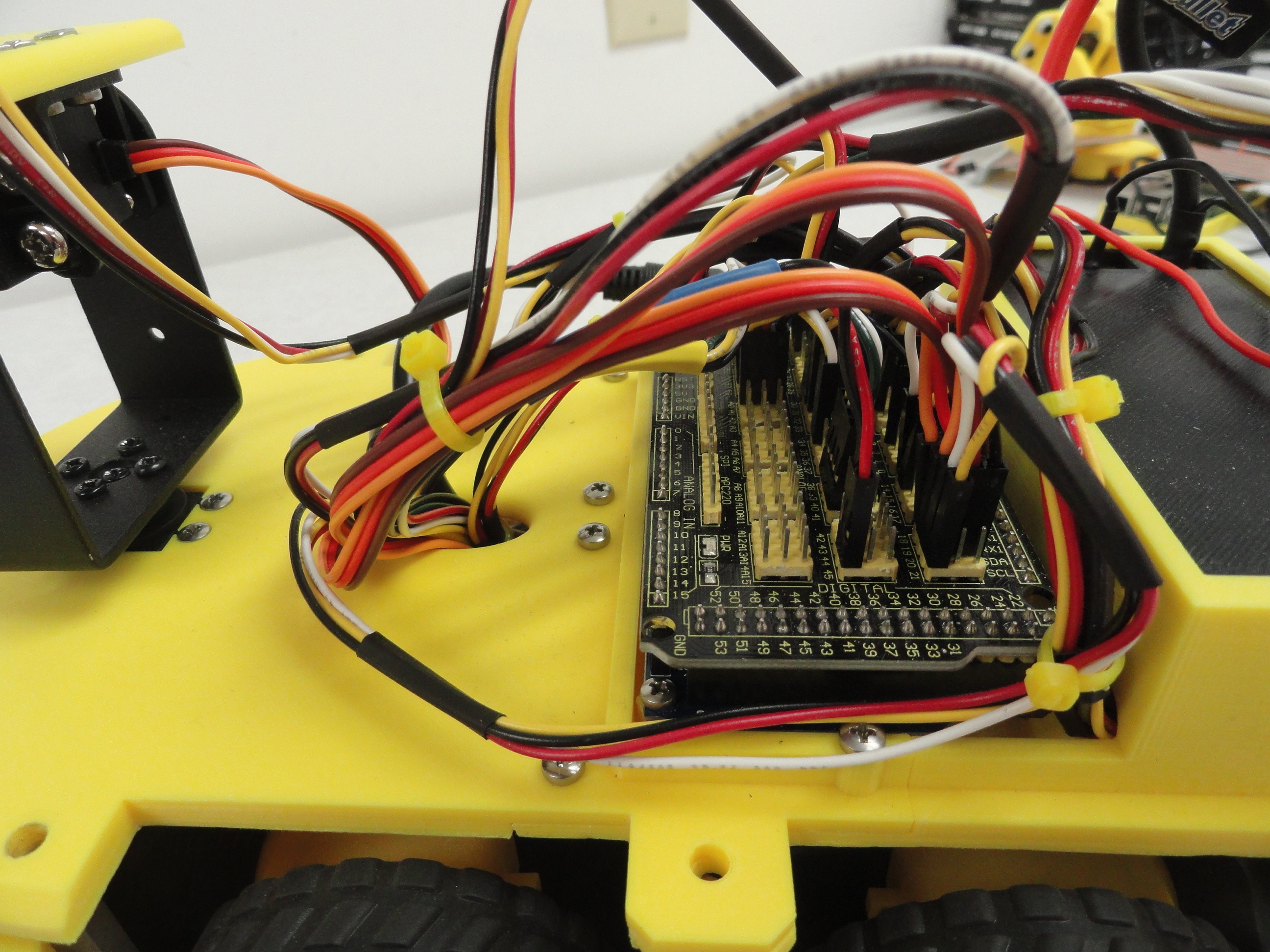
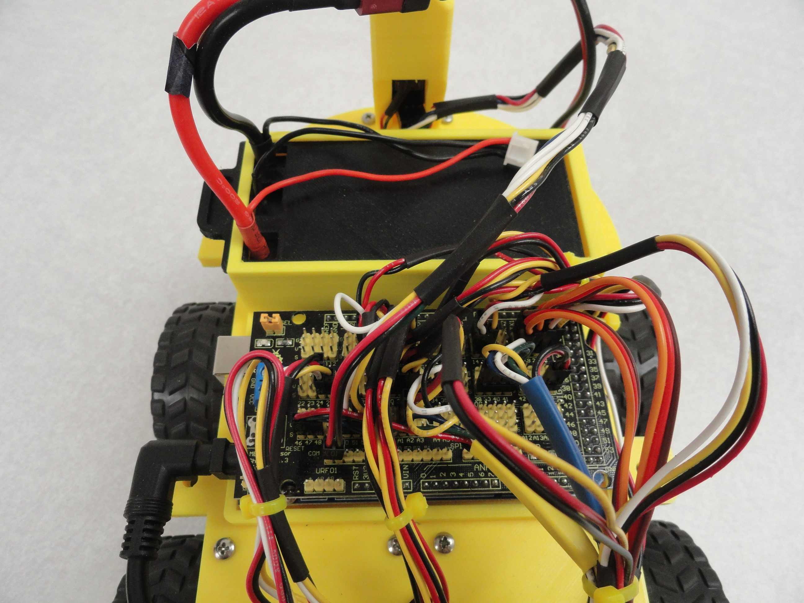
15) Install the Arduino Sensor Shield. VERY carefully ensure all of the pins are properly aligned and push the sensor shield all the way into the Mega. Use a small flashlight to ensure all of the pins are properly seated. There are several different Mega 2560 Sensor Shields but they all work relatively the same. The Arduino Mega 2560 has 53 Digital Pins and 15 Analog Pins along with various Power Pins for 3 volt, 5 volt and up to 12 volt power input.
It is very important that we do not connect our power incorrectly or we will have an instant puff of smoke and something will be damaged. If you have a shield that has a power jumper on it named PWR SEL in the upper left corner, those pins need to be jumpered together. Be VERY sure your wiring is correct before doing that. Jumpering means voltage will now be available at the desired pins. If you try this and all of the sudden the lights on everything go out, it's because you have something wired incorrectly. Remove it immediately! Red wires always denote +5 volts and black wires always denote ground. The kit comes with the required jumper but purposely left off until you have thoroughly checked your wiring.

This is the Sensor Shield's Drawing. Each Pin on the Arduino Mega is represented on this Shield. Along with each numbered pin is a Power and a Ground Pin. This is mainly for convenience because all of the power and ground pins are tied to the 5 volt line. While this works for most of our project, there is one exception and that is the NRF24 Radio. For that, we need to power it with 3 volts. It is not acceptable to power it with 5 volts so we need to find the 3 volt pins. They are not always marked. Look for a COM line of pins or Bluetooth line of pins and with a Multimeter locate the positive 3 volt pin. On the Keyes MEGA Sensor Shield V1.3, we use the two pins that are directly above the URF01 markings or the first two pins on the COM line of 6. For everything else, we use the standard 5 volt power that is above the numbered Digital Pins.
Each Sensor requires power, ground and sense wires in the least. The three HCSR-04 Sonar "Bug Eyes" need an additional sense wire.
The entire Super SmartCar is wired as follows:
- LED goes to Pin 9 and its associated Ground. We will get our power from the Digital Pin itself. Route this wire from the base of the tower through the battery box holes to the Arduino.
-
Motor MOSFET FRONT (Yellow Band) has ENABLE A [black], ENABLE B[red] and Outputs IN1[yellow], IN2[white], IN3[green] and IN4[blue].
This harness is connected to the front motor controller black to the left (drivers) and red to the right. These wires go to the
following on the Shield:
- Enable A [black] to Shield Pin 2 (PWM)
- IN1 [yellow] to Shield Pin 34
- IN2 [white] to Shield Pin 35
- Enable B [red] to Shield Pin 46 (PWM)
- IN3 [green] to Shield Pin 47
- IN4 [blue] to Shield Pin 48
-
Motor Controller REAR (Blue Band) has ENABLE A/C [black], ENABLE B/D [red] and Outputs IN1/5 [yellow], IN2/6 [white],
IN3/7 [green] and IN4/8 [blue]. This harness is connected to the rear Motor Controller red to the left (drivers)
and black to the right (opposite of above). These wires go to the following on the Shield:
- Enable A/C [black] to Shield Pin 44 (PWM)
- IN1/5 [yellow] to Shield Pin 38
- IN2/6 [white] to Shield Pin 39
- Enable B/D [red] to Shield Pin 45 (PWM)
- IN3/7 [blue] to Shield Pin 40
- IN4/8 [green] to Shield Pin 41
(all are in close proximity of each other)
Lastly, make sure the positive and negative from each motor is connected as follows:
FRONT CONTROLLER:
OUT1 = Motor Negative and OUT2 = Motor Positive and OUT3 = Motor Negative and OUT4 = Motor Positive
REAR CONTROLLER:
OUT1 = Motor Positive and OUT2 = Motor Negative and OUT3 = Motor Positive and OUT4 = Motor Negative
Front Motor Controller Harness Length: 26 inches/66 cm
Rear Motor Controller Harness Length: 22 Inches/55.9 cm
Front Tracking Sensor Pinouts. This is for the three mounted on the bottom tier in the front. The other two wires
per sensor go to power and ground.
Left Side Sensor: Analog Pin A1
Middle Sensor: Analog Pin A2
Right Sensor: Analog Pin A3
Tracking Sensor Harness Length (all three): 28 Inches/20.3cm
Rear Collision Sensor Pinouts. This is for the three mounted in the bottom tier in the rear. The other two wires per
sensor go to power and ground.
Left Side Sensor: Pin 32
Middle Sensor: Pin 31
Right Side Sensor: Pin 30
Rear Collision Sensor Harness Length: 14 Inches/35.5cm
Front Fascia Sensor Pinouts:
Left HCSR04 Sonar Sensor: Echo Pin 18 (interrupt) and Trigger Pin 19
Middle Sharp Proximity Sensor: Analog Pin A5
Right HSCR04 Sonar Sensor: Echo Pin 20 (interrupt) and Trigger Pin 21
Front Fascia Sensor Harness Length (all three): 28 Inches/71.1cm
Be sure to identify the correct wires for the Middle Sharp sensor. The ground and power are reversed!!
Front Servo System Pinouts: See Gimbal Instructions below!
Top (Tilt) Servo: Shield Pin 12
Bottom (Pan) Servo: Shield Pin 11
HCSR04 Sonar Sensor: Echo Pin 3 (interrupt) and Trigger Pin 4
Front HCSR04 Harness Length: 12 Inches/30.5cm
NRF24 Transceiver Pinouts: Install the connector on the NRF24 carefully with black and red towards the left side of the car.
Red: +3v (first pin on the COM line (+3v Pin on the shield))
Black: GND (any ground will do on the shield)
CE 3 [white] - Shield Pin 8
CSN 4 [yellow] - Shield Pin 53
SCK 5 [green] - Shield Pin 52
MOSI 6 [purple] - Shield Pin 51
MISO 7 [white] - Shield Pin 50
(connector pin #8 is unused (on the radio end))
Radio Harness Length: 10 inches/24.4cm
LED Indicators for Modes of Operation:
Yellow LED - Shield Pin 26 - Used for Line Tracking Mode on/off
Red LED - Shield Pin 29 - Used for Staircase Detection on/off
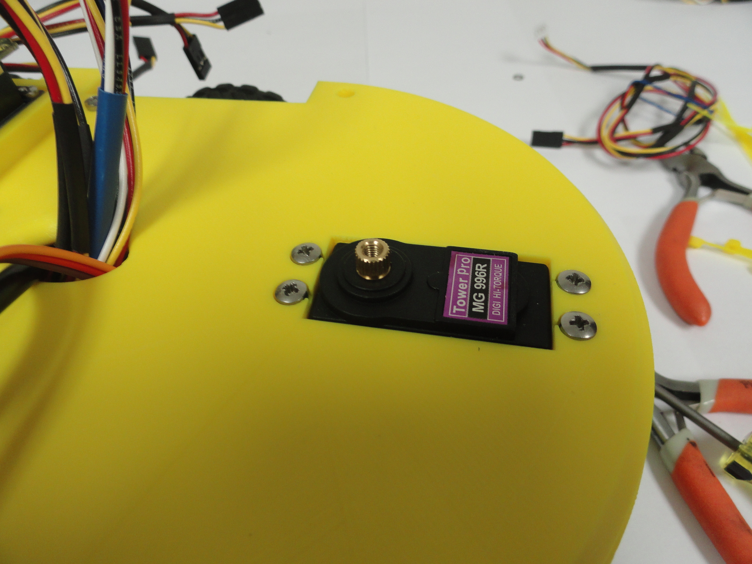

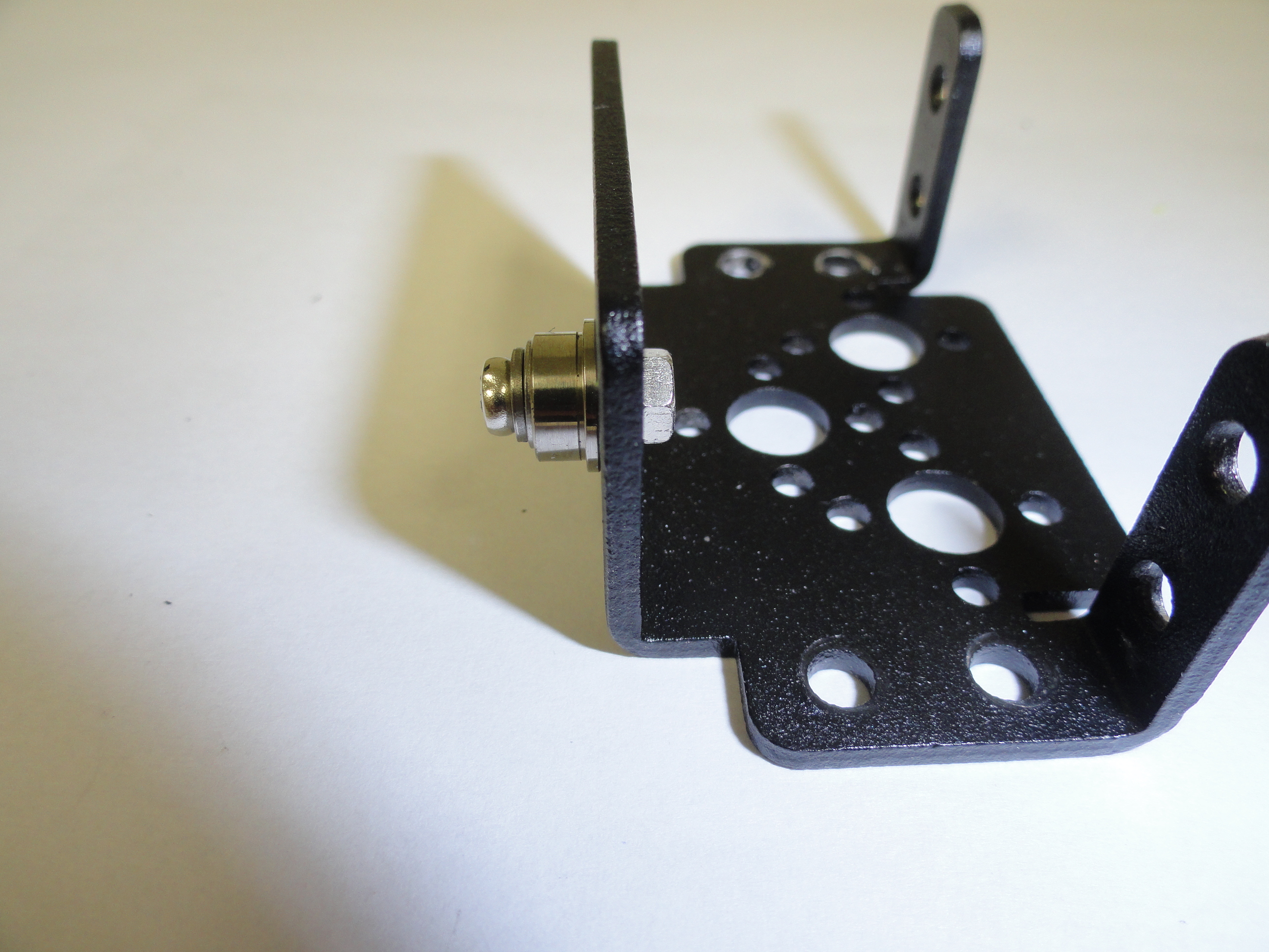
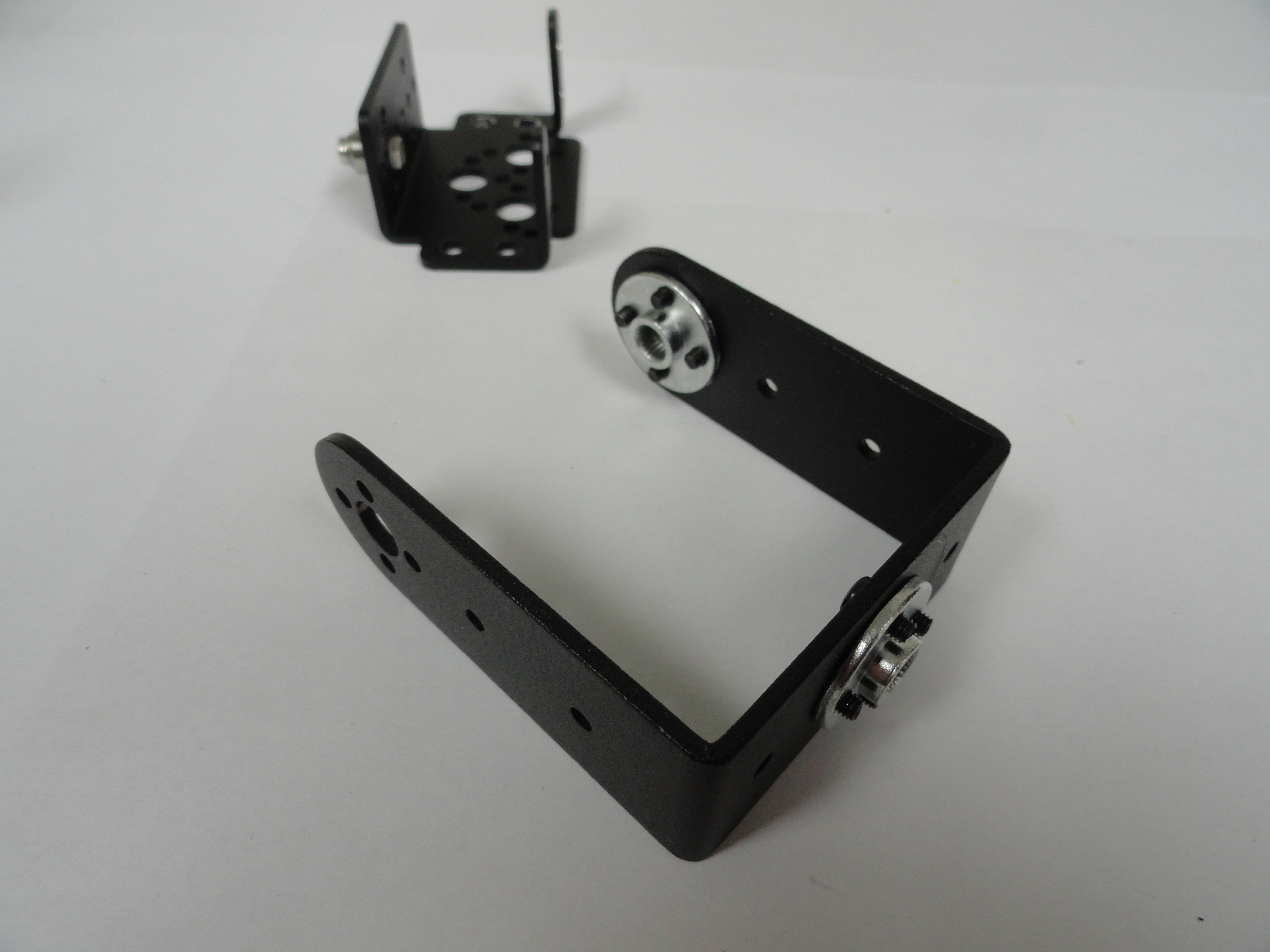
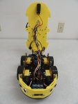
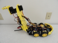
16) Install the first Servo. The Servo is installed under the top chassis and through the front rectangular hole. The Servo is oriented so the shaft is rearward of the hole. Install the Gimbal and the second Servo as shown. The 2 piece bearing goes into the hole opposite the 2nd servos shaft, then use the metal round pieces to attach the servo's with the provided black screws. To ensure the servos motion is correct, move the servos from side to side (or up and down) and determine where to slide the metal round piece so that it is in the middle of its travel. Each servo moves more than 180 degrees so you want a full 90 one way, and a full 90 the other. Once you have determined orientation, slide the shaft into the round piece and fasten. If you have never put together a gimbal before, it can be frustrating. Click on the pictures to get a good view of how it goes together.
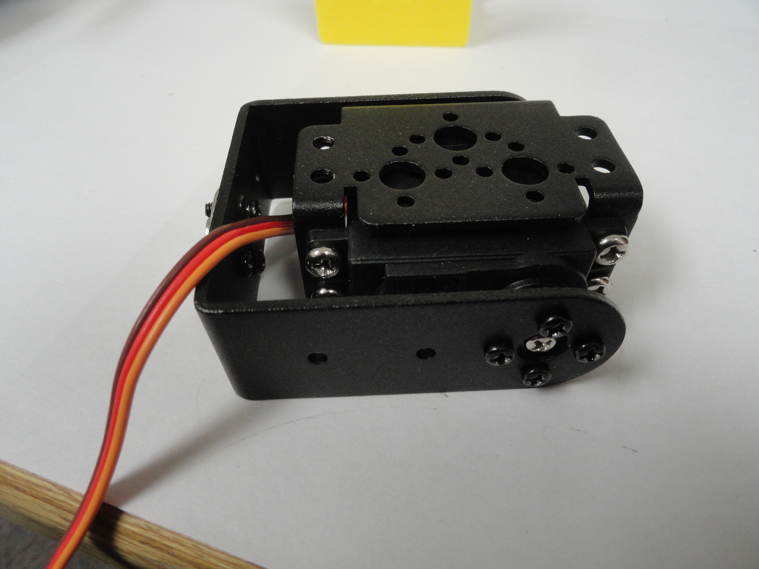
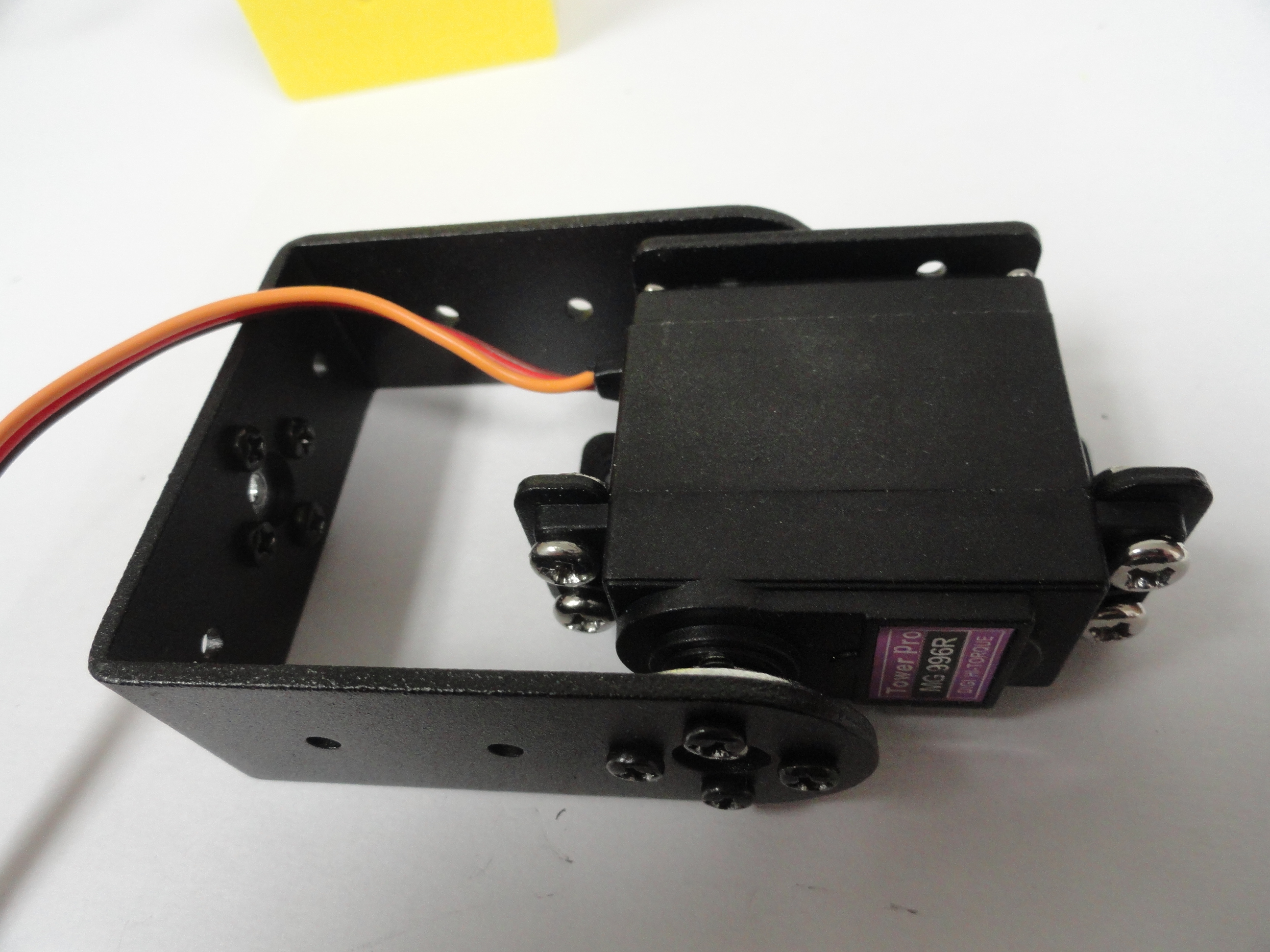
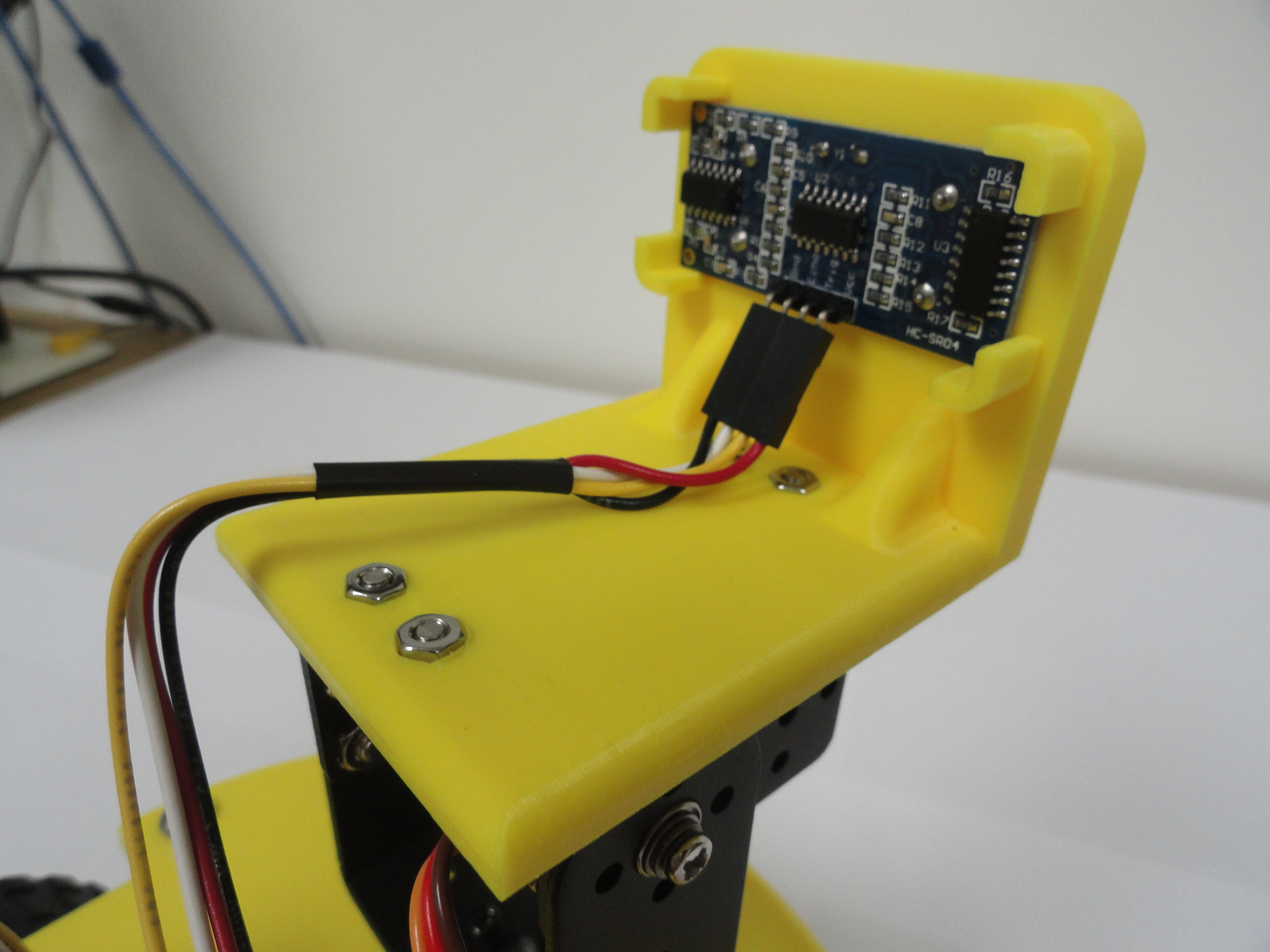
17) Install the HC-SR04 Sonar Sensor Bracket to the top of the Gimbal with the 4 8mm screws and nuts provided. Snap the sensor into place. If it is smiling back at you, you did it right! Install the wiring harness to the sensor following the Shield instructions above.
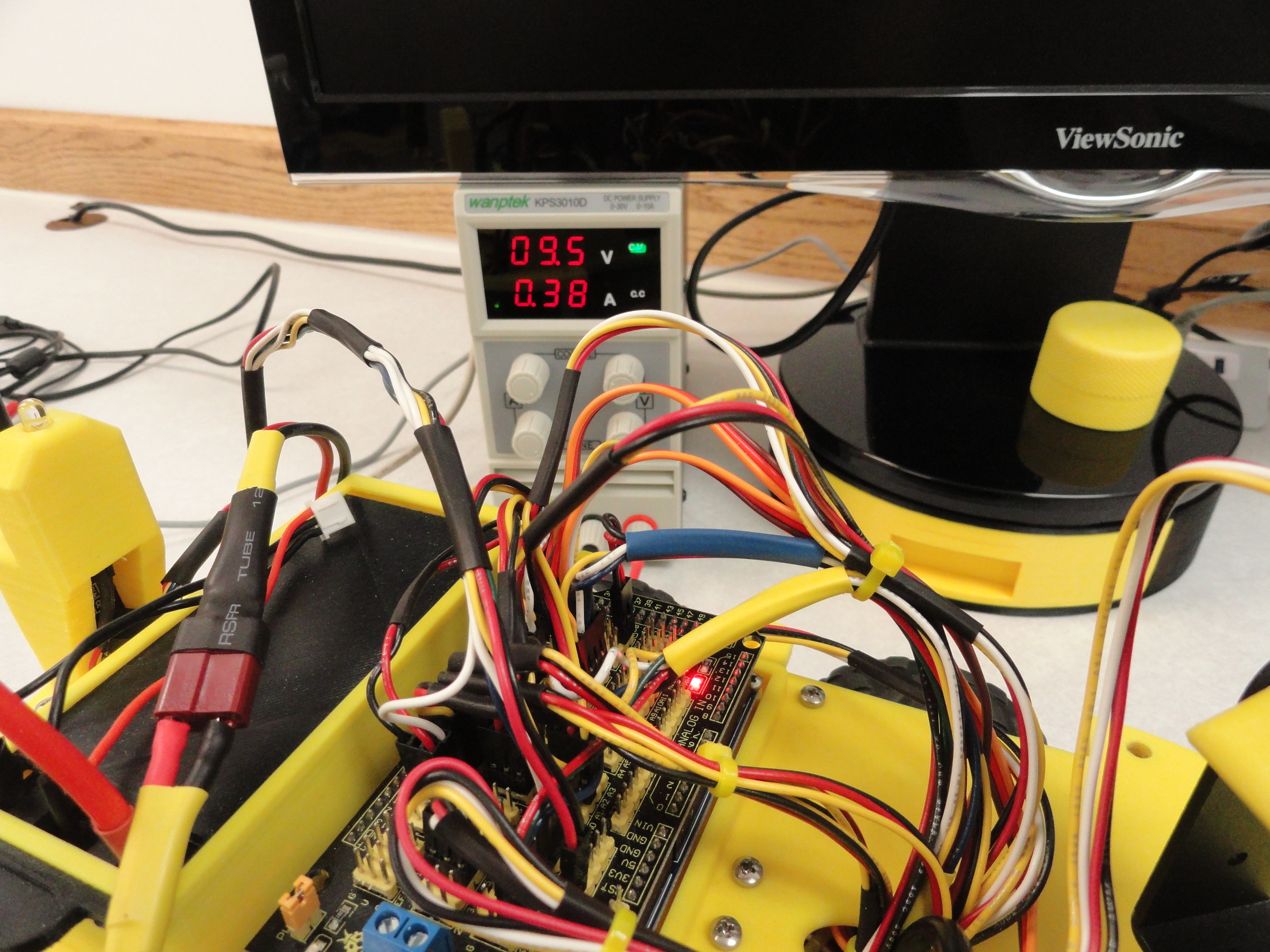
18) Flip the switch but be ready to flip it back off quickly! If the Arduino Sensor Shield's LED lights up and the two motor power
controllers have LEDs that are lit, you can leave it on and know that you have everything wired correctly enough to not cause a meltdown.
Once everything is nicely routed and all wires are secured, you can install the three screws on each side to secure the chassis down.
Assemble The Remote Control Unit
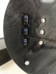
1) Route the switch wires through the round switch hole at the side of the chassis. Route the wires through the holes at the back end of the cavity through to the other side of the chassis where the battery will be placed. Connect the wires to the battery box. They are long enough to come out of the case for easy change of the Batteries. Install two 18650 batteries into the case, switch the battery case switch on (NOT the round switch yet) and place it into the battery box. Slide the cover over the battery. Place the switch cavity cover on the chassis and screw down with the 4 provided #4 x .75 Inch sheet metal screws.
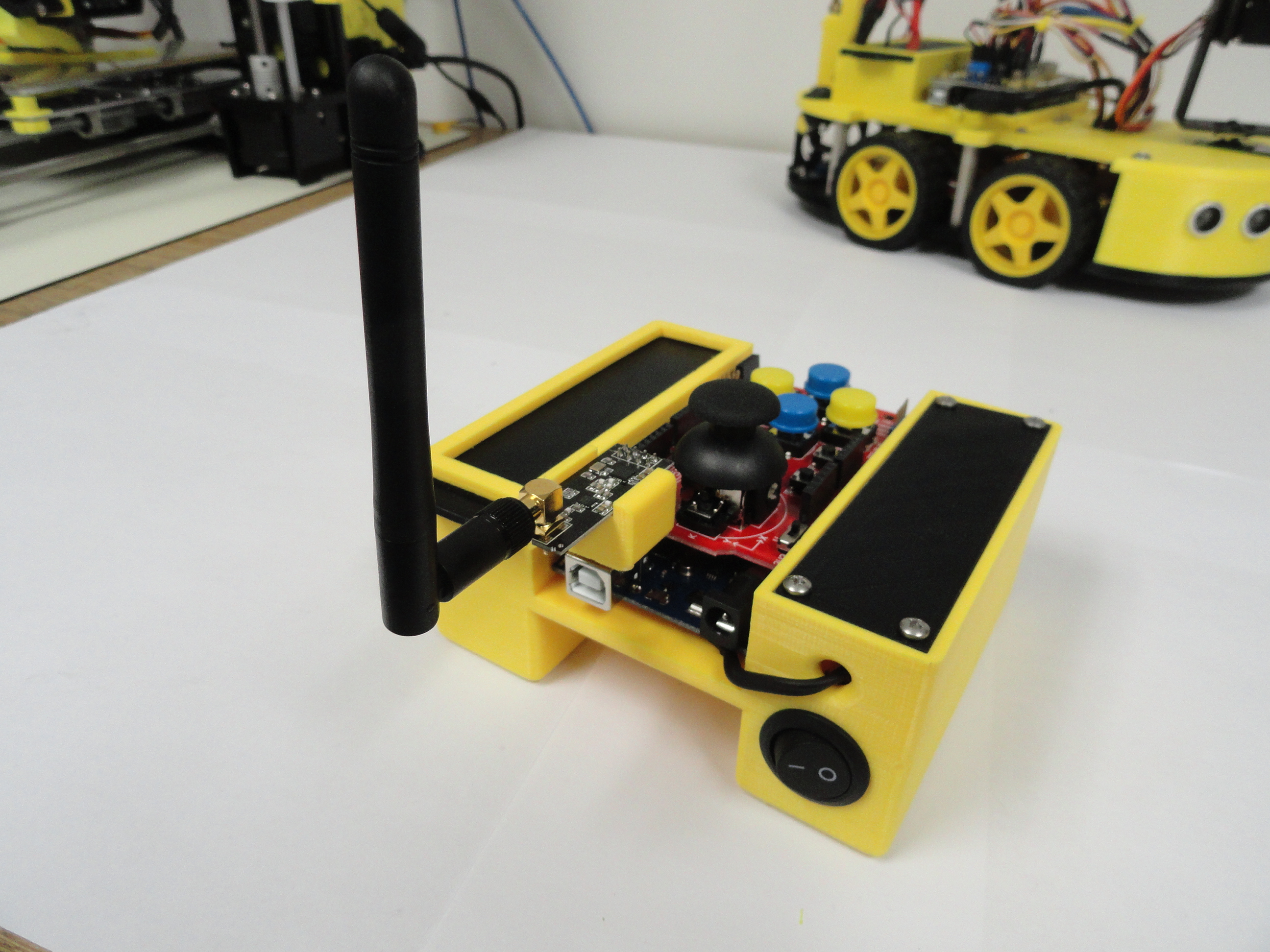
2) Set the Arduino Uno into place and match up the hold-down screw holes. Fasten with 4 2.5mm x 18 screws and nuts. Push down the Funduino Joystick Shield carefully onto the Uno's mating pins. Look closely to ensure all pins are properly mated.
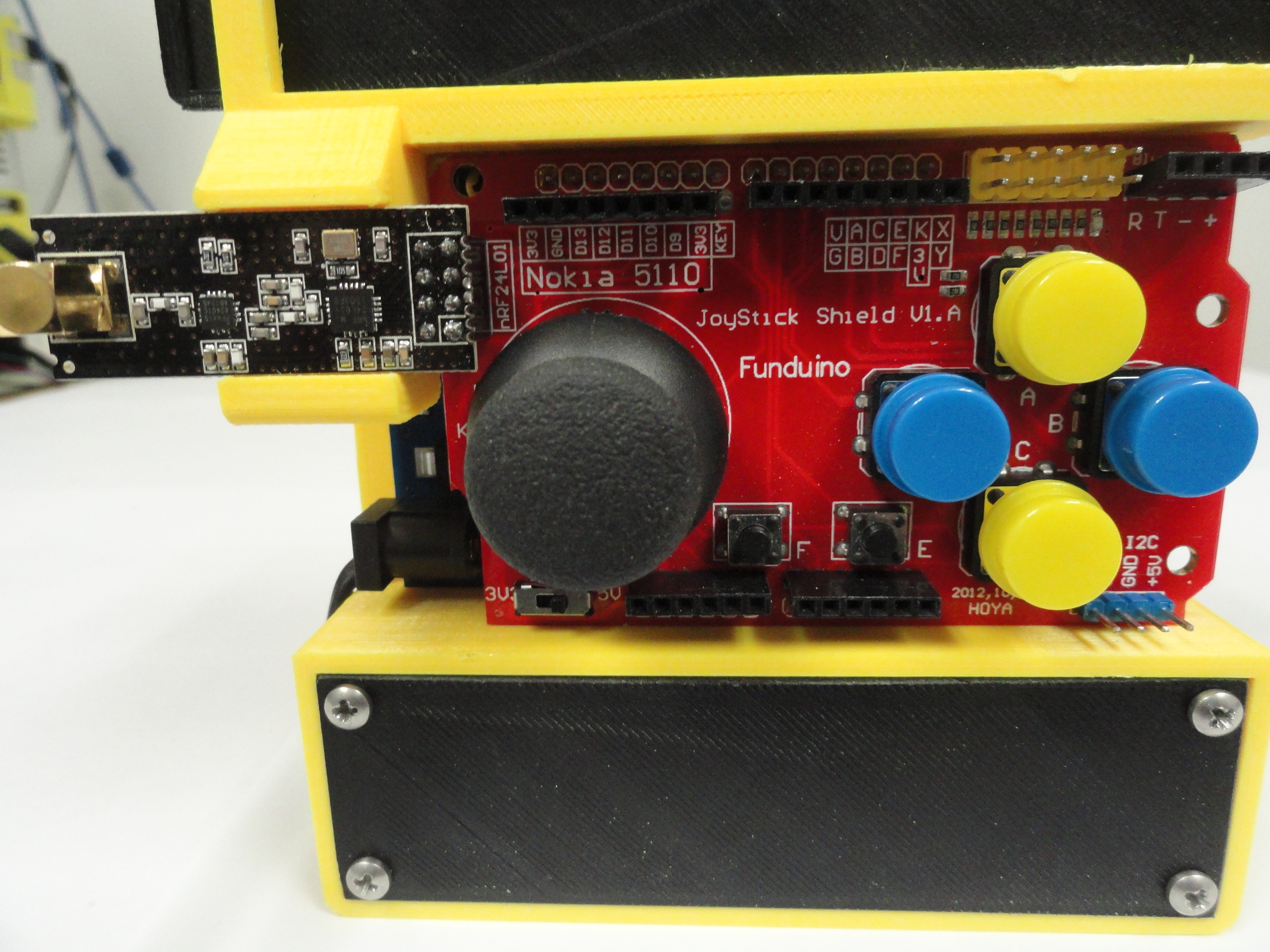
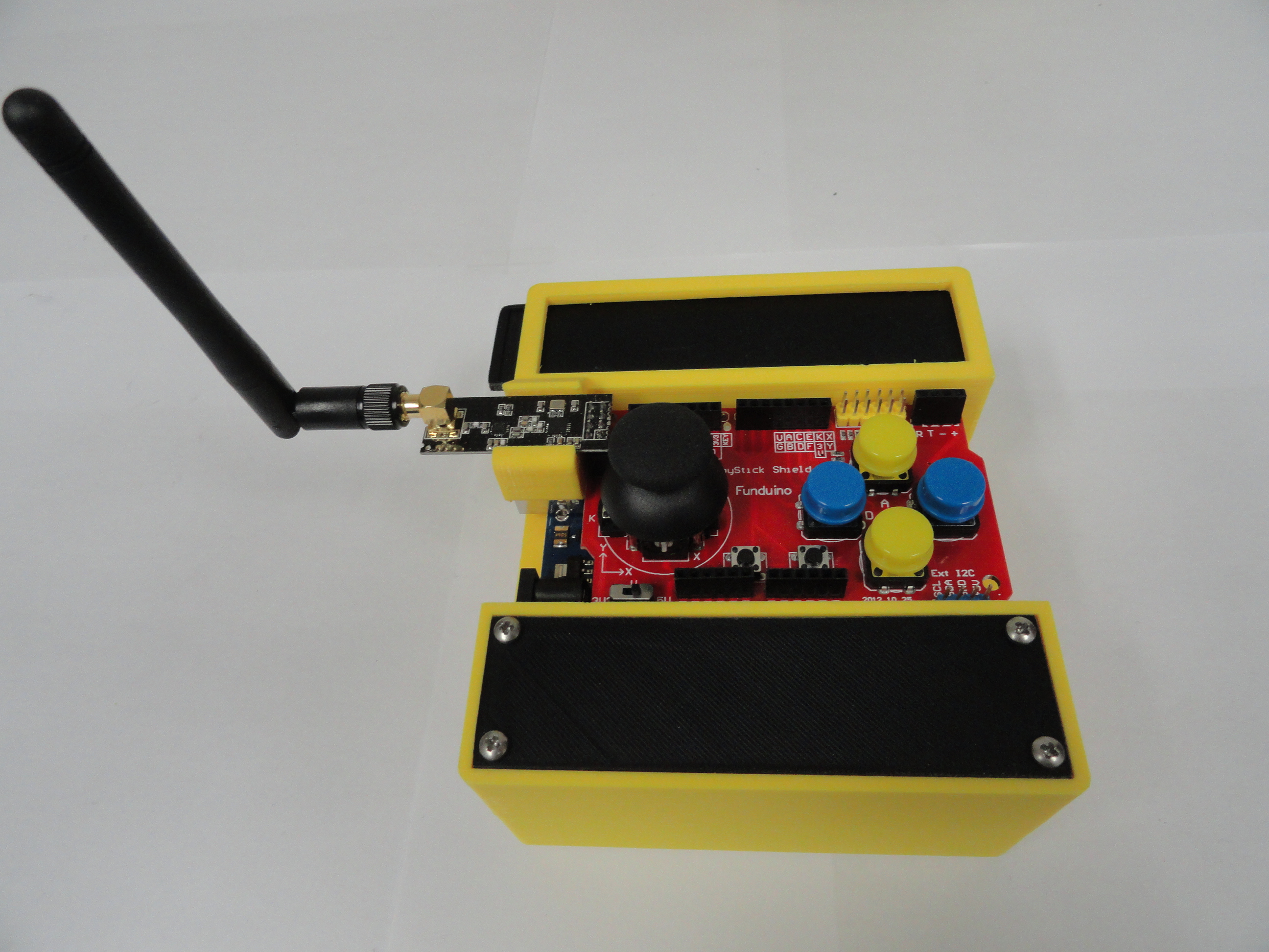
3) Plug in the NRF24 Radio Transceiver so that the small board rests on the chassis outcropping with the Antenna facing outwards and upwards. This gives a nice stable platform for the radio to rest.
4) Connect the power plug to the Arduino. Now on to the Software....
The Arduino Software!
You will want to download the following libraries for your Arduino Sketches. Libraries extend the use of the Arduino by adding
really advanced features to your projects. Here are the library downloads required:
NRF24 Radio Library - Used to handle the Long Range Transceivers.
SPI Library - This is a standard library already installed with your Arduino IDE Software.
PWMServo Library - This is a special servo library that is
necessary because the original servo library doesn't play nice with some of our other programming code.
Prior to taking your Car out on its first run, it is imperative that we ensure the wiring is correct. To accomplish this, we made a
series of test programs that work independently of the main software system. The first one of these is to check the motor control.
Place the car on a block of wood or something that will get the wheels off the ground, then run the MotorControlTest Program provided
here. Unzip and place in your Arduino/Sketches folder:
Arduino Mega Dual Motor Control Tester
If the wheels all turn the same way, you are good to go. However, if they do not do what the program indicates, swap the red
and black wires from the motor at the controller terminals. Do not be tempted to swap the software IN switches! All that does is
change variables that are needed a certain way for the main program to work.
ALSO.. be sure that the long 6 pin connector has the Black wire nearest the Controllers power terminals. VERY important! Double
checking these connections will save you from hours of head scratching!
The next thing you will want to address is the proper movement of the Servo's on the Servo Gimbal. This is essential to its proper
operation as well as prolonged battery life. These hobby servos have a serious flaw in that they do not know where their limits are.
This presents us with an opportunity to custom set each servo so that the servo doesn't cause a high amperage situation. Do NOT think
the servo's automatically know 0 and 180 degrees! The following program will guide you in setting them up. Read the comments at the
top of the program to understand how it works. Unzip and place in your Arduino/Sketches folder:
Dual Servo Calibration and Tester
Once you have both Pan and Tilt Servos set so that the sweep is in the center of the car and there are no odd noises coming from the
servos when they reach their limits, you are good to go.
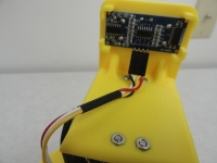
Now we look at the large Sensor Array on this beast! Let's start with the Rear IR sensors. These are FC-51 Infrared Sensors. The
white LED is the transmitter and the darker one is the receiver. They have a distance of 2 - 30cm or 3/4" to 11-3/4" Detection Range
and are quite reliable. These are merely used to stop the car before it hits anything, so the distance is more than enough. Be sure
the LEDs are not bent, rather face straight outwards evenly for best performance. You adjust the distance by turning the potentiometer
clockwise to increase, counterclockwise to decrease. If you adjust them and the detection LED on the sensor stays on, you adjusted
it too far. Unzip and place in your Arduino/Sketches folder:
Arduino Mega FC51 Rear IR Sensor Tester
The front fascia has three sensors on it. We will concentrate on the middle one next. For front obstacle avoidance, we chose the
Sharp 2Y0A21 IR Proximity Sensor. This sensor has a 10 - 80cm or 4" - 31" detection range. While it is not very accurate for
exacting distance measurements, it will easily fulfill its purpose of front obstacle avoidance. Unzip and place in your Arduino/Sketches
folder:
Sharp 2Y0A21 Proximity Sensor Tester
Now let's address the HC-SR04 Sonar Sensors. There are three on this project. Two front 45 degree facing sensors on the front fascia,
and one mounted on the dual axis gimbal. Along with the stationary front facing Sharp 2Y0A21 above, the front is well sensored! The
advantage of putting one of our HC-SR04 Sonic Sensors on a Gimbal is to be able to detect staircases, or other dropoffs and deal with
these dilemmas before bad things happen.
The program below completely tests each HC-SR04 Sonic Sensor both individually and together. By using the Servo system to test, we
can emulate a dropoff by putting the car on a table with the sensor sweeping half-on and half-off the edge of the table. It is also
important to get a Library called NewPing. Click on the download button on the Arduino Website
HERE for your copy. Then place it in
C:\Program Files x86\Arduino\Libraries (or your proper path). Unzip and place this Sketch in your Arduino/Sketches folder.
HC-SR04 Sonic Sensor Tester
The last sensor array we will have on the car (for this first go-around anyway) will be the FC-03 Infrared Barrier Line Tracking
Sensor. There are three of these sensors facing downwards under our SuperSmartCar. These are there so we can make our own
racetrack and have the car just follow a 3/4" black line. So happens, most electrical tape sold in America is 3/4" and its pretty
cheap! These sensors work really well but you have to have contrast. A White background will give you the best chance of success.
I have included a paper template that you can print out for the straightaway. It is in standard jpg format and available
HERE. It will NOT work by itself. You MUST run a line of Black Electrical
Tape across the page. The Sensor only picks up Reflective Black.
The FC-03 sensors work the very same as the FC-51's we have for the back of the car, only these are made to detect much
closer activity, in this case color contrast within less than an inch. They are probably calibrated fine from the factory, but if not
they come with a potentiometer that you can adjust for more sensitivity. Print out the above jpg so you can swipe it under the car
for testing to see if all three sensors are performing as they should. Swipe the long black line under the car, side to side and take
a look at the Serial Monitor. Unzip and place this Sketch in your Arduino/Sketches folder.
FC-03 Sensor Tester
With all of the Sensors aside, we can now concentrate on the Radio and Controller system. First we should make sure the Funduino
Joystick Shield for the Arduino Uno used for the controller is working perfectly. We will test all of the buttons and the joystick
for proper operation. There are 6 momentary buttons labeled A through F and 1 momentary switch available by pushing down on the
thumbstick. The thumbstick will provide a 0-1023 analog span with its rest point in the middle for both X and Y Axis. This is a
necessary test because sometimes they get damaged in shipment so its a good idea to test your shield. Remember to change the Board
and Port in the Tools Menu of the IDE. Unzip and place this Sketch in your Arduino/Sketches folder.
Funduino Joystick Shield 1.1A Tester
Now for the moment of truth! If you did everything right, and I did everything right in explaining all this, you can download the latest
Super SmartCar software and start enjoying the integration of all of the components! These programs are not perfect yet. They are still under
development. My sincere hope is someone with more programming experience than I have can create better software for this project. ANYONE having
a better idea, please contact me. I will be happy to incorporate your suggestions into the main code. The SLAVE, or Receive Code goes to the Car,
and the MASTER or transmit code goes to the Controller!
Controller Side Master Software
Super SmartCar Side Slave Software
1) Connect the Super Smart Car Arduino Mega to the computer with the Arduino IDE software. Verify then Upload SuperSmartCarSlave to the Car. Check that the correct Arduino Mega and proper Port is chosen in the IDE before trying it. You can leave the Cars power switched off for this. The USB connection will power the Arduino Mega for the process.
2) Connect the Remote Controller's Arduino Uno to the computer with the Arduino IDE software. Verify then Upload SuperSmartCarMaster to the Controller. Again the Battery power can be switched off because the USB connection to the computer will provide power for the process. Hold the Controller so the Antenna is to your left. This situates the X and Y axis appropriately. Once completed, follow this standard procedure for powering your new learning tool...
- Switch on the Remote Controllers power switch. The LED light will illuminate on the Uno (under the shield) verifying you have power to the Micro-Controller.
- Switch on the Super Smart Car. The LED on the cars radio tower will Strobe verifying the Car sees and understands commands from the controller.
- Play with the controls! Thumbstick forward should be Car forward on all four motors. Back equals backwards, Left equals left turn, Right equals right turn. Push down on the thumbstick and it will do a zero turning radius turn.
The software is in development and there is much more to this. Three modes of operation will be possible using the same program. Tracking mode will follow a black taped track on the floor. Obstacle Avoidance Mode will not use the remote controller at all, rather, it will just go out in to the room, find the walls, turn and move to the next obstacles, sort of like a Roomba. It will also be able to see stairs and keep the car from falling. This mode will be the most fun since it will act like the family dog and just roam. Then of course there is the remote control mode. The software should be switchable from mode to mode via the remote controller.
Software Control Features
Currently the software has three modes:
- Obstacle Avoidance, Remote Control
- Collision Avoidance, Remote Control with Staircase Protection
- Line Following/Tracking Mode
There are two LED's sticking up off the Mega's Sensor Shield that provide information as to the current operating mode.
On powerup, the two lights on the sensor shield should be off. This is Mode 1 or Obstacle Avoidance/Remote Control mode.
Pressing down on the E button on the Controller will cause the Tilt Servo to move to 30 degrees (facing downwards) allowing
the Gimbals Sonar Sensor to see below the floor's surface. (as in upcoming staircase). The Red LED on the sensor shield will
illuminate to confirm your choice.
To enter Line tracking mode, press down on the thumbstick. The Yellow LED on the sensor shield will illuminate to confirm
your choice.
Troubleshooting
There are many factors that explain why your SuperSmartCar is not performing as it was designed. Here are a few ideas to help.
1) At no time can there be a ground wire (black) in the positive +5volt line. All voltages both Power(red) and Ground(black) MUST be
oriented correctly. One mistake and you will burn out sensors or even the Mega itself. Be very exacting in your connections!
2) It is essential that you read and understand the pin connections for each connector. The only way this works is if all connections are
made according to the instructions.
All controllers and sensors are tested prior to packaging. Time is taken to ensure your experience will be a pleasant one, however, if after
you have checked and double checked the wiring, and you are still having problems, contact us via email deve@devestechnet.com.
Purchasing the 3D Printed Parts
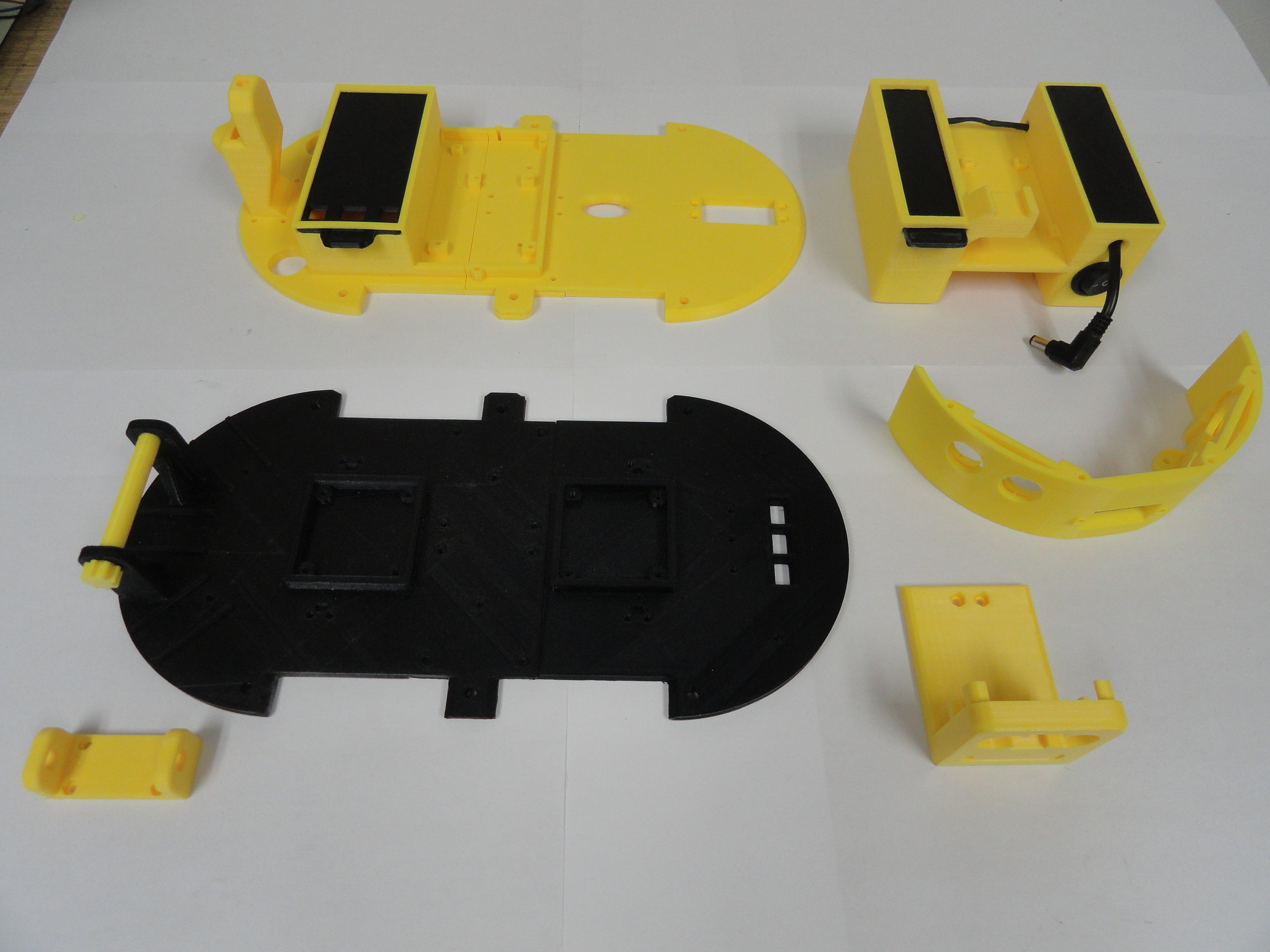
For those of you that are unfamiliar with 3D Printers, they are very very slow. Each of the 4 halves takes a minimum of 30 hours to print. The remote control housing takes 54 hours. The point being.. not only was the original design challenging, but the printing is very time consuming, thus why this kit is expensive. Then, due to the time factor and limited number of 3D Printers, each kit is made to order. This puts each kit at least 2 weeks from shipment to your door. Be patient and you will be very satisfied with the end result.
The Options available below are:
- 3D Printed Parts Kit - This is all of the 3D Printed Parts in the picture above. Screws are included for putting the halves together.
- Full Super SmartCar Kit - This is the entire project kit. It comes with all sensors, micro-controllers, shields, everything you need to build this project including wiring harnesses. Also Includes Arduino Software Code.
- Wiring Kit Only - This is all of the wiring harnesses all put together ready to plug in to the parts. Includes the two power switches.
All transactions are done through PayPal. Email deve@speedprint.com for International Shipping Rates.
Why is this so expensive?
We 'could' have used an Arduino Uno on this project thus a smaller Shield. We chose the Mega 2560 because if you are taking a plunge like this, you want the expandability of more pins and more memory. We 'could' have gotten away with a single motor controller and just ganged the left and right together. I hope you can appreciate the more robust concept of one motor, one controller output. We 'could' have used less sensors, or all of them the same kind. We hope as a learning tool, you can appreciate that we gave you various types of sensors to experiment with. We 'could' have used the smaller Micro Servos with a smaller Gimball. These were chosen for their strength and durabilty. We 'could' have used Bluetooth or Wireless modules instead of the NRF24 Radios. We did one better and chose the highest output NRF24 Radios with their own Antennas for very long range work. So, remember if you build this yourself, the cost adds up but in the end, we wanted to provide you with a kit that was worth every penny!


