Introducing The Super PiCam
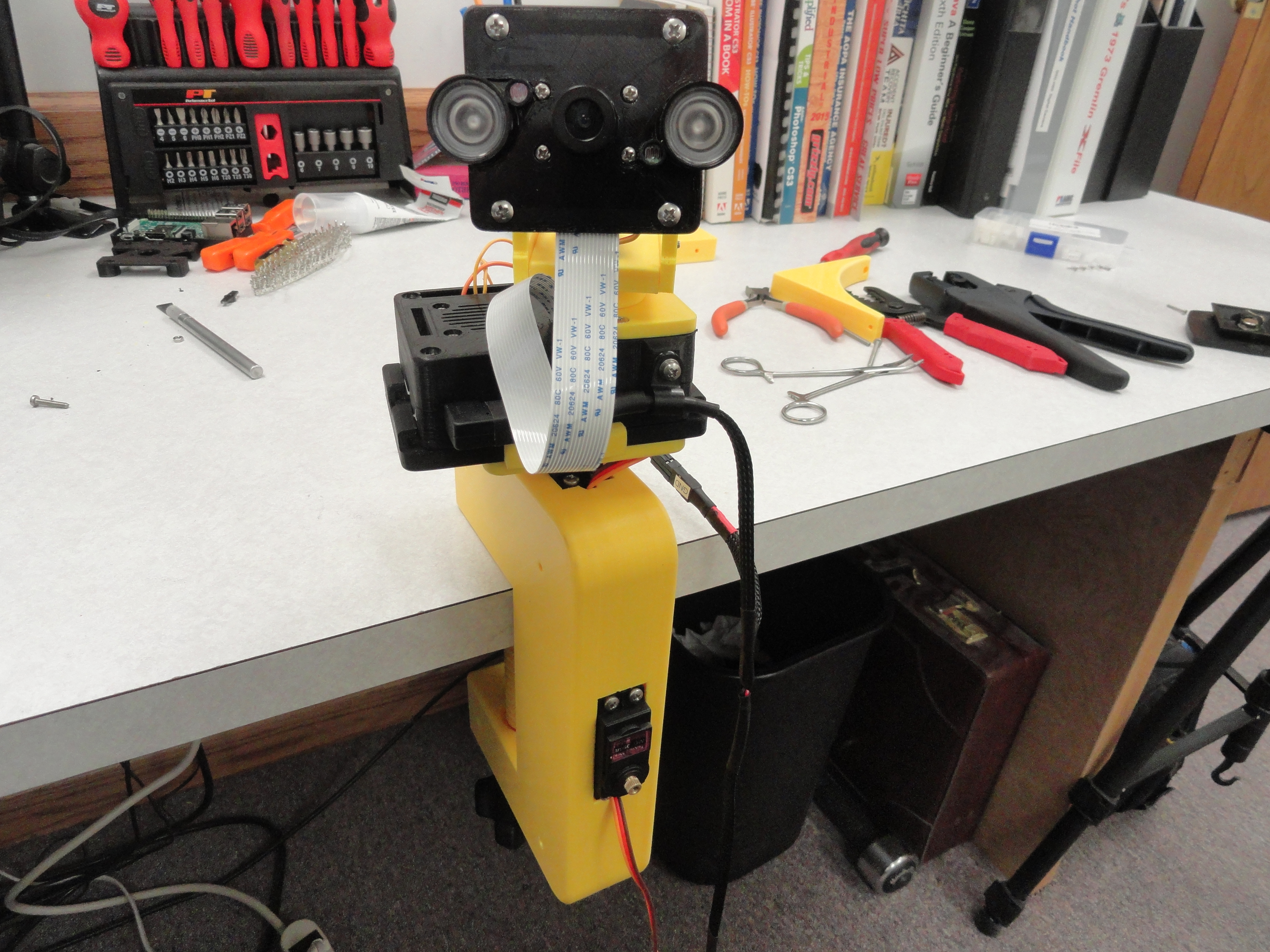
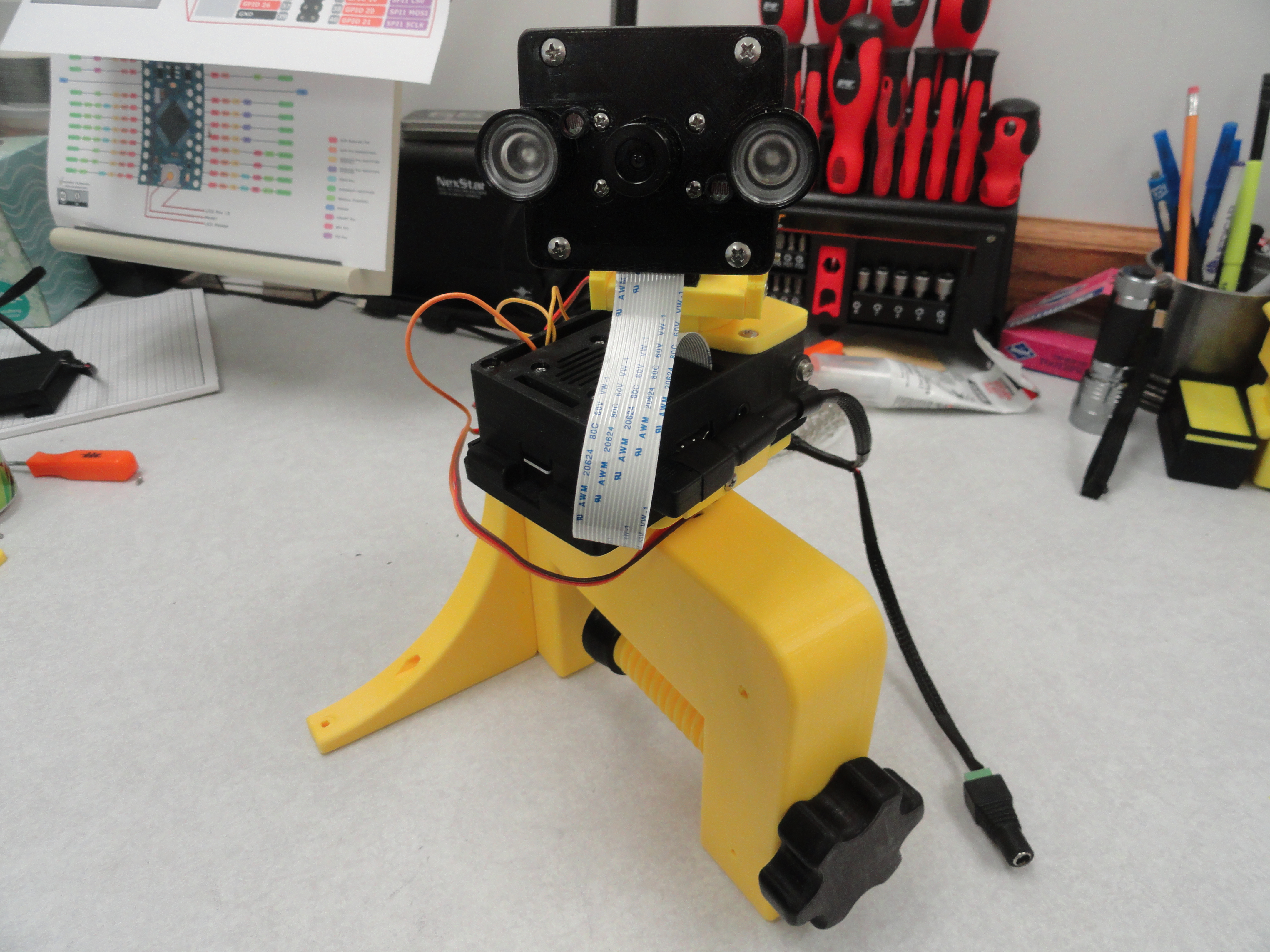
This project was originally inspired by Parents of small children. We wanted a Baby Cam that could monitor a young child's room. Some of the problems we encountered had to do with mounting the camera. There are so many options for that and depending on where you choose to put the camera had a lot to do with how much of the room the camera would cover. The PiCam was a good choice because it has both Day and Night Vision with a 120 degree field of view. But what if you want to see behind the camera? Maybe you want to center that 120 degree field of view on something else in the room? So, to resolve that in the best way we know, we use three mini Servo's. One is for Tilting the PiCam from directly down to directly up. One is for Pan from left to right, and the last servo is for turning the entire kit 180 degrees (the Pan axis) so every degree of the circle is covered!
Then we needed a way to get the real time audio or video feed to you in the best way possible. Since it uses a Raspberry Pi 3 for its intelligence, we can use wireless Local Area Network connectivity. Now you can see the feed on your SmartPhone, Tablet or Computer. But seeing and hearing is not enough! We also want to be able to control the movement of the camera via the LAN. So we originally put Sliders at the bottom of the display so you can control, in real time, the movement of the PiCam. This proved to be too coarse of a method and thanks to Richard Hirst, he came up with a FAR better idea. On a smartphone or Tablet just SWIPE! On a computer, just use the mouse to swipe, or use the keyboards arrow keys. Now we have a very smooth way of moving the camera!
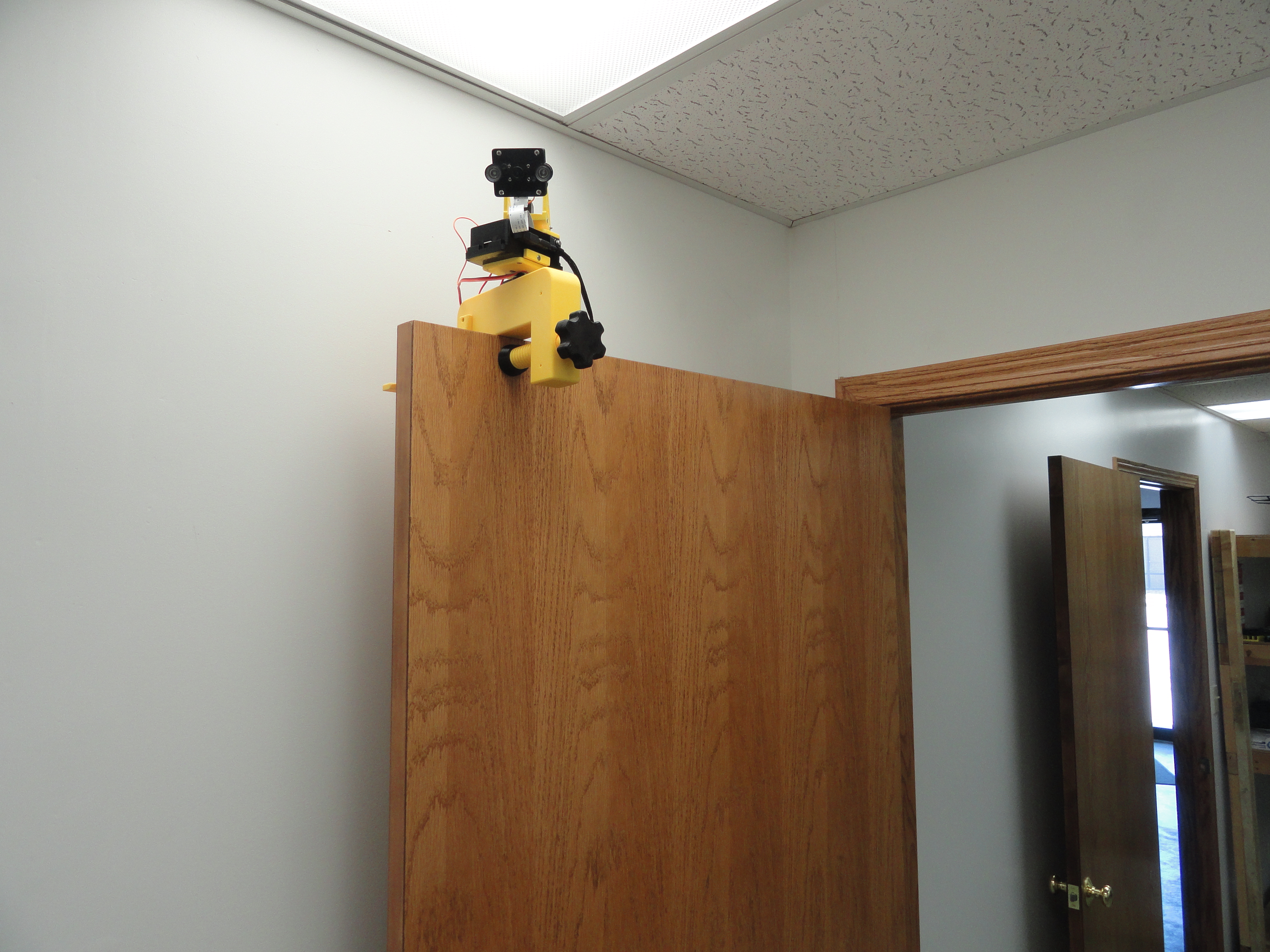
Mounting options are an ongoing issue, but we currently have three methods. One is to clamp the Kit to any surface like the edge of a table, bookshelf, Crib, etc. Another is to slide the kit on to an 11-1/4" industrial HVAC duct. We also made a plate that screws to a wall, ceiling, or any surface for a more permanent solution. We encourage you to email us with your suggestions.
That gets us day and nightvision, via the LAN on any computer or device on your network, but we also want to hear what is happening in the room. We decided on the Adafruit I2S MEMS Microphone Breakout - SPH0645LM4H. The reason for this choice is the Raspberry Pi does not do Analog very well and this is a fully digital solution. Since it is actually smaller than a postage stamp, we can mount it on the PiCams face mount which provides us with directional capability. Just point the camera to the thing you want to hear in the room!
Complete Parts Listing
If you are going to use the 3D Printed Parts offered later in this article, do not deviate from the list. All parts are available on Ebay. The links may not be active, but they will give you an idea on what to search for. Hardware is all Stainless Steel and available at McMaster-Carr.com.
- 1 - Raspberry Pi 3 Model B
- 1 - Raspberry Pi Camera with Night Vision IR
- 2 - MG996R Servos - This is the large servo that mounts to the Pi.
- 2 - MG-90S Servos - All servos have metal gears.
- 1 - 6mm (or 1/4") Cable Strap for the Case
- 1 - 90 degree (LEFT) USB Micro Adapter
- 1 - 20cm PiCam Ribbon Cable The one that comes with the PiCam is too short.
- 1 - 30mm x 30mm x 7mm Case Fan 10mm is too wide.
- 1 - SPH0645 I2S Digital Microphone This is a fully digital solution.
- 1 - Wago 5 Pole Bridges Perfect Terminal Solution for this application.
- 1 - Hold-down Screw for fastening the Propeller to the Large Servo - 3mm x 8mm
- 6 - Propeller Hold-down Screws - #1 x 3/16" (5mm)
- 4 - Servo Mount to Pi Case Receiver - 3mm x 10mm w/ Hex Nuts
- 1 - Receiver Lockdown Screw - 3mm x 20mm w/ Square Nut
- 2 - Pi Case Rear Screws - 3mm x 25mm w/ Hex Nuts
- 2 - Pi Case Front Screws - 3mm x 35mm w/ Hex Nuts
- 4 - Pi Case Fan Screws - 3mm x 16mm w/ Flat Washers and Hex Nuts
- 1 - Pi Case Cable Strap Hold-down Screw - 3mm x 6mm w/ Square Nut
- 4 - PiCam to Face Plate - 2mm x 8mm w/ Hex Nuts, Flat and Lock Washers
- 4 - Picam Face Plate to Gimbal Mount Screws - 3mm x 12mm w/ Hex Nuts
- 2 - Microphone Breakout to Face Plate - 2mm x 8mm w/ Hex Nuts, Flat and Lock Washers
- 1 - Gimbal base to Gimbal Side Rails - 3mm x 50mm w/ Hex Nut
- 2 - Gimbal base to Gimbal Side Rails - 3mm x 16mm w/ Hex Nuts
- 4 - Servo Hold-down Screws - 2mm x 8mm w/ Hex Nuts, Flat and Lock Washers
- 2 - Servo Propeller Screws - 2mm x 8mm w/ Hex Nuts, Flat and Lock Washers
- 2 - Hold-down Screws for fastening the Propellers to the Small Servos - 2.5mm x 4mm
- 2 - Microphone Hold-down Screws - 2mm x 8mm w/ Hex Nuts, Flat and Lock Washers
- 100 - 2.5mm Hex Nuts
- 100 - 3mm Hex Nuts
- 100 - 3mm Square Nuts
- 100 - 2.5mm Flat Washers
- 100 - 3mm Flat Washers
- 100 - 2mm Lock Washers
- 100 - 3mm Lock Washers
Assembly
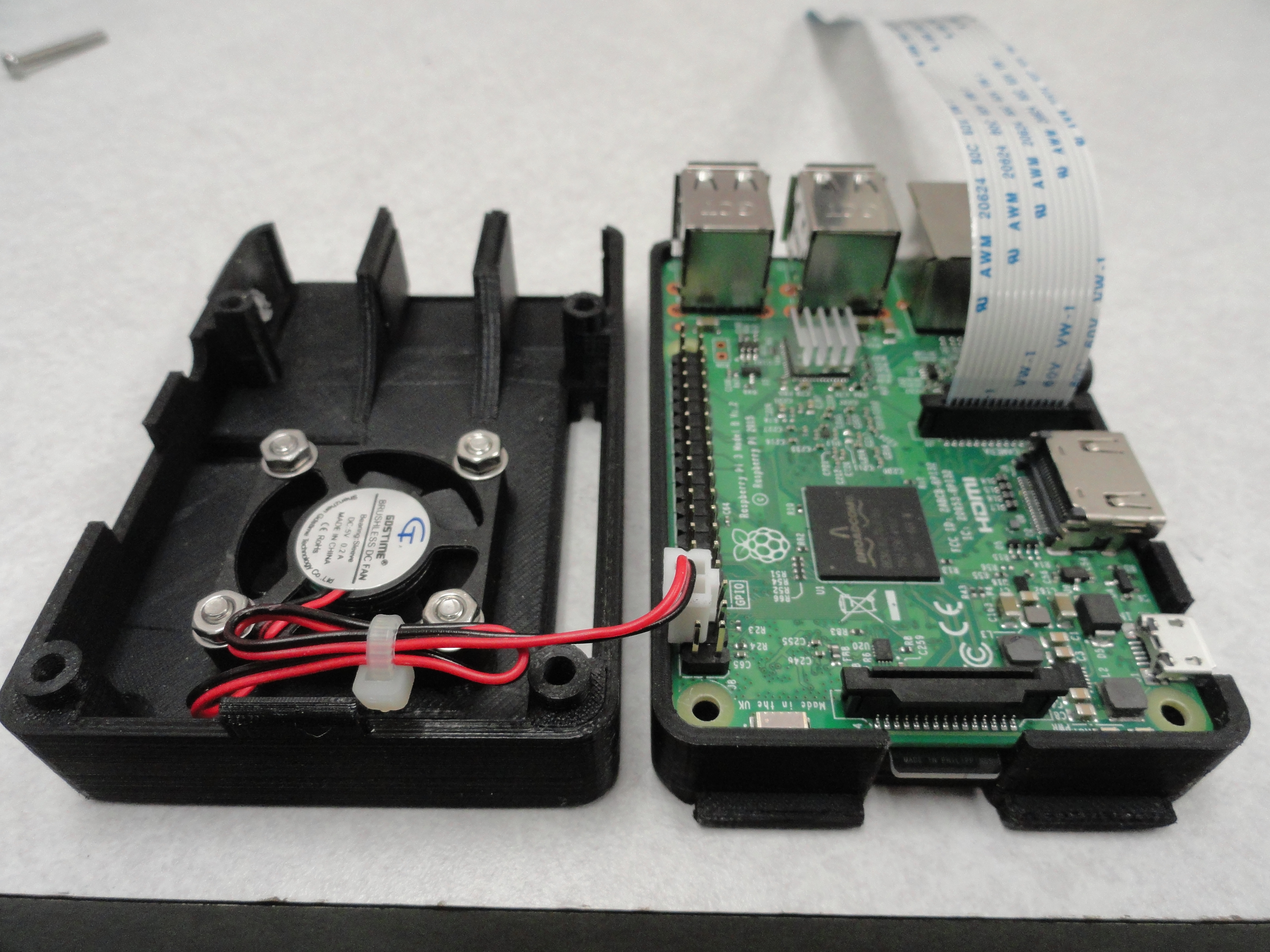
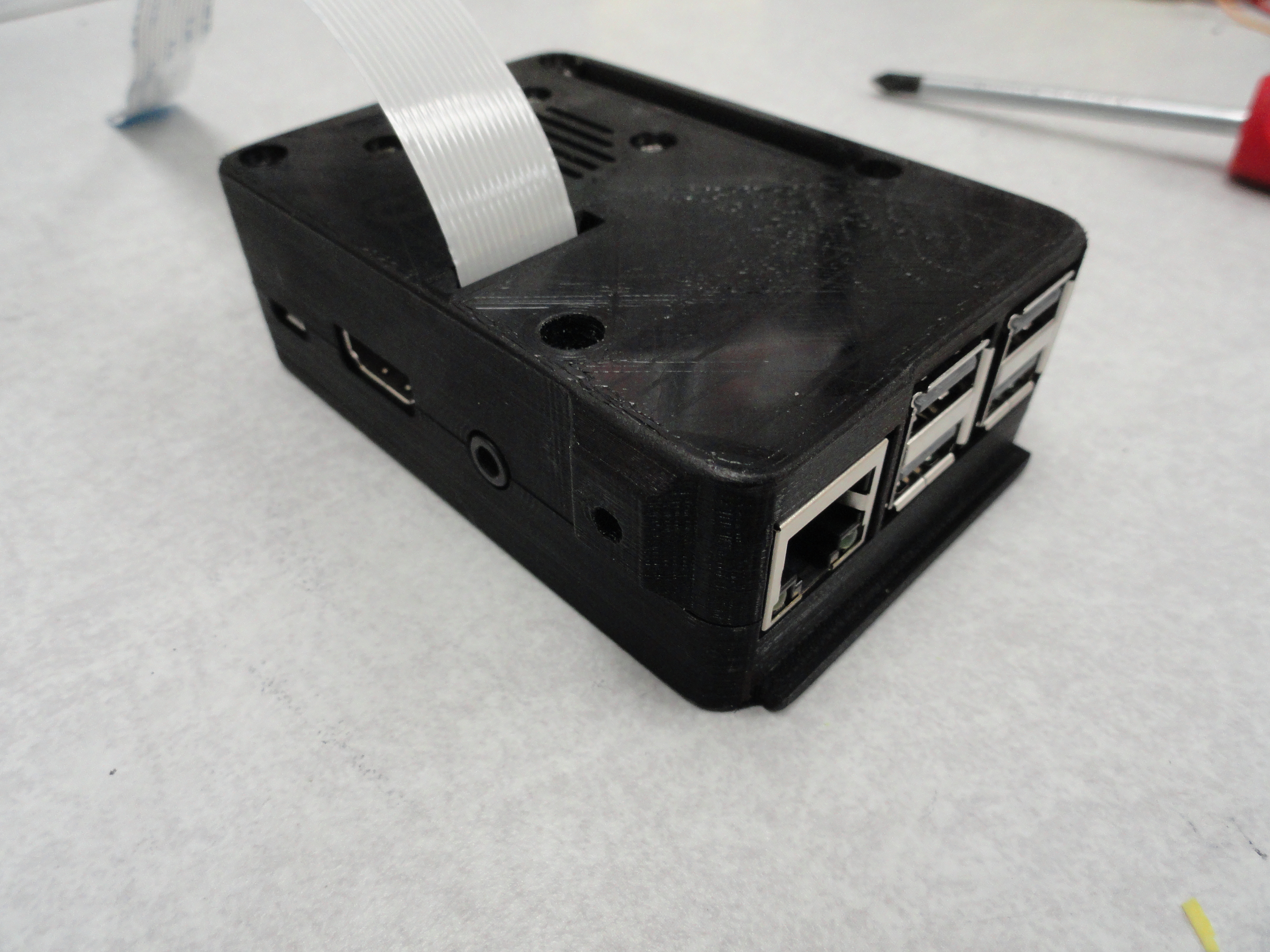
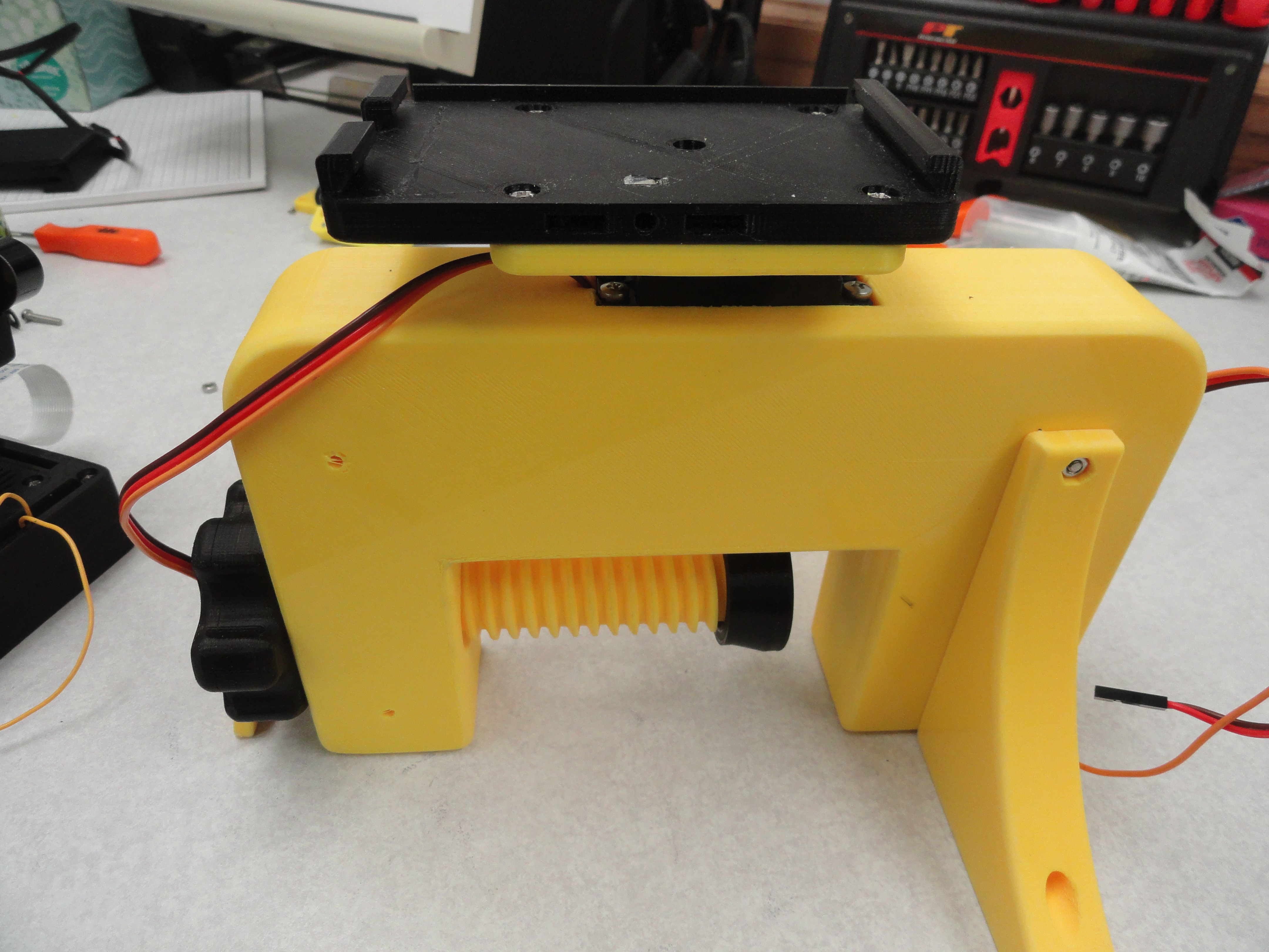
The 200mm ribbon cable needs to be installed in the Pi Case before closing it. This Pi Case system includes a 30x30x7mm cooling fan right over the main processor and everything fits very smoothly. If you have issues with getting it closed, you are pinching a wire or something. Take a closer look. Notice the tabs on the base of the Pi Case. They will slide into a receiver that locks the Case down to the rest of the system.

The Microphone wires also need to be connected through the large GPIO Connector opening prior to closing up the Case. At least it's easier that way. These wires are special in they are
made of Silicon and provide for a much more flexible solution. The wires are 14 inches (355mm). The wires are color coded as follows:
- Red - 3.3 volts (Pin 1)
- Black - Ground (Pin 9)
- White - BCLK (Pin 12/GPIO18)
- Green - DOUT (Pin 38/GPIO20)
- Yellow - LRCL (Pin 35/GPIO19)
- Gray - SEL (Not used for Mono Operation)
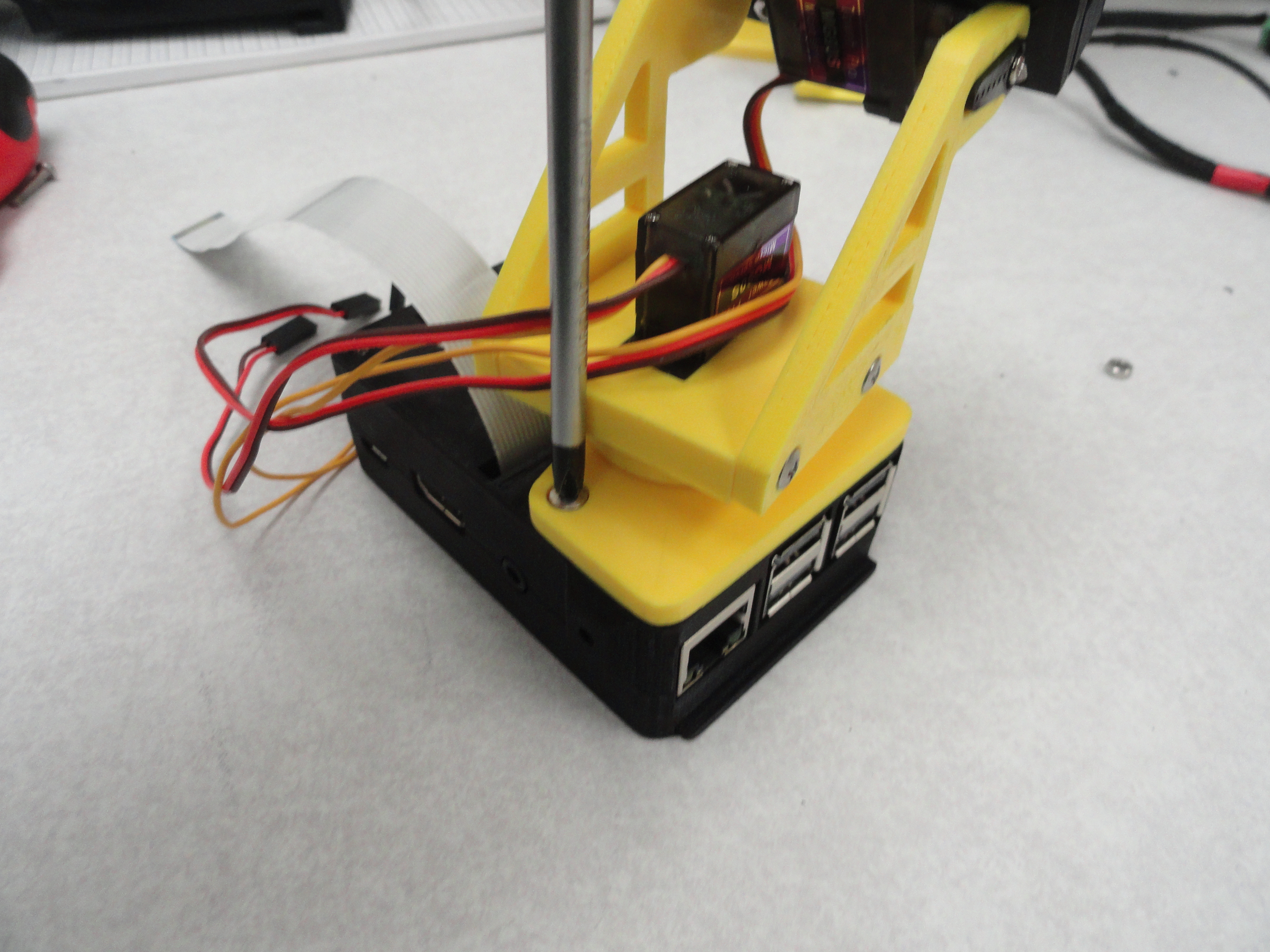
Two of the four Pi Case screws that hold the two halves together also serve as hold-downs for the Servo Gimbal. The Case is made to accept a certain length of screw that is perfect length for each part. If there are threads sticking out, you may be using the wrong screws. The front ones which also hold the gimbal are 3mm x 35mm and the ones in the rear are 3mm x 25mm all using 3mm hex nuts. Turn the gimbal as shown to get better access to the screws.
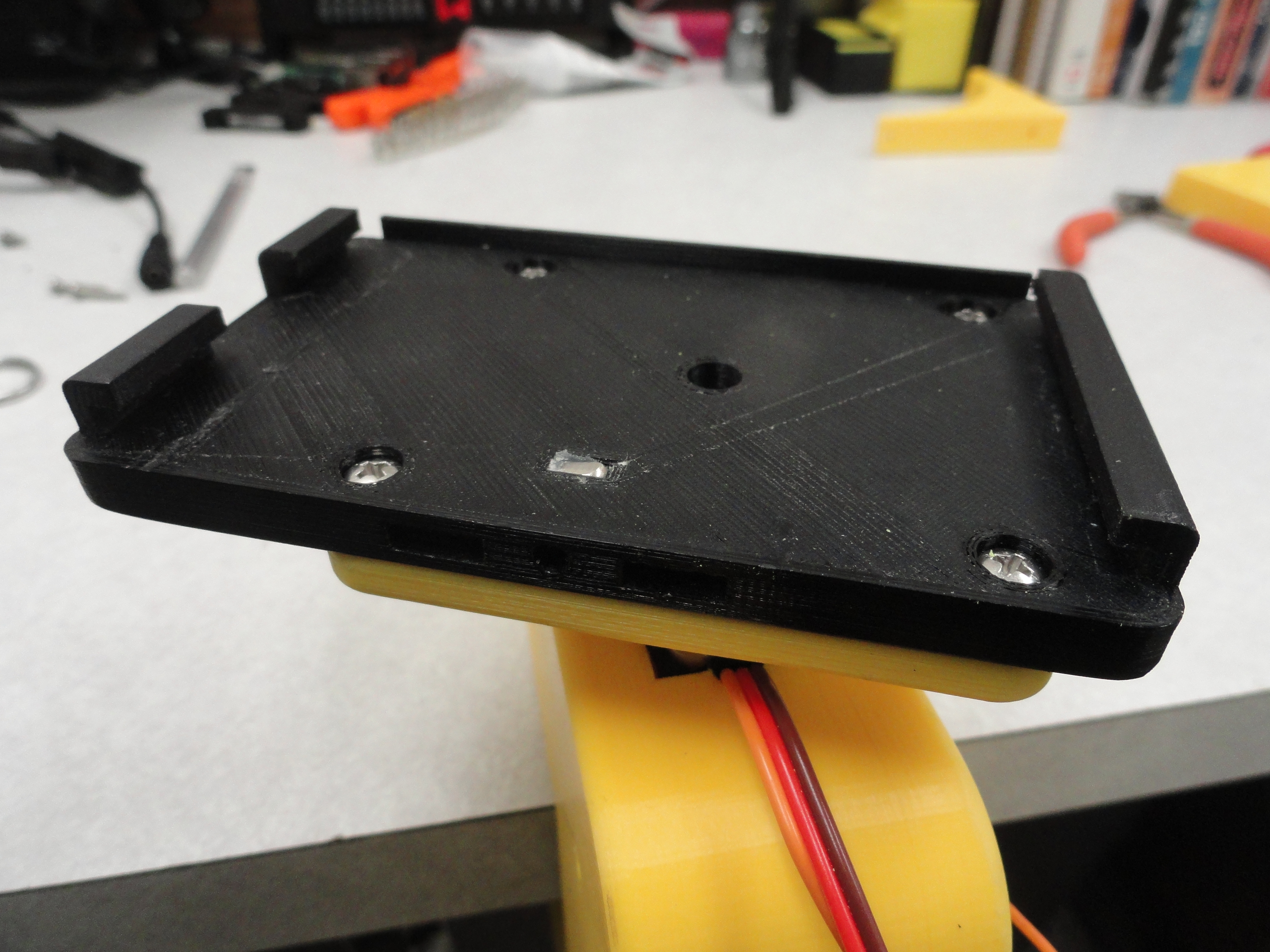
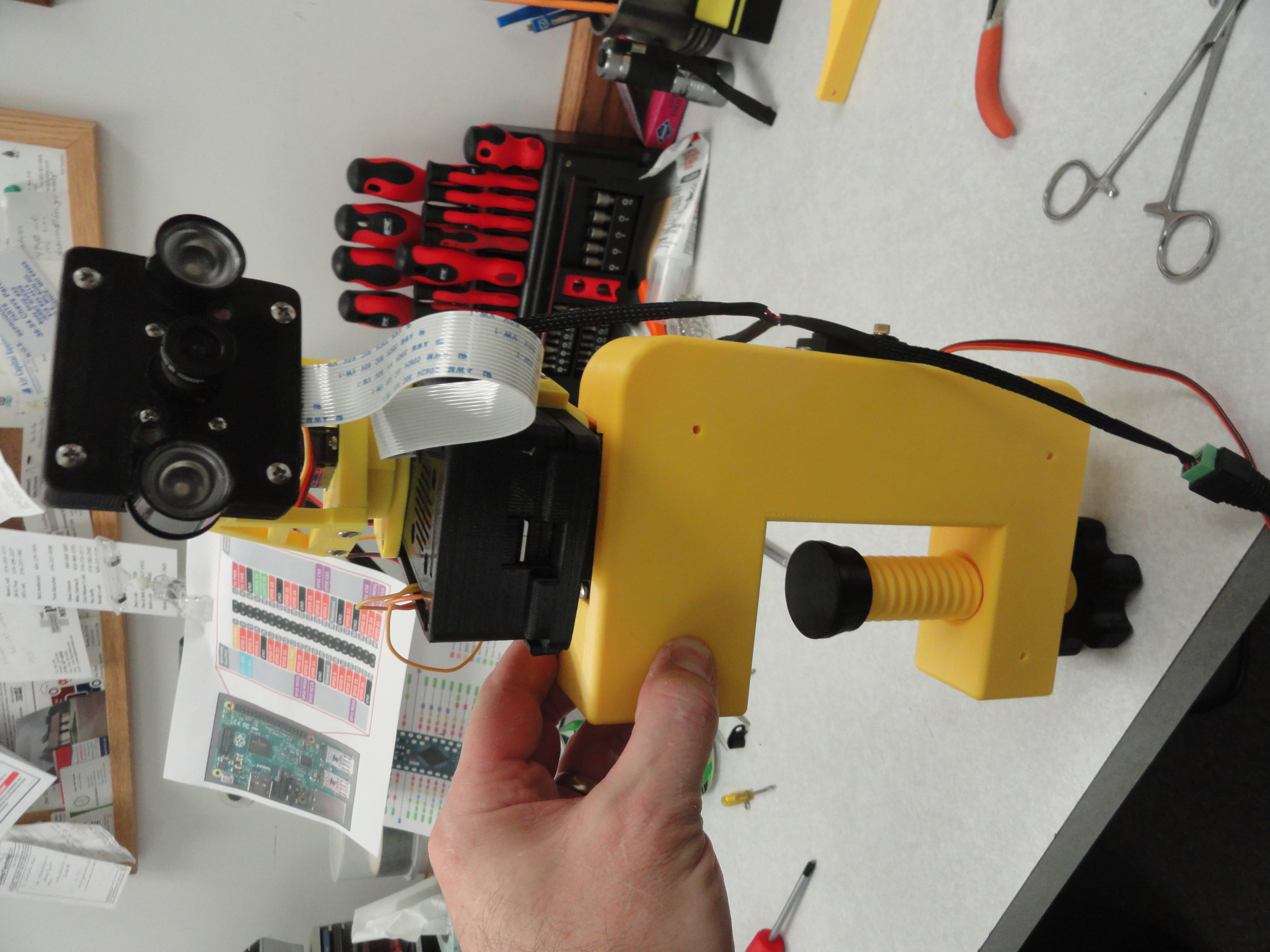
The Receiver is made to allow you to screw it directly down to the servo through the Propeller assembly. Before just putting it down and screwing it down, you need to be sure the servo is properly centered. Push the receiver down without screwing it down, notice its position and rotate the receiver carefully from one end to the other end of its travel. Notice the Receiver is not pointing in the correct direction when in the center of its travel. Use the C-Clamp's orientation to set it up so the center of the Receiver travel is aligned with the front to back axis of the C-Clamp. Lift the Receiver up and place it back down in the correct location. Tighten the center hold-down screw (3mm x 8mm) when you have decided everything is balanced. Tighten securely.
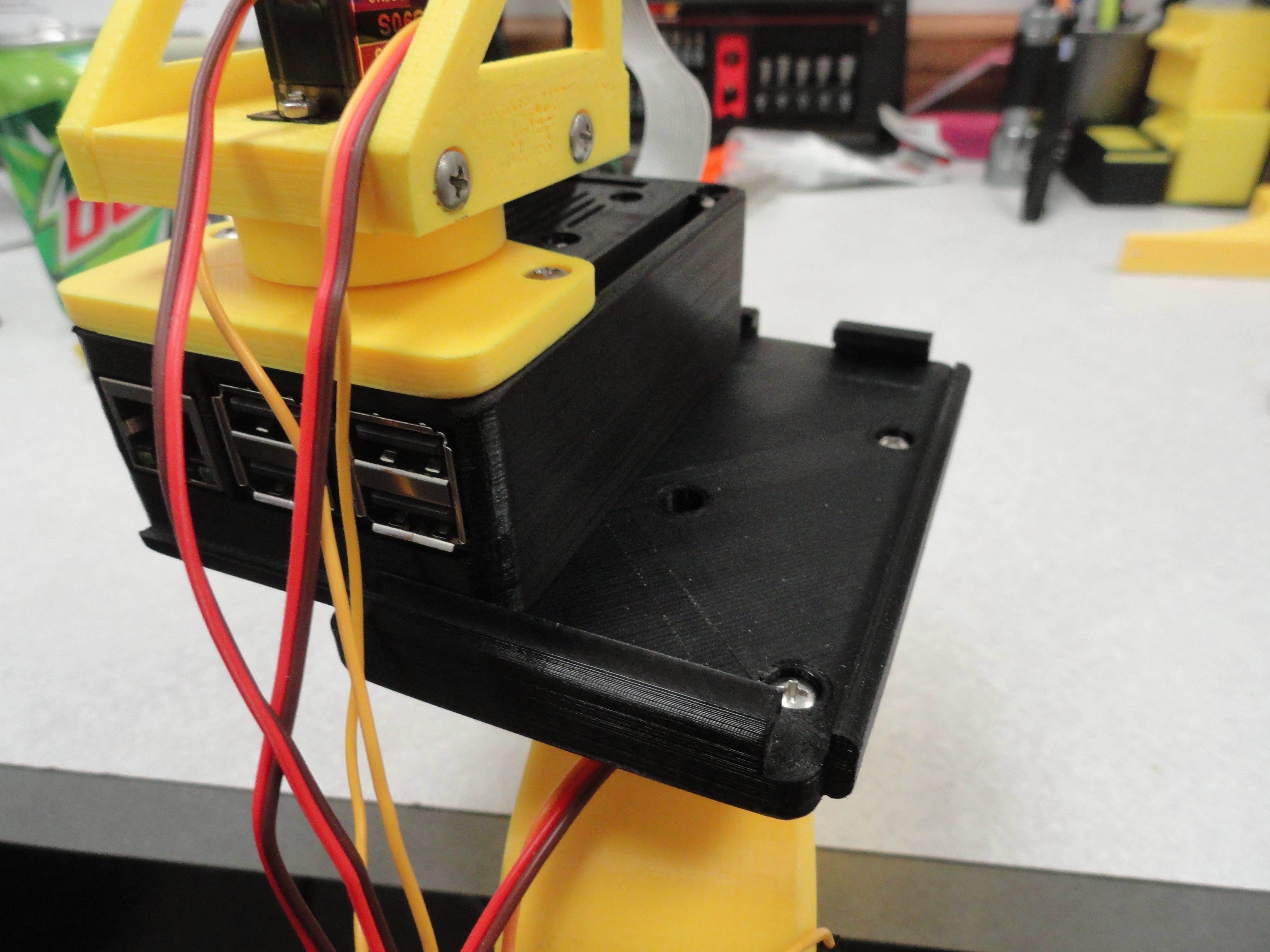
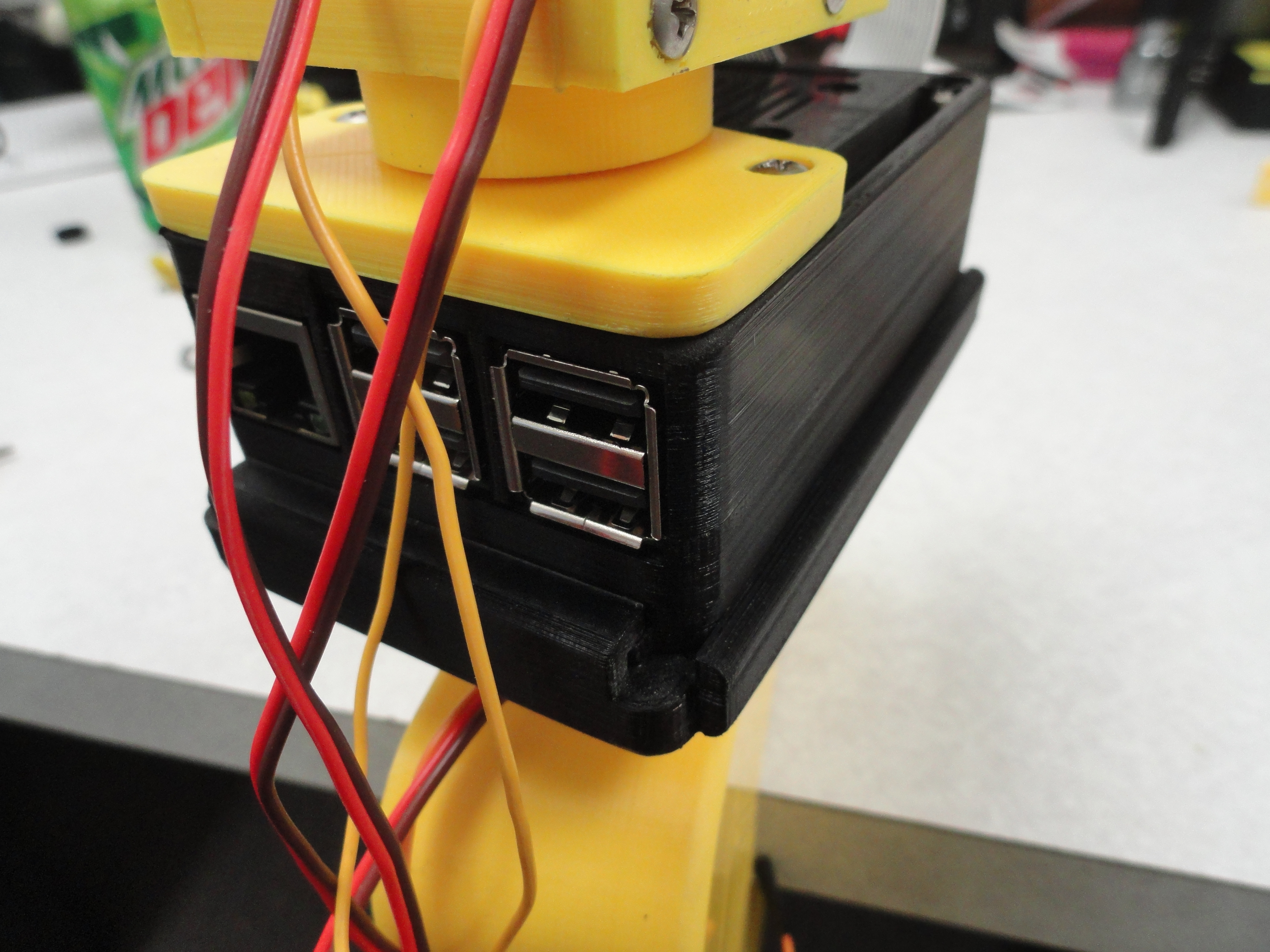
Slide the Pi into the slots observing the correct front/back orientation. You can tell by looking at the MicroSD Card slot. There is a gap for that. Once its in securely, lock it down with the small Lockdown Part with the screw in the center. It will slide right into place with the highest part UP. This uses a square nut in a recess and uses a 3mm x 20mm screw. Now your Pi should be very secure with no wobble. When you want to use the other Large Servo on the other Axis, this is how you move your Pi.
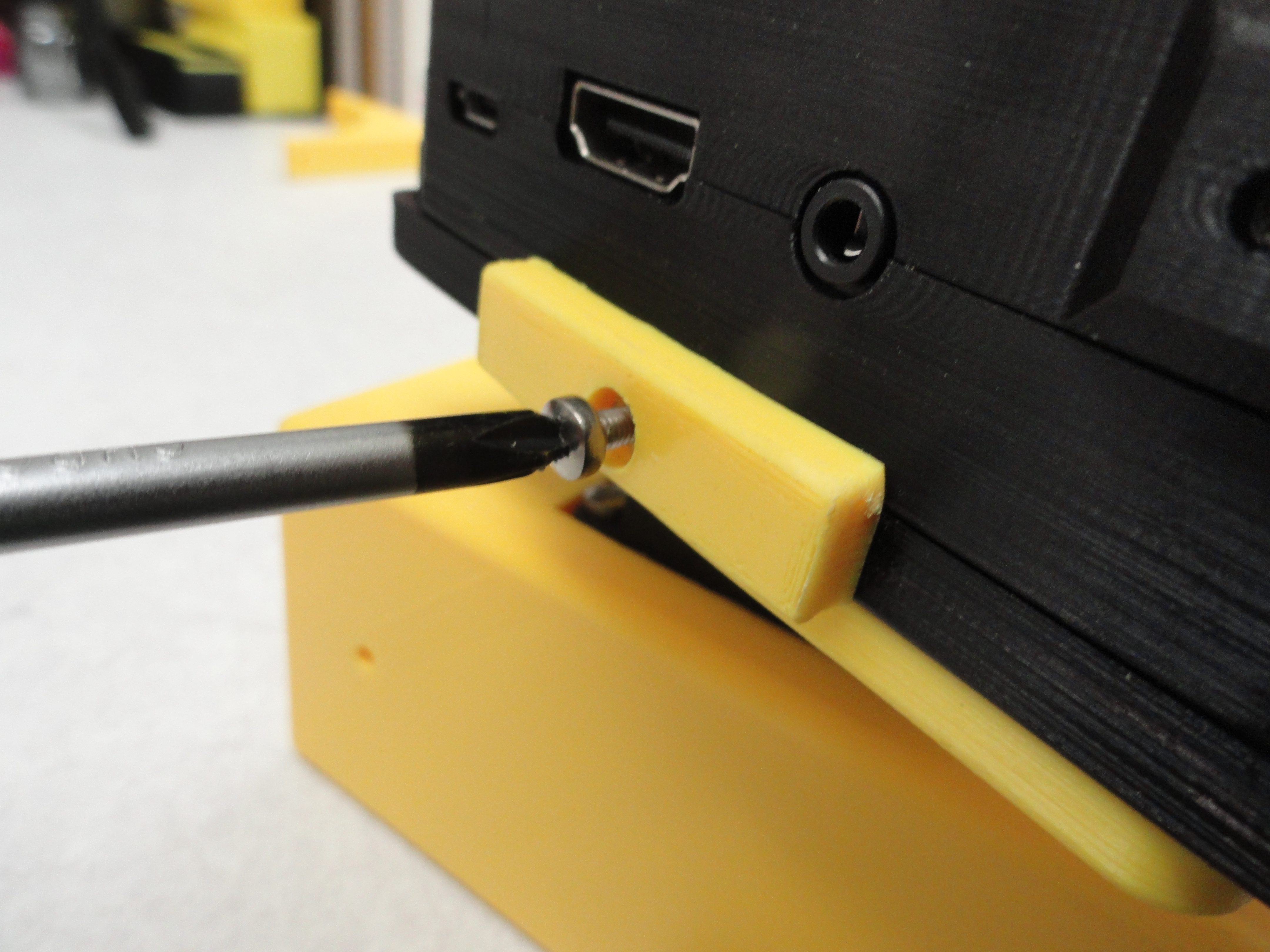
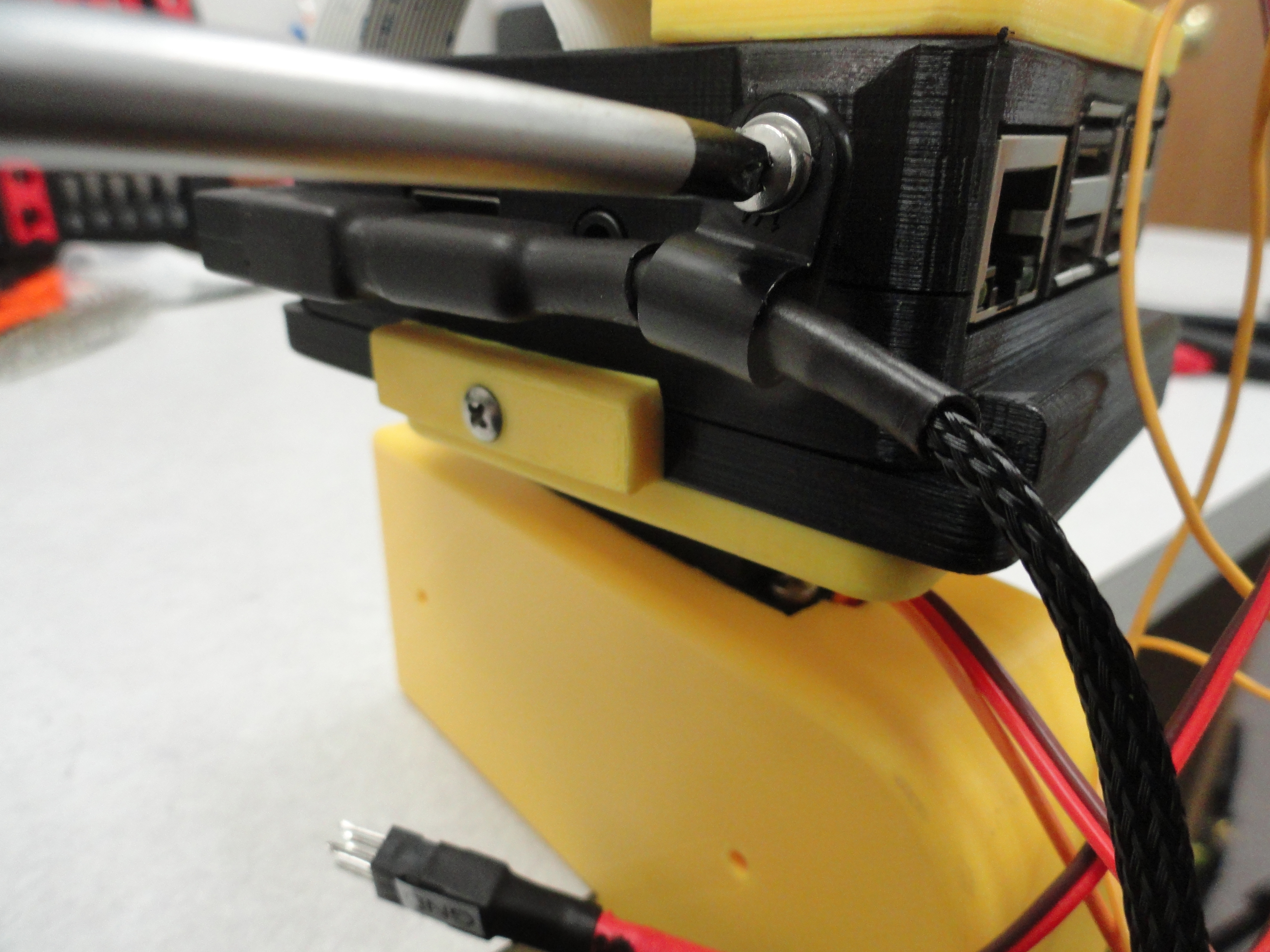
The Pi Case is equipped with a flange that allows for a cable strap to hold the wiring harness securely to the side of the Case. It uses an embedded hex nut and a 3mm x 6mm screw. Do not overtighten. The hex screw will easily turn inside the case, so take it very easy. This is a prototype. I will fix all of these issues with time.
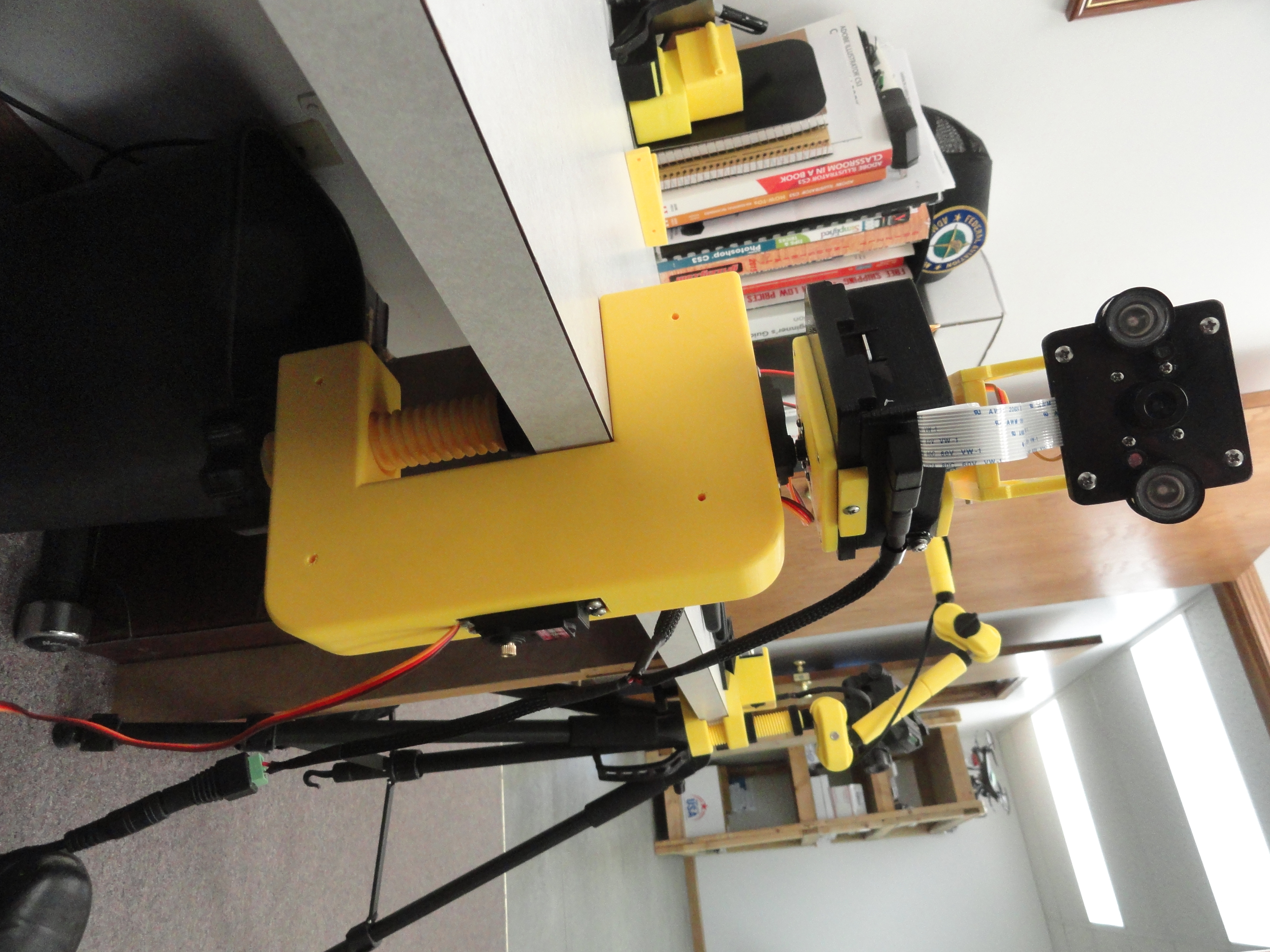
If you opted for the table top clamp, this is what it should look like. The 1 Inch Acme screw will secure the C-Clamp to any surface with a ledge. The top of a Door, the side of a Crib, wherever you choose. This was the most difficult part of the project so far, deciding how to mount it.
To orient the Pi Cam on the other Axis and use the other Large Servo, simply remove the Receiver lockdown, unscrew the center servo hold-down screw and move it over to the other axis. I have provided four (only two are shown) brackets for stabilizing the C-Clamp on a table or flat surface. It also doubles as the wall mount! The screws are 3mm x 50mm using 3mm hex nuts. Everything fits together perfectly even if it is a challenge. With one set of these brackets on, you can still mount it on the top of a door if you wish. (nobody looks there!)
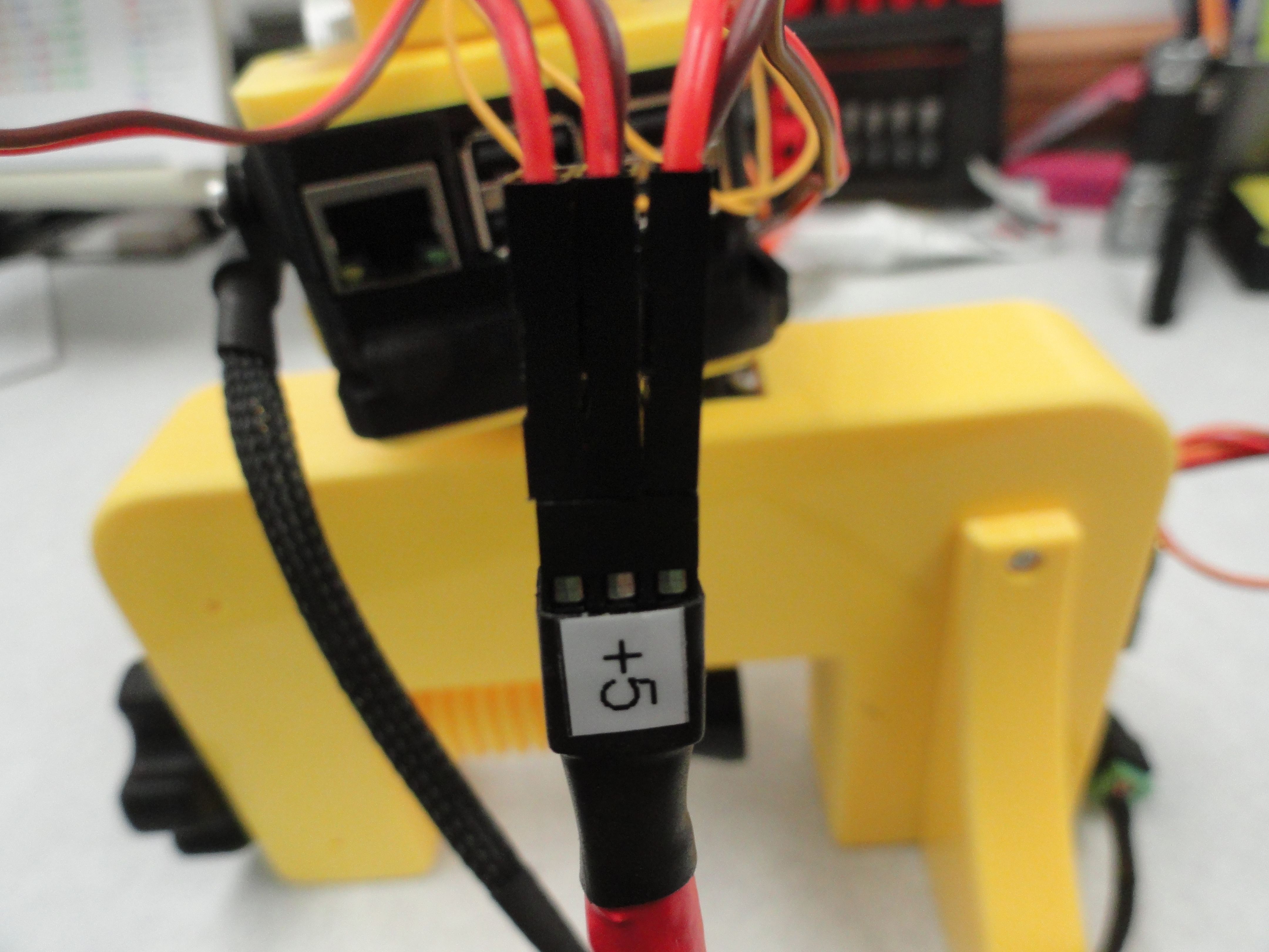
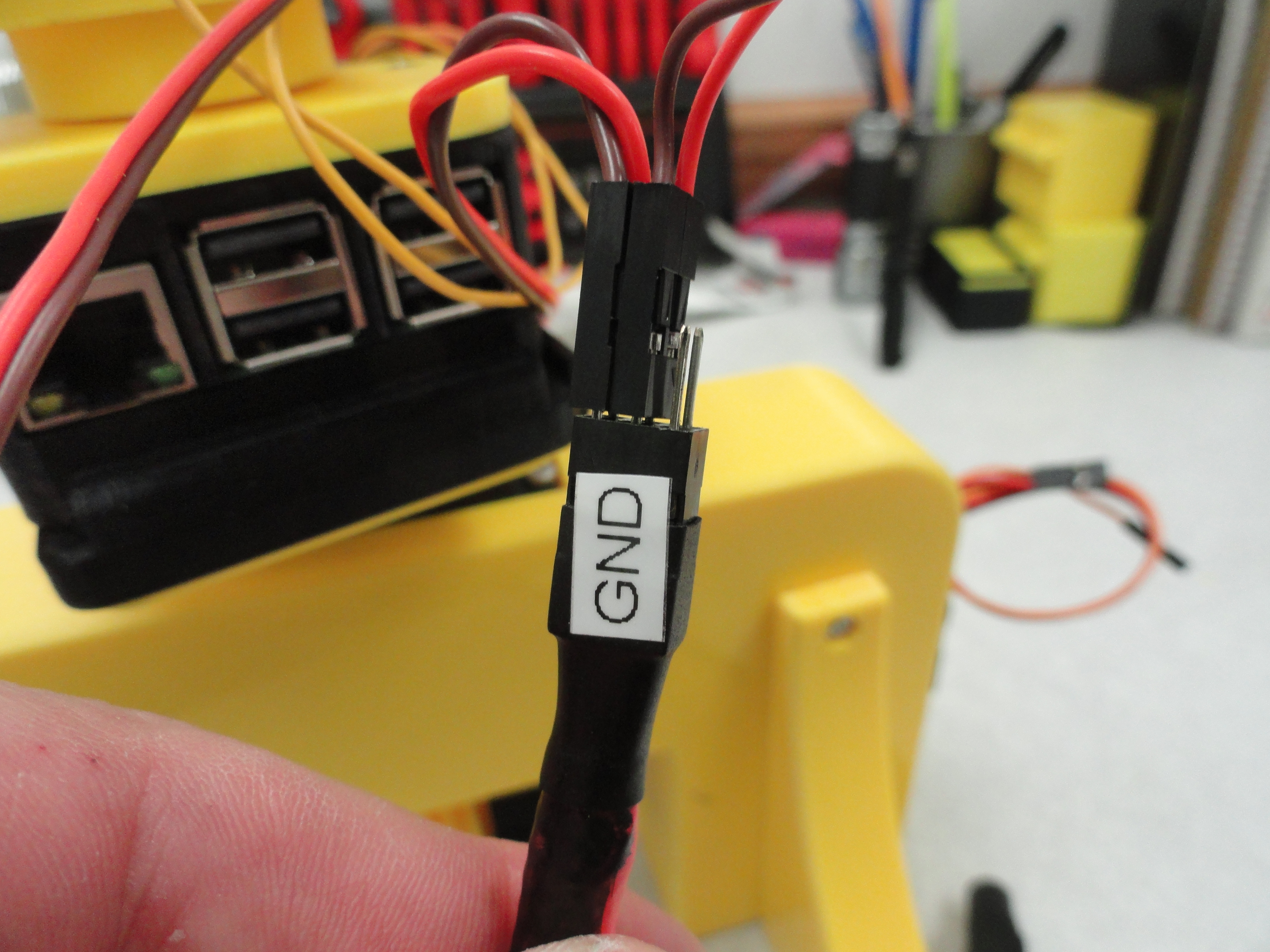
Wiring it isn't too terrible. Be sure to observe the power wires orientation for each servo. The 6 pin connector has 3 wires on one side that are +5 volts, the other side is Ground. Red to Power, Brown to Ground. To wire the servo's sense wires, I used Pin 12 (GPIO 18) for the Large Pan Servo, Pin 16 (GPIO 23) for the small Pan Servo, and Pin 18 (GPIO 24) for the Tilt Servo. This is how the Program is set up as well. This should work right out of the box without a hitch, however let me know if there are any problems I can solve from the other side of the world!
The Software
I find Raspbian to be the most responsive and best supported OS for the Raspberry Pi, so we will go with that. I also found a new friend Richard Hirst in trying to get Servo's to work with the Raspberry Pi. Richard is the maker of ServoBlaster and he has a new version out that works with the Raspberry Pi 3. I like ServoBlaster for a few reasons. First, it's dead easy to use and second and most importantly, ServoBlaster has two modes of operation. You can use regular PWM to move the Servo's or PCM. With PCM, there will be no interference with the Sound Output on the Pi. The good news is, they both do the same great quality of physical work, so there is no penalty for PCM. Get your very own copy of ServoBlaster at Richard's Github page. The documentation on the page is very good.
Next we will use the great work that is already done at eLinux.org for integration of the Raspberry Pi Camera. You can read all about how to use the camera software at RPi Cam Web Interface. This is a very complete and well done package that takes care of most of the heavy lifting. This does not take advantage of some of the great features that Richard and I collaborated on, so to get OUR version of this software, which enables threee servos, microphone, and allows for better control, go to Richards Github page and download the lastest from here: RPi Cam Web Interface. This is a fully up-to-date package and it is still in progress, so be assured, it IS being worked on.
The Software Step-By-Step
Install Raspbian Lite on your Pi. In Windows, format the MicroSD Card using SDFormatter, image the MicroSD Card using Win32DiskImager.
With a monitor connected to HDMI port on the Pi and a Keyboard either hard wired or USB, enter pi/raspberry (login) then type:
sudo raspi-config
To set up for wireless LAN, Select Network Options. Change The Hostname to whatever you wish that is descriptive of the task this Pi will be performing. Choose Wi-fi. Enter your Network's SSID and Password from your wireless router.
Choose and properly fill out all Localization Options, then go to Interfacing Options and Enable the Camera and SSH. SSH is how you will be talking to your Pi via PuTTY. Lastly, Go to Advanced Options and choose Expand Filesystem. Select Finish to get out of Raspi-Config.
To get your Raspbian OS up to date, do the following:
sudo apt-get update
sudo apt-get dist-upgrade
Now we can install the PiCam Software.
To start with, we need Git. This enables us to use GitHubs downloads. To install:
sudo apt-get install git
Next we need to get the PiCam software:
sudo git clone https://github.com/richardghirst/RPi_Cam_Web_Interface
Once you have the program, install it:
cd RPi_Cam_Web_Interface
then:
sudo ./install.sh
A screen appears after install that allows you to configure the PiCams options. For now this is basically just informational. Choose OK to begin the Installation.
6 separate scripts are provided to do separate installation and maintenance functions.
The scripts are:
install.sh main installation as used above.
update.sh check for updates and then run main installation.
start.sh starts the software. If already running it restarts.
stop.sh stops the software.
remove.sh removes the software.
debug.sh is same as start but allows raspimjpeg output to console for debugging.
To run these scripts make sure you are in the RPi_Cam_Web_Interface folder then precede the script with a sudo ./
E.g. To update an existing installation ./update.sh
E.g. To start the camera software ./start.sh
E.g. To stop the camera software ./stop.sh
The main installation always does the same thing to simplify its logic. It gathers all user parameters first in one combined dialog and then always applies
the parameters as it goes through the process. Autostart should be yes if you want this software to start automatically when raspberry boots up. jpglink
should normally be no. Change it to yes if you have external software that needs direct access to the cam.jpg image file.
A phpversion parameter provides for a choice on which php version to use (5 or 7). php5 was used up until 2017-09-22. If there any difficulties using 7 or
when upgrading older systems then try using 5.
A q (quiet) parameter may be used to skip this and give an automatic install based on config.txt All parameters are always in the config.txt file, a default
version is created if one doesn't exist and is then changed just once after the initial user dialog. The installation always tries to upgrade the main software
components and then functionally goes through the configuration steps for each area like apache, motion start up.
After the setup finishes it offers to start the camera system. It will also start on a reboot if autostart was configured.
Install Samba. This will allow us to move files from our Windows machine to the Pi. It will enable us to manipulate video files as well. It's just a good idea to do this.
Lets make a Downloads Directoy to put newly downloaded files such as Samba in:
cd /home/pi/
mkdir Downloads
cd /home/pi/Downloads
sudo wget https://download.samba.org/pub/samba/stable/samba-4.8.1.tar.gz
Note: Substitute the latest filename. The above is the example from the latest release as of this writing. Now we need to unzip the file: (Don't forget to sub the latest filename!)
sudo tar -xvf samba-4.8.1.tar.gz
For the following steps we need to be in that directory so:
cd /home/pi/Downloads/samba-4.8.1
Once it's downloaded and unzipped into your Pi, we have some Dependencies we need to take care of:
sudo apt-get install libacl1-dev gnutls-dev python-dev libldap2-dev libpam0g-dev libssl-dev
Those are the Dependency Files that will error if you do the following before the previous step. Next we need to configure:
sudo ./configure <-- takes about (5m39.736s) <-- Don't worry about all of the "not found" entries.
After ./configure you need to make the file. The below command cuts the make time in about a third. -j 4 tells it to make using all four of the Raspberry Pi's processor cores.
sudo make -j 4 <-- takes about (19m29.890s)
then:
sudo make install <-- takes about (15m39.509s)
The next thing we need to do is to set the Path parameters permanently:
sudo nano /etc/profile
add to the very bottom of the file:
export PATH=/usr/local/samba/bin/:/usr/local/samba/sbin/:$PATH
To make Samba work automatically from startup, we need to create a script. Put this script in /etc.init.d/ and name it samba
sudo nano -w /etc/init.d/samba
place the following script in the file:
Once the script is safely in the file, we need to tell the Pi we want that script to be executable: sudo chmod +x /etc/init.d/samba Next we need to update the system to allow the script to run at startup: sudo update-rc.d samba defaults sudo reboot Now let's talk a little about the Samba Main Configuration file located in /usr/local/samba/etc/smb.conf. Here is a typical working smb.conf file. To use the one that came with the package, do a sudo find -name smb.conf from the top directory. This config enables a share to be available in Windows 10. To edit this file: sudo nano /usr/local/samba/etc/smb.conf NOTE: if the nano window is blank, copy the below script into your nano window or get one that comes with the package via sudo find -name smb.conf as mentioned earlier. This is the configuration file for your Shares. If you do this one exactly as it is below, you will get one Share named RaspiShare with the directories allowed by the user Pi. If you wish to see all directories on the Pi, near the end of the file, change Path (under RaspiShare) to just a forward slash.
Entire Article for Samba can be found at Our PiSamba PageInstalling ServoBlaster
The latest and greatest ServoBlaster is at Richard's Github Page:
You can copy the ServoBlaster Directory with all files via Samba to:
home/pi/Downloads
or you can go direct to the Pi by using this command while in home/pi/Downloads on the Pi:
git clone https://github.com/richardghirst/PiBits.git
Once its successfully in the Downloads directory,
cd ServoBlaster/user
Once in home/pi/Downloads/ServoBlaster/user:
sudo make install
sudo ./servod
To get it to load automatically, copy the file: ServoBlaster/user/init-script to /etc/init.d/ and rename the file from init-script to servoblaster. From the /user directory:
sudo cp init-script /etc/init.d/servoblaster
then from the /etc/init.d directory:
sudo chmod 755 servoblaster
Note: To remove ServoBlaster from your system...
sudo make uninstall from /home/pi/Downloads/ServoBlaster/user
Richard has really good instructions on how to make ServoBlaster do its thing on his GitHub page here:
https://github.com/richardghirst/PiBits/tree/master/ServoBlaster
The Web Interface
Now we need to set up the Web Interface. The main software is already in the package we installed earlier (RPi_Cam_Web_Interface) but with Richard's help we are going to make it better. First, you can see your camera works over the local area network by typing YOUR.IP.ADDRESS.HERE/html. This is not your Internet Provider's address that was assigned to you, it's the internal LAN IP address. For me it's 192.168.1.114/html.
With your Servo's working with the Pi, we can now get them to work over the LAN. To do that, change the file in /var/www/html from servo_off to servo_on
as follows:
sudo mv /var/www/html/servo_off /var/www/html/servo_on
There is a script called pipan.php in /var/www/html. This script is important in incorporating our servos. It will allow us to change which Servo Numbers
we assigned to Pan and Tilt as well as the Servo movement angles. Most of us think in terms of a Servo Span being between 0 and 180, but the way that was chosen
is to use between 50 and 250. This is a more accurate way to represent Servo Spans.
Addressing pipan.php
Let's look over this script:
sudo nano /var/www/html/pipan.php
There is only a few lines we need to address to get our Servo's up and running correctly, but you may need to experiment with the numbers so you do not overdrive your servos or lose some of the span distance that is possible. The four lines below "//pipan settings" are the default max and min values and can be left alone. It's the next set of numbers we may need to play with to get the best performance out of our servos.
In pipan.php under the heading "//default servo settings" we have the first two numbers show the middle of the Servo's travel. The default is 'x' => 165, and 'y' => 165. x=pan and y=tilt if you wired your Servo's correctly. The way to change your Servo's travel to its min and max is to change the Xmax/Xmin and Ymax/Ymin numbers just below.
Before you attempt the above, the default Servo Numbers are X/Pan Axis Servo 0 and Y/Tilt Axis Servo 1. This corresponds to the GPIO Pin numbers you assigned to each Servo in the /dev/servoblaster file in ServoBlaster. If you are like me and used different GPIO pins (in my case 5 and 6) then you need to change that here in pipan.php. Locate the "switch ($action) {" section of the above pipan.php script and change to your correct numbers in the four places for 'Xplus', 'Xminus' 'Yplus' and 'Yminus'. Remember this is all about how you first wired the Servo's. Which GPIO Pins equate to which Servo's are in the Chart below.
This chart is from Richard's Github Site.Servo number GPIO number Pin in P1 header
0 4 P1-7
1 17 P1-11
2 18 P1-12
3 21/27 P1-13
4 22 P1-15
5 23 P1-16
6 24 P1-18
7 25 P1-22
[THIS IS THE PART I NEED TO FIX!]
Now to include Richard's Sliders (which are awesome by the way), do the following! These take the place of the large blue arrows and take up much less space.
What is more, the tilt slider is capable of 0-180 (normal servo action) but the Pan slider is capable of 0-360 by combining two pan servos! How cool is that?
Move control-child.php, sliders.sh and sliders from your windows machine as follows:
In your Pi,
cd .. and cd .. again
then
sudo chmod 0777 var
cd /var
sudo chmod 0777 www
cd www
sudo chmod 0777 vars
now drag and drop your three files from Windows into the Pi as follows:
move control-child.php into /var/www
move sliders.sh into /var/www
move sliders into /var/www/vars
on the Pi,
cd /var/www
chmod +x /var/www/sliders.sh
cd /var/www/vars
sudo chown www-data.www-data /var/www/vars/sliders
Now with that set up, we can control the sliders as follows. Edit this file to change the mapping of the sliders to the servos:
sudo nano sliders.sh
Change sliders.sh to reflect the proper GPIO pin. Instead of echo 0=, change to echo 5= for example.
To change the limits of the Servo's (default 50-250):
sudo nano control-child.php
Now just open up any browser on any computer in your network and enter the IP of the RPi as URL. Only the IP.