

Deve's Technical Network
1947-1955 1st Chevy Trucks
216/235/261 Engine Solutions & More
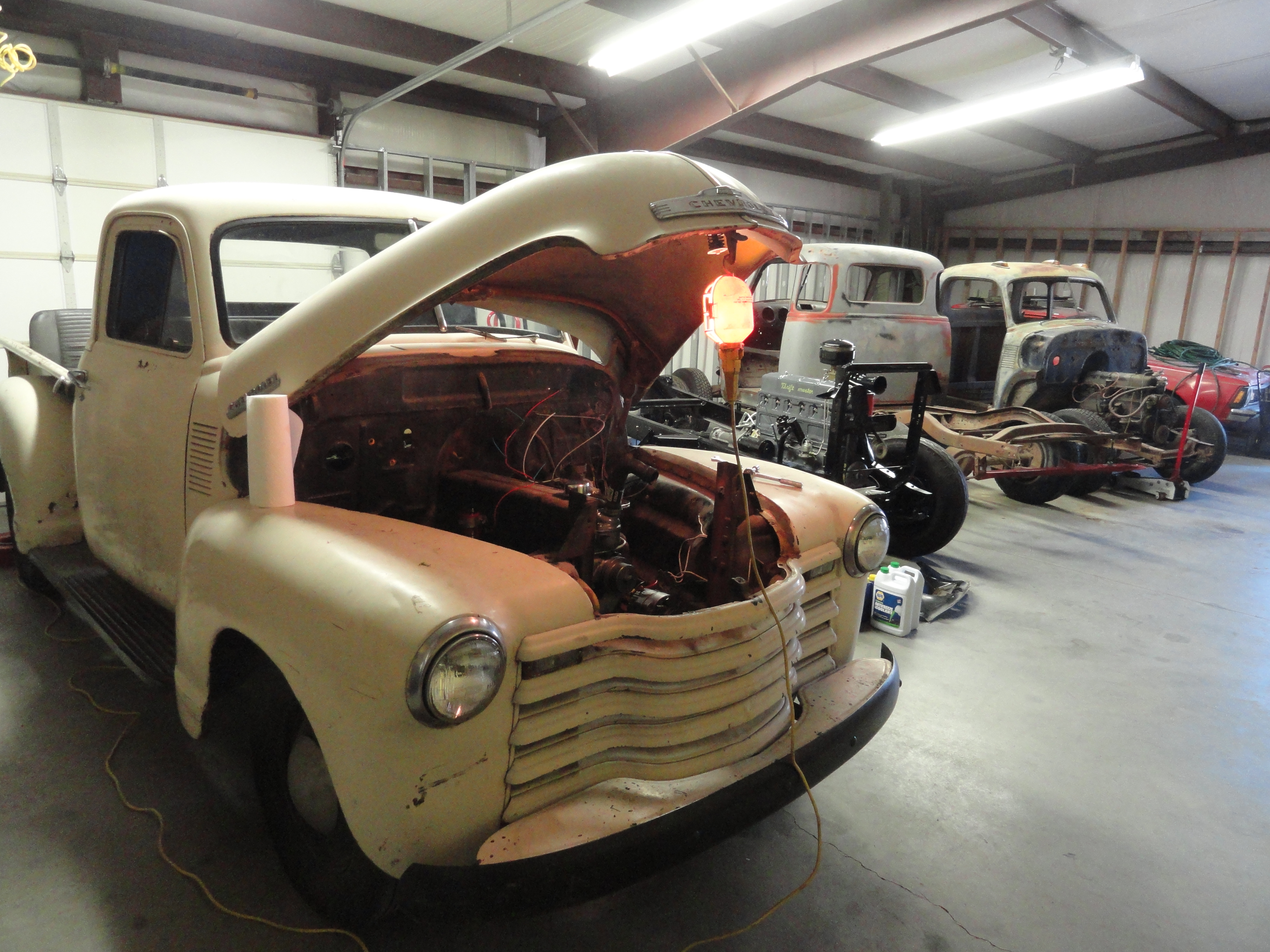
Not much changed over the years from 1947 through 1955 but there might be some small nuances between the years. This tutorial will go over all aspects of Project 1953. Project 1953 is a 1953 3100 Pickup in VERY bad condition. This truck was complete so it was a candidate for a minor restoration. Complete does not mean Serviceable however. Almost nothing on this truck was serviceable. That being the case, anything having to do with Electrical Wiring is addressed in this article. If this is too in-depth for you, that would be the reason.
We will start at the front of the truck and move towards the back to make things as sequential as possible. In our case, we do not even know what voltage headlights are in the buckets, let alone the condition of them. This is true for the condition of all of the associated electrical system parts.
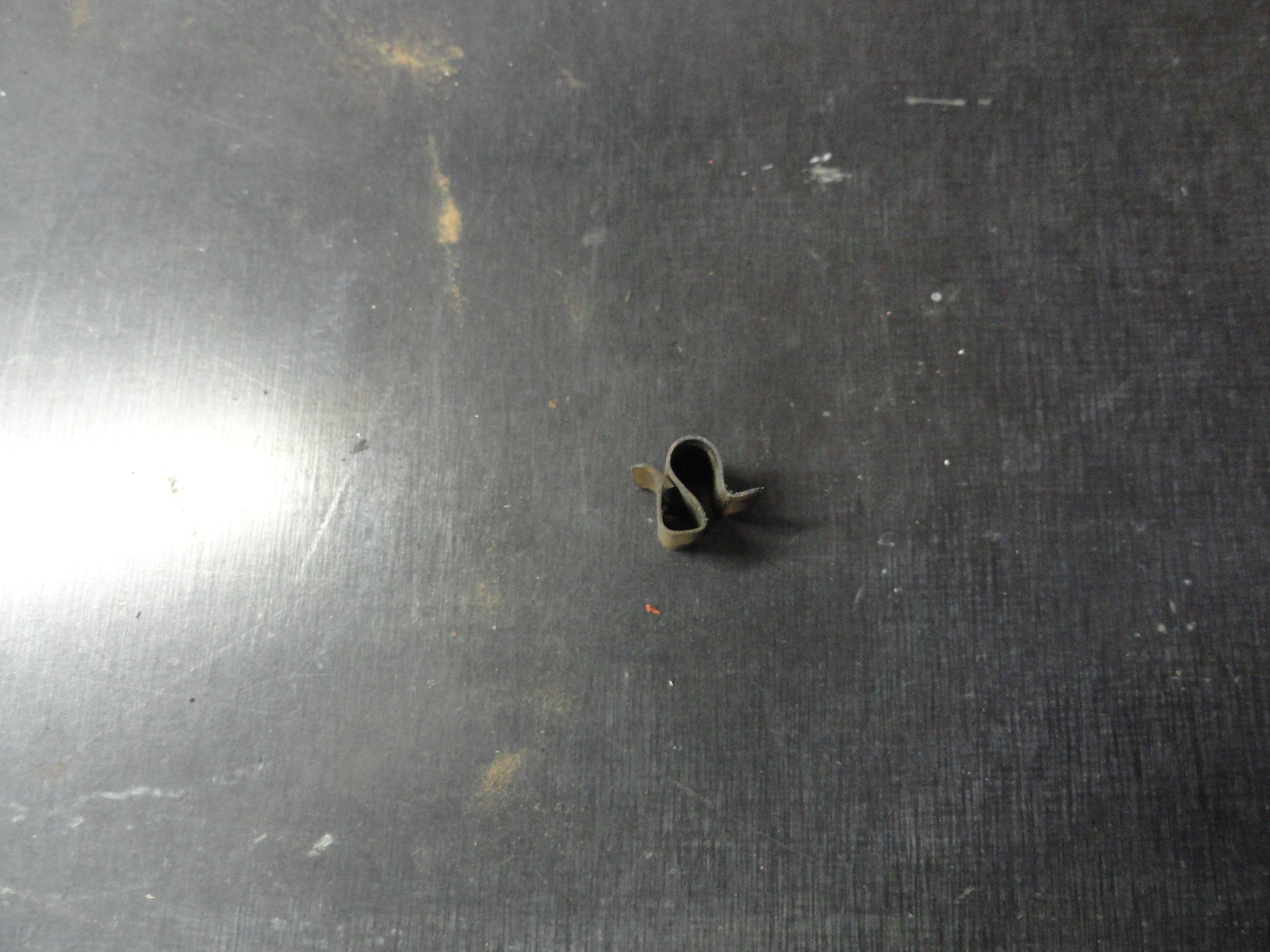
Start by removing the headlight trim piece with one Phillips screw at the bottom. Assess the condition of the seal that is inside of that trim piece. If necessary, replace the trim seal. Remove the nine #8 sheet metal screws that hold the Headlight Bucket Assembly in the fender. Since we are replacing the wiring harness, cut the wires to the headlights so you can get them out. Now is when you need to decide if you want to install new headlights at the same time as the harness. With the headlight removed, we can separate the inner bucket assembly. With a pair of needle nose pliers, pull up and outwards on the spring. Once the spring is no longer holding down the inner bucket, remove the two special adjustment screws and the special nuts from the slots they are in. Now you can cut and toss the old headlight grommet. With everything separate, assess the condition of the bucket parts.
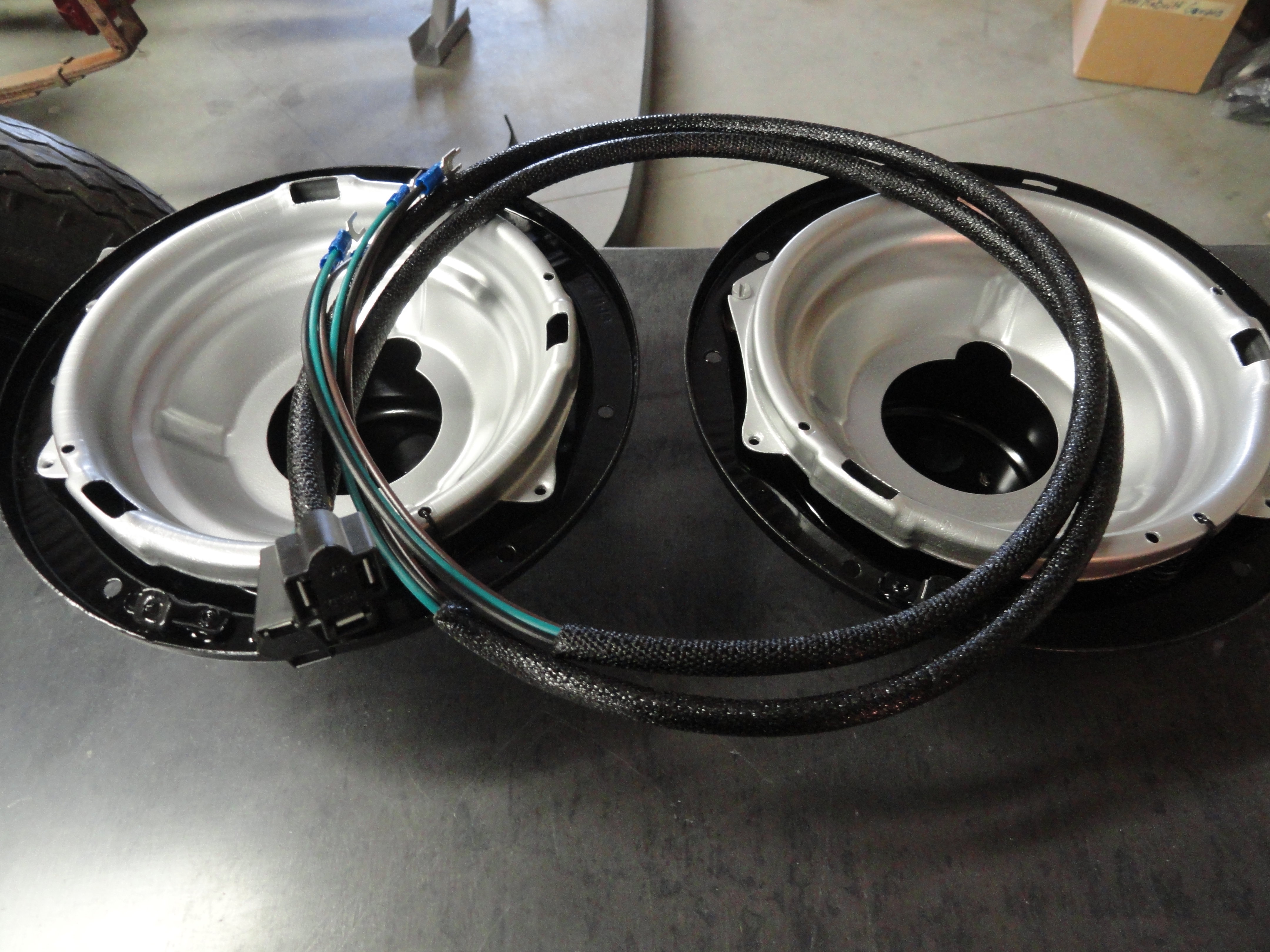
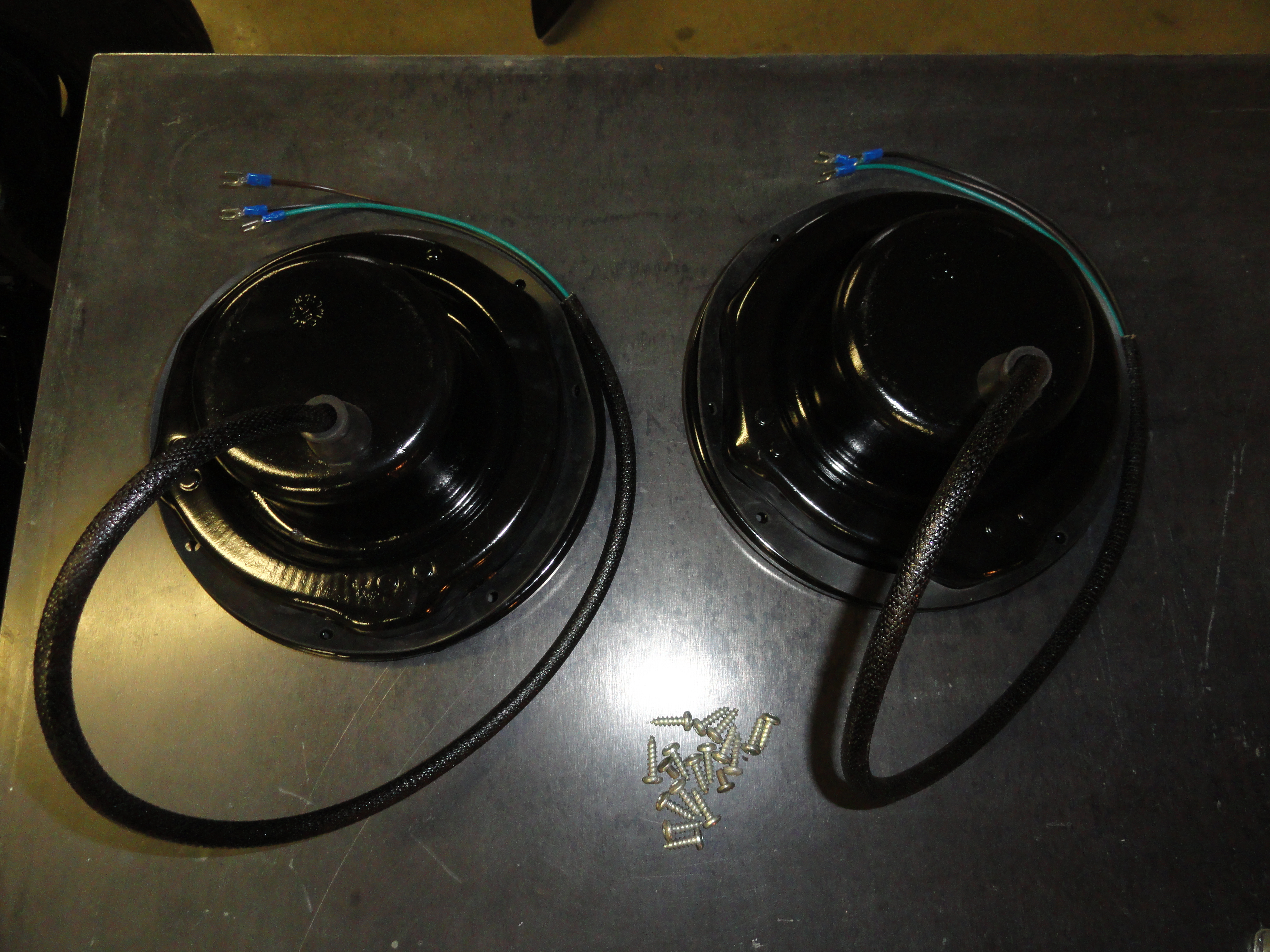
I found lots of rust and the parts were in pretty bad shape. To avoid a worse situation, I sandblast the bucket parts, apply a self etching primer and then a few coats of black paint to the outer bucket and a few coats of silver/chrome paint to the reflective area of the inner bucket. With all of the parts looking like new, I then added the headlight grommet to the back of the bucket, reinstalled the bucket parts together and inserted the buckets in their respective holes. The Harness comes with two very nice headlight harnesses for installation through the inner fender as shown.
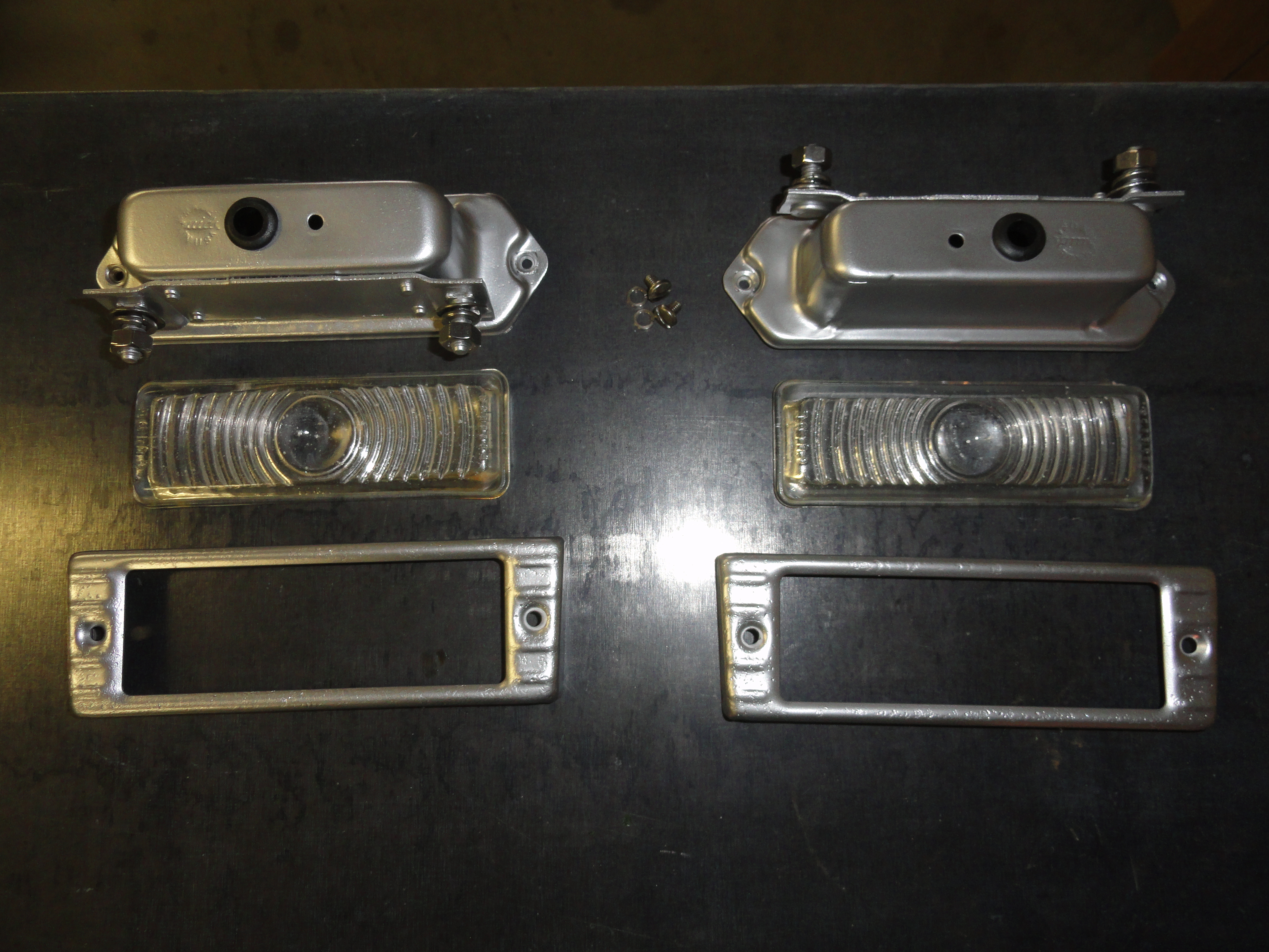
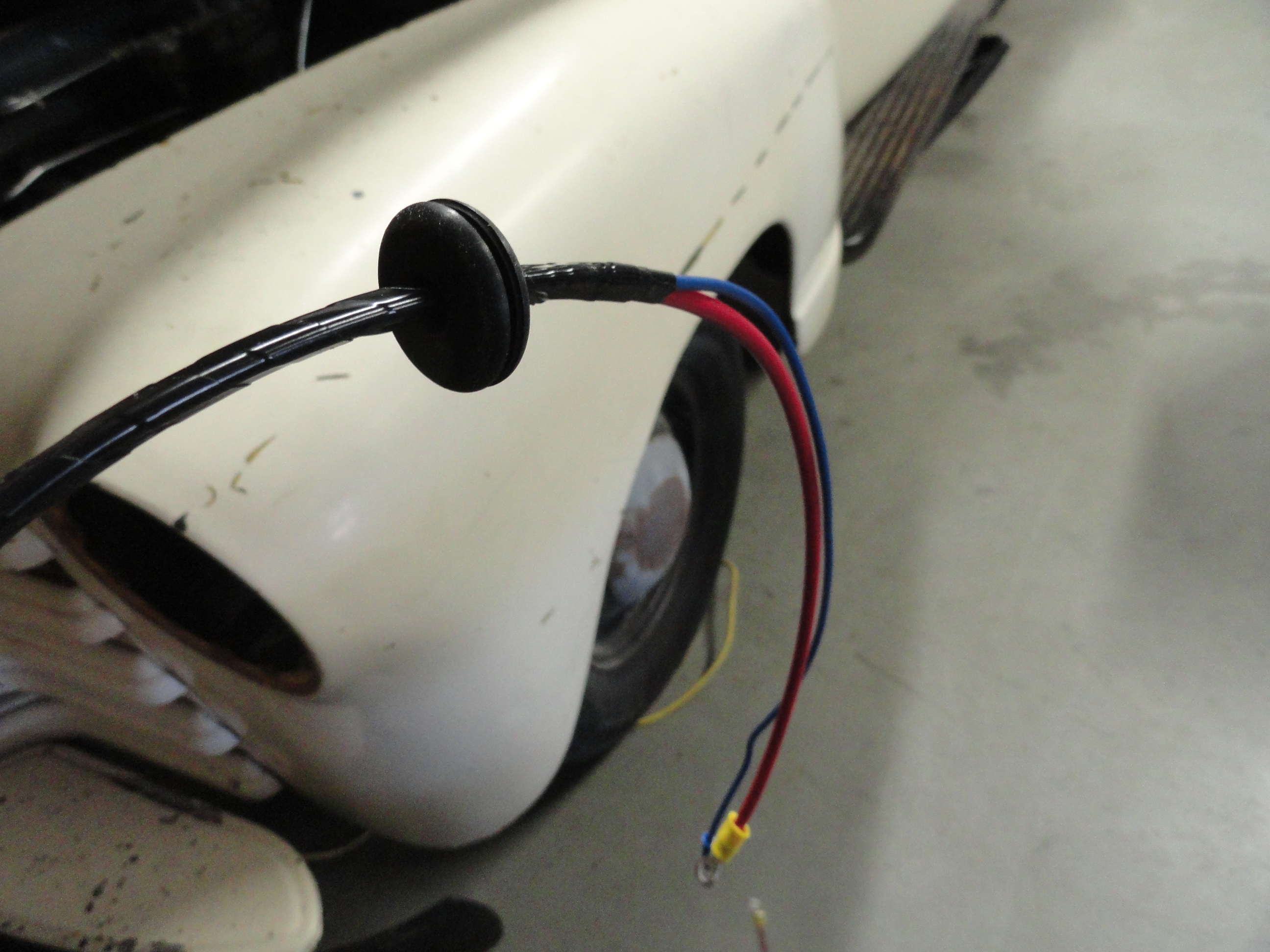
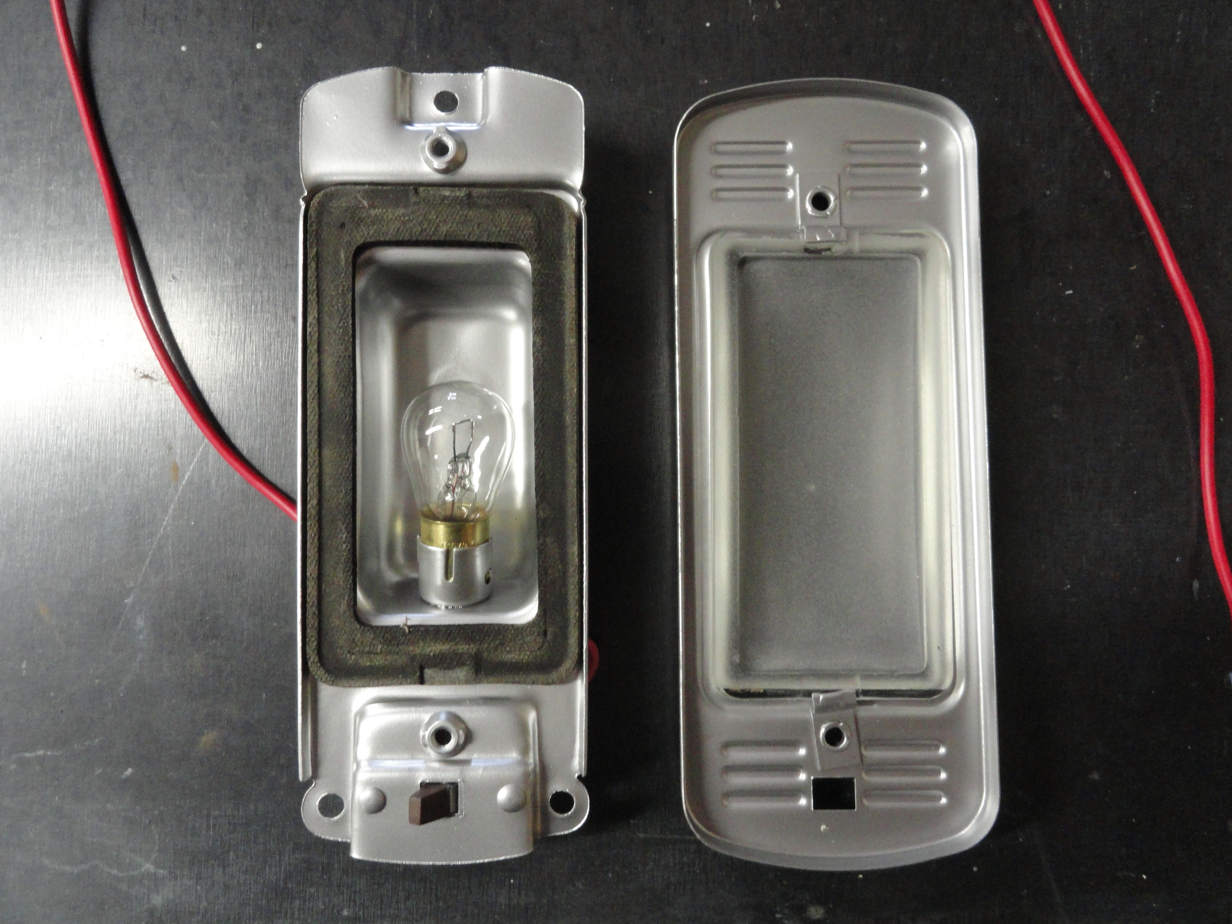
With the headlights squared away, next we will attack the Park Lights. Since we have decided to use the turn signal wiring that comes standard with our harness, we need to do a modification to the original Park Lamp Housings. The bulb socket will no longer reside inside the housing, rather, it will be mounted behind the housing. Drill out the grommet hole to 3/4" then place the new adapter sockets in the kit over the holes. You will want to mark and then drill the second mounting hole. To make the housing fit nicer upon installation, I took a small hammer and bent the new adapters mounting plate around the outside of the housing. Once it is tightened securely, I found this really easy to do without ruining anything. The new lamps have sort of a nuance that I didn't realize until I got slightly frustrated. They need to go in only one way so the pegs on the side of the bulb are offset as is the bulbs socket. If you can't get them to click into place, turn them 180 degrees! You need one 1034 lamp for each housing. This dual filament setup now allows you to use the park lamps for turn signals. How cool is that?
Reinstall the Park Lamps/Housings after sandblasting, etching primer, coats of silver/chrome paint for its reflective properties using the new gasket. Clean the glass as best you can and bolt them down. The best way to get to these wires and the wires in the new harness is to remove the top hood latch tray. This makes getting to the wires and, in my case I installed the horn inside there as well, very easy to get to. I had an old VW Bug 12v horn sitting around and decided this was the perfect place for it. I may revisit that decision in the future, but I wanted a working horn to do this document. This horn as two terminals. One is ground, the other positive 12v. I simply ran a short jumper to a mounting bolt for the ground connection since there will only be one wire in the harness devoted to the horn itself. This is normal.
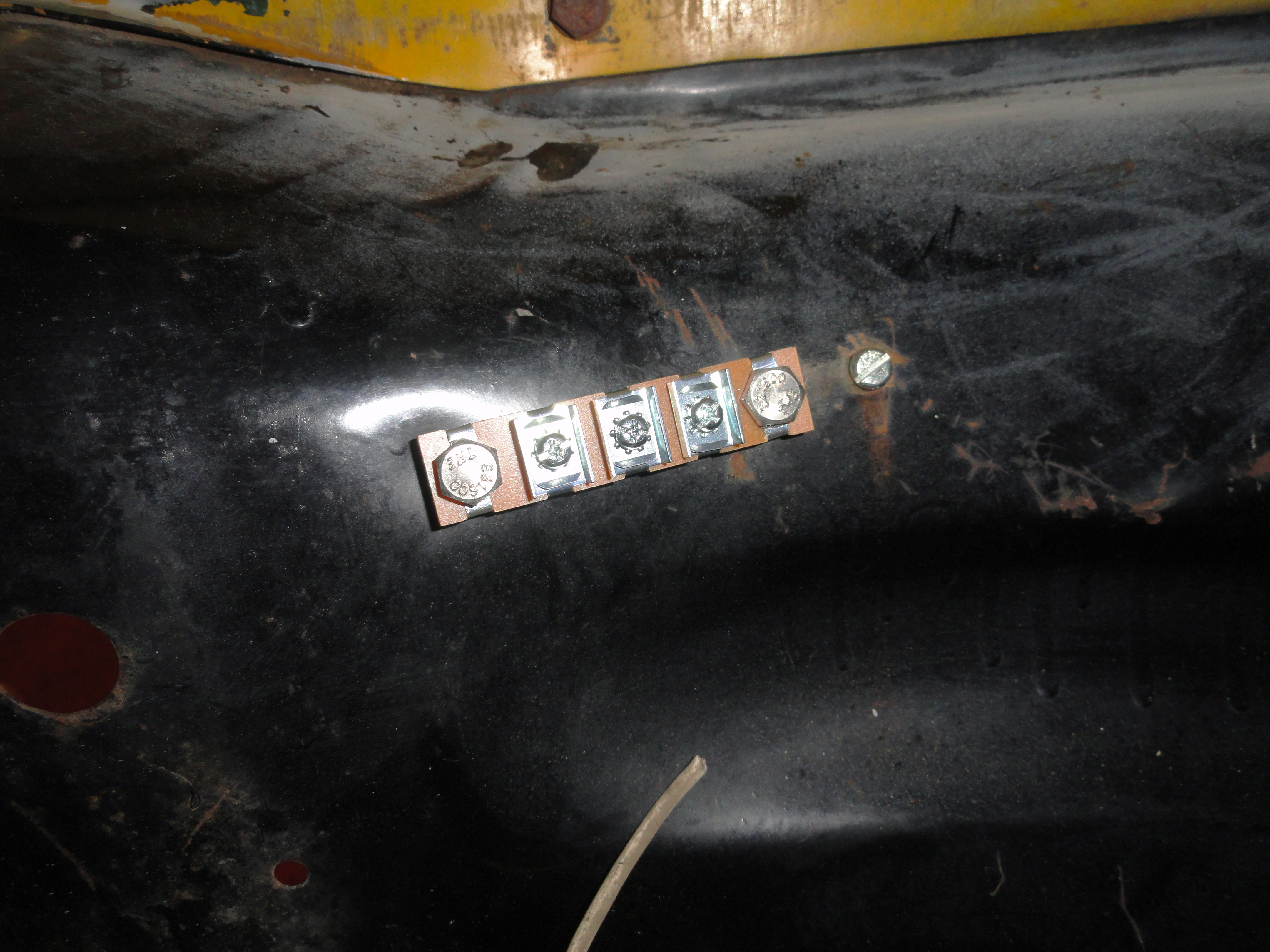
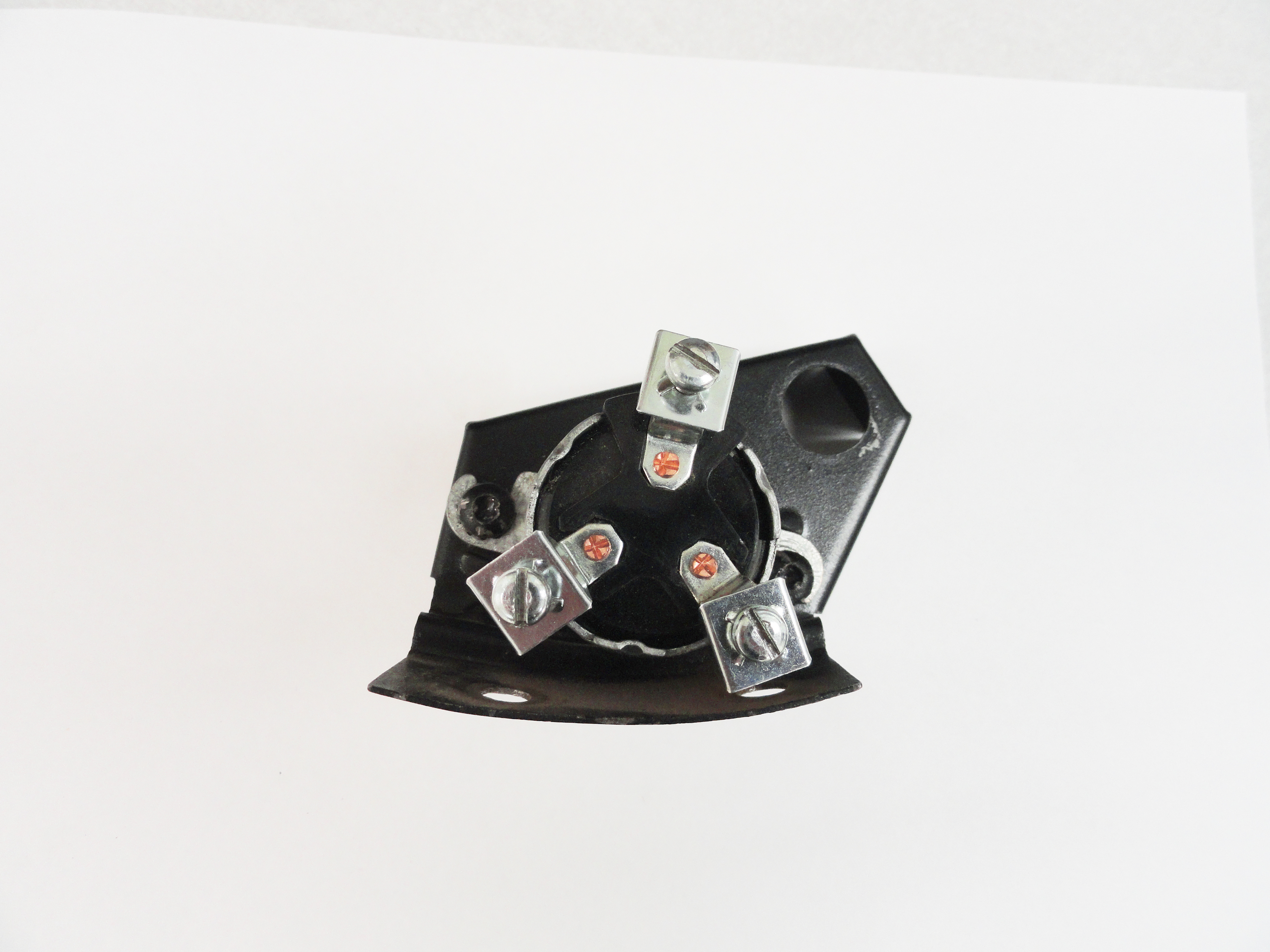
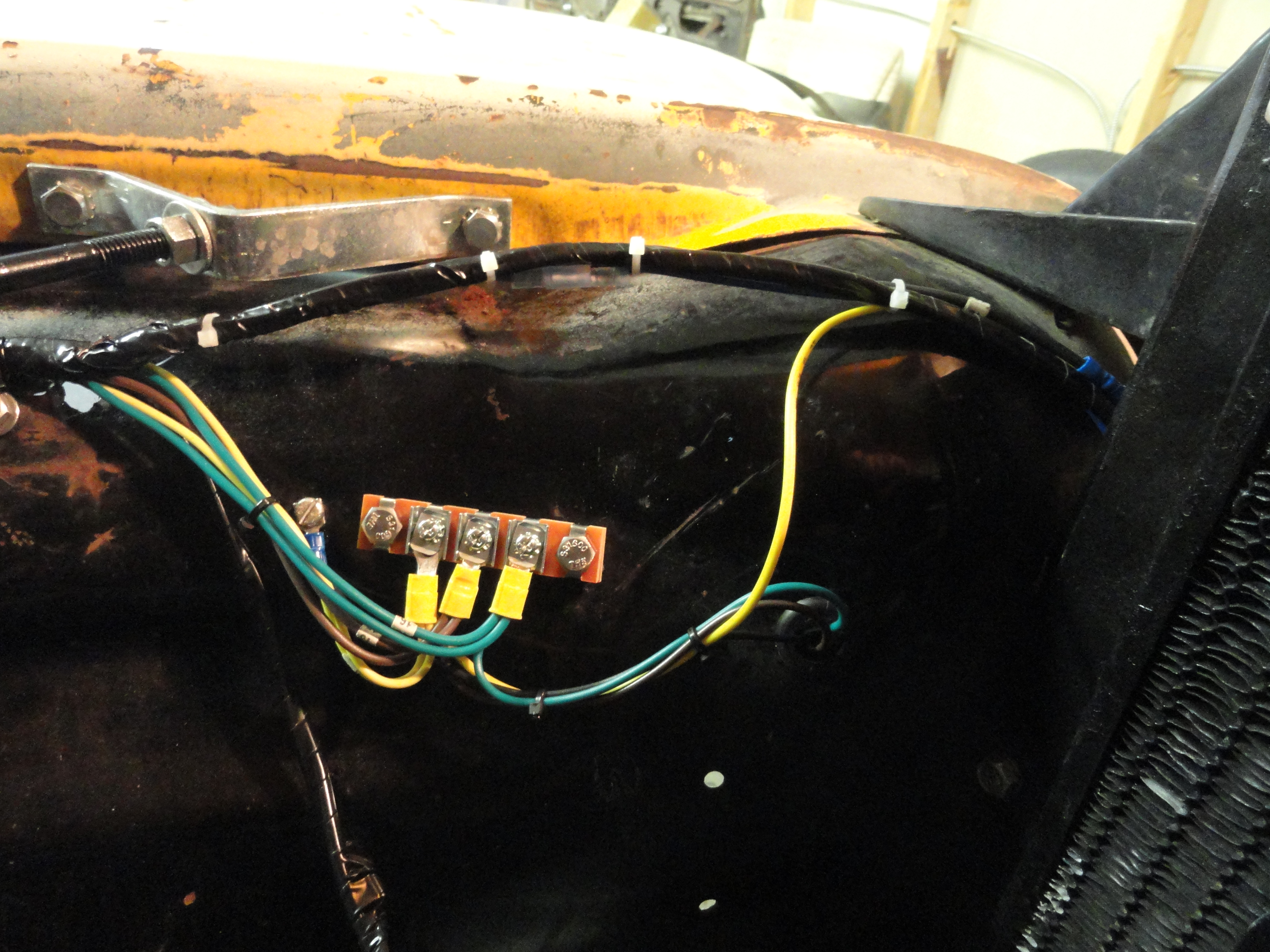
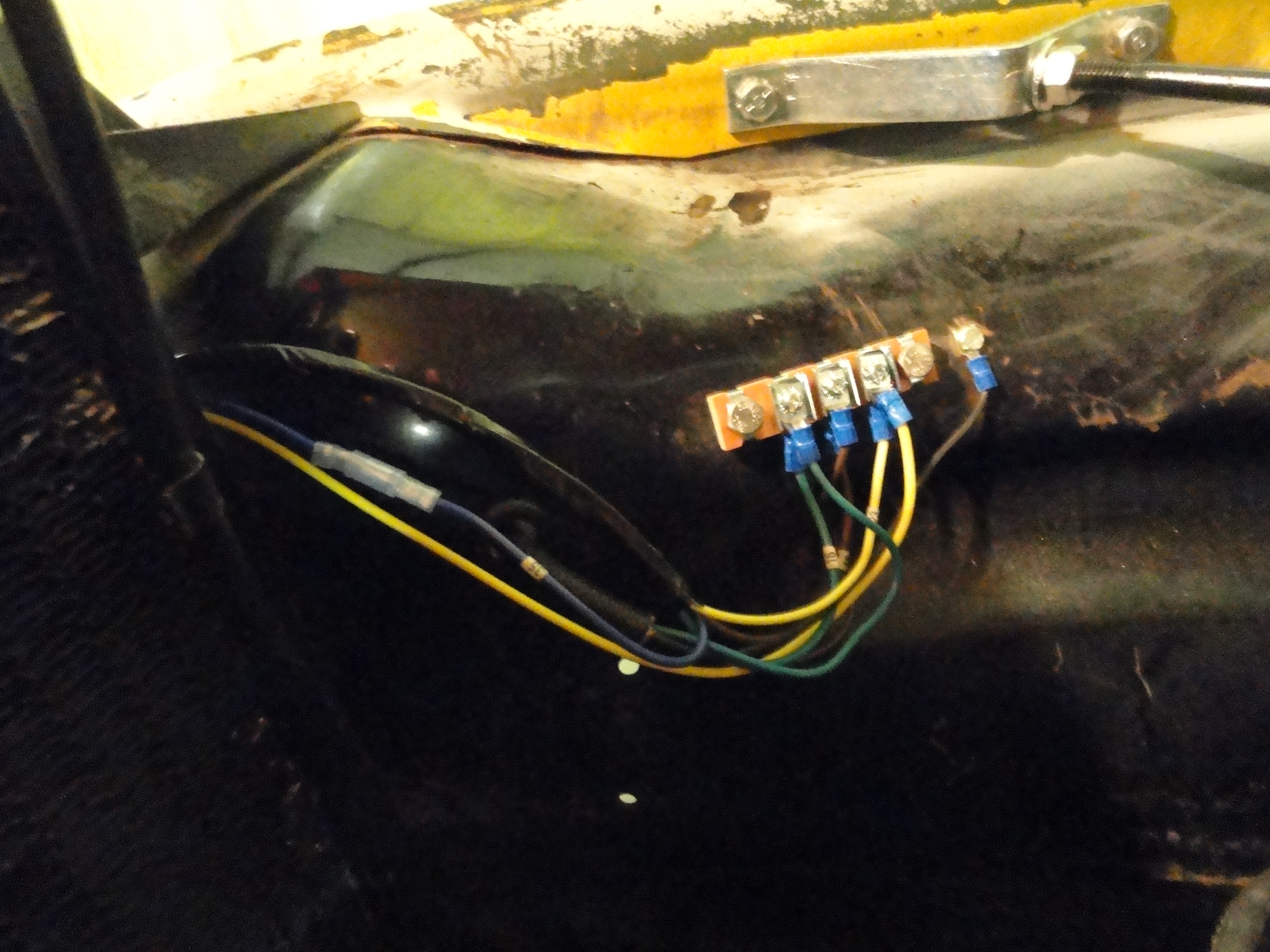
I do not trust the old terminals, in my case what was left of them, so I purchased new ones. One might be tempted to get a 4 wire terminal since the vendors sell both, but the reason this is not good is because the inner fenders have mounting holes that fit the respective terminal strip. In 1953 they used 3 terminal strips. Mount the new terminal strips using two 1/4" bolts/nuts/washers on each inner fender. I might also caution you that when it comes time to tighten down the wires to the screws on the terminals, do not gorilla them in! These terminals will strip too easily. Ask me how I know.
Install a new sheet metal screw beside the terminal block. That will be used for a ground from the headlights. The terminal strip is used as follows:
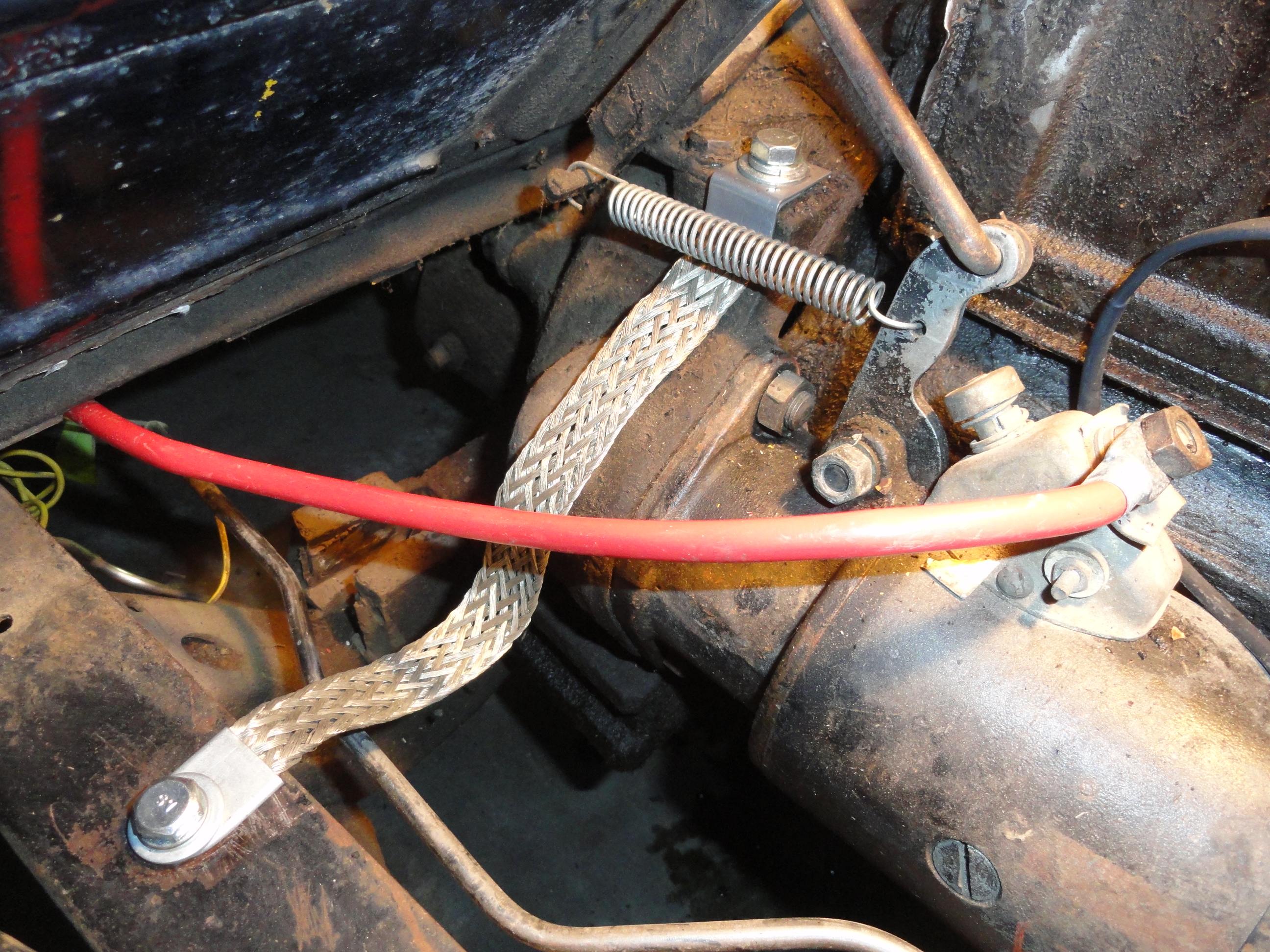
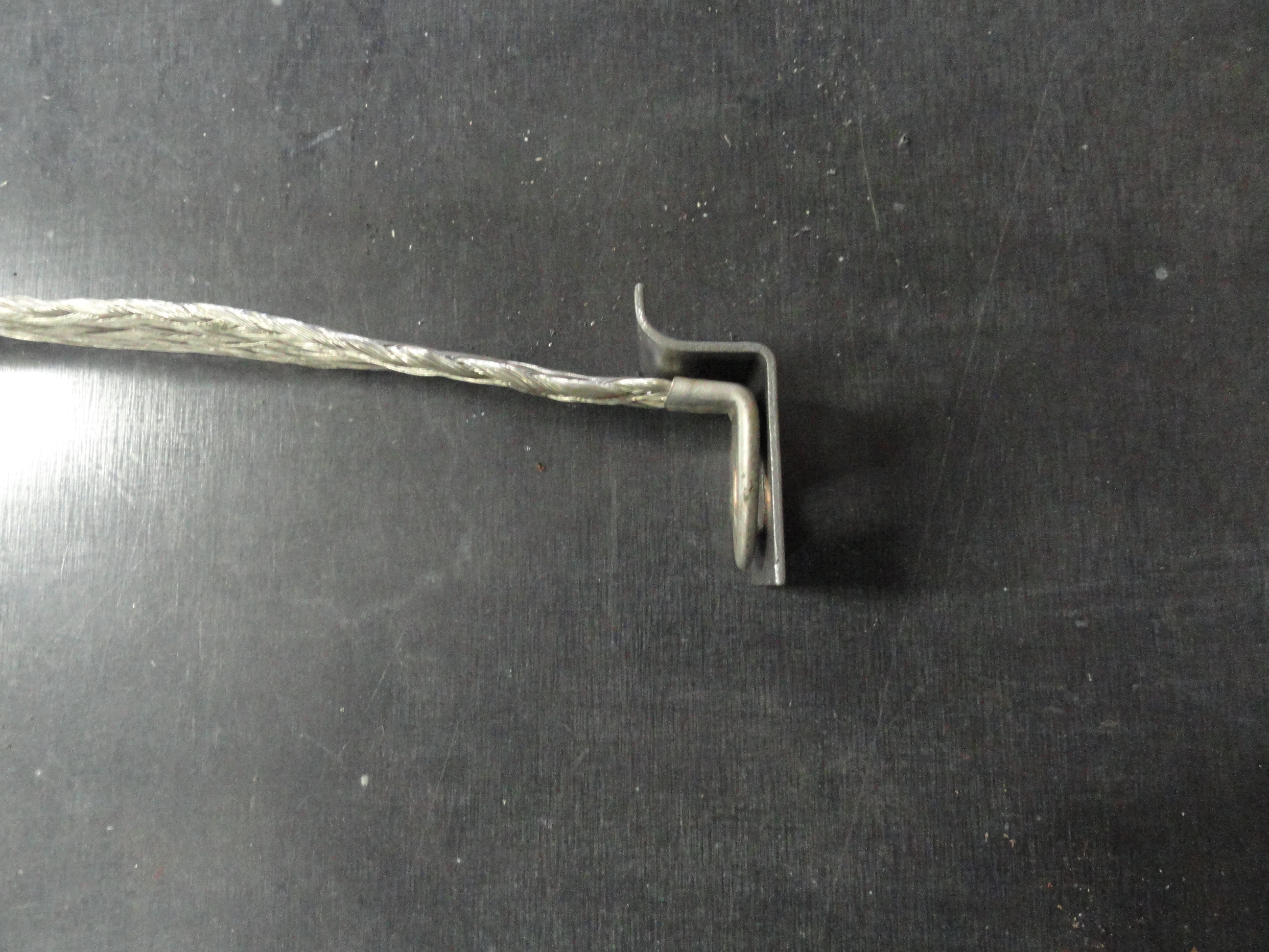
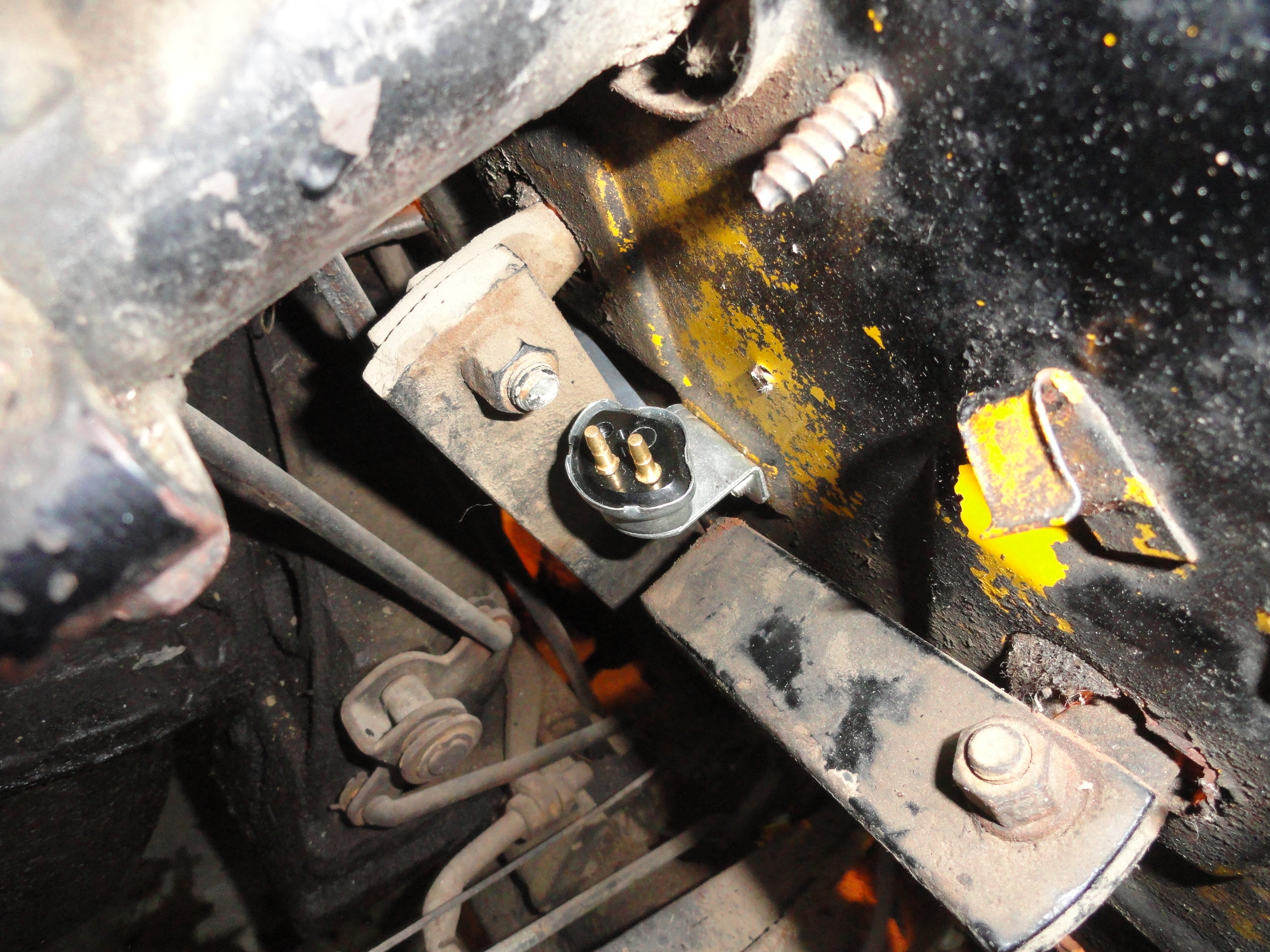
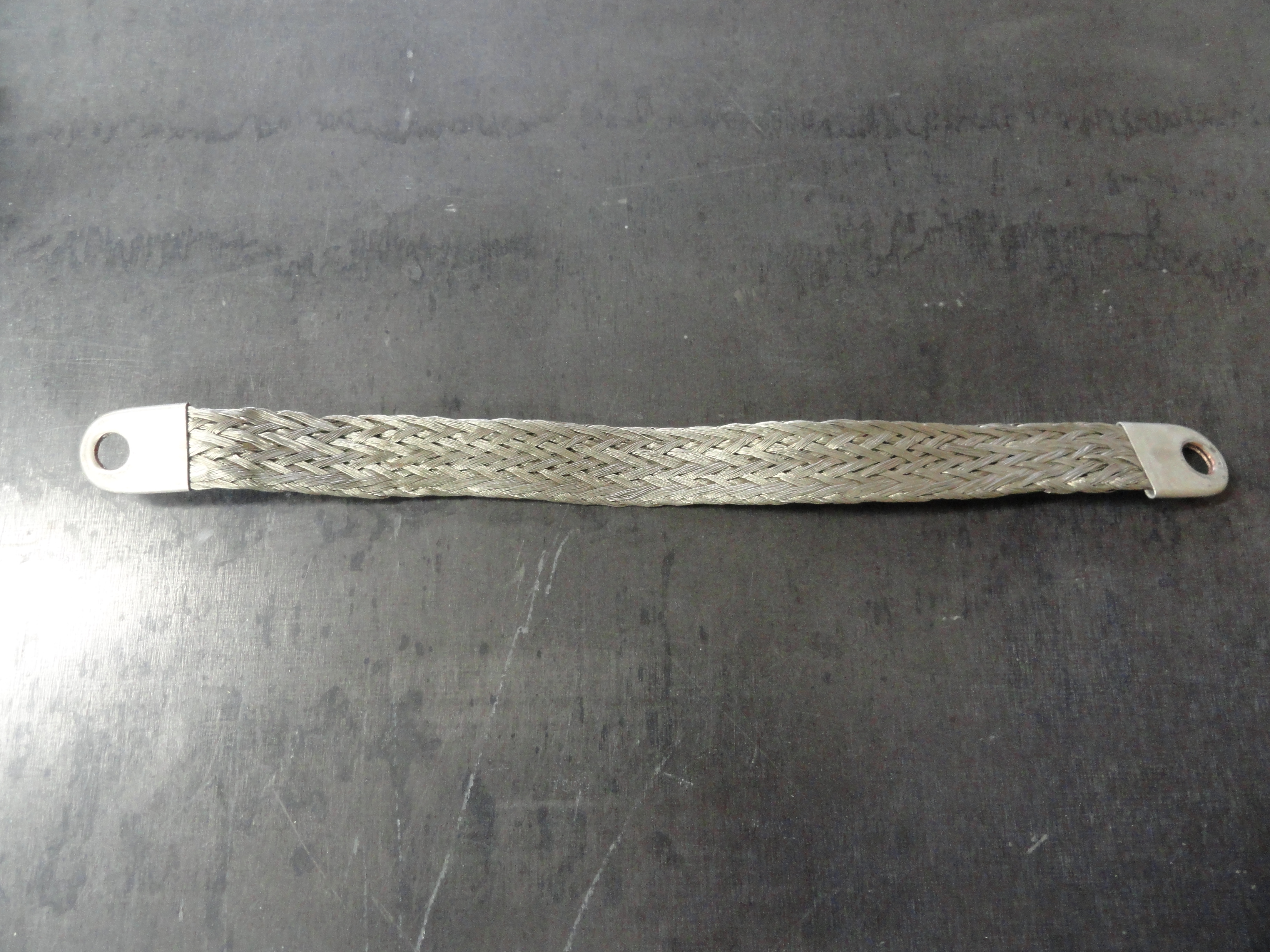
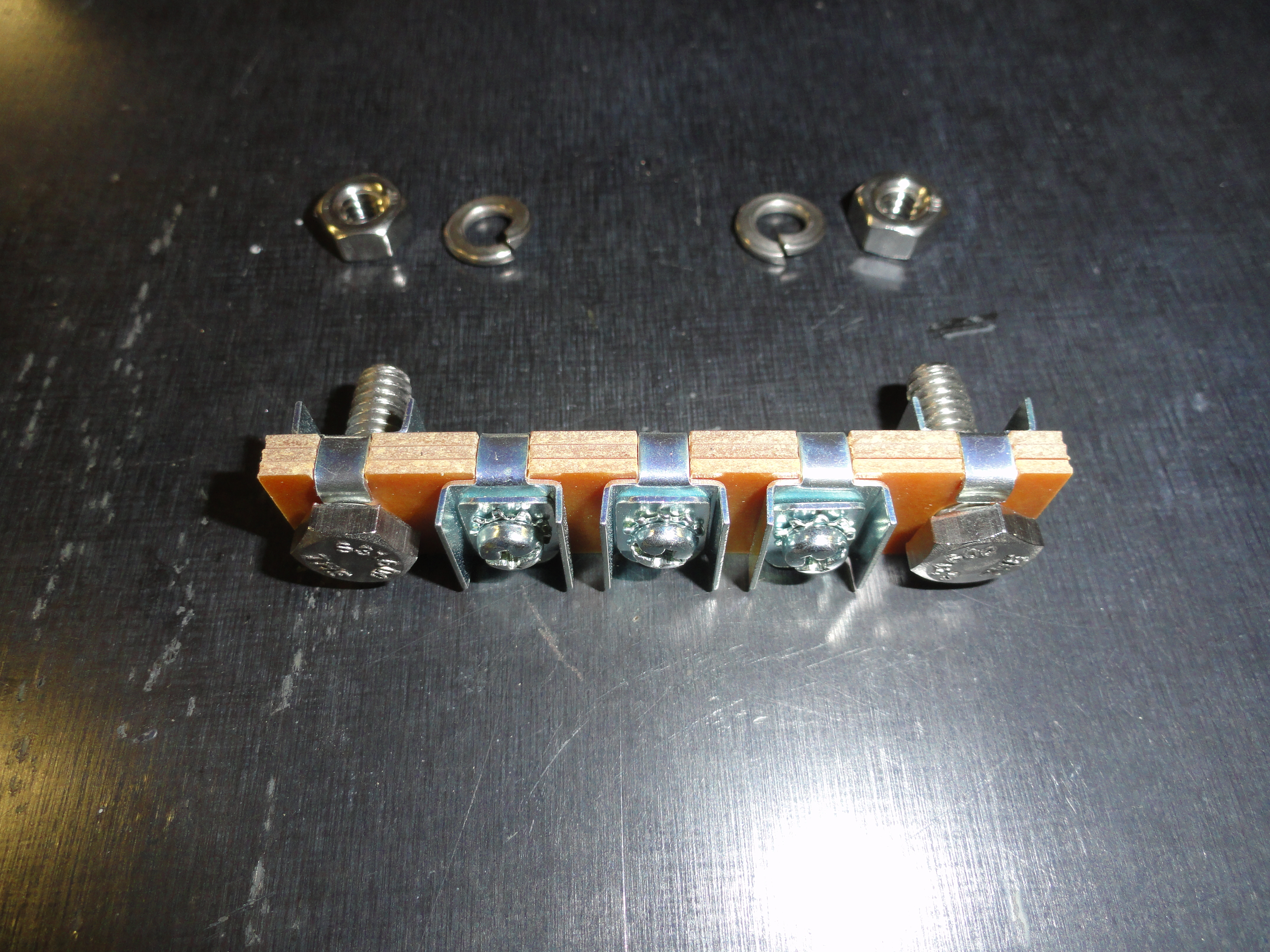
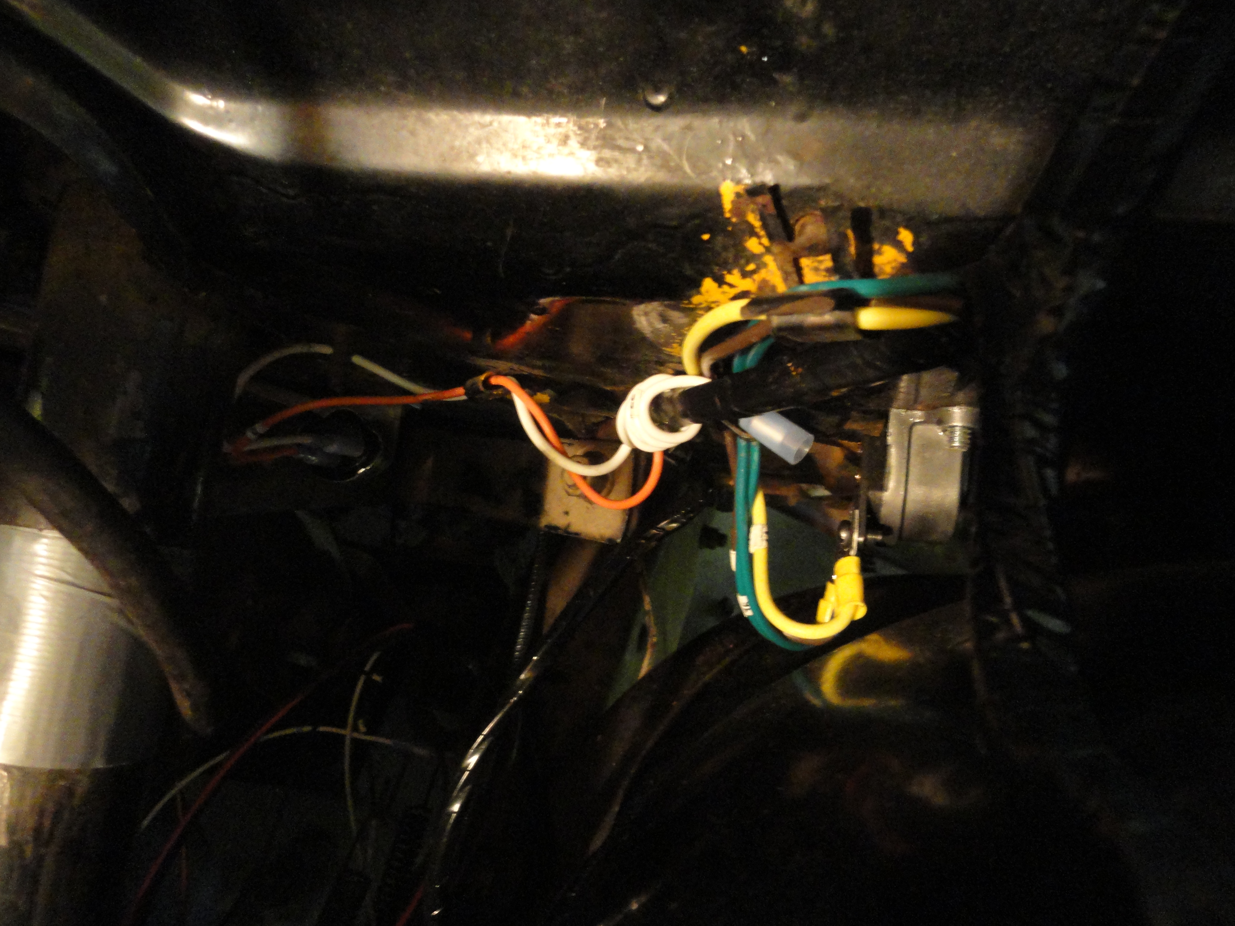
No need to worry about a good ground. Let's just change out the strap while we are at it. This is a typical 4 gauge strap used for 12 volt applications. If you are doing a 6 volt truck, be sure to get a 2 gauge version. There is an assembly to this part of the project. A small metal shroud that keeps the strap under the spring and out of the way should be present on the Bell Housing side as shown. To accommodate the bend you will also need to bend the strap as shown. This keeps the spring action working without interference. On the frame side, scrape away any paint or rust that may interfere with this systems sole purpose which is to provide a high amperage solid engine to frame ground. This will ensure good starter action as well as give all engine electricals the same ground potential as the rest of the truck.
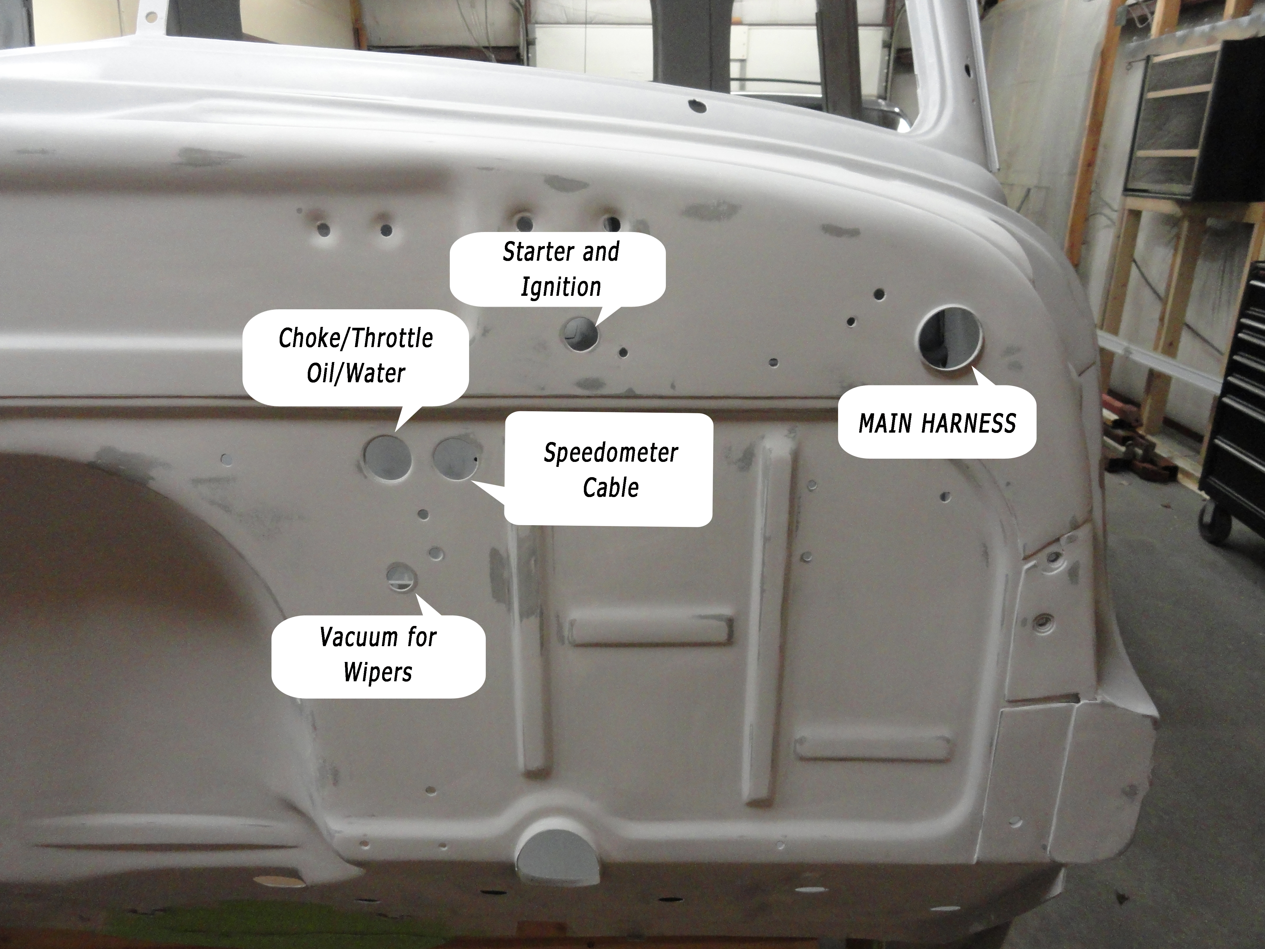
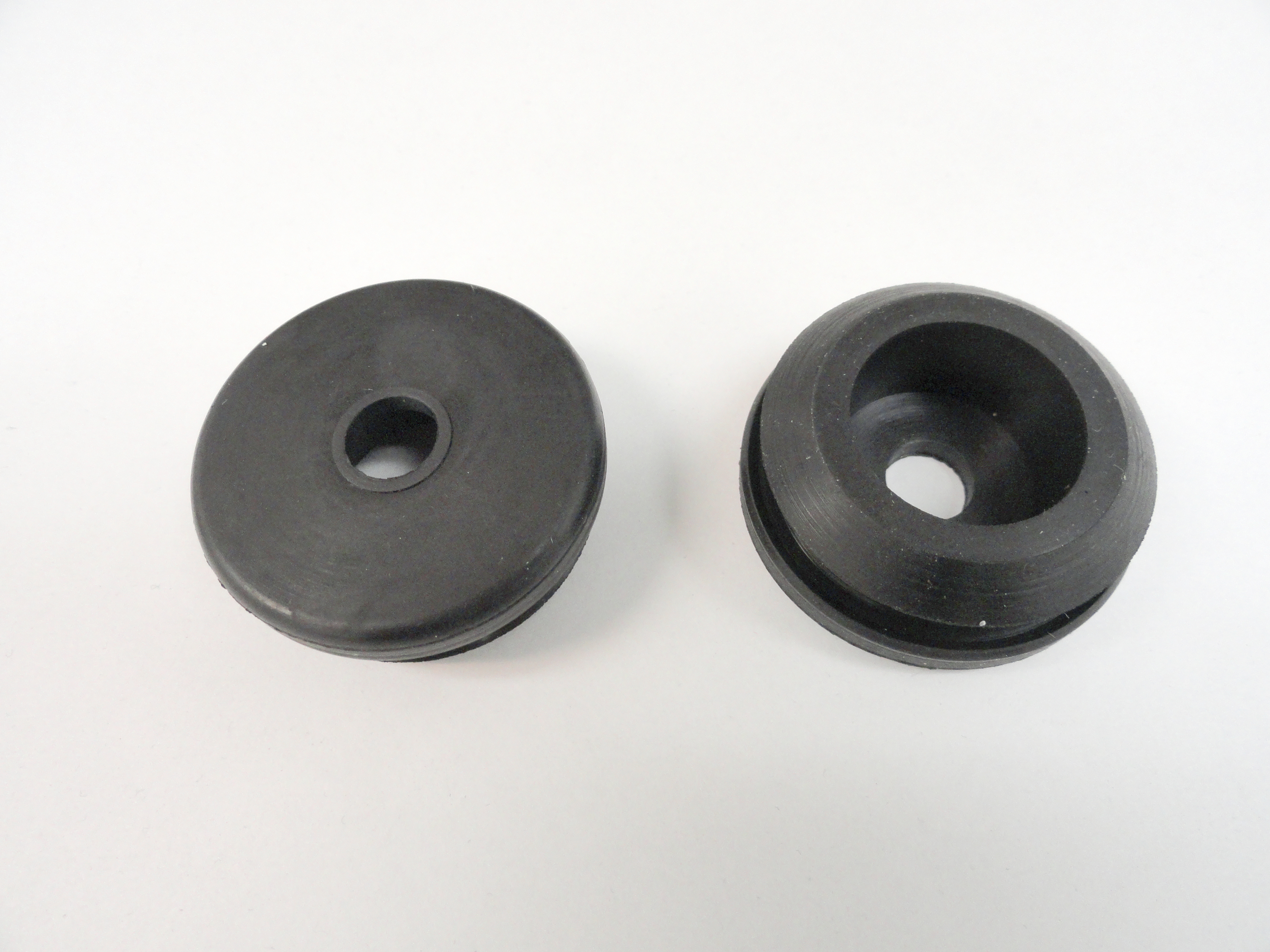
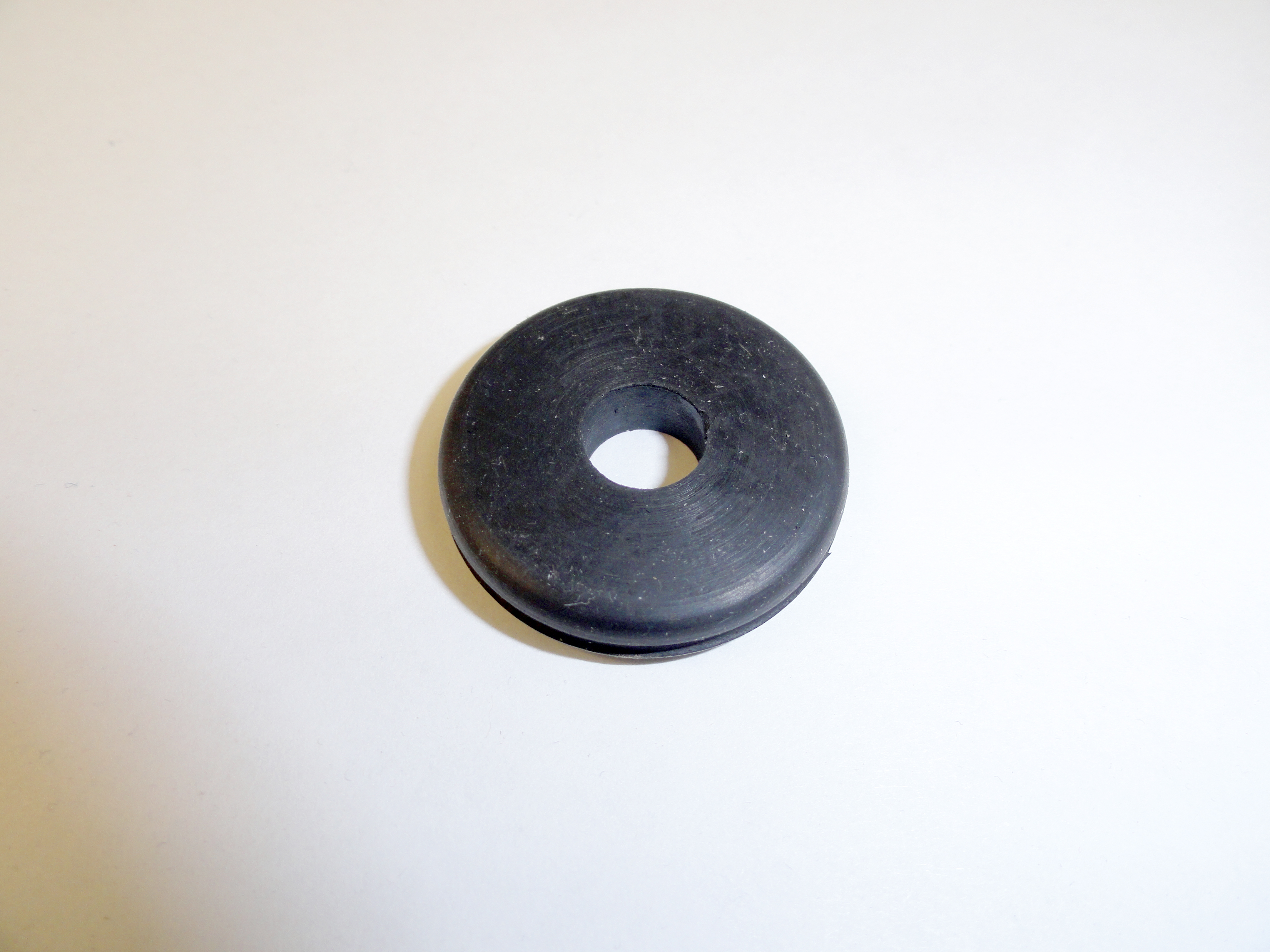
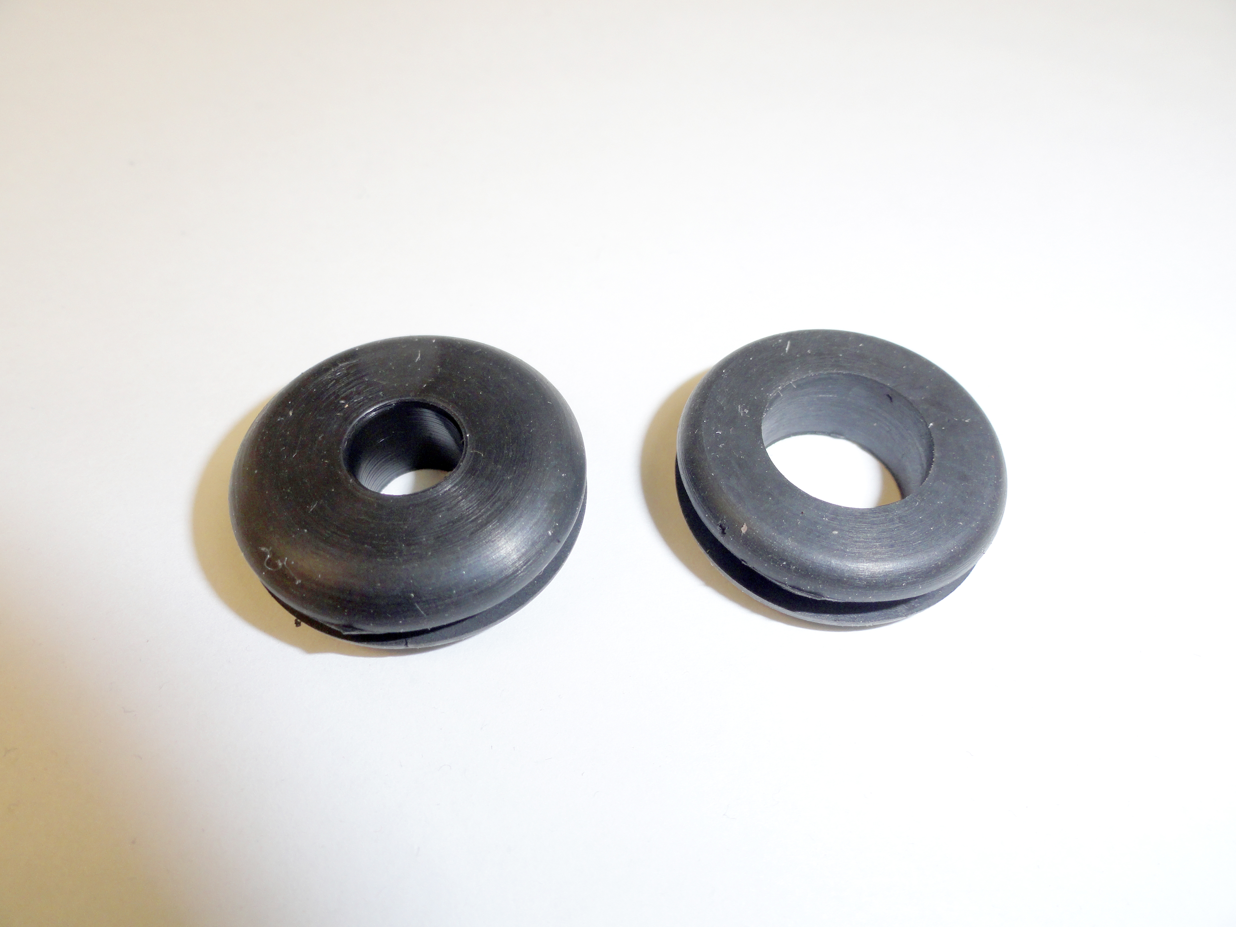
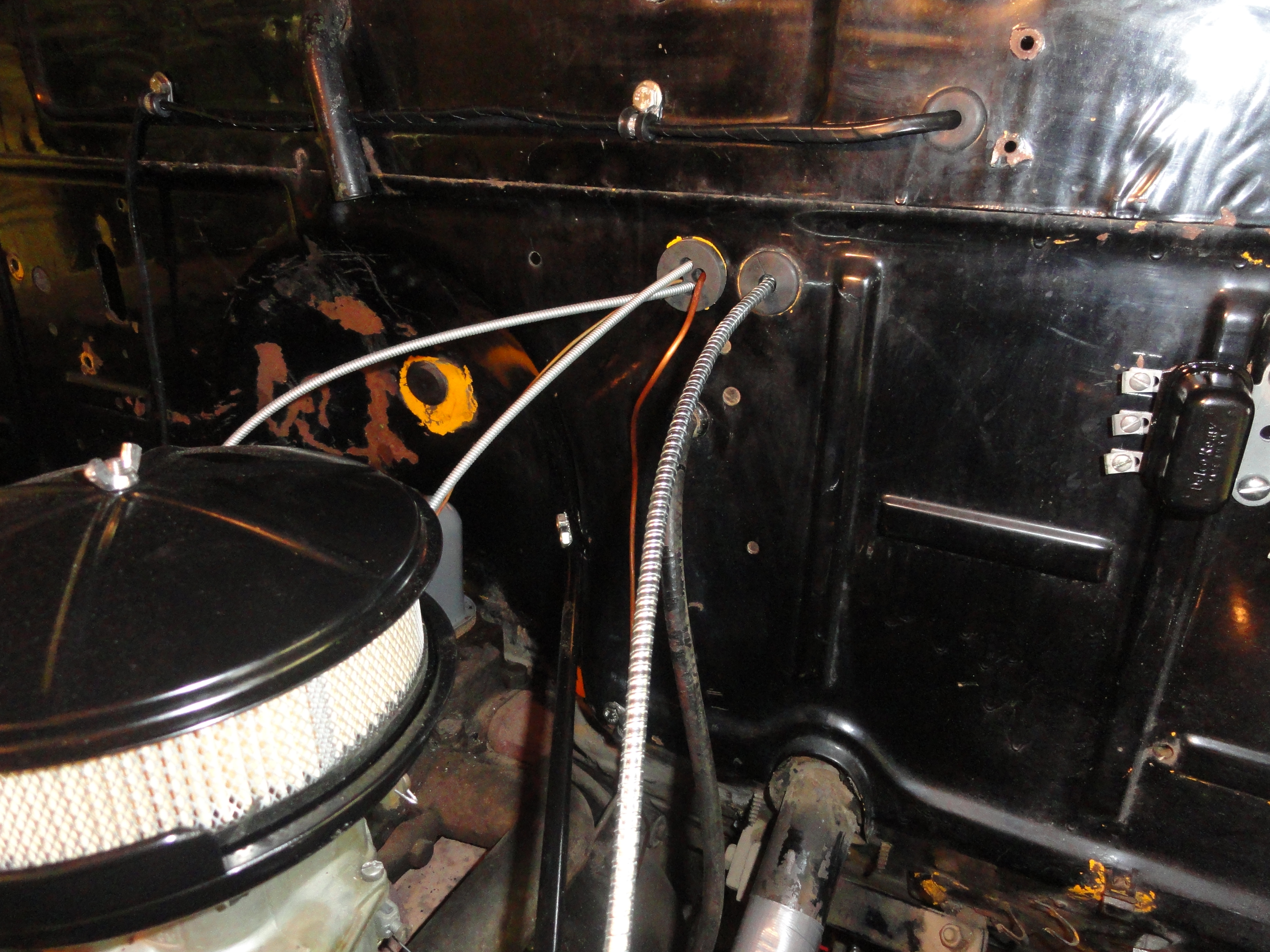
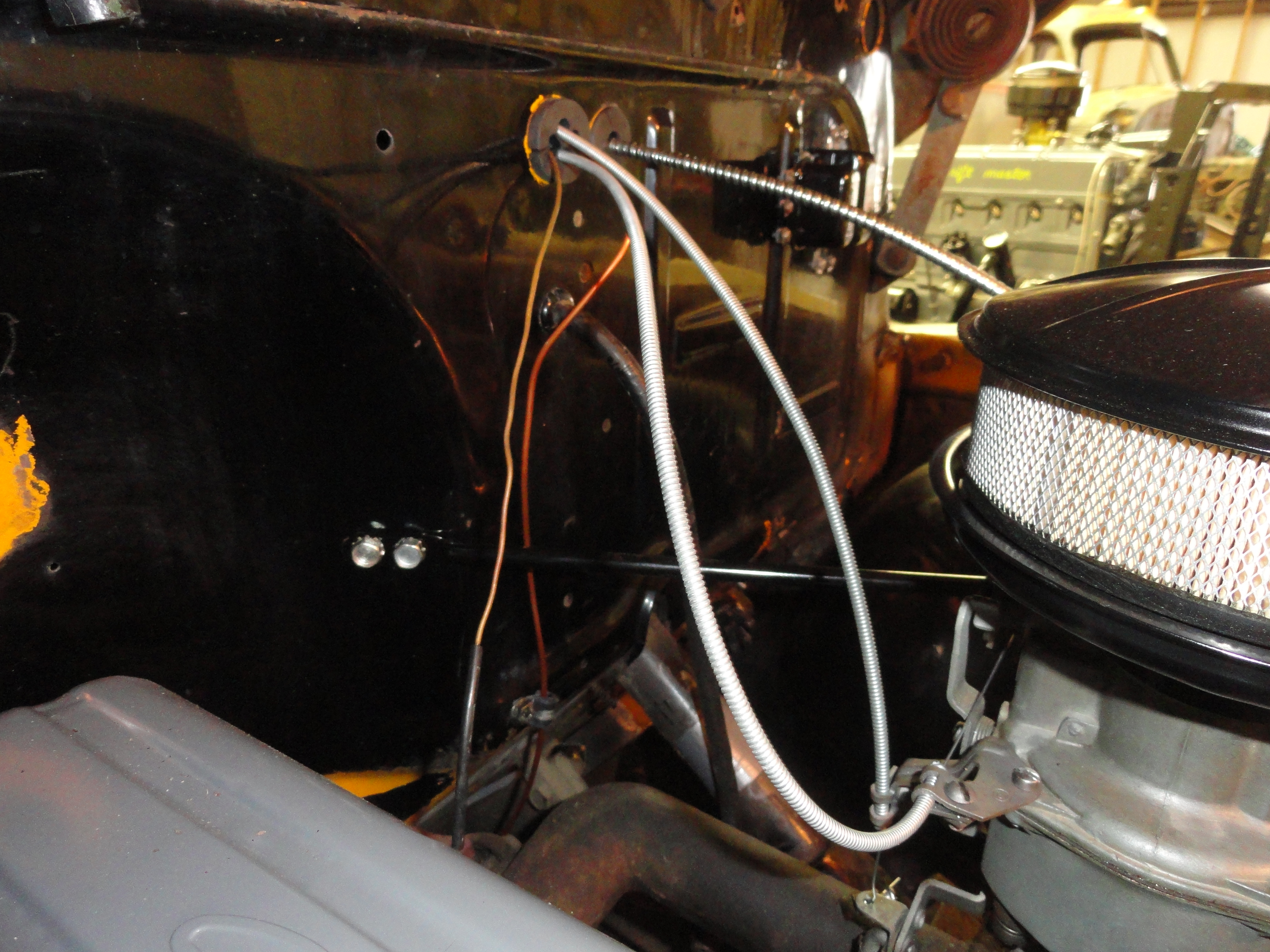
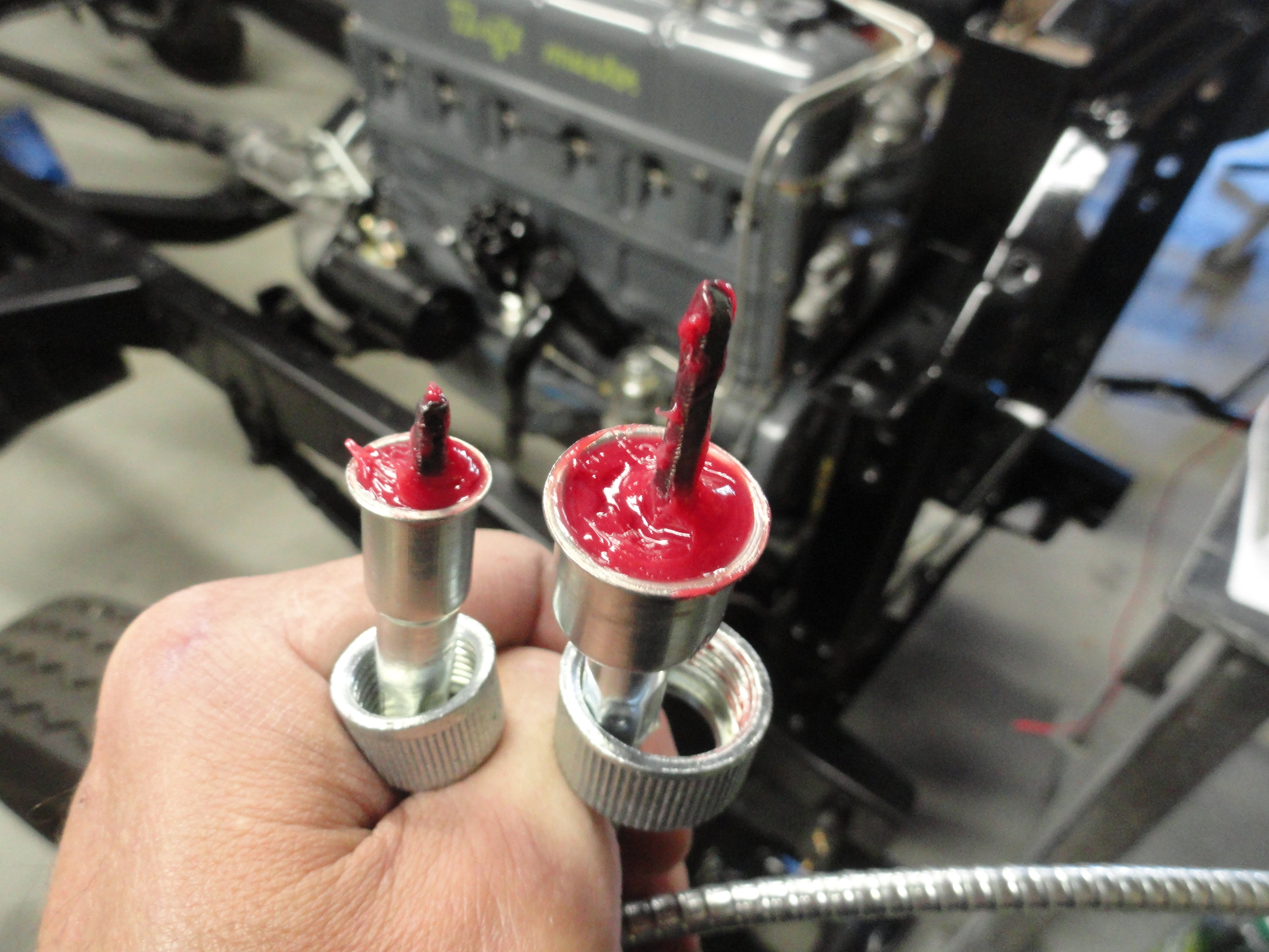
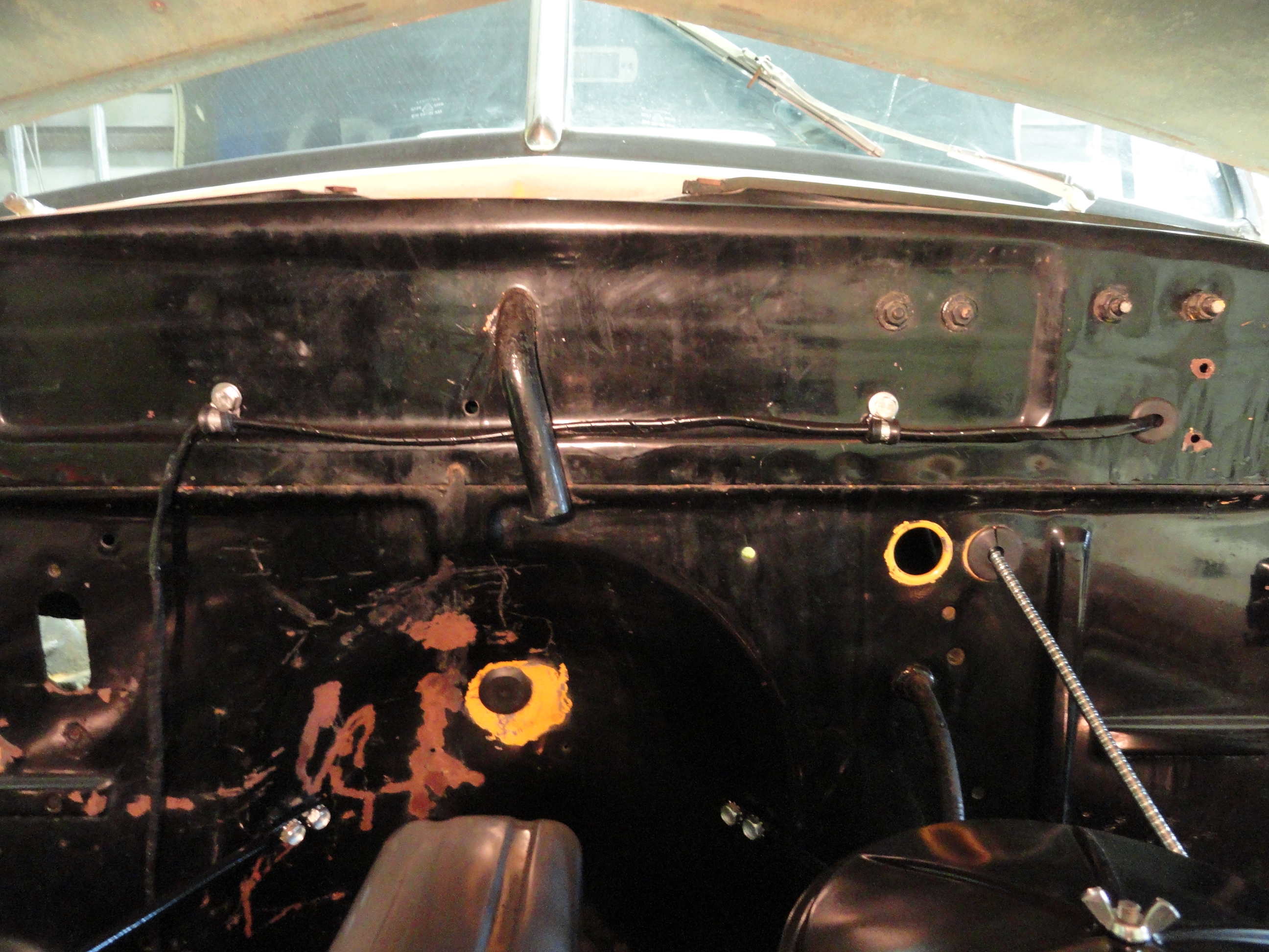
Use the diagram to the left to decide which grommet goes where. Each grommet once you have them in your hands will be apparent as to where they go. In the picture gallery at the bottom of this article are pictures of each one. The only one that I did not mess with was the Wiper Vac grommet since my future plans include an electric wiper system. These grommets represent the stock locations for each of the wires or parts that go through them. There are two grommets that require modification in order to fit the application.
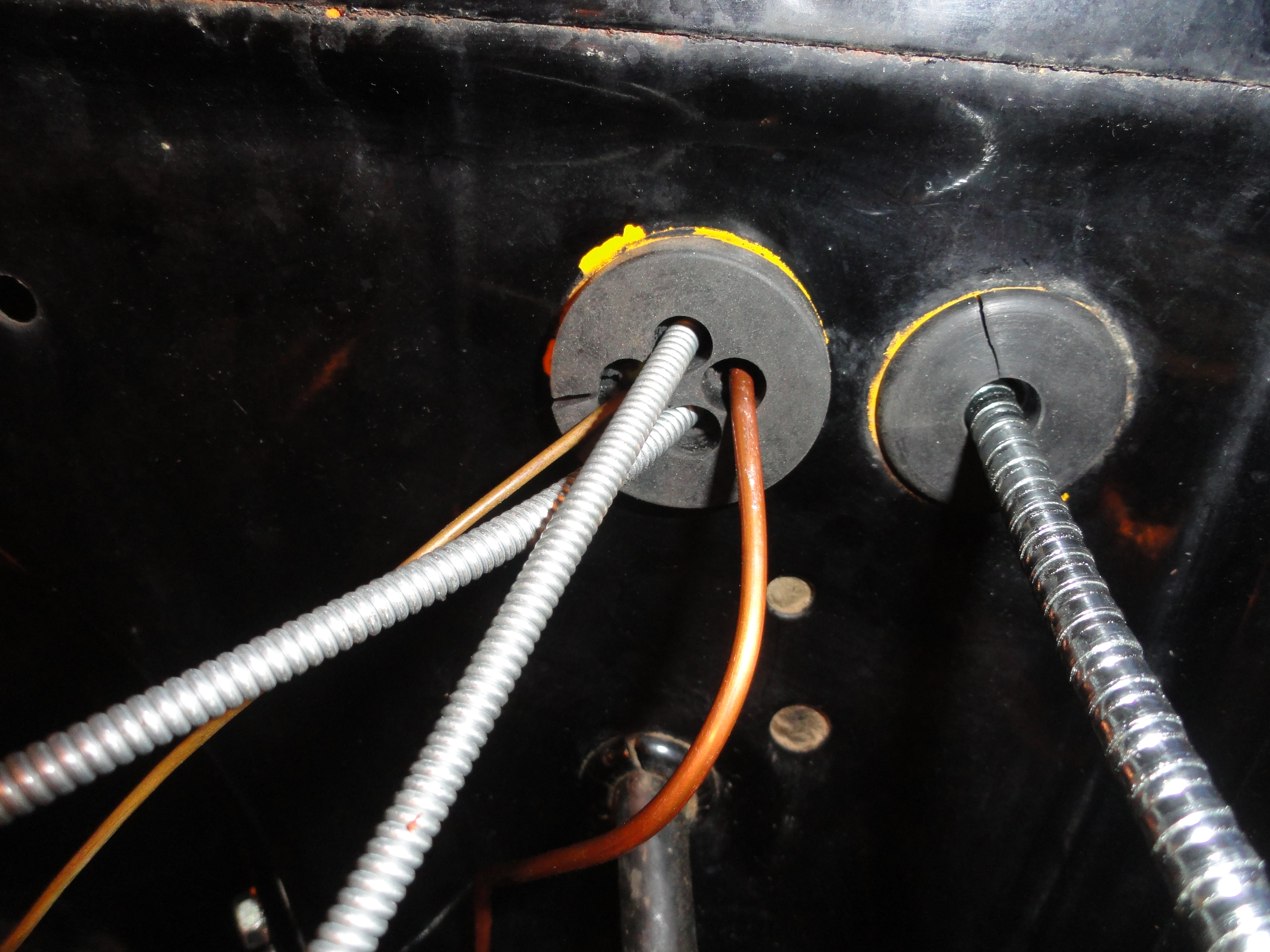
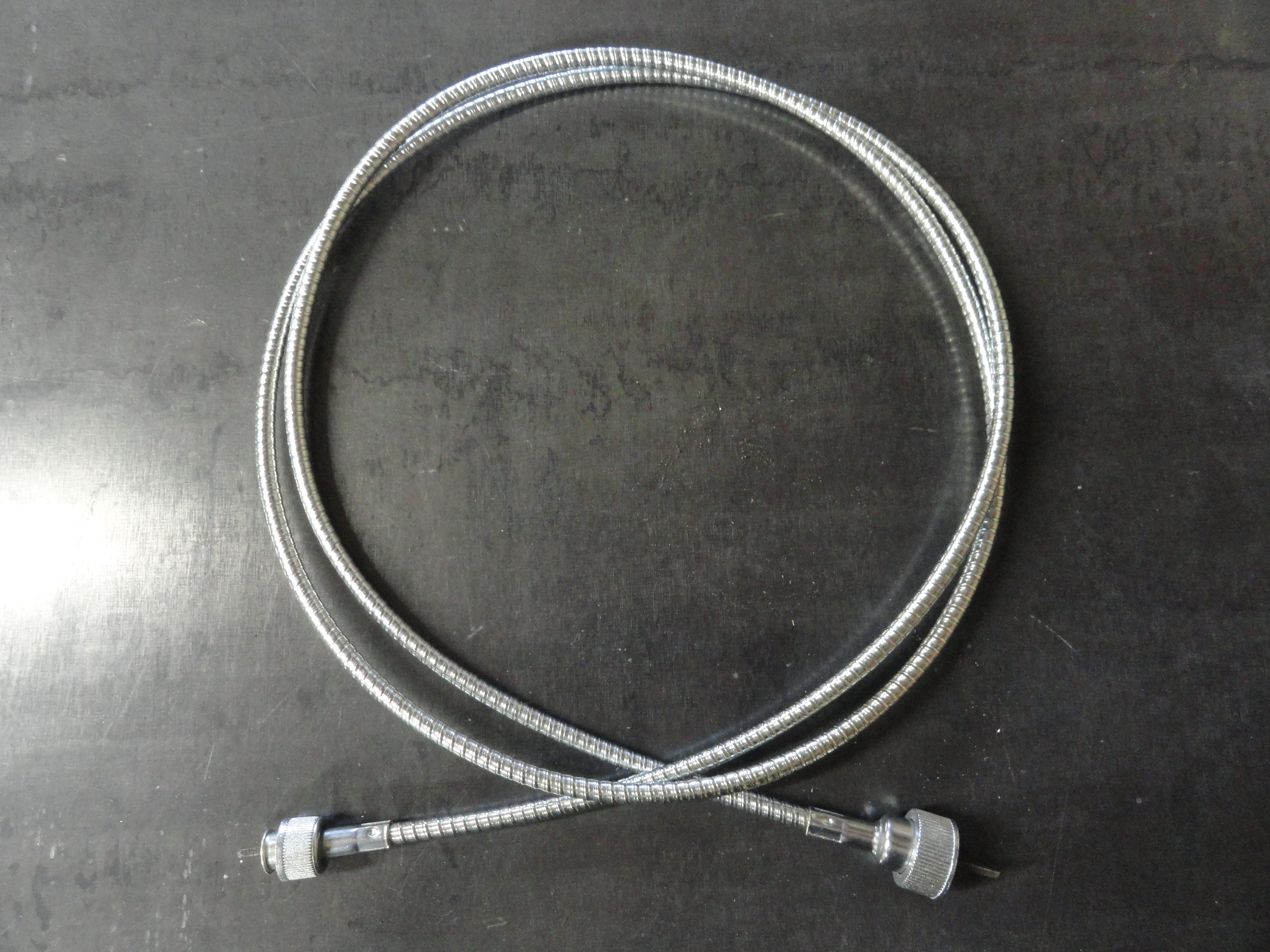
Once you feed the water temperature gauge copper line back into the 4-hole grommet, you can reattach the sender to the Engines Head and then refill your cooling system. You can also take this opportunity to attach the oil pressure line back up by putting that copper line through the grommet on the opposite side. As long as the gauge is still accessible for the wiring part, you are good to go. You can also put the choke/throttle cables through the 4 hole grommet completing this grommets installation. The same can be said for the speedometer cable as shown. These are two grommets that have little to do with the harness installation but it's good to replace all of them at the same time.
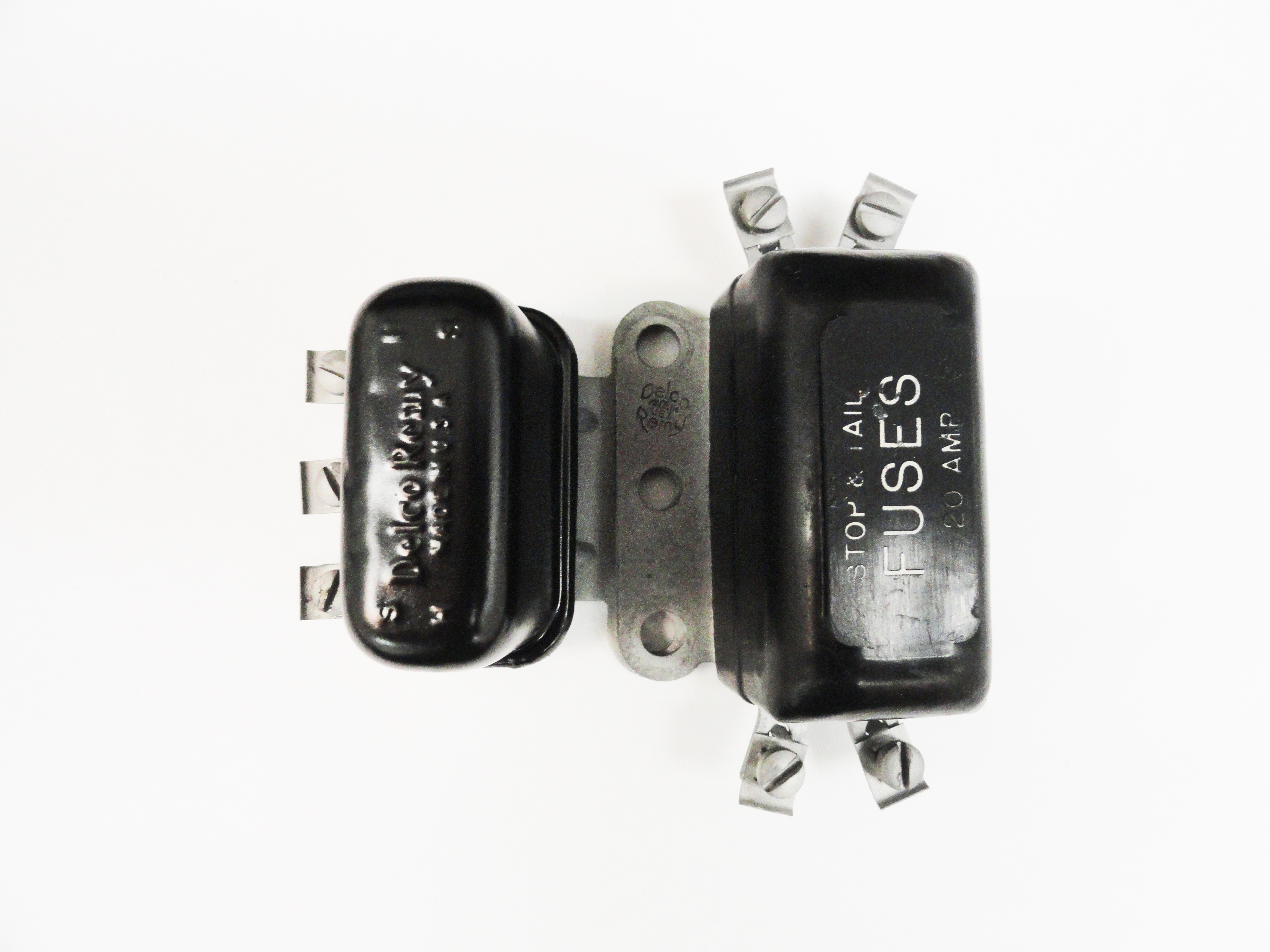
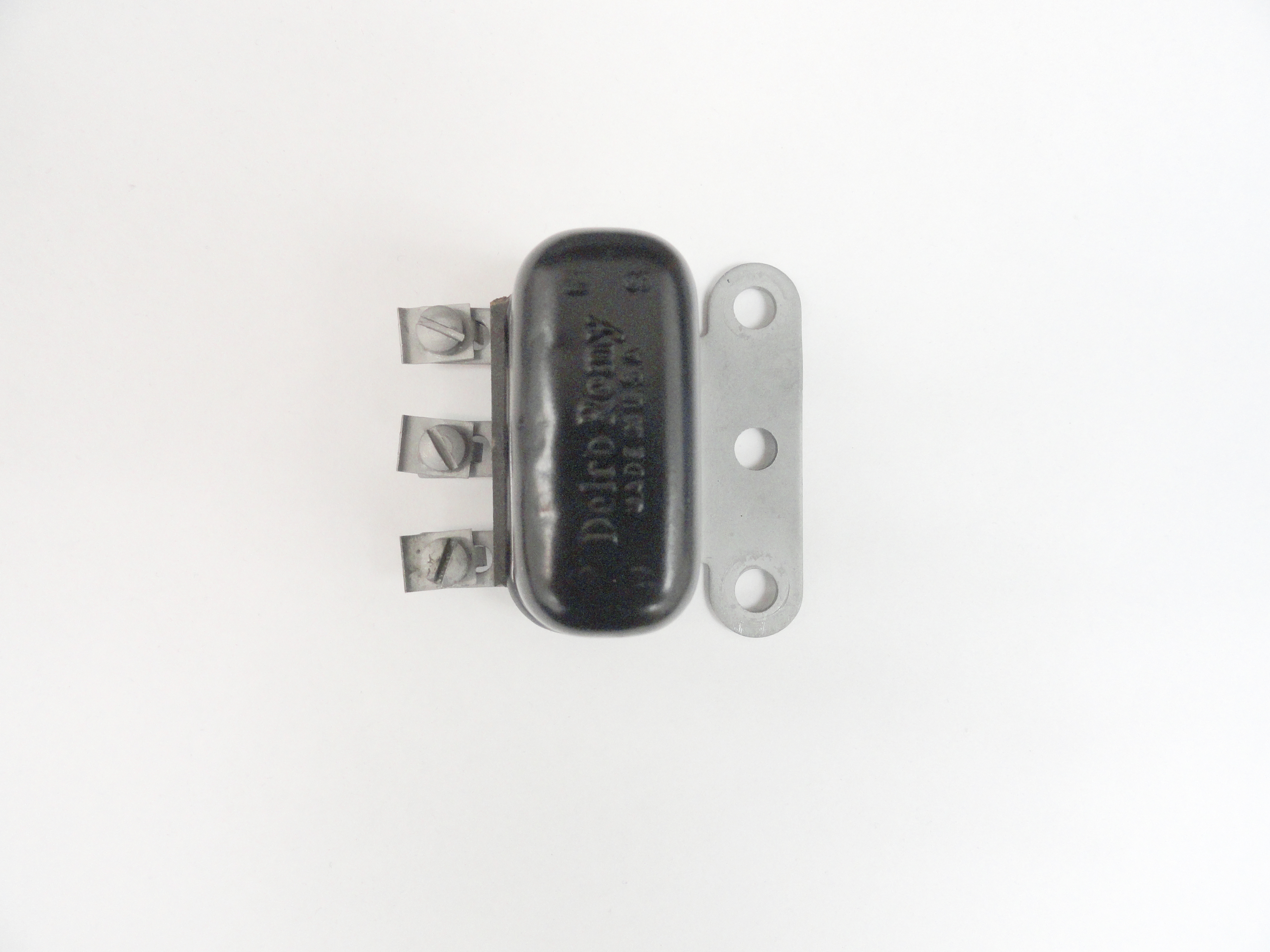
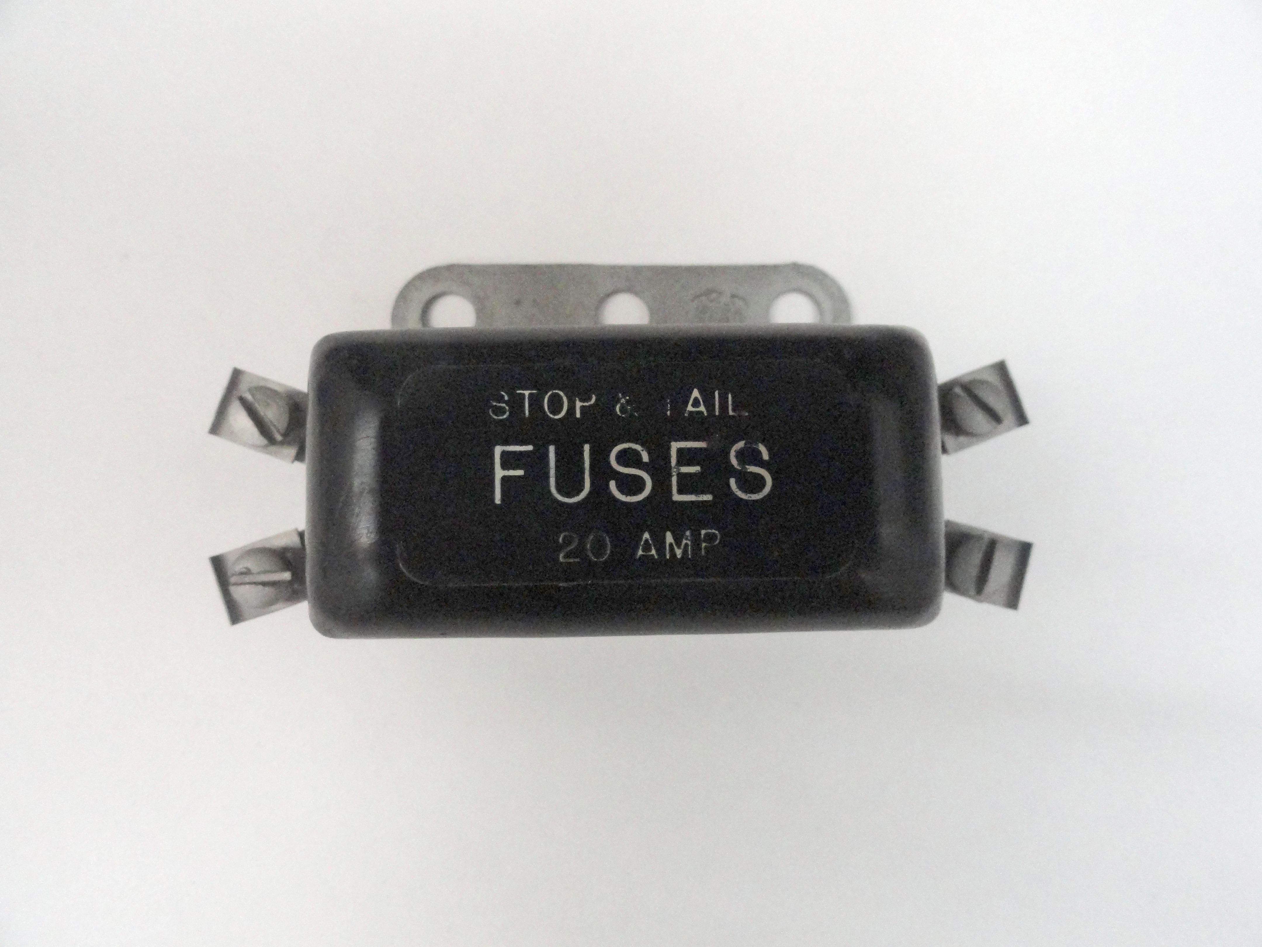
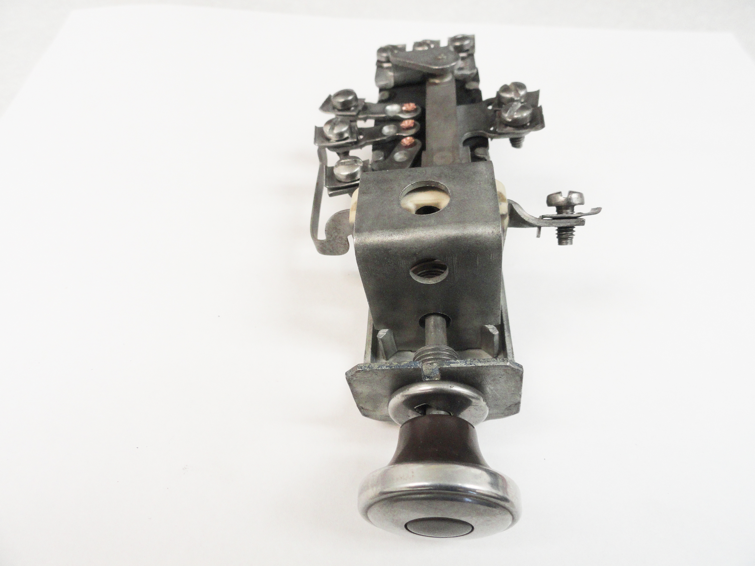
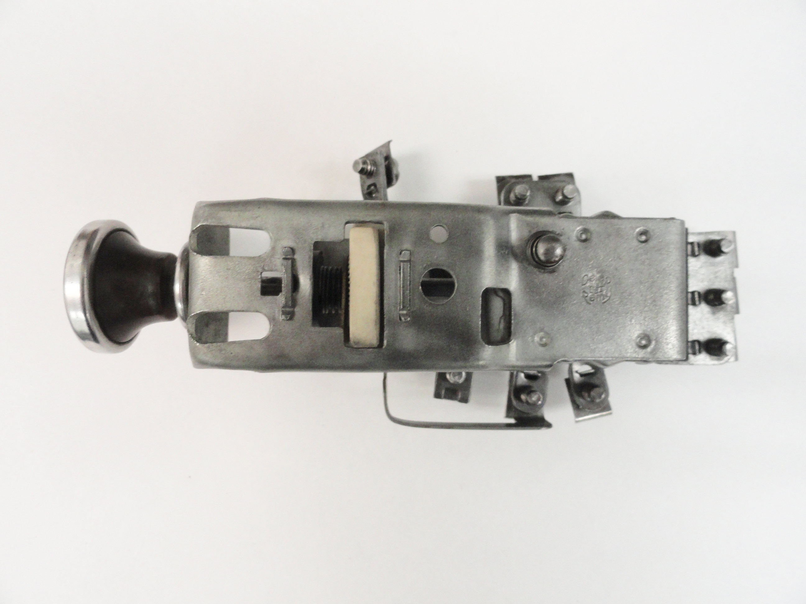
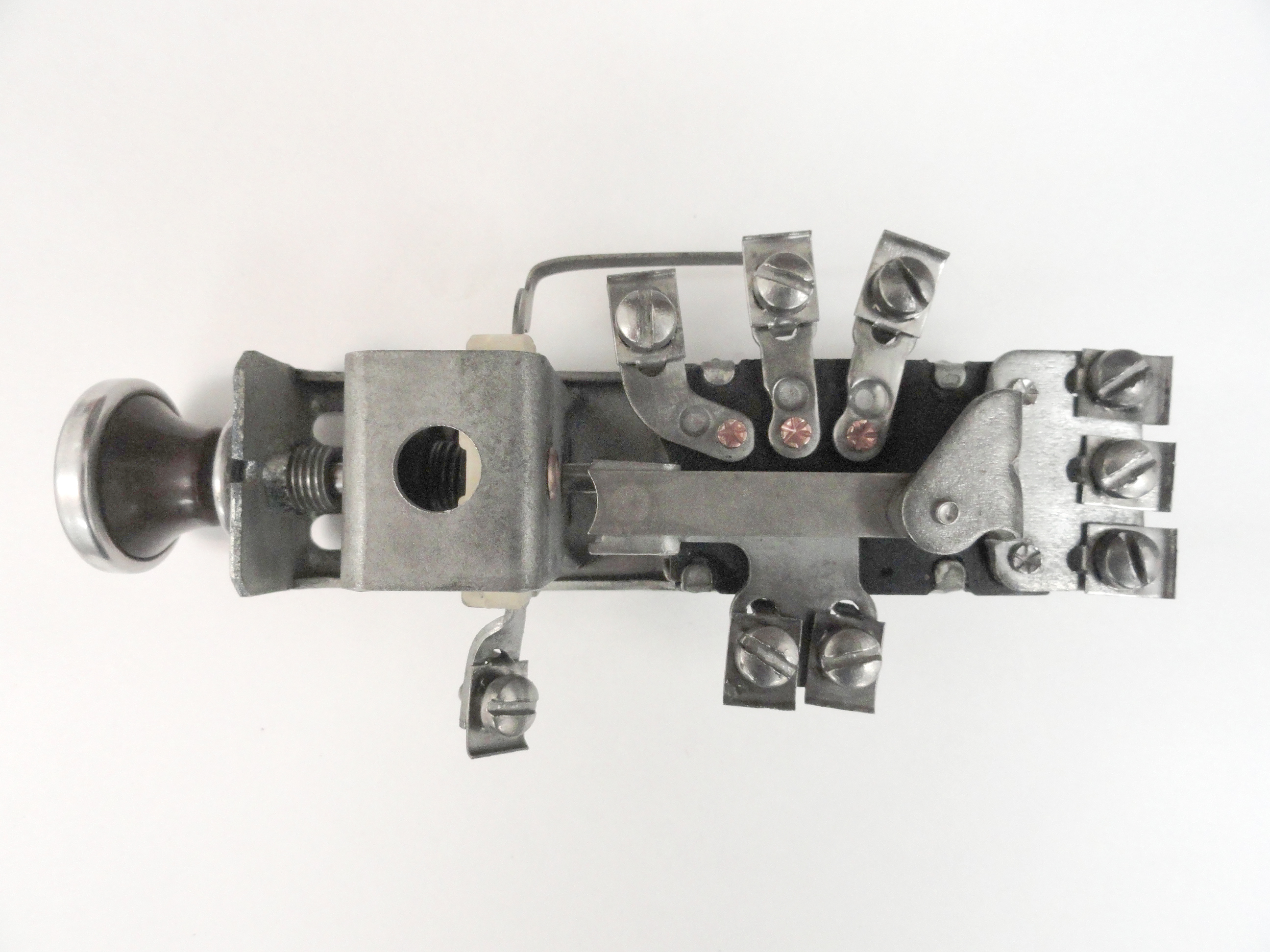
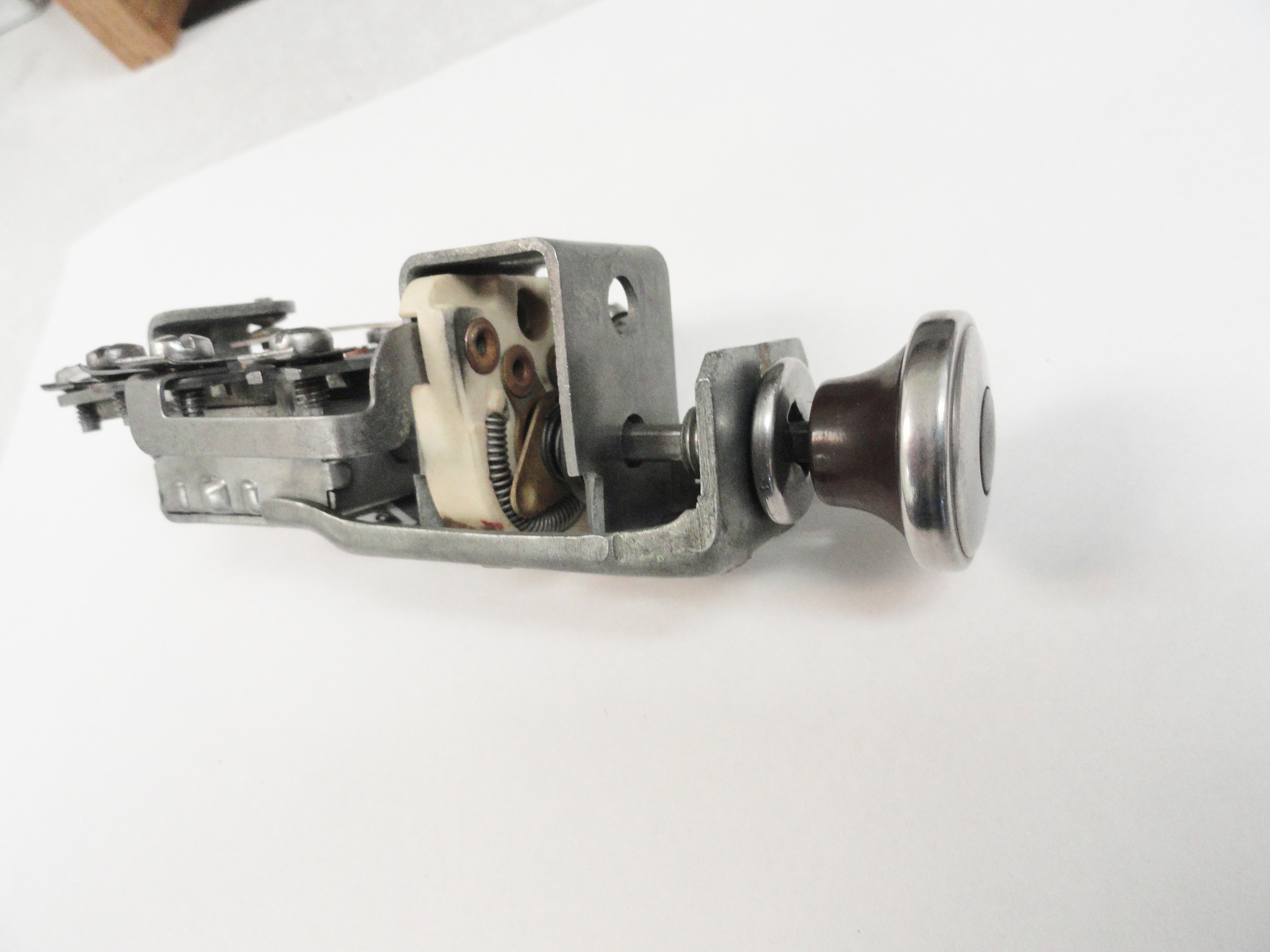
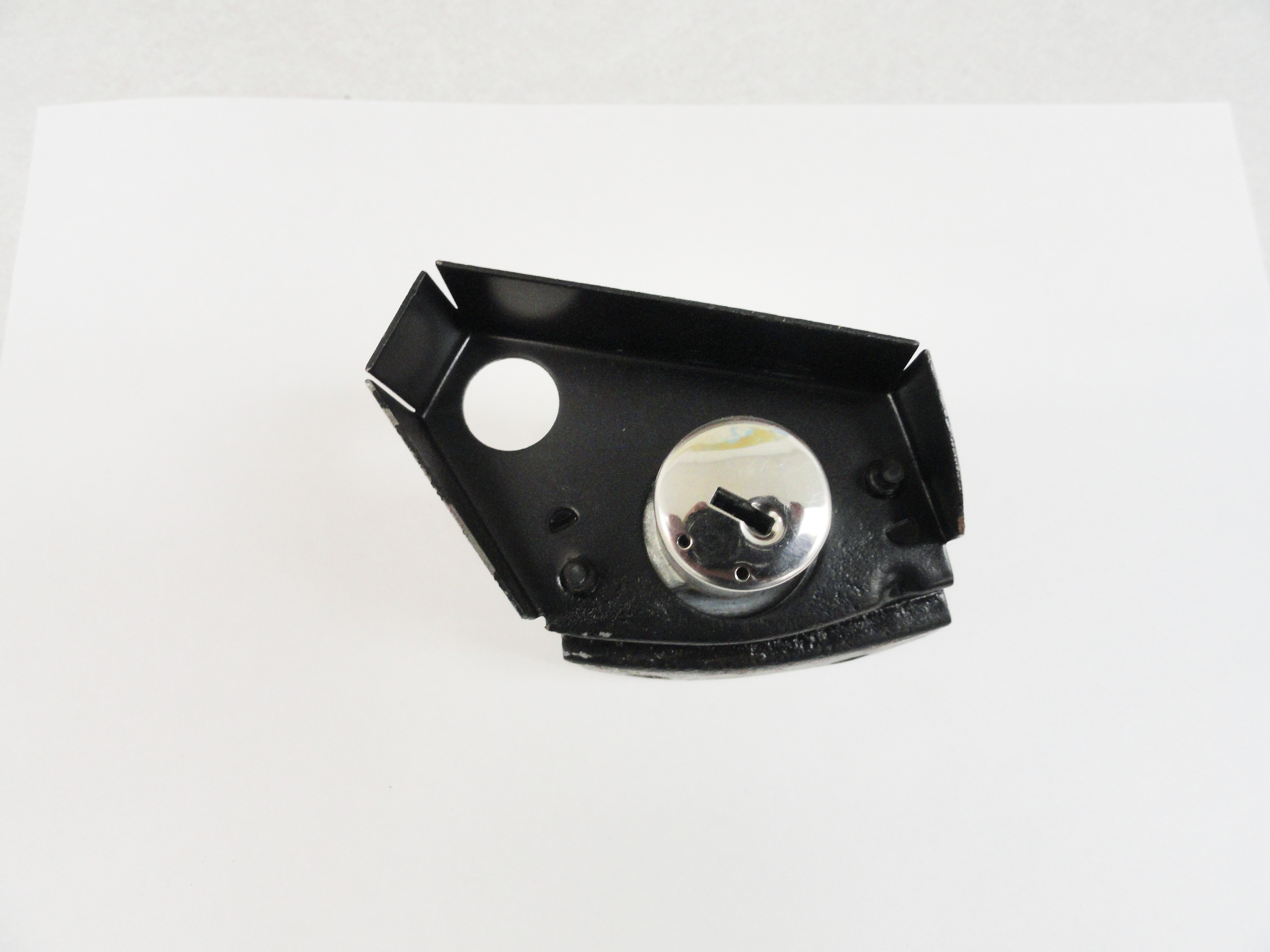
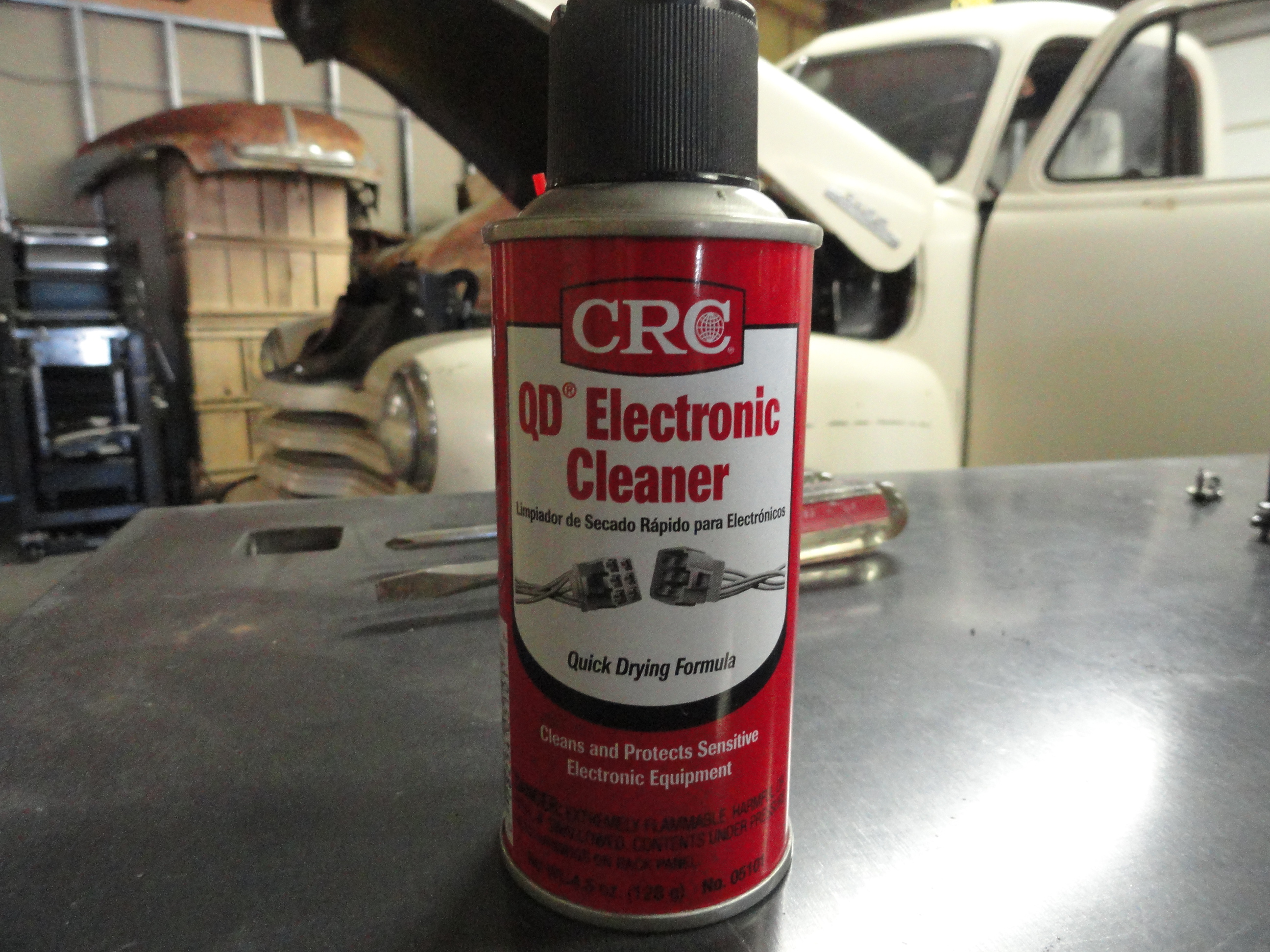
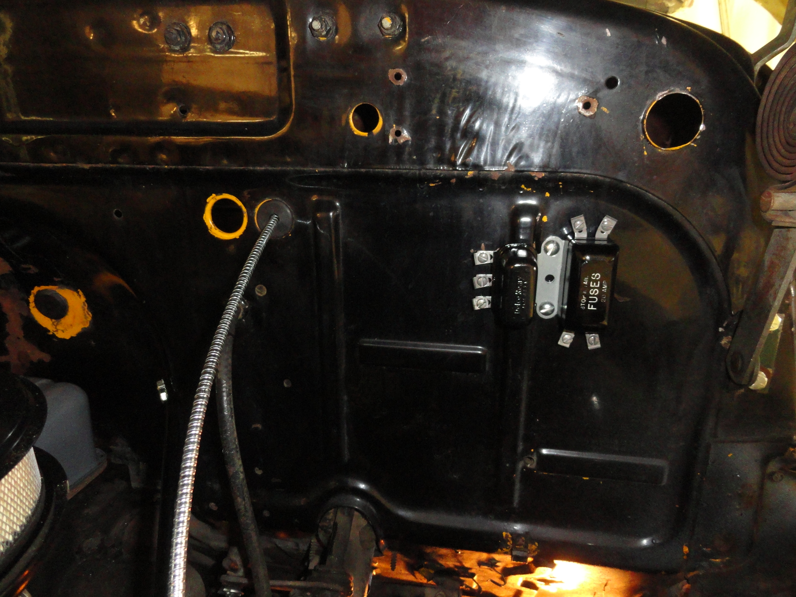
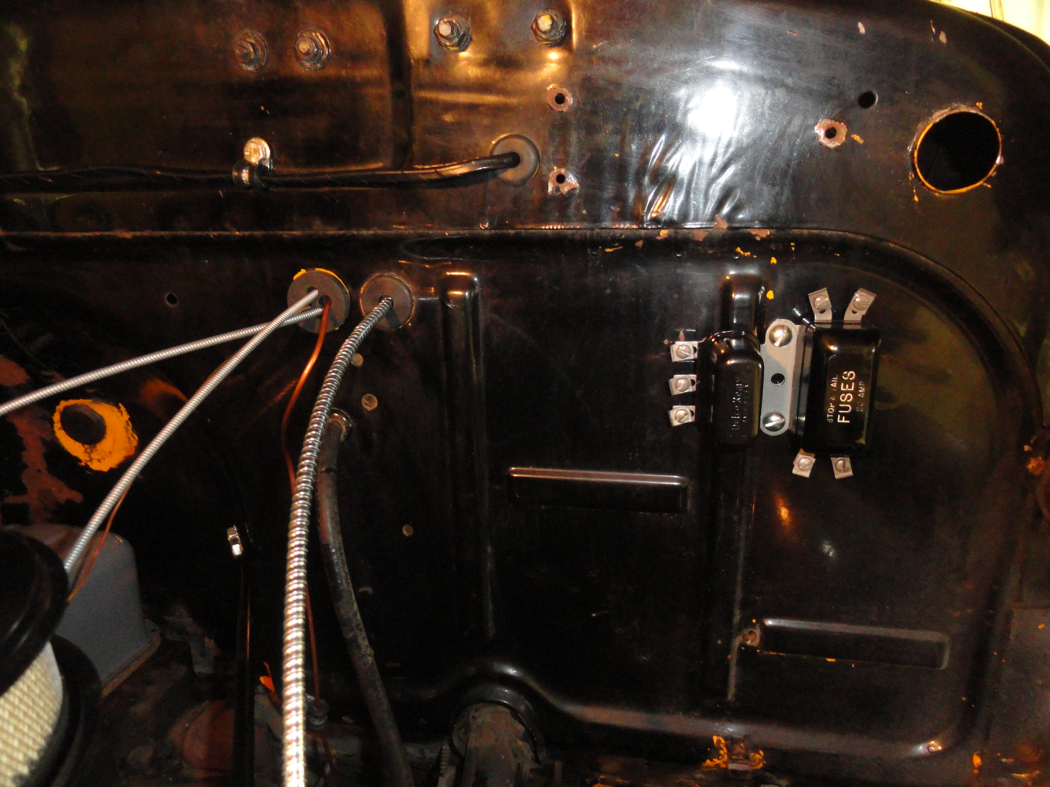
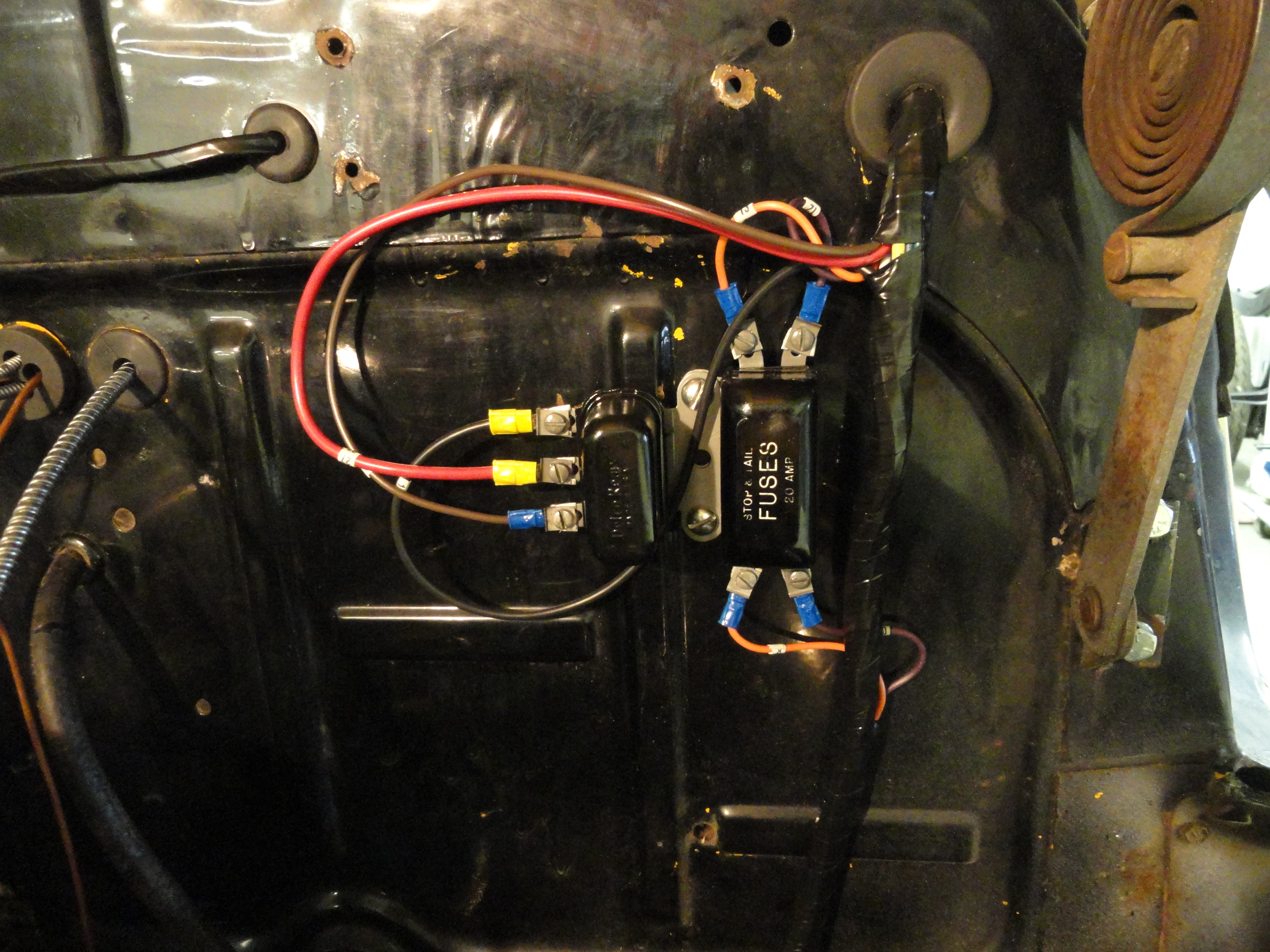
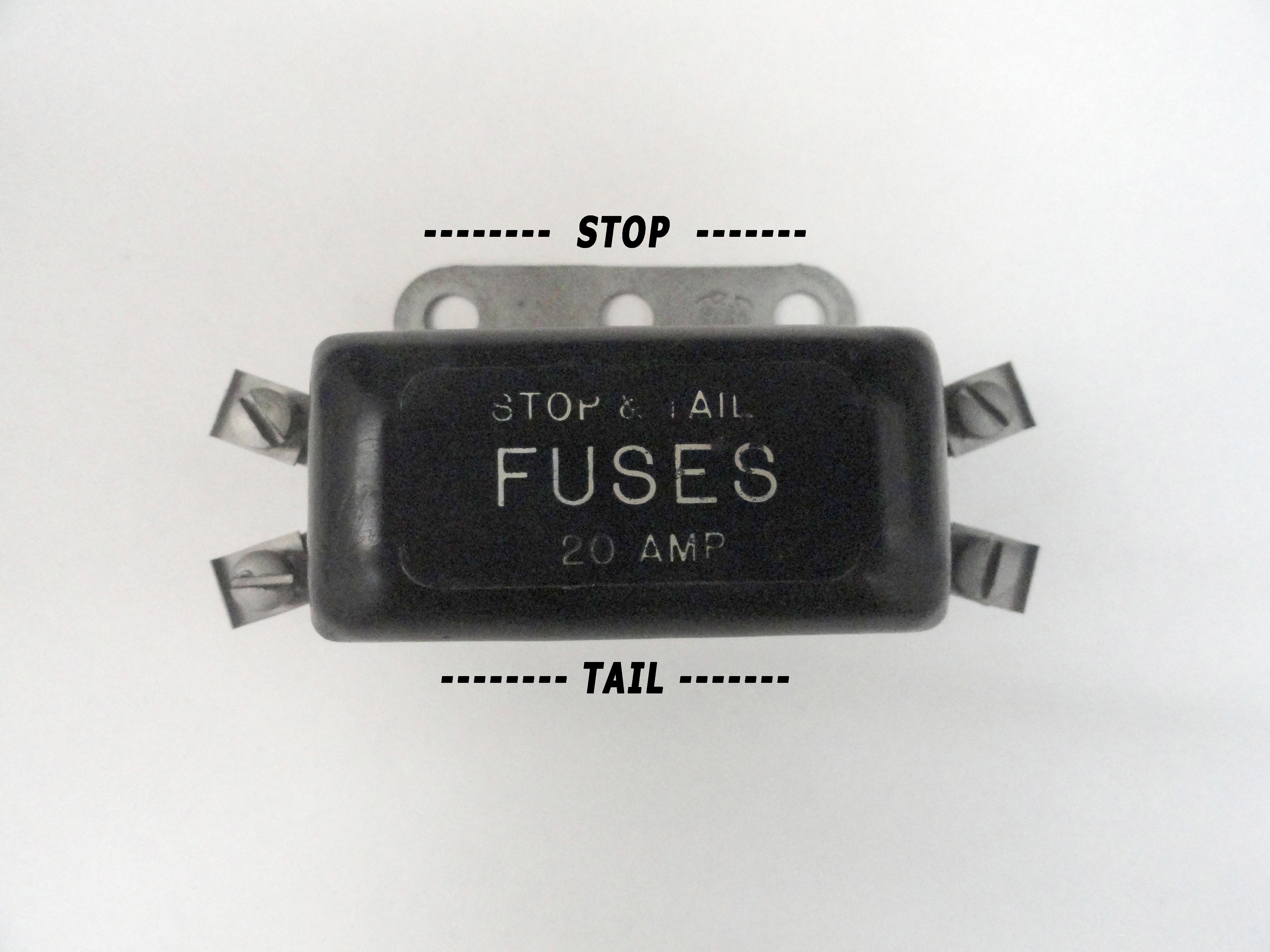
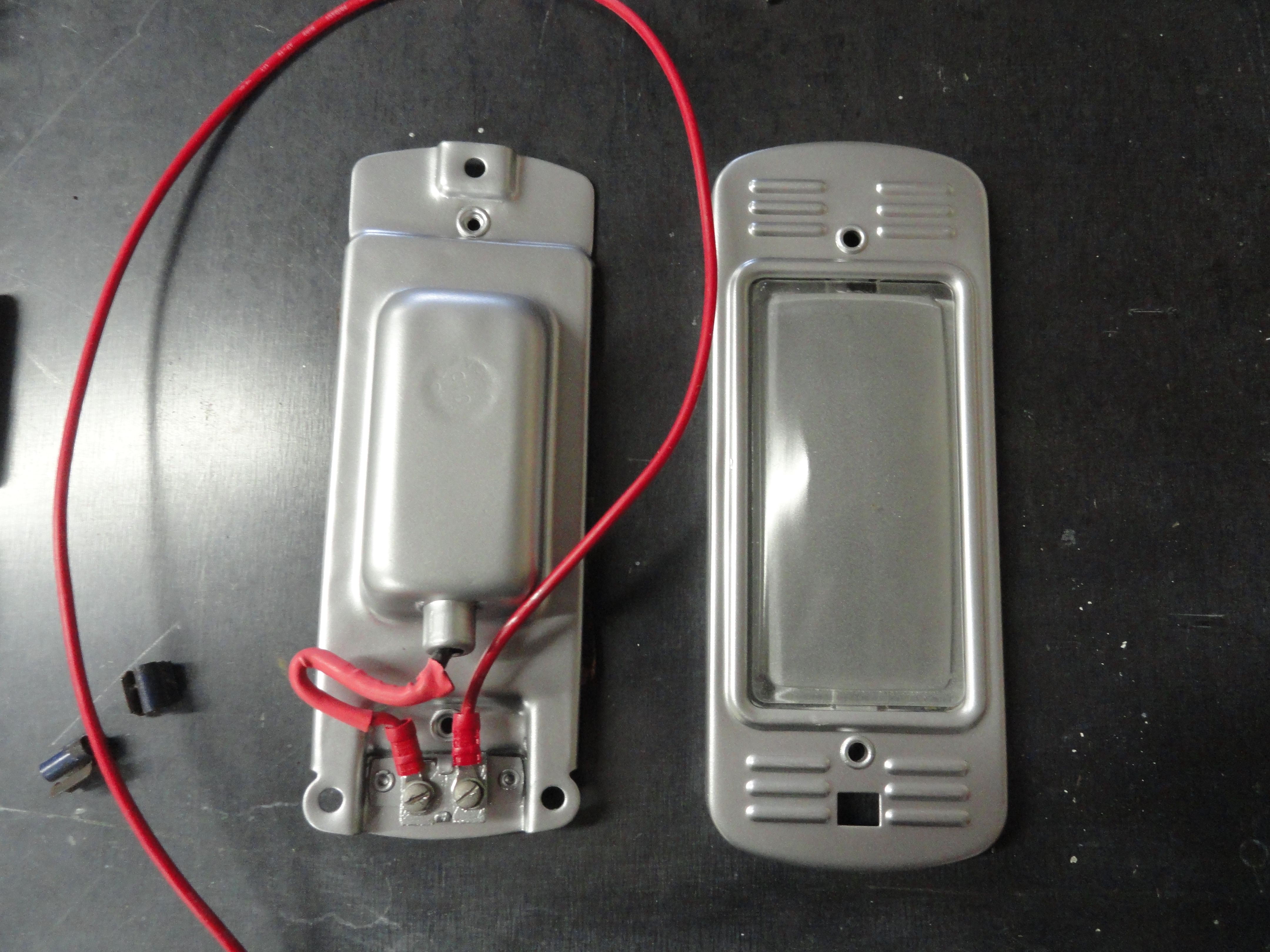
I didn't want to put defective parts back on the firewall and then find out after I have the new harness in, so I remove the these two items from the firewall to check them for serviceability. I open the covers and spray them really good with electronic contact spray. I then take a fine wire brush on the end of a Dremel tool to clean the screw terminals thoroughly. I want everything to work! The fuse block is used only for the Brake Lights and Tail Lights. Both are 20 amp circuits that use 20 amp fuses. There is a fuseholder in the inside of the cover for spares. As it is oriented on the firewall, the left side is for the Brake lights, the right side for the Tail lights as shown right.
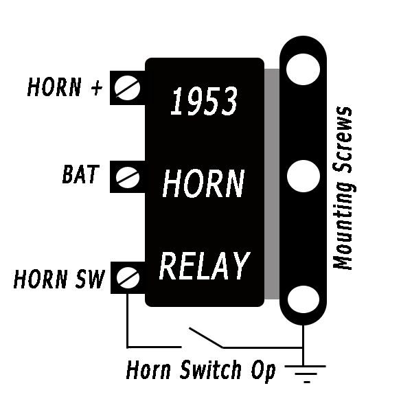
These two parts share the same two screws for mounting to the firewall. To test the relay for proper operation, I connected a 12 volt battery positive to the center terminal, the negative to one of the mounting screws or base. You can then take a jumper wire from the mounting screw or base to the bottom terminal temporarily to see if it 'clicks'. After using the contact cleaner I was able to get mine to reliably click each time. If you want to take it a step further, connect the horn to the top terminal and a jumper from the base of the horn to the base of the relay and try again. The nice part about the way they made this relay is, if you ever suspect your horn button on your steering wheel, you can jumper that bottom terminal like shown in the diagram and the horn should sound off. If it does, it IS the switch or wiring on the column.
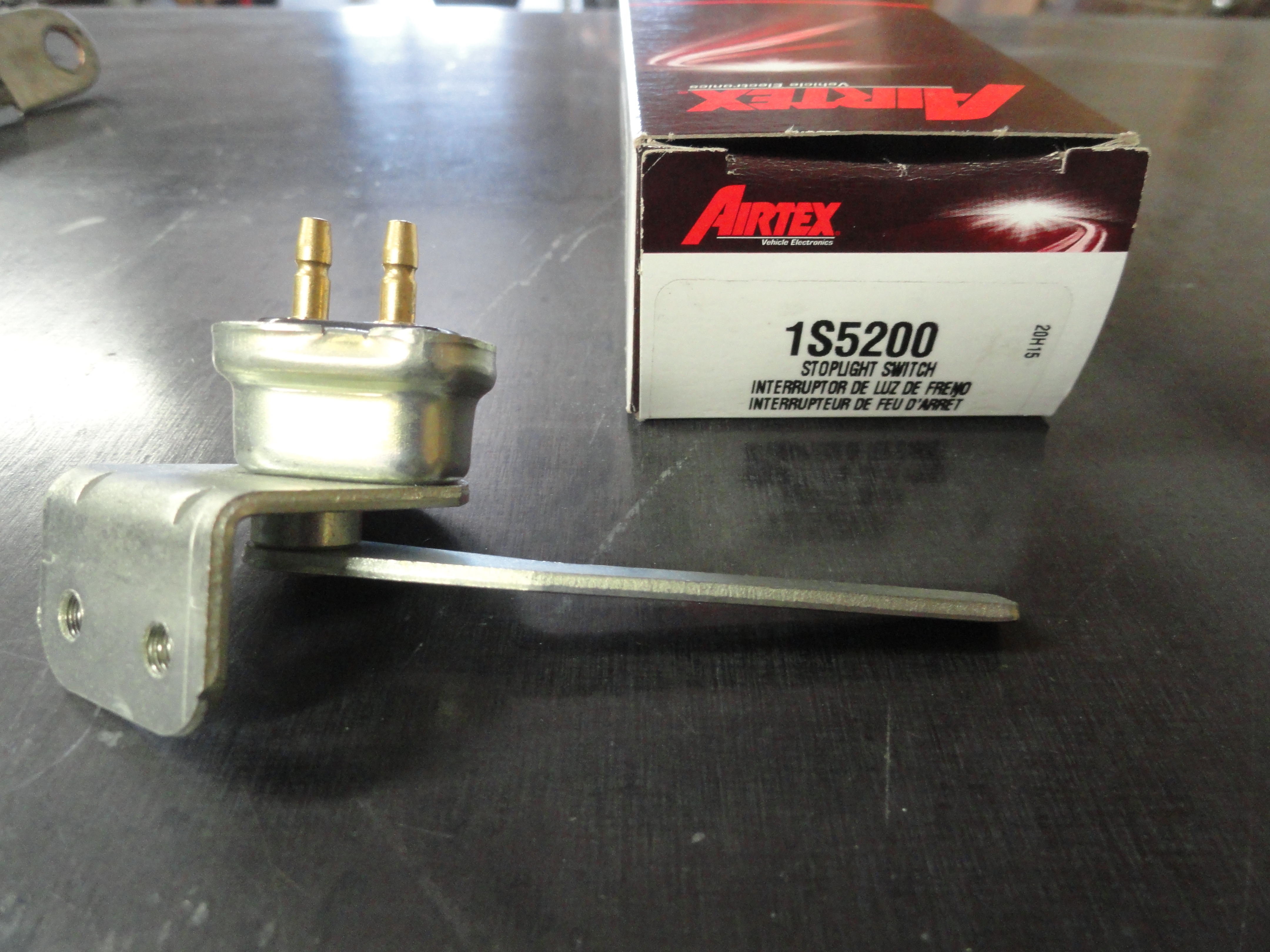
The brake light switch left is unique in that it doesn't matter which way you put the wires on. What does matter is that it is properly oriented and mounted to the firewall properly. Remove the switch from the firewall. Using a multimeter set to ohms or continuity, check to see if you get a short or zero ohms about halfway through the action of the switch. This should happen consistently and in the same place each time. Since this switch is sealed, it is probably best to just get a new switch if yours shows any indication of inconsistency. Replace the switch back on the firewall in its proper orientation.
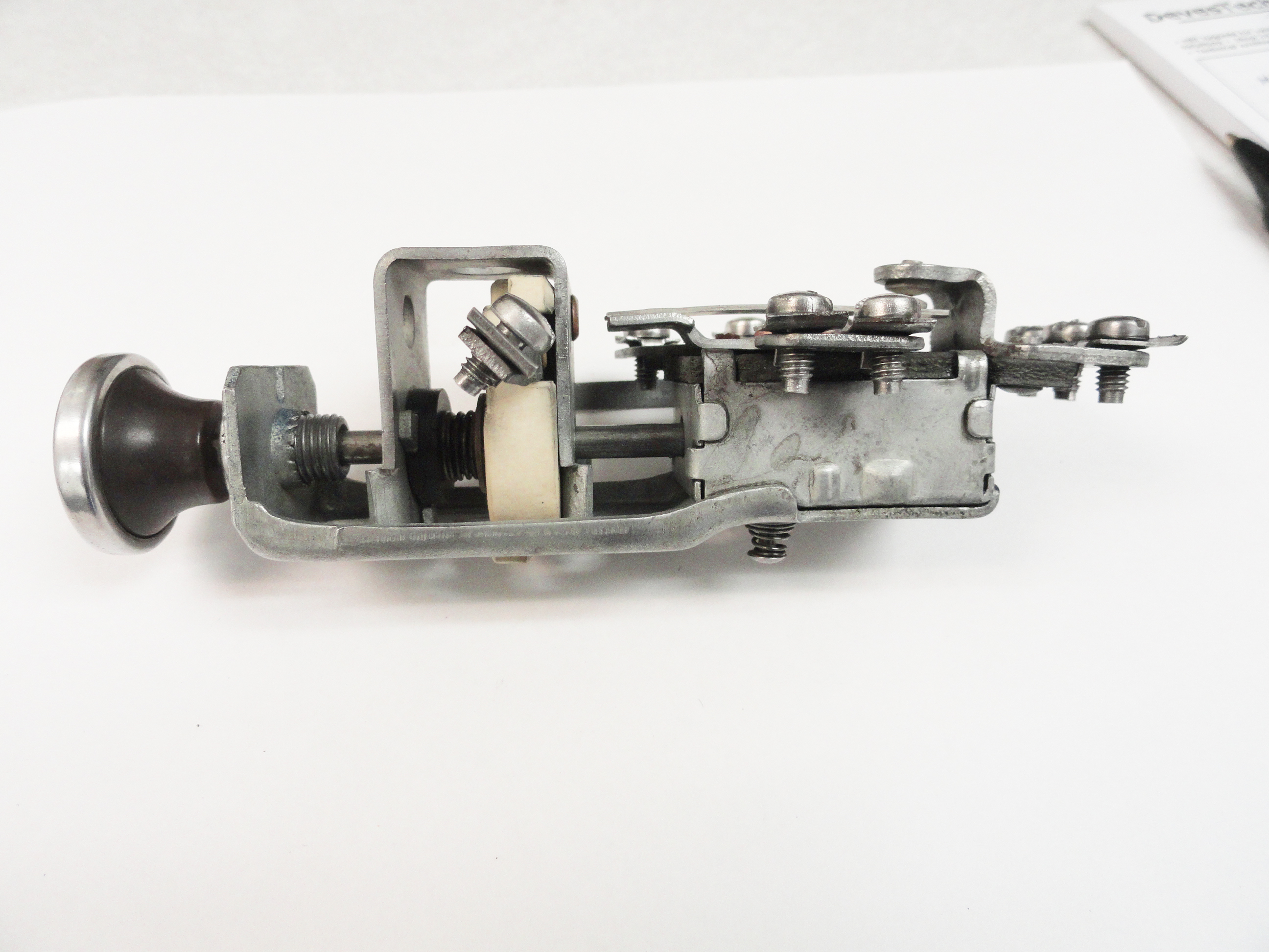
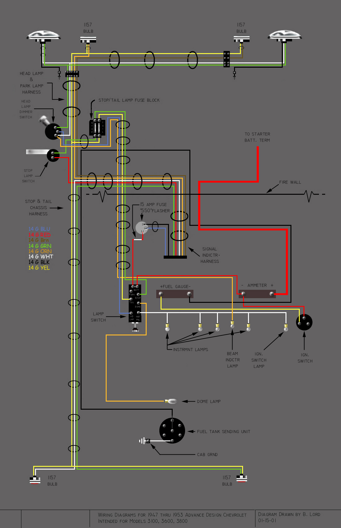
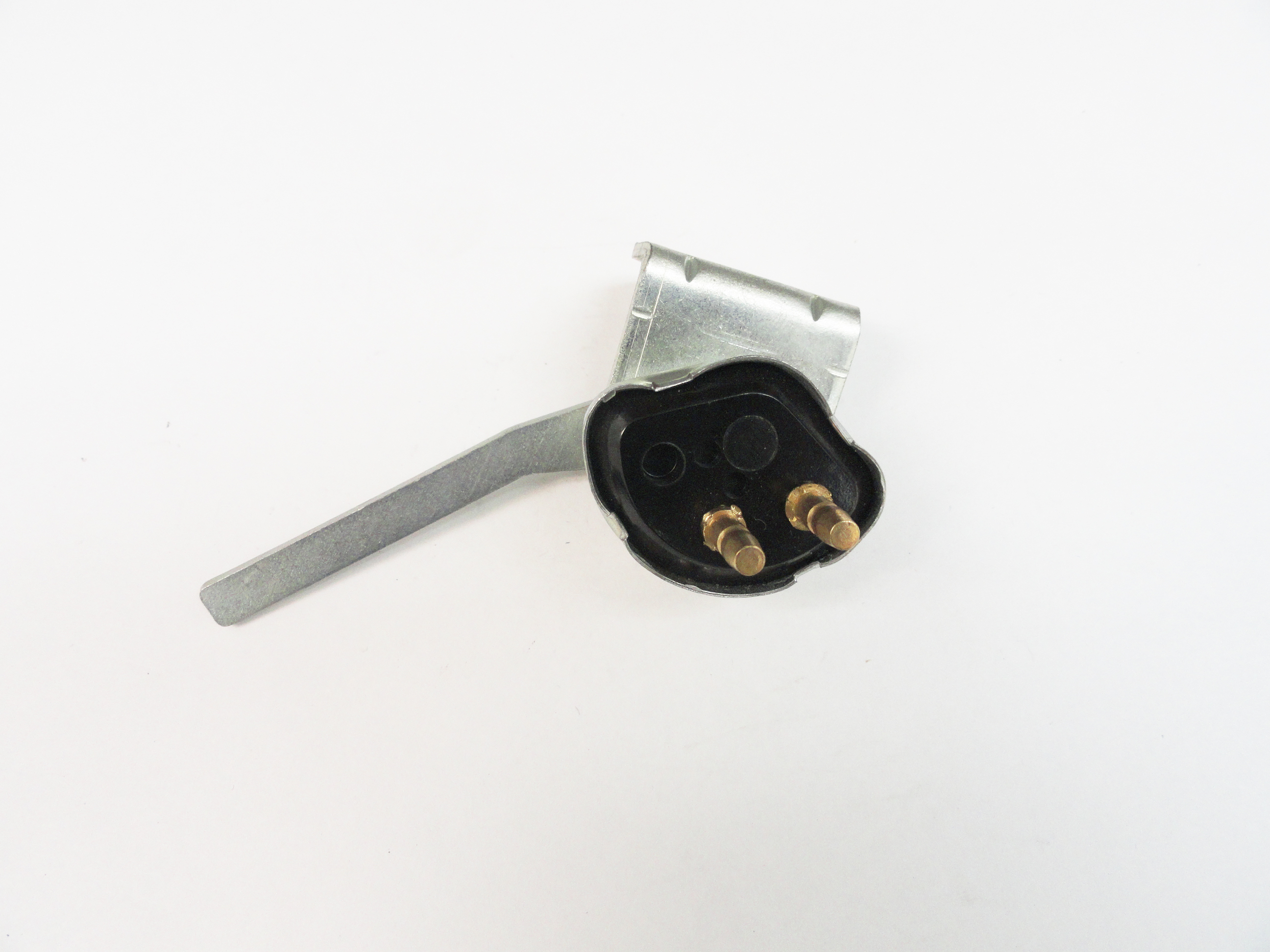
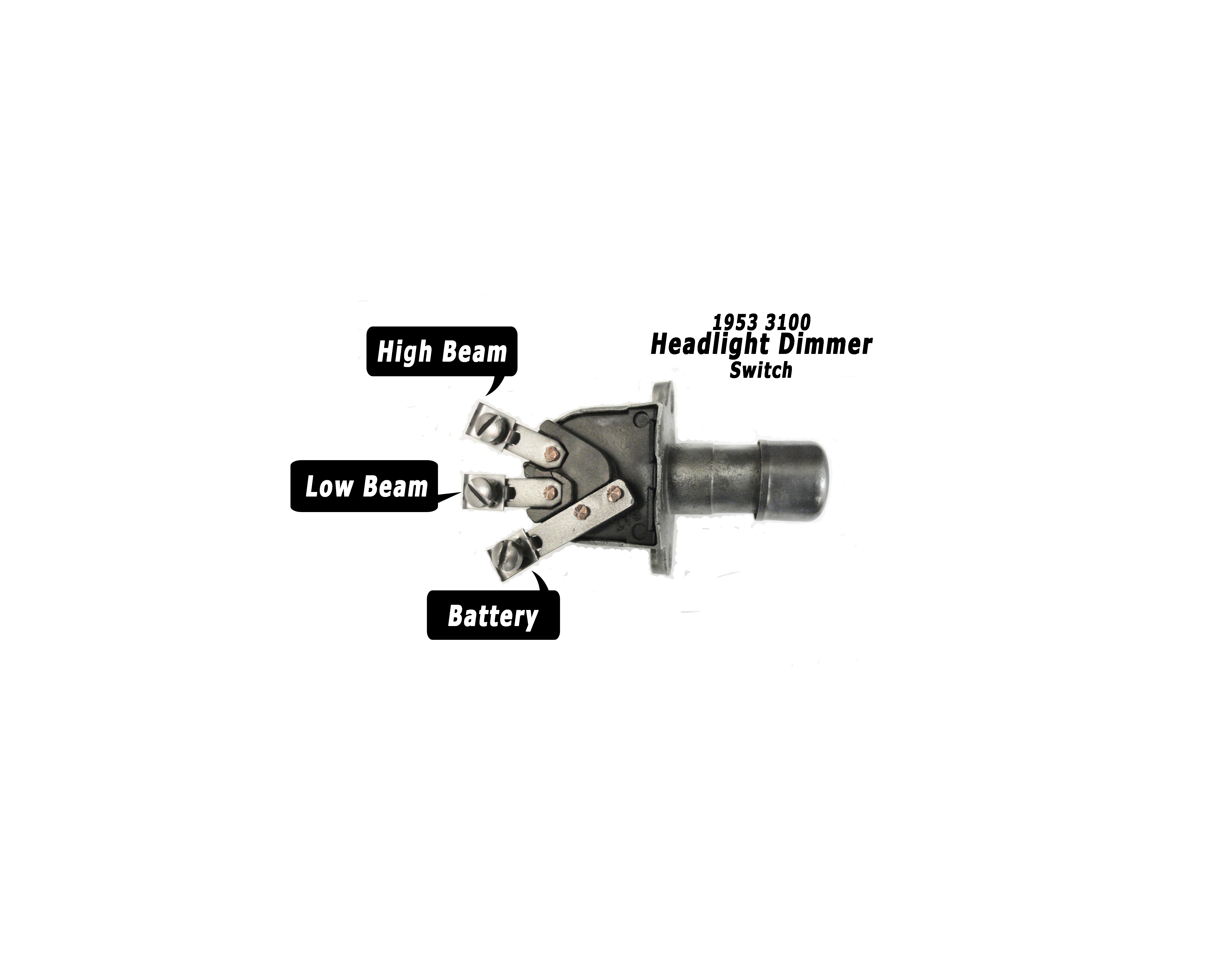
The Headlights Dimmer Switch takes a lot of abuse and could very well suffer from too much dirt in the switch. I spray this switch heavily with contact cleaner, then test to see if the switch opens and closes consistently and the springs pops it back up consistently. Using a multimeter, check the switch by putting one lead on the BAT terminal and the other on one of the contacts. Press the button to see if you get a clean zero ohms reading, then move your lead to the other contact to see if its working there. If anything isn't adding up, replace the switch. It is not worth it to have a problem with a relatively high amperage switch. The diagram will help you when it comes time to install the harness.
The Headlight switch in this vintage Chevy Truck is pretty central to the entire electrical system. In more modern vehicles, we have a fuse/terminal block which serves to provide two types of power. They are Switched and Unswitched. Switched power is provided by the Ignition Switch and Unswitched power is provided by the Headlight Switch. Remember, these are vintage vehicles and since they do not have terminal blocks for that purpose, it is essential that each accessory you add to your vehicle has an inline fuse.
An accessory is anything that requires power, either switched or unswitched. The Turn Signals, Heater, Electric Wiper System, etc, are considered accessories and require an inline fuse. Without the fuse, you are exposing your entire electrical system to potentially catastrophic damage. Always keep safety in mind when addressing electrical system issues. Fuse sizes are not based on the accessory as much as the wire that connects them. Of course both are kept in mind. An example is the Heater. The motor itself draws about 5 amps of current. The wiring for most of the vehicle is 14 gauge. The amp charts available online suggest a max of 15 amps for 14 gauge wire. Personally, I like to know a bit quicker when something that I know should only be putting out 5 amps is putting out 15, so I choose to use a 10 amp fuse. It's a very good idea to know exactly what your turn signals, electric wipers, heater, etc is rated at and then ensure your wiring is appropriate and you use the correct fuse.
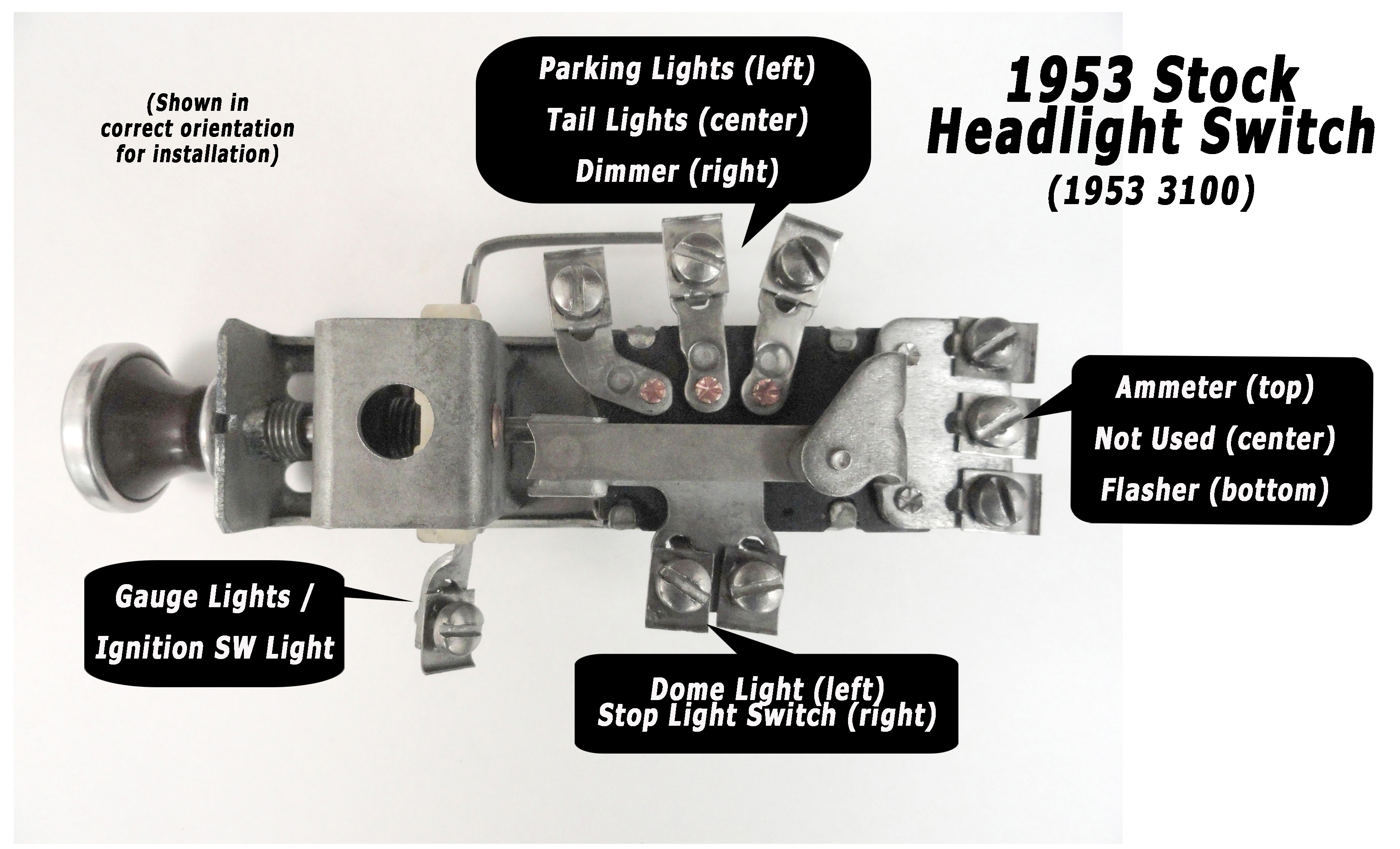
The headlight diagram (left) is your guide to wiring up the switch. The far end of the switch is the BATTERY terminals. All three of those end terminals are connected together and used for unswitched power. Since they are all tied together, it is acceptable to piggyback a new accessory if you run out of terminals.
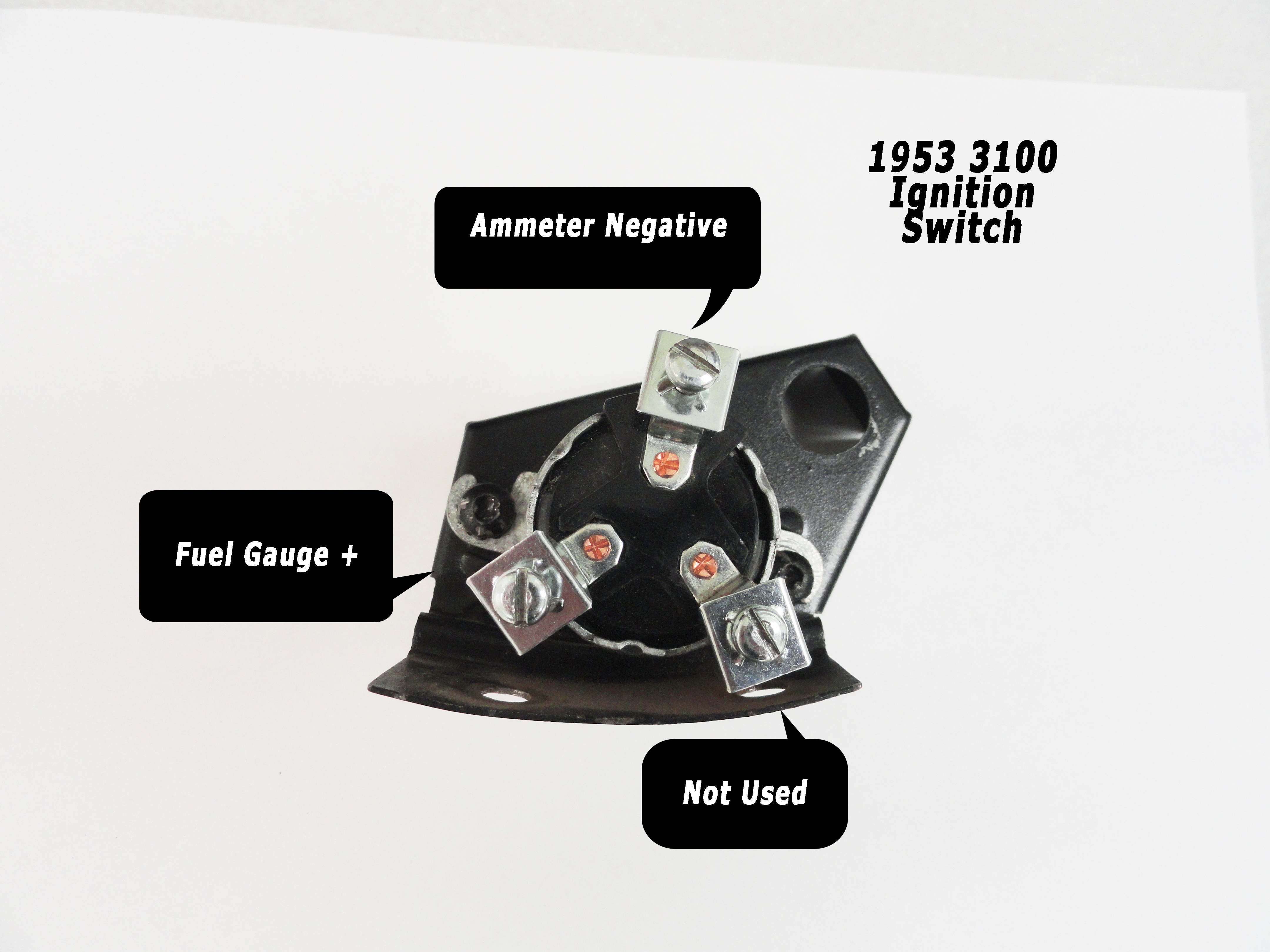
The Ignition Switch is what you use to connect Switched power. The only time switched power allows an accessory to be provided with electrical energy is when the ignition key is turned on. Ammeter Negative is the connection to the starter/battery directly. The one labeled Fuel Gauge is your switched terminal. So, anything that you require to be switched, you must stack on to that one terminal. This is generally not a problem since there are a limited number of accessories to begin with. If this becomes a problem you can always add a fuse/terminal block. It would not be hard to do, but most people do not find it necessary.
Remove and clean both switches. Use the contact cleaner liberally and then use a wire brush on the terminals. There should be no corrosion present anywhere. After cleaning with the contact spray, your gauge lights will dim smoothly and everything will work much better. Reinstall the Headlight Switch making sure the terminals are facing the gauges giving you great accessibility when it comes time to wire the switch. Leave the ignition switch out for now. It is very hard to wire with it in place, so we will install it after it is properly wired.
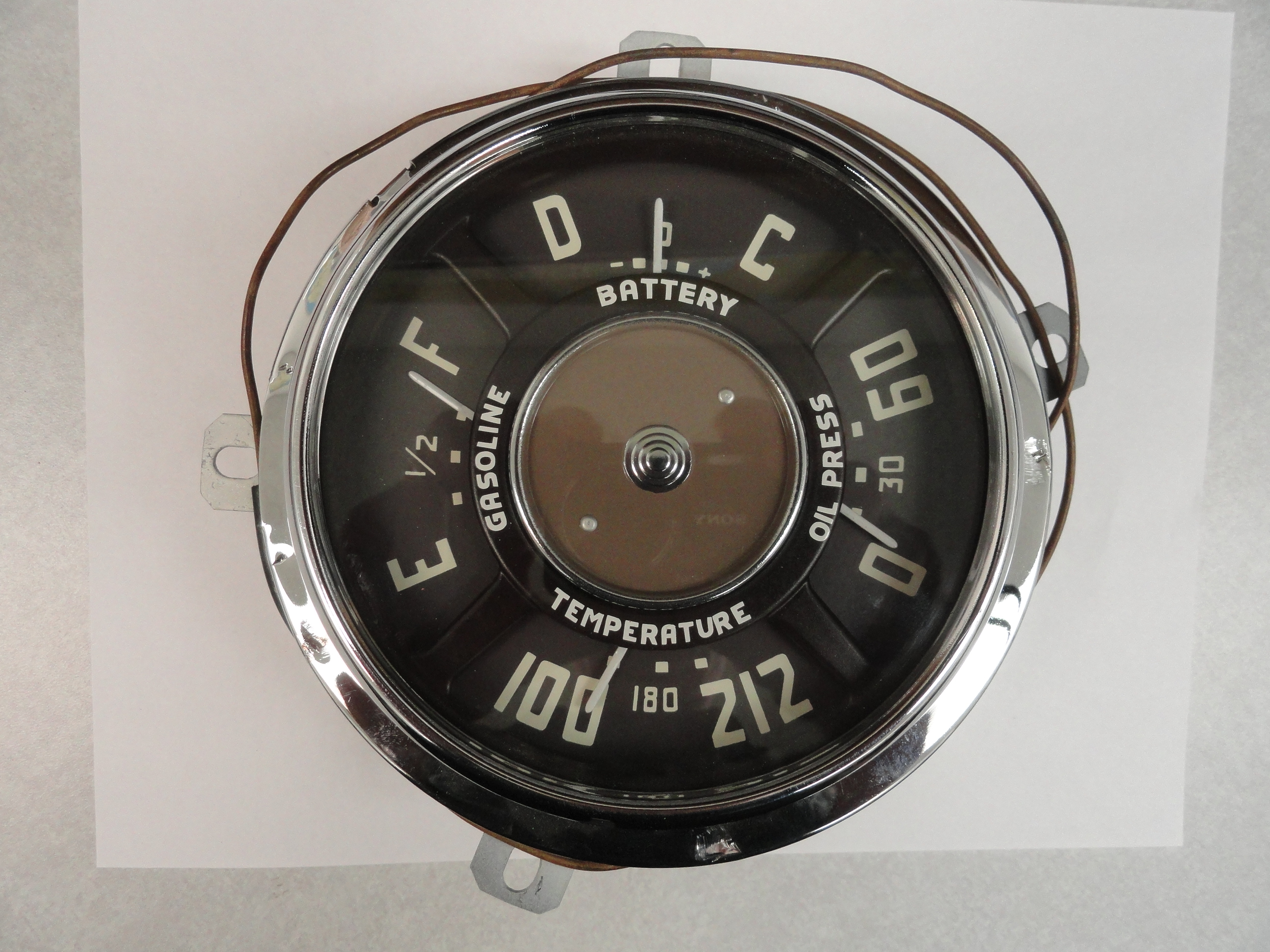
The gauge clusters are held in by 4 nuts that are screwed onto studs that are placed appropriately for holding the cluster in place. For us older guys, this arrangement can be really difficult, however, the key is to just sit on the bench seat and reach under the dash and feel the studs/nuts and with a nut driver just feel your way around to get them out blind. Remove the 4 nuts and there is no real worry about the gauges falling out the back. The reason for this is because there are water temp and oil pressure hard lines going to it.
The next step is to remove the water temperature sensor from the engine's Head. The sensor is screwed into an adapter that is placed on the drivers side close to the firewall. It has a copper line going to it. The reason we are removing this is to get the gauge cluster completely out of the truck so we can do some refurbishment to the gauge cluster. New chrome bezel, glass, decals and even new gauges parts are available if needed. If you do not need any servicing of your gauges, no need to remove the water temperature sensor.
Carefully remove the old 4 hole grommet and remove the sensor from the Head. It is advised to lower the water level sufficiently so you do not have water spurting out of your engines Head. Drain the Radiator by about half and this will ensure you do not have a gusher on your hands. Thread the sensor back through the grommet hole being careful to keep the line from over bending or crushing. A loose loop about the circumference of the gauge cluster is a fine way to keep that line from crushing or bending.
The next step is to remove the Oil Pressure line. This line is simply a piece of copper tubing with the correct ends on them for connection. It is a good idea at this time to remove it and make sure the line is serviceable. Blow through it to ensure there are no obstructions. To do this, remove the line from the engine near the drivers side bottom. Sometimes it is on the end of a 1/8" NPT Tee connection. By now, your gauge cluster should be very accessible so it will be easy to see the oil pressure line and disconnect with a small wrench. We are removing these hard lines for easier accessibility for connecting the wiring. It is best to start your harness install with the gauges on the floor of the vehicle.
The Speedometer Cluster is easier and requires loosening the threaded speedometer cable and then just pulling three bulb fixtures out of the back. Once you have it out, check the cable for serviceability. Remove it at the transmission and spin it by hand. It should move very freely with very little resistance. It is then a good idea to add grease in the grease cavity on each end of the cable. Install the new Speedometer Cable Firewall Grommet by cutting the grommet from the hole to the outer edge with a sharp Exacto Knife to get the cable back in. Do not be tempted to install this cluster just yet. It is much easier for access to the other cluster if left to be installed last. Just like the other cluster, maybe now is a good time for new gauge parts or any maintenance you may feel is necessary.
Next, remove all the wires and bulb fixtures that are connected. Do not worry about wire placement for the new harness. That will all be taken care of with the documentation you get with the harness. At this point, it is also okay to remove the main harness to this point. All headlight wiring and everything to the gauges can now be cut out in any fashion you wish. The only thing to be careful of regarding removal of the old wiring is to note the routing. Especially how the wires go down from the lower firewall and to the back of the truck. Also, read the next section before cutting the dome light wire!
The Dome Light is next. The wire from the Dome Light to the Headlight Switch is routed through the drivers side A-Pillar. This is a particular pain to do unless you know the secret. The secret is to attach the new wire to the old wire and fish it through the pillar. As it stands now that the Headlight switch has nothing on it, you can locate the wire that is very close to the switch and is routed UP. It will be easy to spot. Cut the terminal end off that wire and have it ready so when you get to that point, you can use electrical tape to tape the new wire to the end of the old wire to pull the new wire up the pillar. You want to be very slim about it. Do not make a huge wad of wire and electrical tape because the A pillar is surprisingly narrow and you can bind it pretty easy. If you do end up breaking it and fail to get it into place, try again with safety wire.
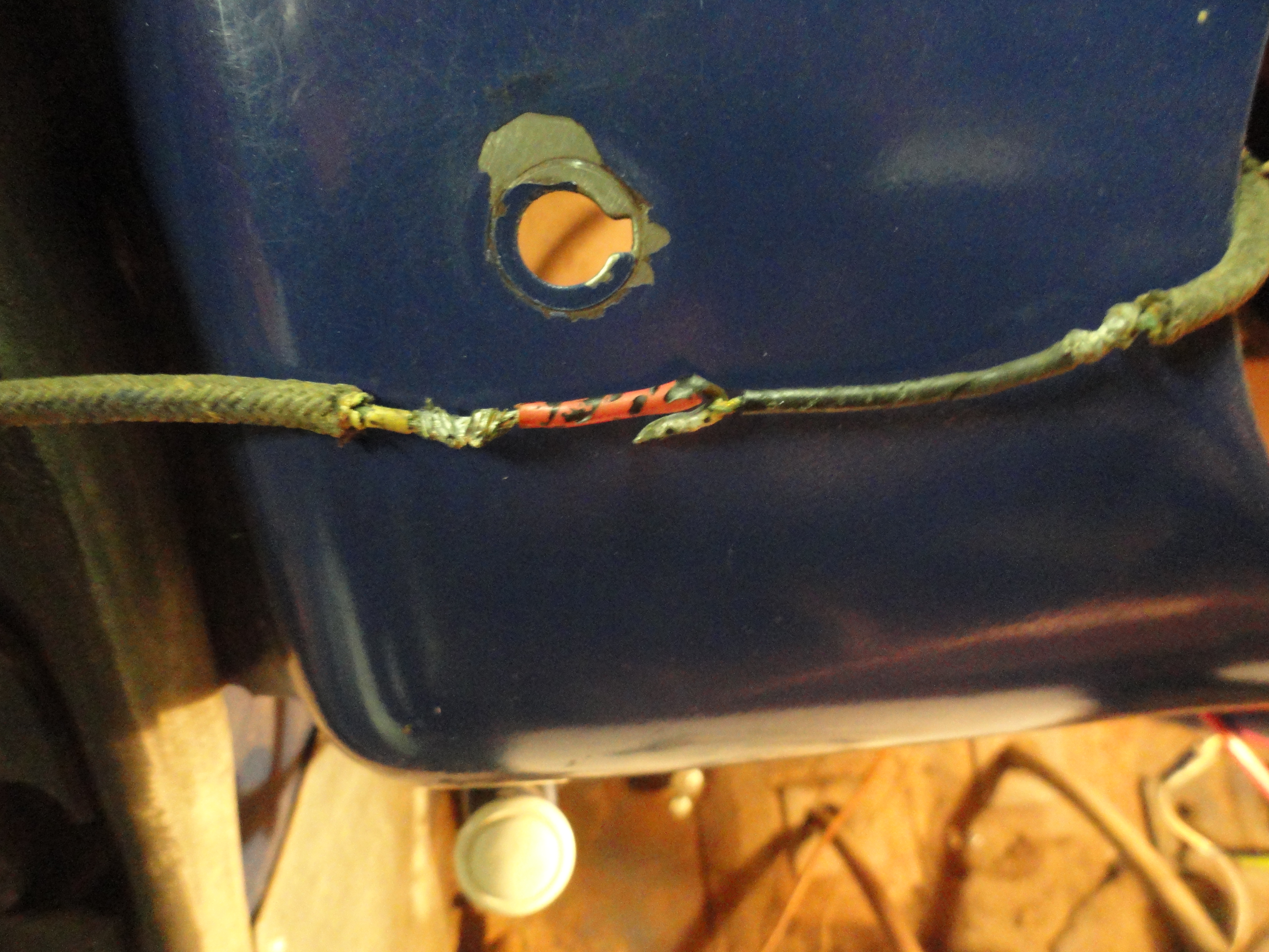
The Dome Light comes off with a few screws and it's a good time to look it over carefully. In this case there was good reason. The original cloth wiring was present and in very dire shape. Check out the picture on the left. There is no doubt a shorting hazard exists. The problem is, upon close investigation, the cloth wire goes directly to the bulb. A soldered end fashioned for a bulb contact was all there was to it. I fixed this by removing the small copper bulb contact from one of the old harness sockets. I pried it open to receive a new wire then crimped it on and threaded the wire through. The switch wires were just as bad, so they were replaced as well. I left a 12 inch lead wire with a barrel connector on the end to attach to the new harness wire. After doing a little maintenance on the dome light, put it back where you found it. It's ready to accept the new harness without surprises. You will also notice along the headliner lip is a few wire clips. You want to set the new wire back into those clips to aid in proper routing. A picture of the correct clip is in the picture archive at the bottom of this article.
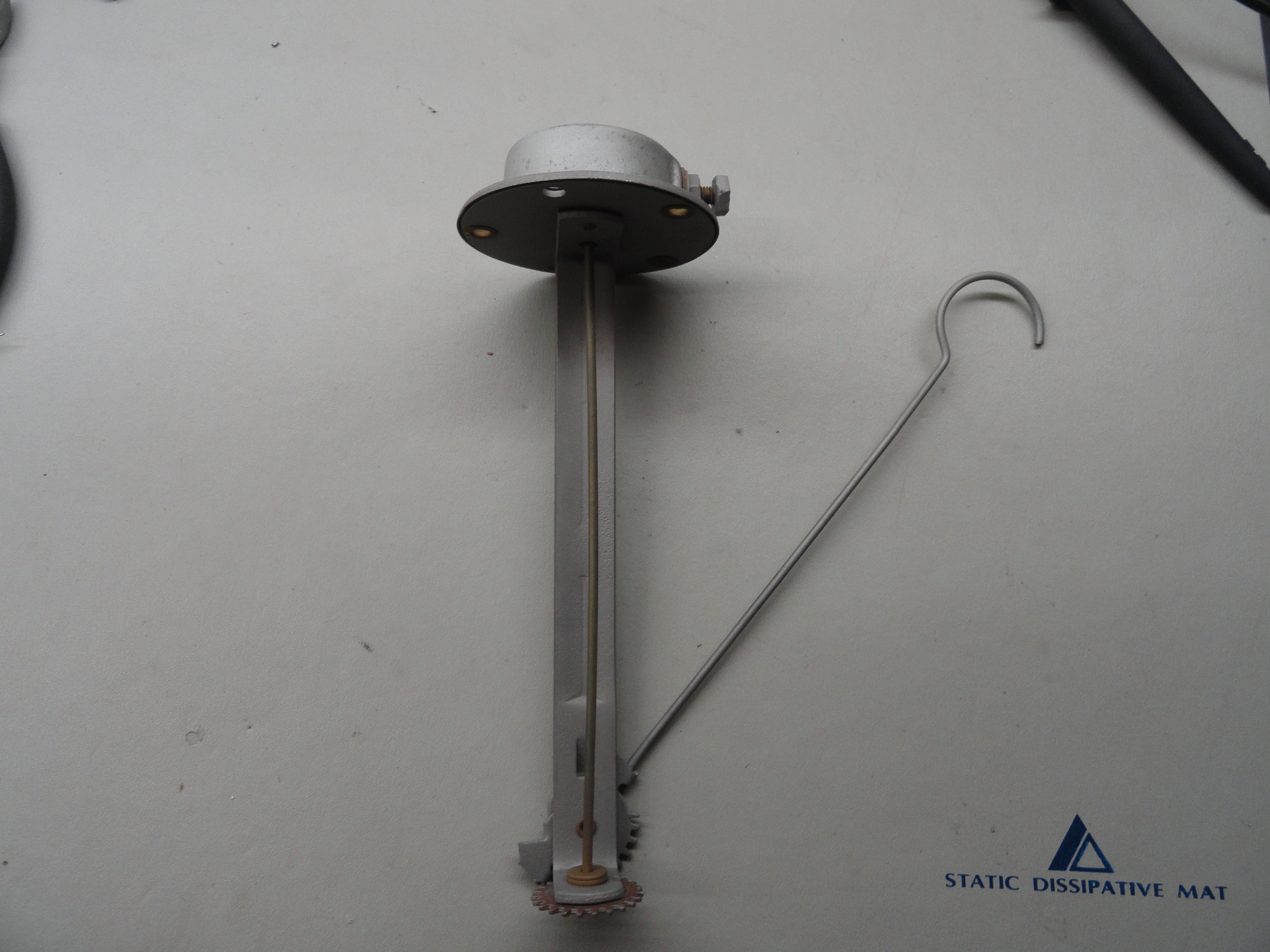
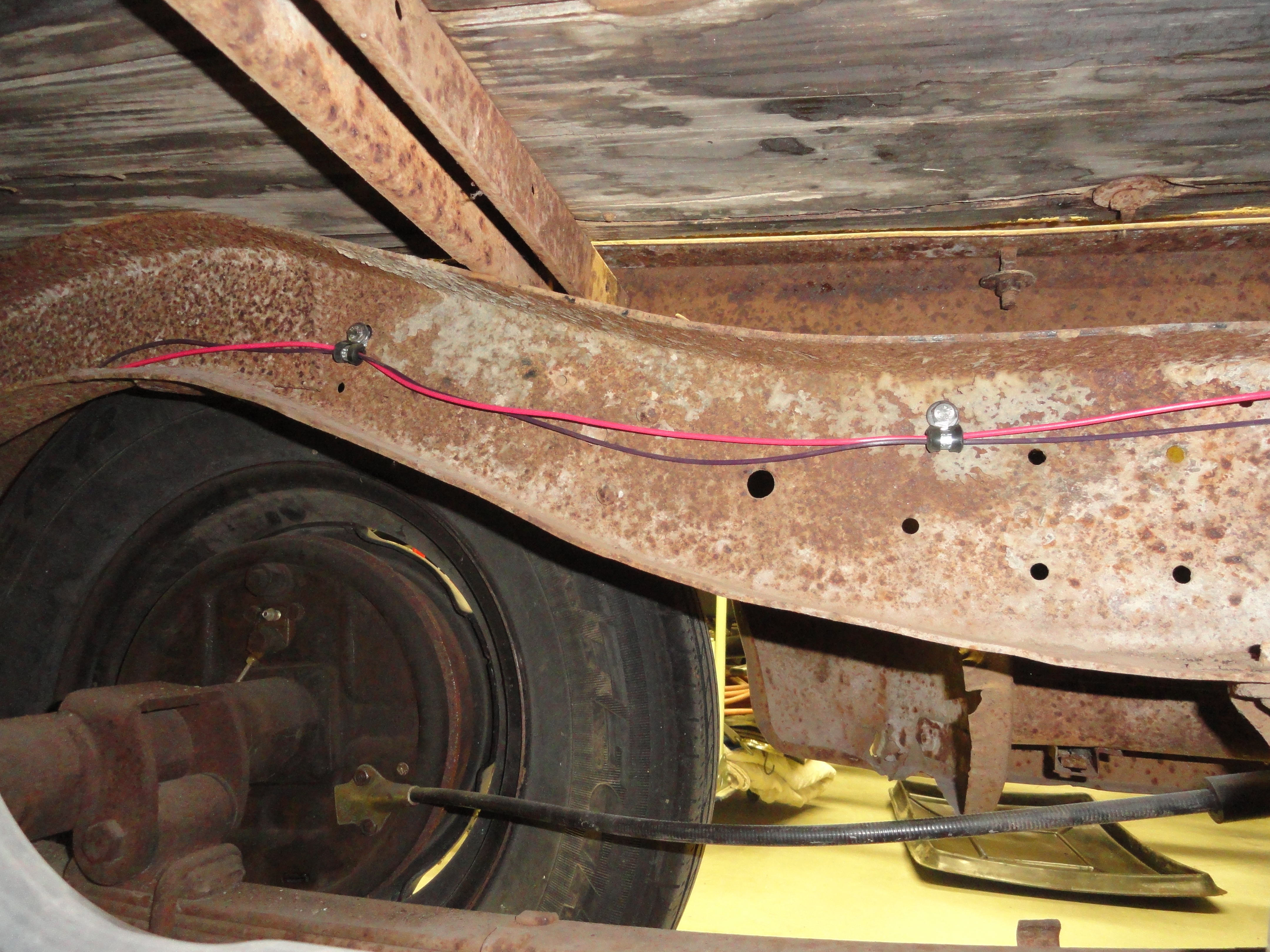
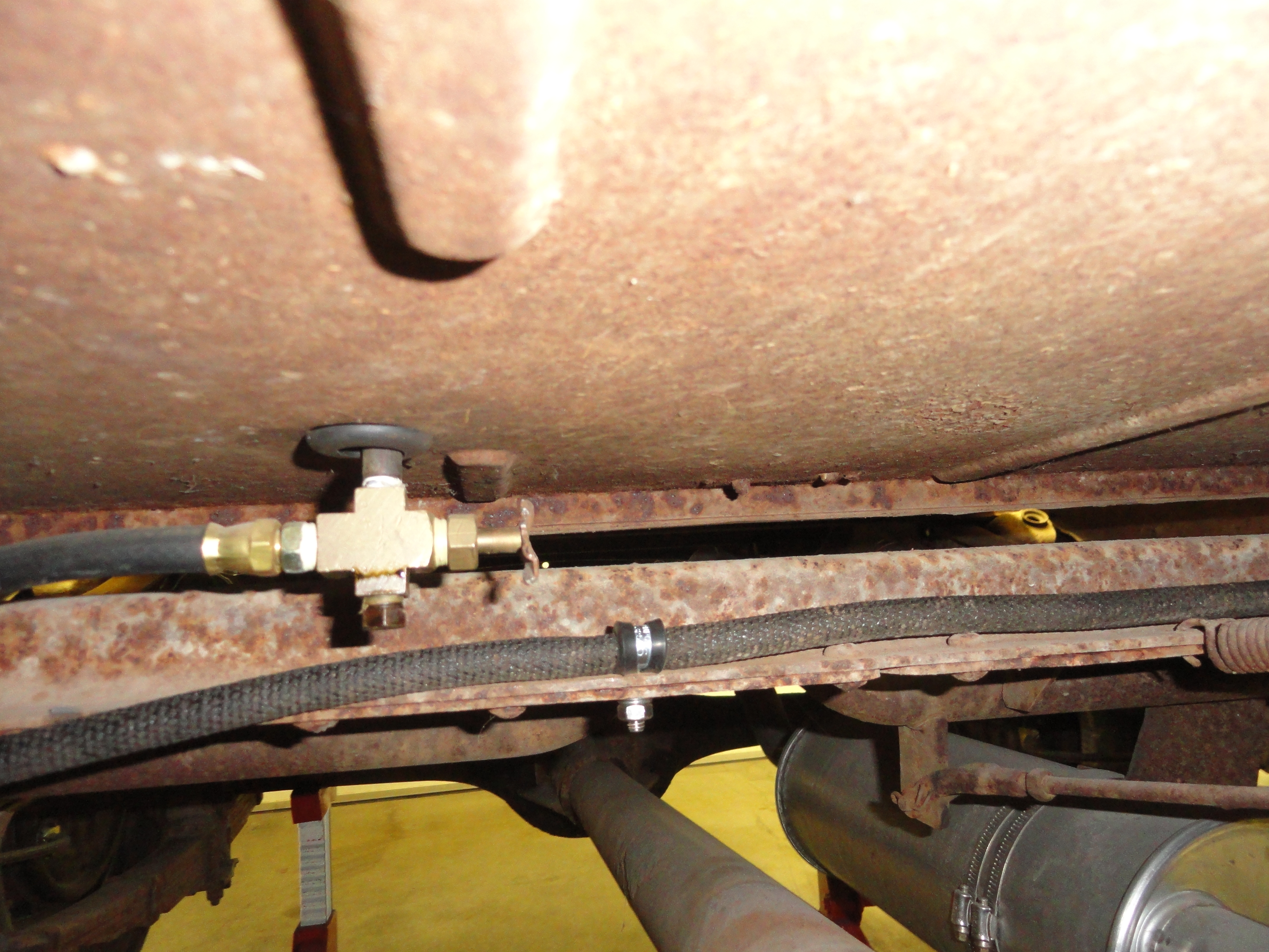
In keeping with the plan to move from front to back, the fuel sender is next. The wire for the sending unit is routed from the firewall down to the drivers side frame rail and to a grommet near the center of the cab rearward underneath. It follows the same initial path as the taillight wiring. There is only one wire. It is not hard to feed that wire up to the sending unit from underneath when the time comes. Remove the back of your bench seat to access the sending unit. It is mounted to the top of the gas tank with 6 screws. Pay attention to how it is oriented in the tank and be sure to put it back the way you found it. The arm needs to freely swing, so a 90 degree turn when installing could be a problem. The reason we are taking it out is because it should be tested before the new wiring is installed. I know it may have worked before, but a simple test will tell you if it needs a proper cleaning. With it out, put the multimeter on it, one lead to the center terminal, the other to the side of the sender, just to get a good ground. With your multimeter on Ohms, move the arm up and down. You should get between 0 and 30 Ohms. (0=empty, 30=full). The thing is, we do not want any hiccups in the reading. It should smoothly go up and down the scale with no erroneous numbers. If you are getting hiccups, just use the electrical contact spray and spray it really good at the resistor array. With it clean, you will notice a much smoother reading. Reinstall the way you found it awaiting the new harness.
The taillights take a left turn for the passenger side at the front side of the rear crossmember. What I like to do, and I realize this is not original and I do not care, is to use those rubber inserted Adel Clamps and place them about every two feet apart wherever I can find a bolt hole that isn't used. I used a total of 12 of them. 5 were 3/8" Adel Clamps and the rest were 1/4". I also used stainless steel 1/4" hardware. This keeps the wires safe and provides for a nice clean installation.
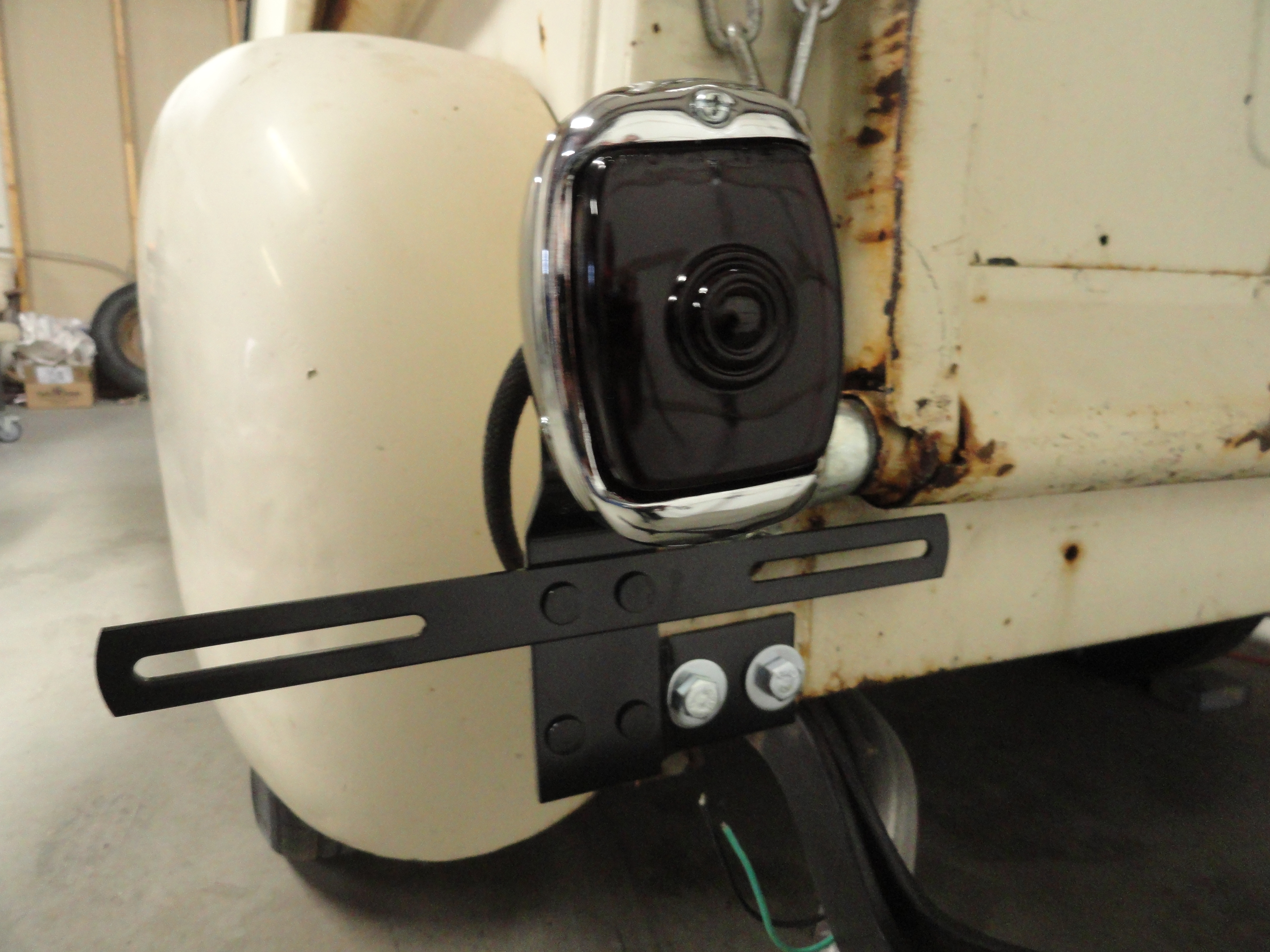
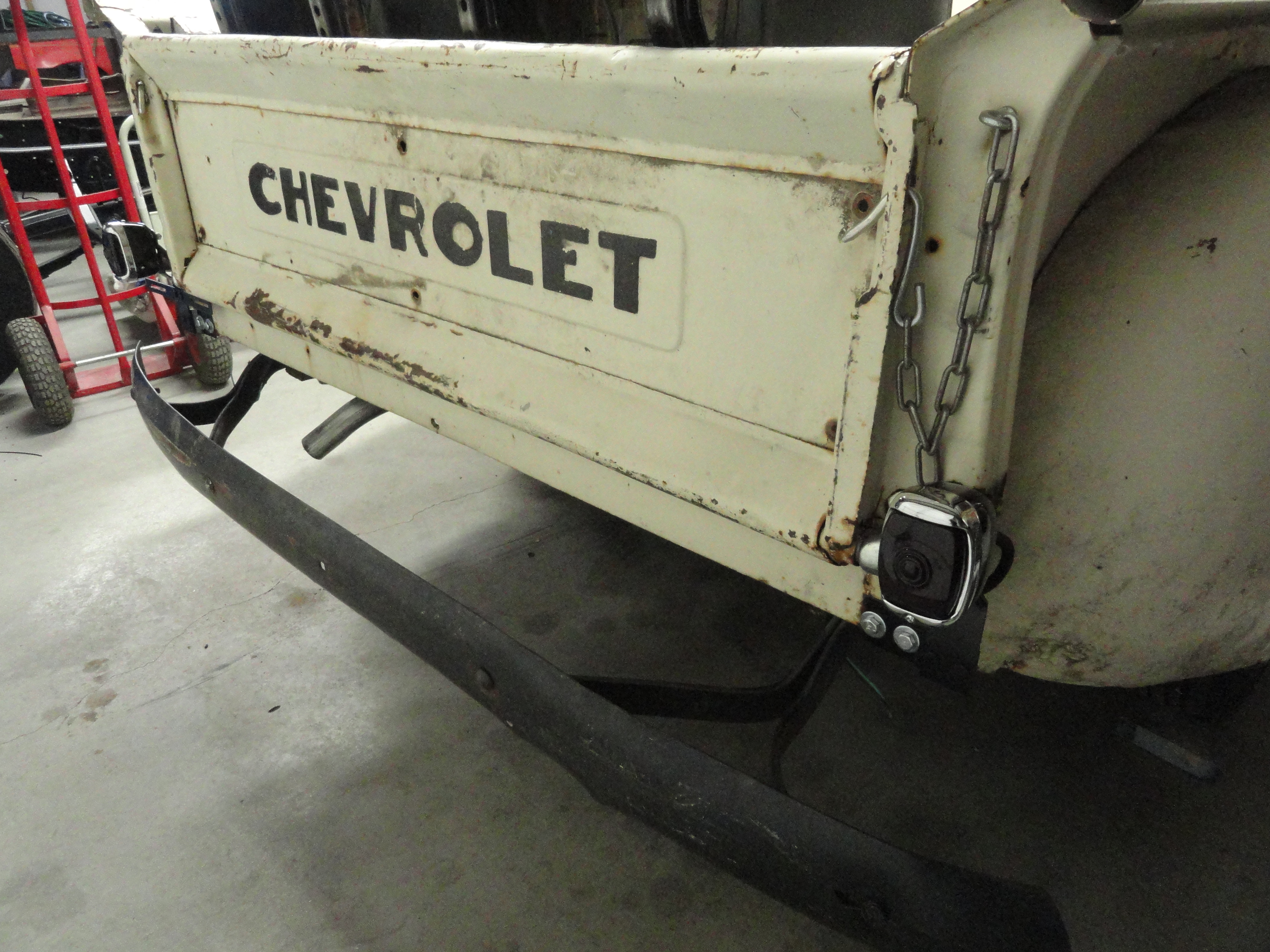
The taillights may be fine the way they are, but in my case, I had none. I ordered new ones and then put the proper 12 volt bulbs in. There are two single filament bulbs in each fixture. It is important to know which wire goes to the brake and which wire goes to the tail lights. You can test the fixture with a multimeter to tell which one is which. You need to know this so when you install the new harness, the most dominant light (the one that sits in the middle of the lens) is the brake light. Mark the wires so you know when installing the harness which one is which.
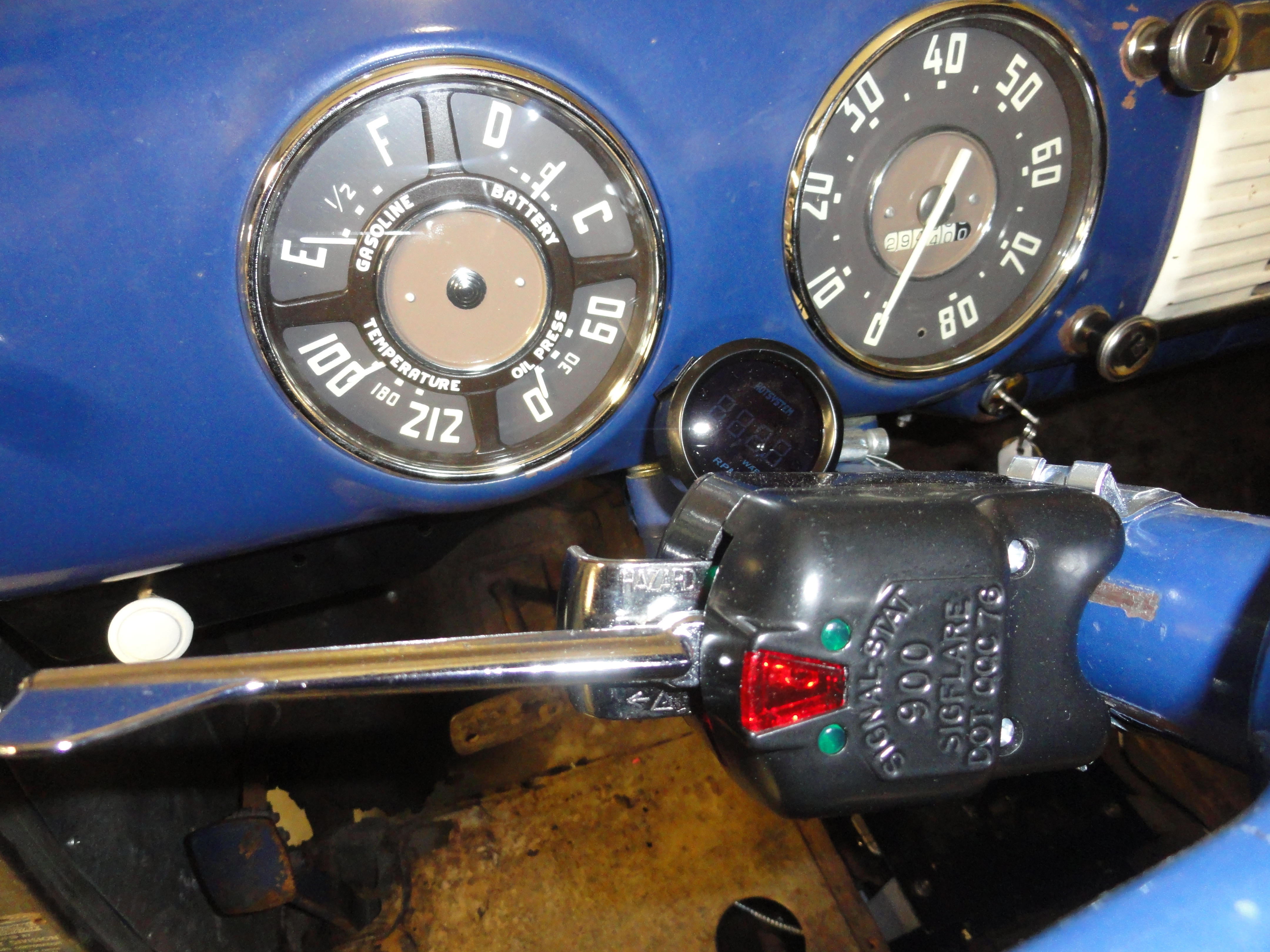
Chances are, the turn signal switch you have is not correct for this harness. To find out, check to see how many wires you have going to the turn signals. My old switch has two. There is the flasher wire, and battery and ground, but just two for signaling a turn. This arrangement will not work with our new wiring harness and we are happy about it! Why? Because with this new harness, there is no need for extra fixtures for turn signals. The park lights are modified for dual filament bulbs and the rears are good because they have two bulbs. This unfortunately requires a 7 wire turn signal switch. So, if you have a 7 wire switch, you are good to go. If not, there is a very nice switch that is still in production today. They are used for large trucks and vintage vehicles!
Enter the SignalStat 900. I did a search for this switch and found one for $42 on Ebay. I hear they are very popular and from the look and feel of the switch, very high quality. This switch requires a Number 263 Turn Signal Flasher which is a special flasher used for this switch. There is also an LED capable version available. The new harness's instructions will have a nice explanation of where each wire goes and enough wire placed in the proper place for connection. The Switch also has wiring and installation instructions. No way to lose!
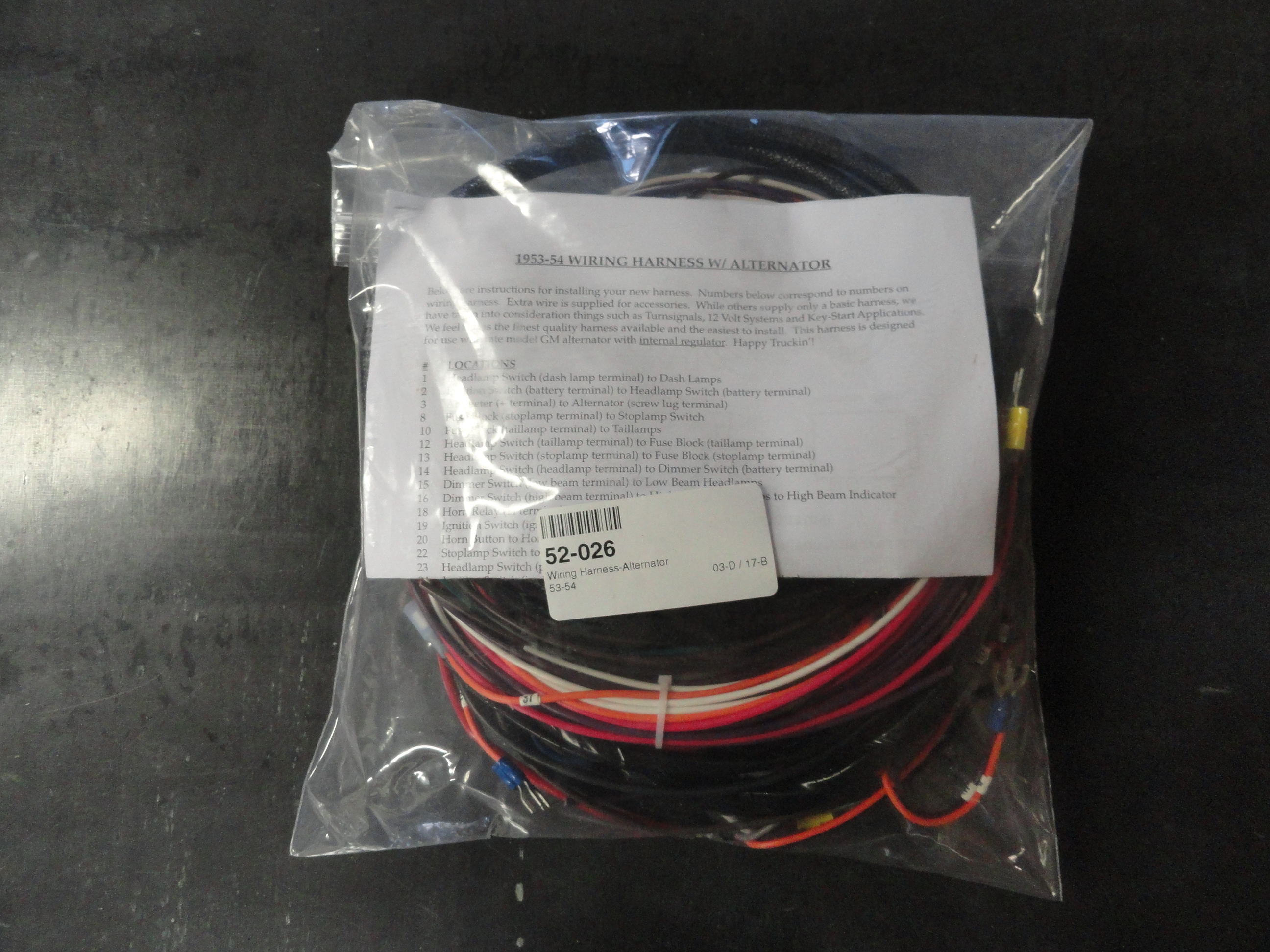
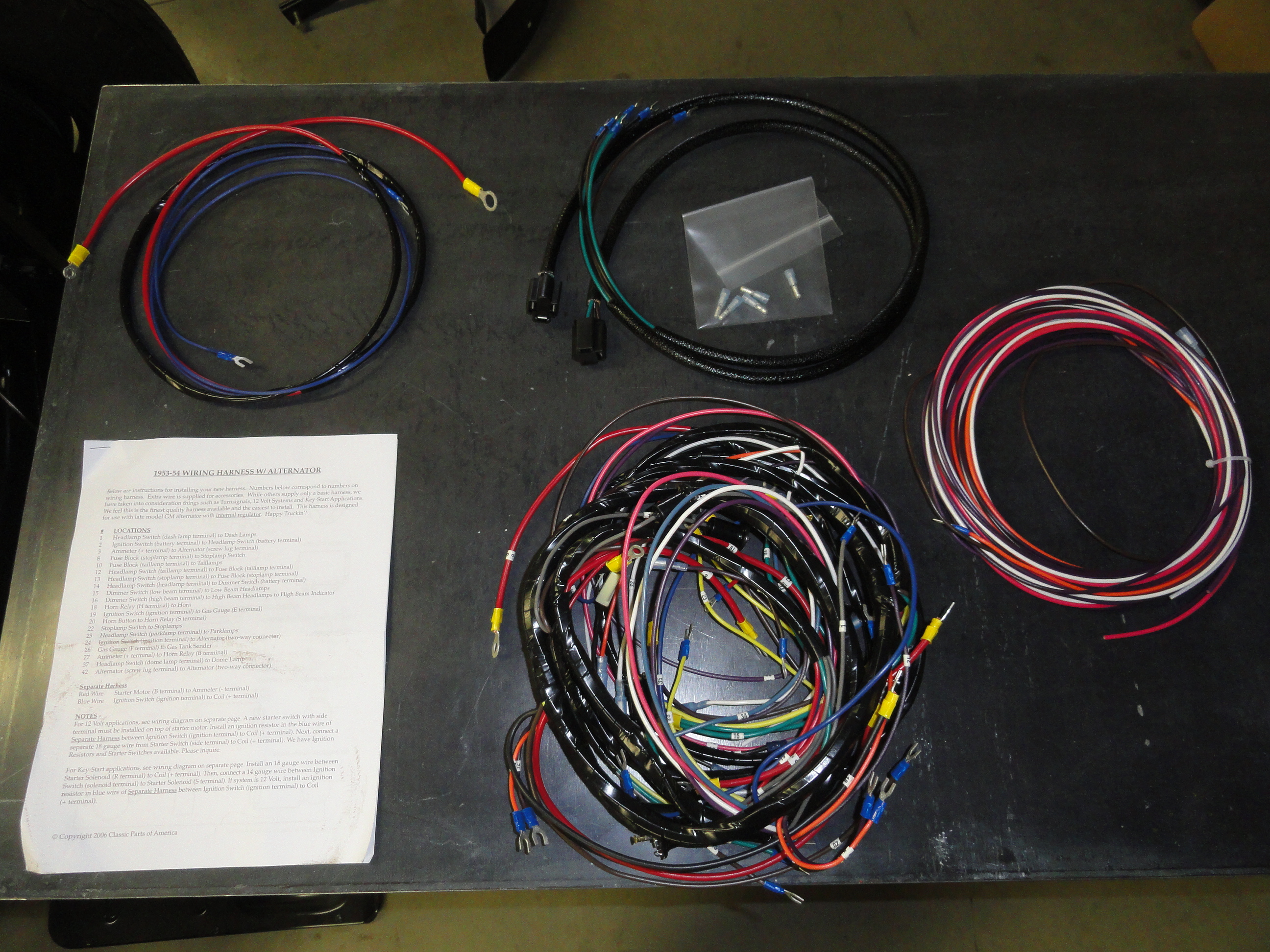
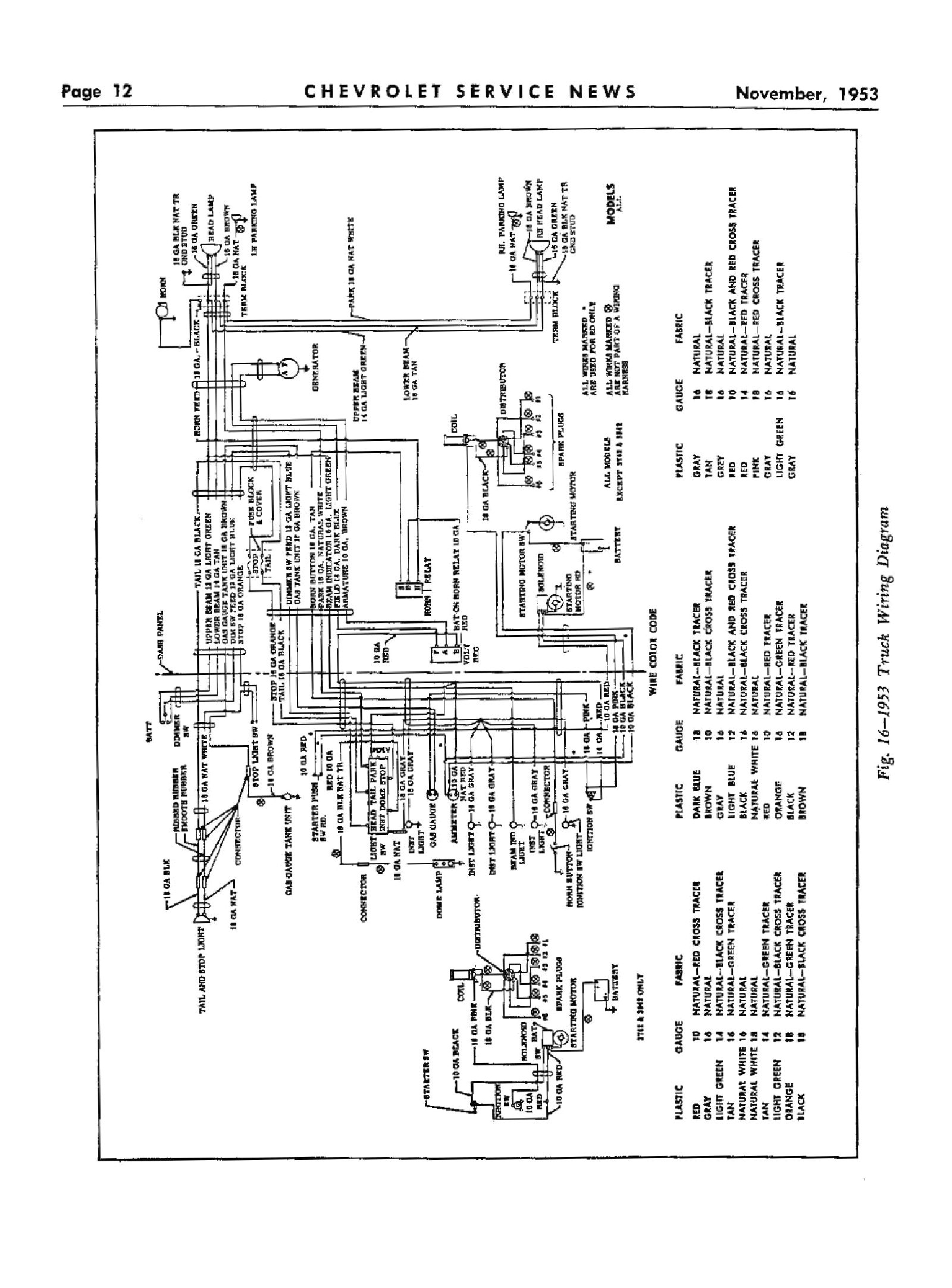
Let's take a look at the new harness. Pretty no frills and comes in a plastic bag. Opening the bag, we see two sheets of paper. Surprisingly, no wiring diagram! I spent the few days building up the courage to start on this project wondering why no wiring diagram. It just made no sense! So with that thought in your head, let's proceed and then later you can ask yourself that question after the install! Remember, if you really think you need one, you can always look at the one in the pictures in the archive below. The first page is the one you will find the most important. The second page is helpful for knowledge of the turn signal and extra wires. The back of the first page has good drawings that help in connecting the wires. Without further judgment, let's begin. At the end of this article, I will critique the package.
The package has the following contents:
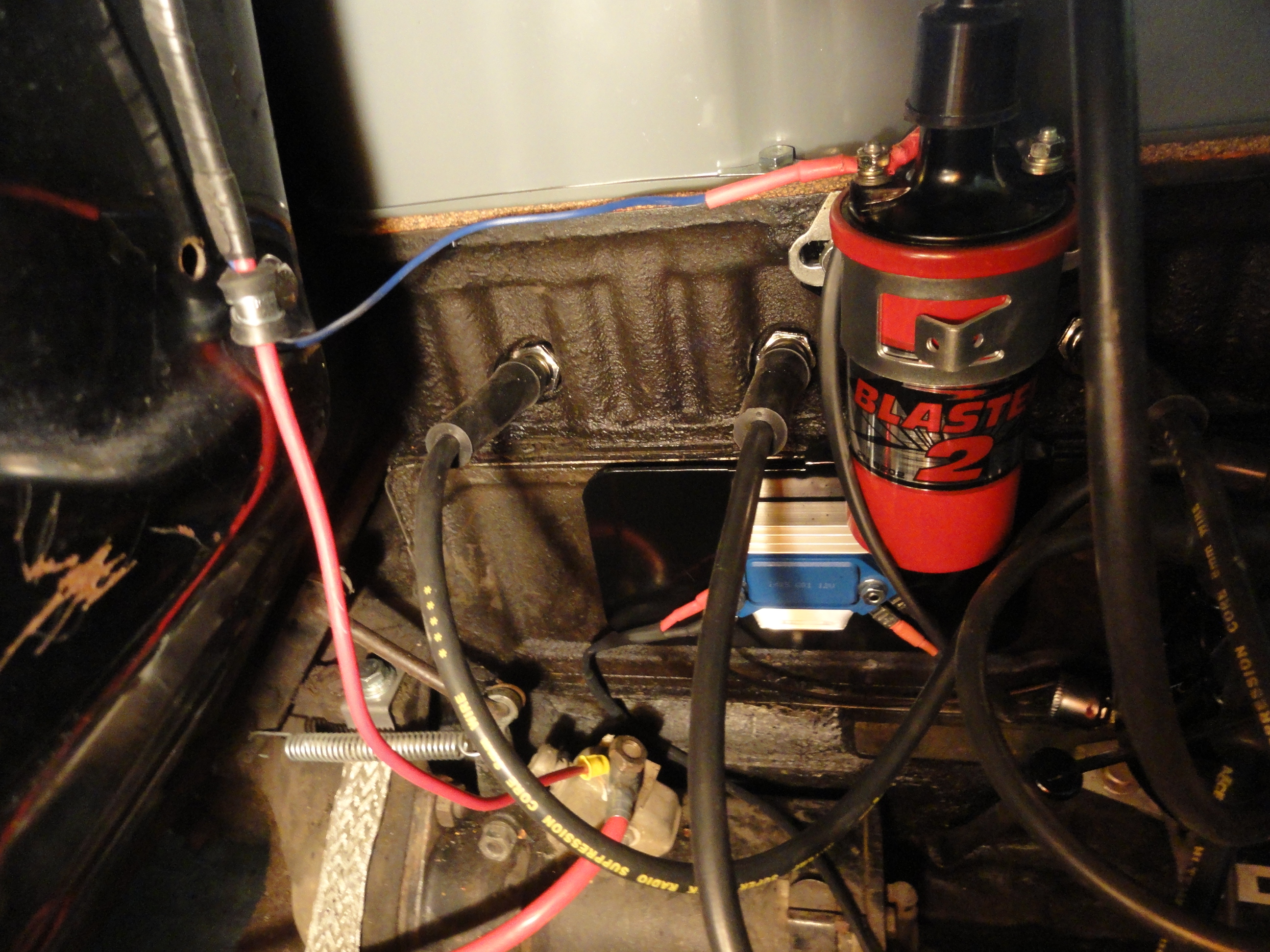
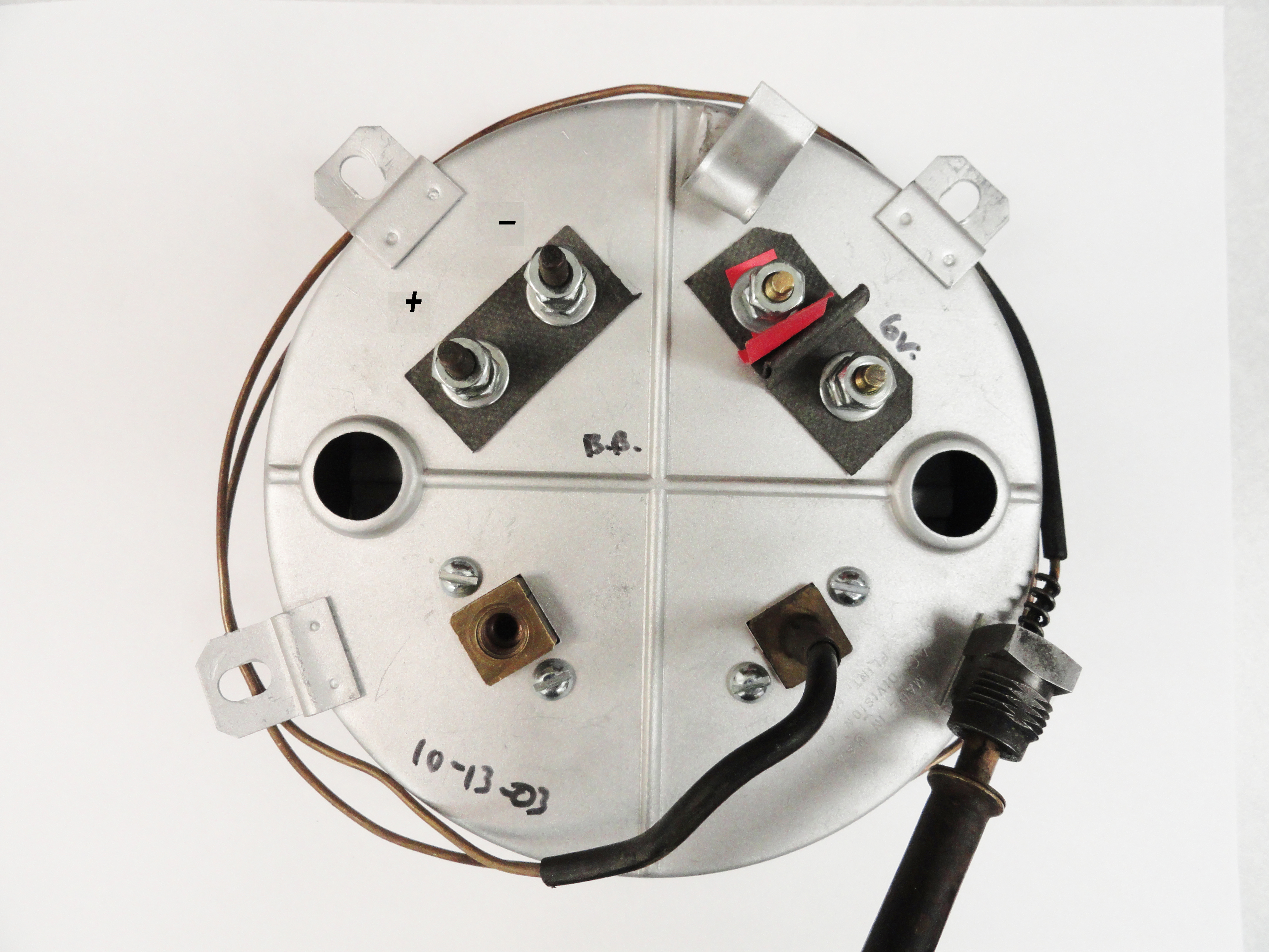
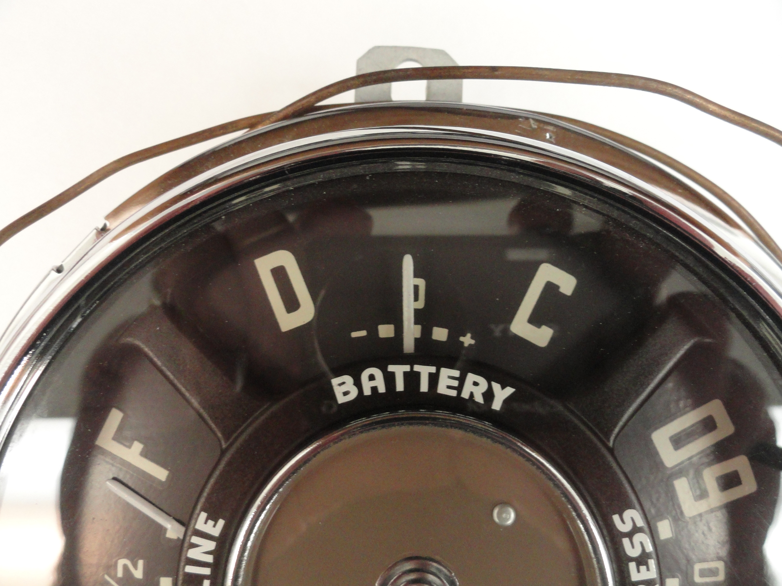
Let's clear out everything in the Harness package other than the Main Harness First. Start with the Starter/Battery and Ignition Bundle. This is two wires with electrical tape holding them together. This will go through the Starter/Ignition Grommet on the Firewall. Place the wires with the smaller terminals through the grommet and into the firewall. Secure the grommet and route the wires across the firewall as shown. Connect the thicker Red wire to the Main Battery Terminal on the Starter. This will provide your entire electrical system with Battery Positive. Connect the other end to the Ammeter's Negative Terminal. To end the confusion once and for all as to which is Negative and which is Ammeter Positive, use the markings on the face of the gauge. The Discharge (-) Terminal is your Ammeter Negative.
The Ignition wire that accompanies the above wire goes to the Ignition Coil (+) side. This wiring harness is for 6 or 12 volts, but the instructions cover 6 volt OR 12 volt with Electronic Ignition. If you have a stock 12 volt points system and you want a bypass wire with ballast resistor, follow the instructions provided with the harness. In our case, our system is our very own HEI system. I found this bundle could have had another 10 inches or so of electrical tape wrapped so I just extended it myself. Use Adel clamps with rubber inserts to secure these areas. You will need about 20 of these 3/8" clamps to complete the entire harness install.
Included in the Harness Kit is two Headlight Harnesses. Thread the wires through the bucket grommets as shown, then install the buckets to the truck with the 9 sheet metal screws, then you can install the inner bucket (start by pulling the spring up and fastening it first) then the two adjustment screws, then the Headlight. Finish by adding the headlight retainer. Leave the Outer Bezel off for now because your Headlights will require adjustments. Reach under the fender and thread the headlight harness through each inner fender grommet hole. Replace the grommet as needed before threading it through.
Once you have the wires through, you will notice they are very close to the Inner Fender Headlight Terminals. Connect them as follows:
This is where you need to cut a piece of extra wire from the provided lengths of the wrong color, or find some yellow 14 gauge wire to keep the color coding to the Park Lights in tact. You want to extend one of the wires from your park lamps to the inner fender terminals. The other wire of your new dual filament bulbs goes to the turn signals and will need to be extended as well. Start by removing your hood latch pan from the radiator support and grille so you can easily get to the park lamp and horn wires.
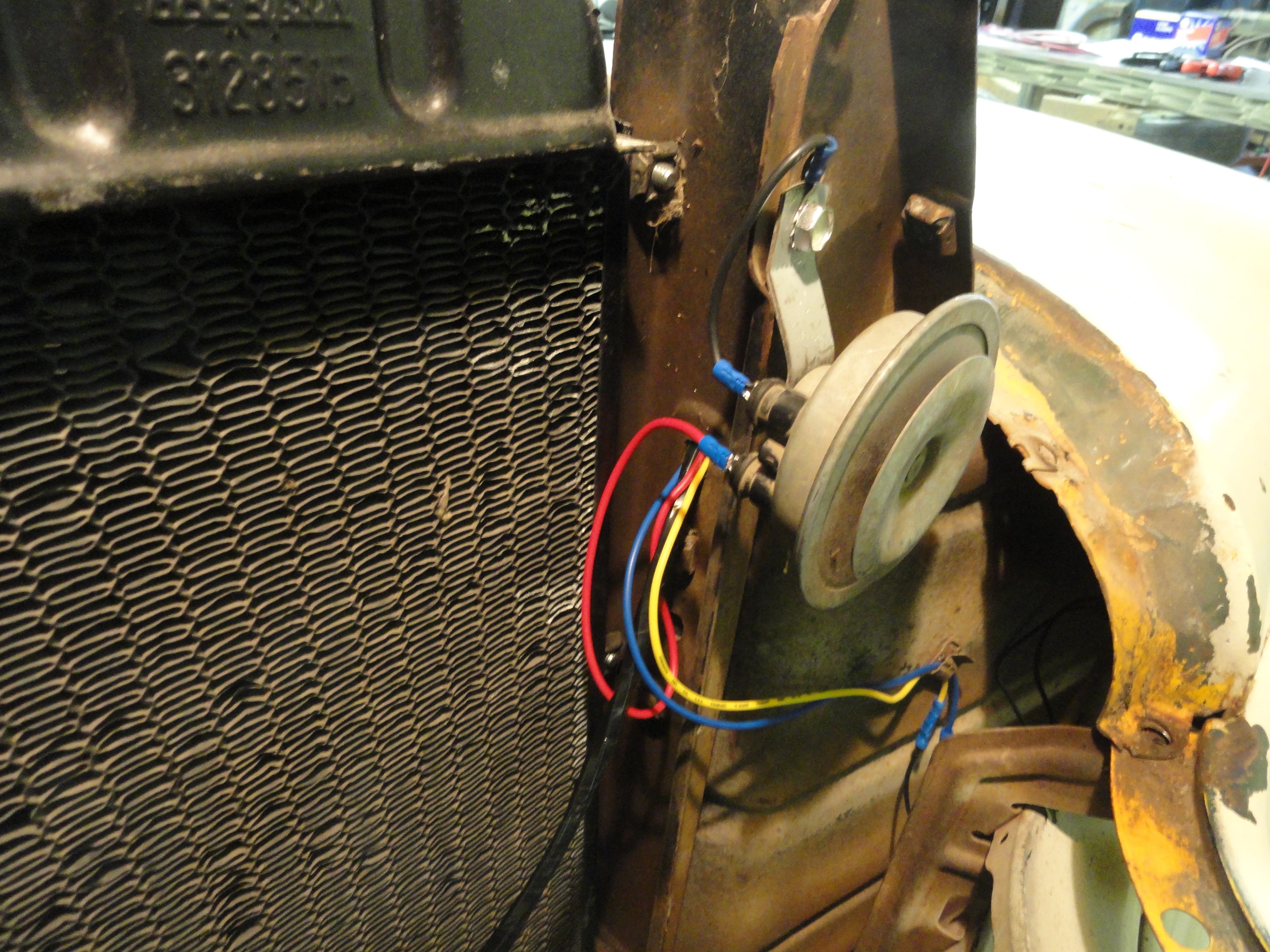
There are two wires coming out of each park lamp. The problem is, we do not know which one is the dominant one. You want the dominant one to be used for turn signals. You can either test the bulb using 12 volt power or take your chances with the understanding you may be switching the wires around later. Do both sides the same. Extend the lesser bulb wire to connect to the rearmost terminal on the inner fender. There is a nice little hole on the radiator support bracket just where it meets the inner fender that is perfect for threading through to the terminal block. I ran my horn and park lights through that on each side. The turn signal wire on the park light assembly goes through that same hole, then with a barrel splice you can spice to the proper turn signal wire when we install the main harness. So, to be clear, you have 3 wires on the drivers side going through that hole in the radiator support. Horn, Turn, Park. Park gets screwed down to the firewall end of the terminal block on the inner fender, the other two are left hanging for now. On the Passenger side, you have two wires going through that radiator support hole. Turn and Park. If you have two Horns, just jumper them together for power. The horns are expected to be mounted in that radiator support cavity since that is where the Harness puts them.
We are putting this here because we want to get rid of everything in the Harness Kit except for the Main Harness. This is one wire by itself labeled for installation as the Dome Light wire. It goes from the Headlight Switch (see diagram Step 8) through the A-Pillar right beside the switch up and over to the Dome Light. This is somewhat a revisit of Step 10 but now we are ready to install the new wire. Tape the old wire to the new one under the dash. The idea is to fish the new wire up through the A-Pillar using the old wire. Butt the two wires together and tape them sparingly but securely. Any wad of anything will not go through. Carefully feed the new wire up to the dome light. Once you have it threaded through the A-Pillar, attach the terminal end to the headlight switch. Using a barrel splice, connect the dome light end to the new wire. Secure the wires using the stock wire clips that are affixed to the lip of the inside roof.
With the goal being to get rid of all of the wires in the Harness Kit other than the Main Harness and extension wires, we need to connect the last single wire that is marked in the package. The wire needs to extend from the Battery Terminal on the end of the Headlight Switch to the bottom terminal of the Ignition Switch. This single wire is thicker than the others because it will power all of your switched items. Leave the included length in tact so it is long enough when factoring all of the gauge cluster stuff.
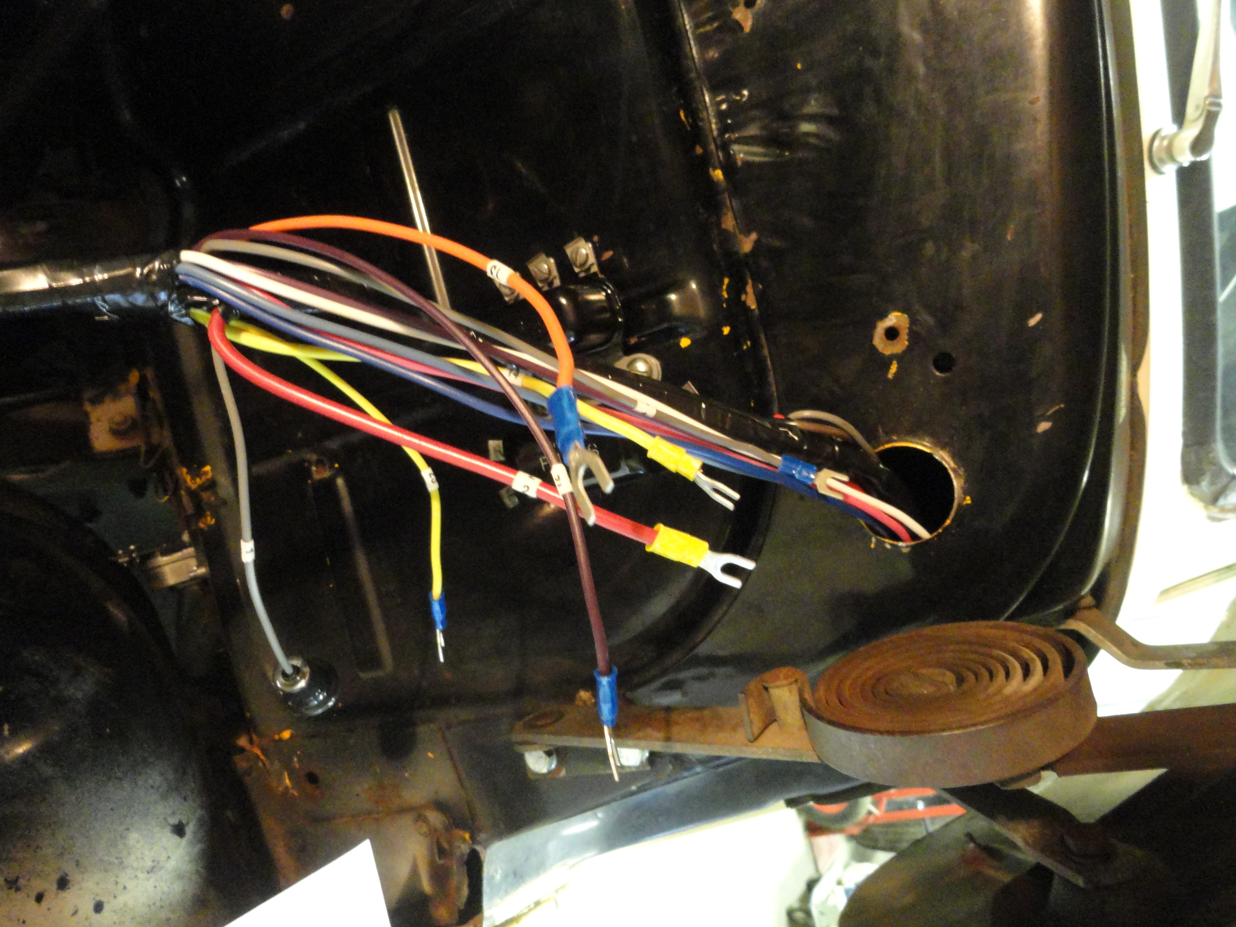
So we have put the main event off long enough! Let's spread this harness out across the fender. You will notice there are three branches, one has the gauge lights dangling from it, one has headlight terminals and the other goes down to connect with the Stop Light Switch, Dimmer Switch, Fuel Sender and Taillights. Spread it out so the gauge lights are near the Main Harness Grommet, the center branch that goes down is ready and the headlight ends are about where they would go.
Cut your Main Harness Firewall Grommet with an Exacto Knife from the center outwards so you can get it around the Harness. Feed the gauge lights, terminal wires, etc on that end through the Firewall. Feed things through until you see where the stop/tail fuse block and horn relay connect. The Harness Manufacturer did a wonderful job of spacing the wires here so they connect top and bottom. Go ahead and connect the Fuse Block and Horn Relay per the instruction sheet. This is just a matter of looking at the number of the wire, and corresponding it to the first page of the instruction. Very simple.
Next address the Headlight terminals, Park Light connections and Horn connections. Each wire is nicely marked and connects to its appropriate place. The harness loops across the front of the radiator over to the Passenger side headlight. Remember to observe the proper inner fender terminal connections as described earlier (step 16).
With the headlight, parklight and horn wiring out of the way and the gauge wiring stuffed through the firewall, it's time to address the branch that goes down and back to the fuel sender and tail lights. First, you will find terminal ends for connecting the Dimmer Switch and Brakelight Switch. You will also notice clips on the firewall made for the purpose of holding these wires in place. Use your wiring instruction to put these wires where they belong. Refer to the Dimmer Switch diagram in Step 7. The Stop Light Switch doesn't care which wire goes where, just that they are FOR that purpose.
Now we have a bundle that needs to find its way down the drivers side (inside) frame rail. Thread the rest of this portion of the harness through to the drivers side inside frame rail in such a way as to prevent problems with moving parts such as brake pedals, etc. There is a clip on the bottom of the firewall that helps with this. Once you have your path correct, the next thing we install is the Fuel Sending Unit Wire. Before we get there, use those Adel Clamps. Secure your wiring as you go. The sending unit wire will be numbered as such. It goes through the bottom of the cab near the gas tank. You will need to remove the seat back so you can fish it out from the floor. Once you have it through, connect it to the center of your fuel sending unit.
At this point, you will have wires with barrel connection splices on them. They will be numbered and ready for continuing to your tail light assemblies. Do the best you can to maintain color coding in adding length to these wires. If you have your 7 wire turn signal switch, one of the wires can just stop and go nowhere. In my case it was wire number 22. The turn signal switch will control the stop lamp circuit. Follow directly down the drivers frame rail for the drivers side tail light. Back in the day, you would be finished since they didn't have a passenger side tail light. I went across the rear frame rail crossmember with my wires to the passenger frame rail.
Once you get to the tail lights, there are grommets on the side of each frame rail or there should be. Install a new grommet and then thread the two wires through it to the tail lights. Again, you want the most dominant light, in this case the center bulb, to be your brake light. Open the tail light to determine the color of wire that corresponds to that one and connect accordingly on each side. That concludes the outside part of the Harness Install!
The Alternator connection has a provided plug to make everything very easy. There is the main terminal wire that goes to the Ammeter Positive and then the two smaller wires. One is jumpered direct to the main terminal on the Alternator, the other goes to the Ignition Switch. The one that goes to the Ignition switch is your idiot light function. More on that in this article: Adding a CIS. I mention this here so you know there is more fun to be had!
Now for the Fun Part! It is not as big a deal as it looks. Work from the floor of the cab. With the gauges sitting on the floor, you can more easily manipulate the wires. Be careful when connecting to ensure you do not route a wire on the wrong side of an obstruction. Be careful and deliberate and you will be fine. Install light bulbs in each socket per the parts list. Push the sockets into the gauge cluster, two for the left cluster, three for the right and one for the ignition switch housing. The third one on the speedometer cluster must be numbered to correspond with the high beam indicator. If the wires are too short to work from the floor, let them dangle wherever they want. Follow instructions on which wire goes to which terminal carefully.
The Fuel Gauge may need extra attention. If you are going to 12 volts, you will want to add a reducer OR order a new 12 volt version of the fuel gauge. The reducer listed in the parts listing will work great. Face the stripe of the Diode away from the gauge and using a round terminal on the non-stripe end and a barrel connector on the stripe end, cover the diode in heat shrink tubing to prevent a short and then install it on the power side of the fuel gauge. More information on how to do this is in another article called: Going Native!
As you can see, its infinitely easier to make these connections with the gauges and ignition switch out. The headlight switch is the exception since the terminals all face the clusters making them easy to get to. There is no need to say much more about how to wire the dash items other than just follow the wiring instructions on page one of the Harness Install Document. They did not include a cigarette lighter wire but that would go from the top terminal (as installed) of the ignition switch to the lighter center terminal for switched or to the back of the headlight switch for unswitched. Remember those two locations so when you add accessories, it is no problem for you.
Button everything up carefully. Once you are sure your terminal connections are made solid and your copper tubing is routed properly, reinstall the gauges using the 4 nuts per cluster you removed when taking them out. Install the Ignition Switch using the two 1/4" bolts and nuts. Check over everything physically to make sure everything is tight, well routed, and clean. Once the gauges are installed, it is VERY hard to get to connections, so be sure of your work as best you can.
If you were careful and meticulous, your installation will be absolutely bulletproof. Apply battery power and watch carefully for any smoke or strange noises. Then here is a list of things to look for.
This is by far the easiest Harness to install I have run across. If you follow each numbered wire corresponding to the instructions, you simply can't lose. If you do run into issues, you can usually think your way through them. This is because of the intuitive nature of the harness build. This cannot be said for all harnesses. I was impressed with the ease of the install, the Kit contents were above average, and when its all said and done, your truck is back on the road again with none of the worry about all of the old frayed wiring. Of course, small things were criticized, but in my opinion, if you didn't have to run to your local auto parts store for something small more than twice, you have a winner! If you have questions or comments about any of the information contained in this article, email deve@speedprint.com or go to Forums.Devestechnet.com and start a new thread. Good luck!