

Deve's Technical Network
1947-1955 1st Chevy Trucks
216/235/261 Engine Solutions & More
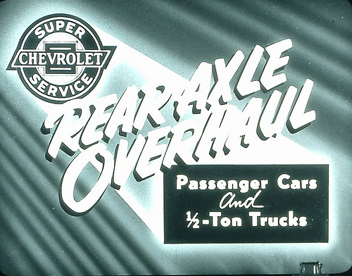
First off, nobody tells it better than GM, so here is the Film version of Rear Axle Overhaul produced in 1952 and covers the Passenger Car and Pickup versions of the Torque Tube Assembly. Special Thanks to Brad Allen for restoring these filmstrips and making them available to us. This particular slide set will really help you understand how the parts go together and what the thinking was behind this magnificent invention. We will then explain in detail how to upgrade your stock 4:11 gear set to a much more efficient 3:55.

Ok, so this is NOT going to be Easy, but what sets this procedure apart from ALL the rest is, we are going to do this without touching the connection at the Transmission! Everything will be done in the back! The closest we get to the U-Joint/Tranny connection is the 3 set screws just forward of the Pumpkin! Doing it on the Truck, without disconnecting the Transmission will save us LOTS of man hours while still doing a very competent job.
First off this procedure does require some mechanical experience. Please read all of the document first and then decide if this is for you. Also, there are other references that are worthy of a look before taking this on. If I left something out, let me know.
Your vehicle's Shop Manual Section 4 - While this is very informative and recommended reading, none of us have all of the specialty tools they recommend and most of them are unnecessary.
Be sure to watch the above Slideshow! It is the very same material as used to create the Booklet Rear Axle Overhaul and has a lot of really good pictures and explanations that will help you.
Patrick's Installation Instruction (very good if you can get it) - Patrick's instruction is almost like this one in that he does not remove the entire torque tube system from the truck but his article talks about the front bushings and removal of the connection at the transmission. It's a good read and very instructional. As far as I know, it is not available on the Internet.
Chris Sweet's Installation Instruction - This is very good especially if you are taking the entire truck apart for restoration. Chris has a good way of explaining things.
I am always looking for bargains, but I also want unparalleled quality when it comes to something that is this critical to the Driveline. I have found all the usual vendors to have good quality Gear Sets. For you 47-55 drivers, the new gear set you want has a 3.55:1 Gear Ratio. I ordered my new Gear Set from a company out of Tucson, Arizona called Mother Truckers. Joe has a large quantity of these gear sets and sells them about $100 cheaper than the closest competitor. I found the gear set was brand new, in new packaging, and secured very well for shipping. I would not hesitate to purchase from him again. I also found the quality to be very good. You can get ahold of them via email at mothertruckeraz@aol.com.
Besides the actual Gear Set, there will be select Bearings, Seals, Gaskets, etc. that you may need. If you have a local BRC Bearing, or Murdoch Supply, or any company that specializes in Bearings and Seals, you can get them cheaper by eliminating the middle man. All you need is the part number which is supplied here. My estimate on total cost is about $600 for most installations TOTAL including the Gear Set. If there is nothing wrong with your Bearings and Seals, maybe much less.
These part numbers can be easily substituted and a good Bearing Distributor will have no problems offering you suitable parts. [1940-1954]
As far as shims and what is needed, here is EXACTLY what you need. Shim's Outer Diameter (OD) is 2.833. Shim Inner Diameter (ID) is 2.370. Shim Width (ID to OD) is .230 which is close to 1/4 inch (or 6mm). If you end up with a bunch of metric system nuances, OD is 72mm, ID is 60mm and 6mm thick. Keep it American so the Caliper info is the most correct. You need at least .003 (x2), .005(x2), .010 (x2), .015 (x2) and .020 (x1) to make sure you have every combination of possibilities.
NOTE: This is the list that includes everything necessary within the "Installation Kit" that has to do with the Gear Swap. As of this article, Oakie Bushings are not available at all. Oakie Bushings are a replacement for the still available Front Bushings for the Torque Tube, but that is not within the scope of this article since we are not removing the front connection at the transmission.What sets you apart from the mechanic down the street who charges $80 an hour is, you have to drive this truck when you are finished. So, think HARD about your skill set. The Mechanic down the street is experienced and knows what to look for. If you decide to do it yourself, be sure to err on the safe side. For example, if there are any pits or bumps on the Axles, it may be necessary to install a Speedi-Sleeve (for seal contact area only). Take lots of pictures and really have your thinking Cap on when doing this!
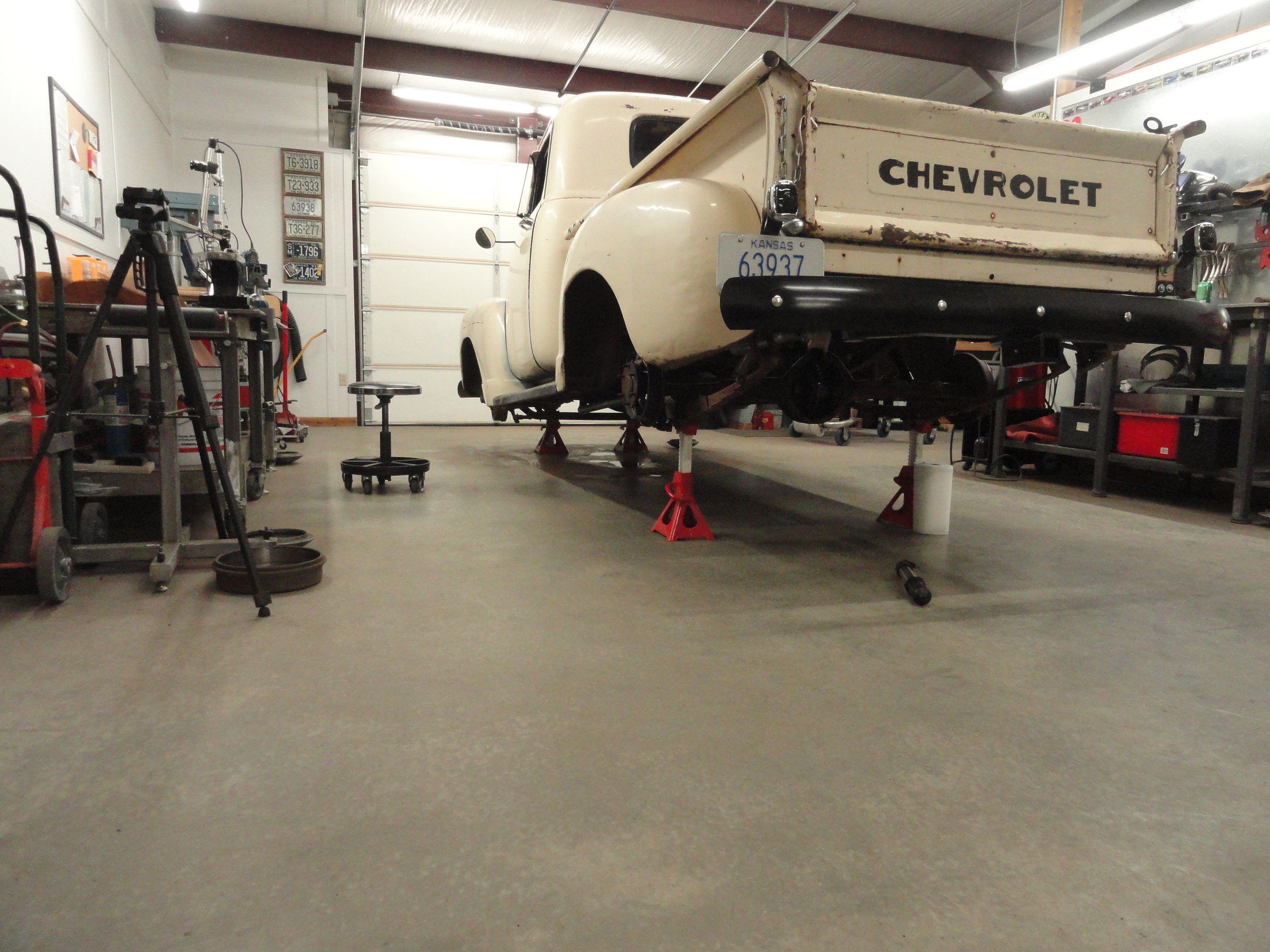
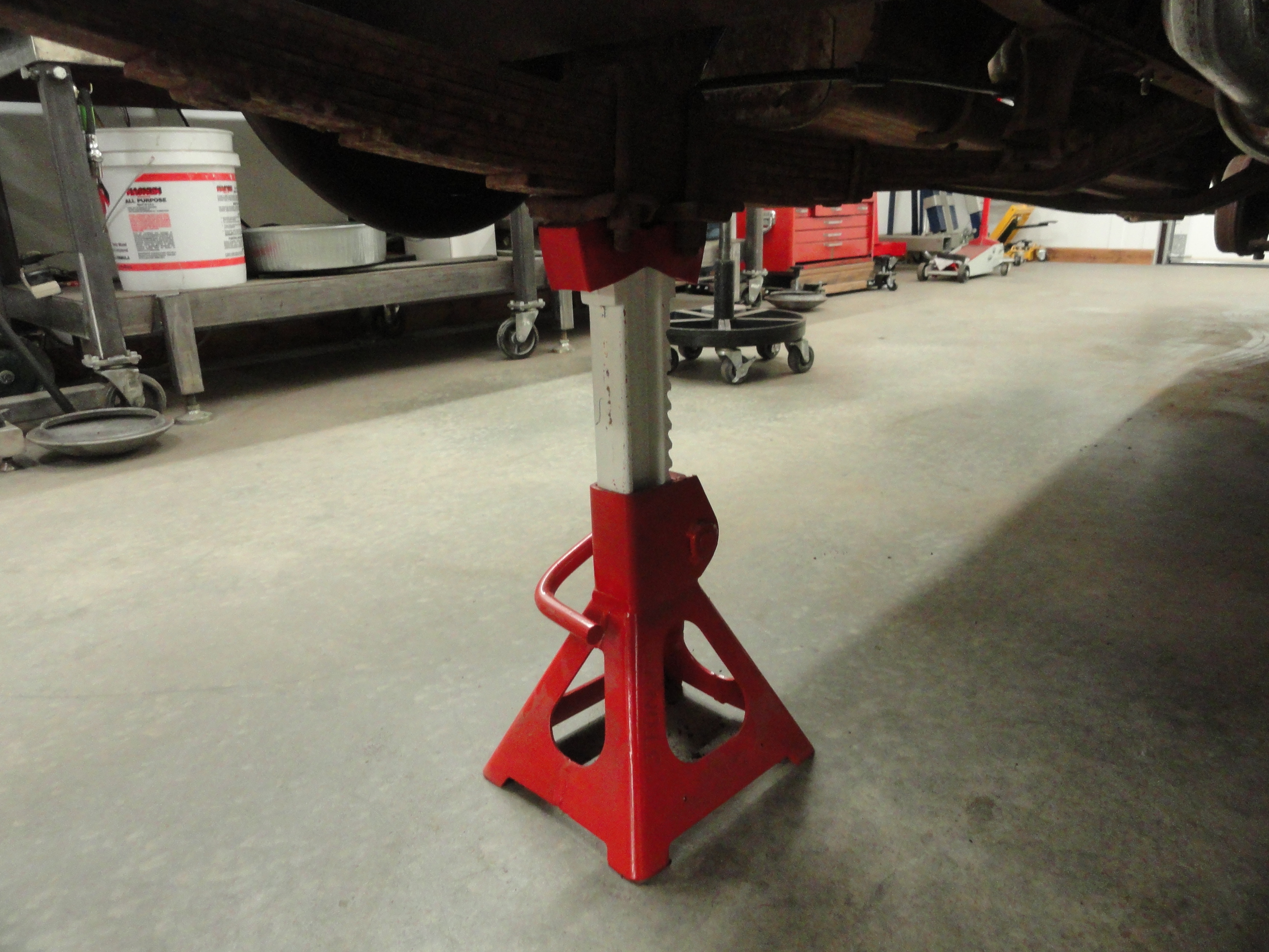
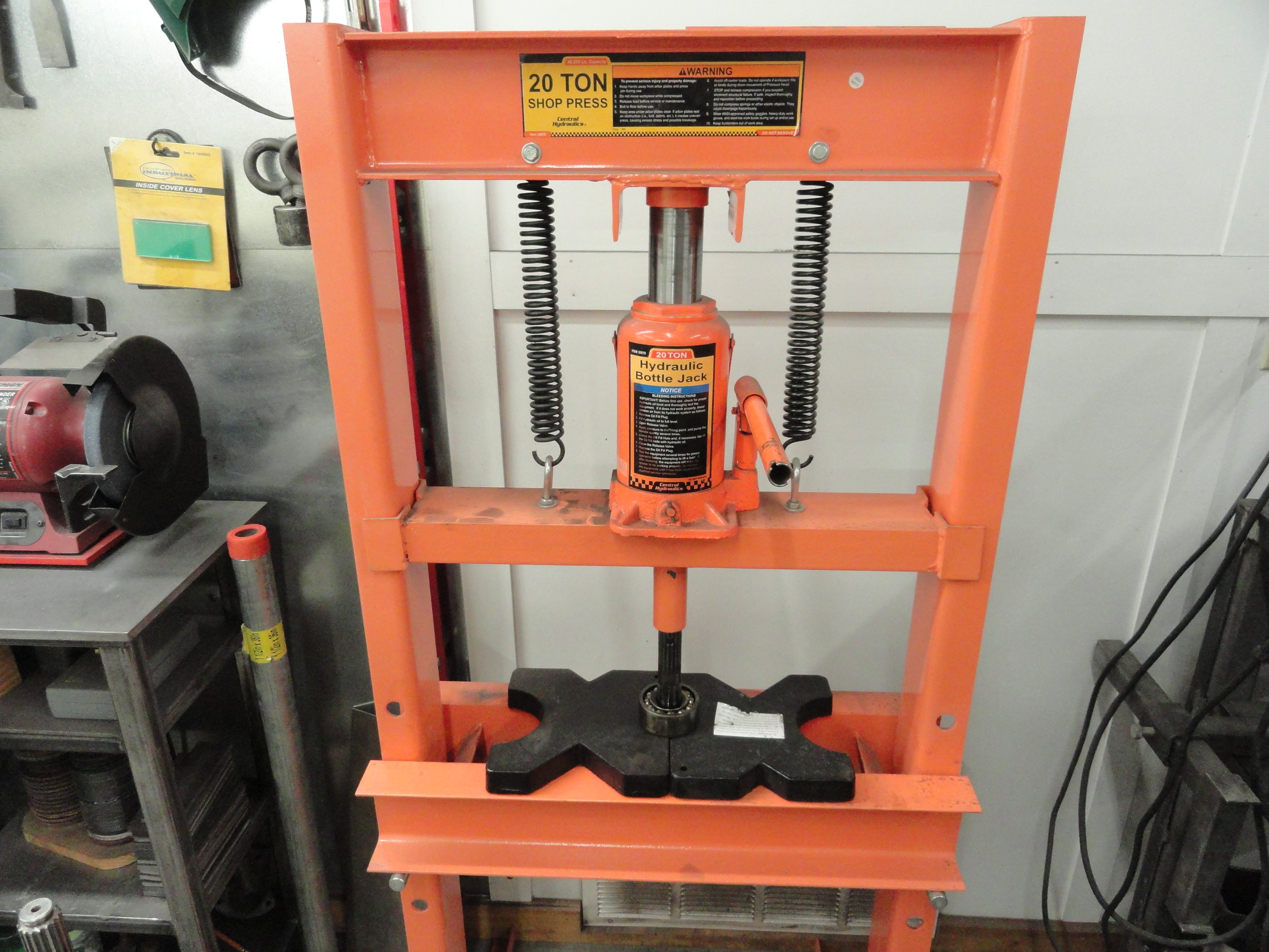
Jack the truck up high enough to give yourself easy access to everything. If you have any spare tire carrier, or anything that is in the way of a straight out extraction of the very long driveshaft, you will want to remove the obstacles. Use good quality Jack Stands and put them under the leaf springs in the center anchored solidly for safety.

Remove the bottom three bolts on the Differential Cover to drain the Gear Lube. Once it stops dripping, remove the other 7 bolts and lock washers. Clean them up and place them to the side for later re-installation. Clean up the Cover, Drain Plug, Brake Line Clip, and the ten 3/8" (24) by 13/16" and replace the 3/8" lockwashers.
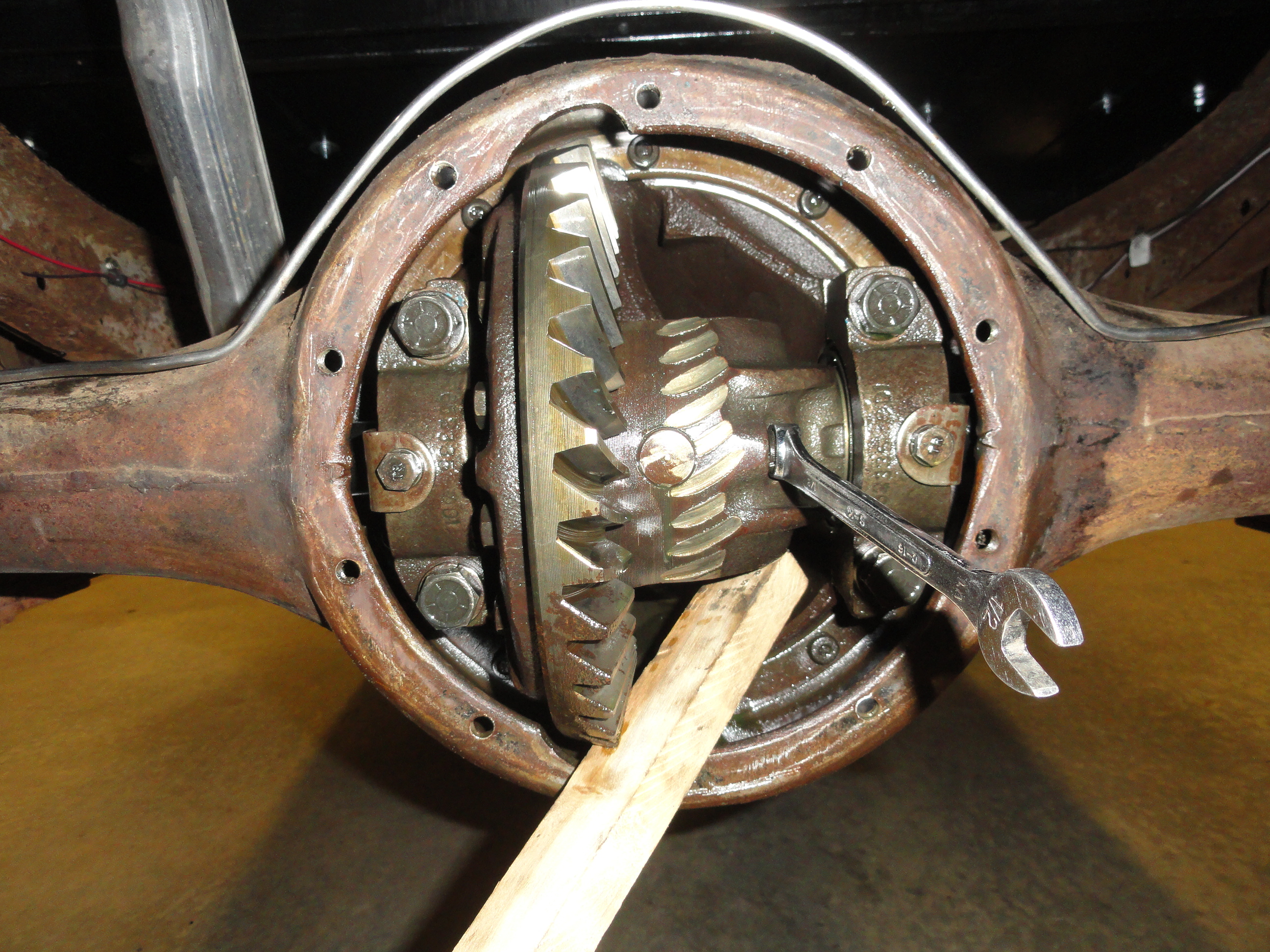
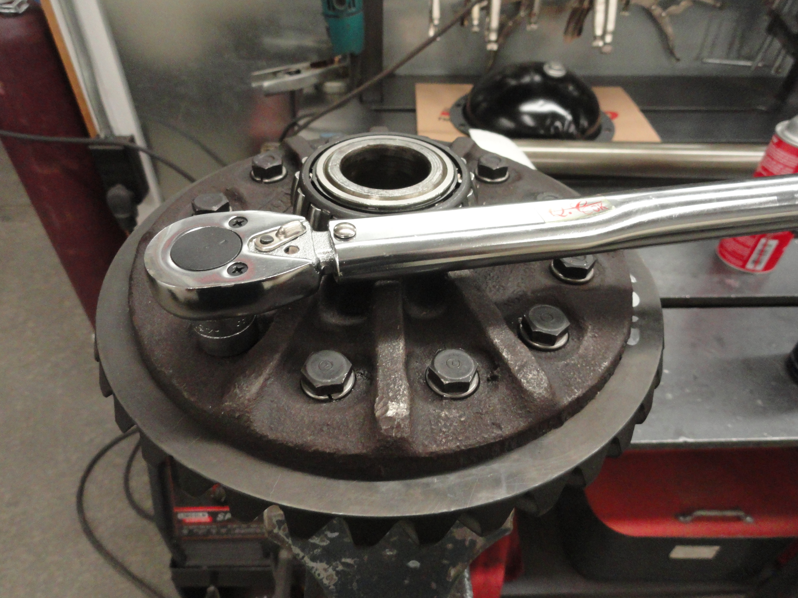
Since I get confused as to which direction to flip the brake spanner, I made THIS. With the drums removed so we can get to the Axles, we are ready to pull the Axles out for further inspection. Start by removing the lock bolt from the pin that holds the large block in place as shown. Use a 1/2" wrench and remove the special bolt that acts as a pin. Inspect the pin to ensure it's serviceable and set aside. Remove the large pin that holds the center block in place. It should just fall out if you rotate the assembly properly. Set the pin aside. At this point you can pull out the steel block that separates the axles. It should just fall out as well.

Push the Axles inward and you may hear a 'tink' which is the sound of the C-Clips falling out of the axles inside the differential. Push in both axles and then with a telescoping magnet tool, probe around for these clips as shown. Pull out the Axles carefully being sure to keep the shafts centered so as not to disturb the very delicate seal at the backing plate. We haven't inspected any of this yet and there is some inspection to do! In the case of this particular truck, the Axle Bearings and Seals were in very good shape so I opted to not replace them. It is VERY possible that you will not be so lucky. So, let's discuss what to do.
Axle Inspection: First lets take a look at the Axle shafts. Clean up the smooth area where the bearings and seals ride on the Axle. In good lighting, check for pits, or ridges that could cause seal leakage or bearing damage. If you feel there are ridges and/or pits that could cause seals to not seal properly, you can get a Stainless Steel Speedi-Sleeve that goes over that area and makes everything smooth again. If there is damage in the Bearing area, you should replace the Axle. These sleeves are not cheap (about $60 each) and they are also not easy to install. The trick is to put the axles in the Freezer and get them very cold, then use a long pipe that just barely slips over that Axle area to carefully pound the sleeve into place. The option I choose, since my wife does not take kindly to my using her precious freezer for Axles is to take it to a good mechanic that does this routinely and just pay to have them installed.
Axle Housing Inspection: Look around the hole for wetness that could be caused by a leaky seal. If the area looks like gear lube has been getting past the seal, replace the seal. To get the old seal out, since it is not reuseable, I just pull it out with pliers or jamb a screwdriver into it and bend it out being careful to not disturb the bearings. With the seal out (or not), let's look at the bearings. Does the bearing race look serviceable? How about each bearing? Does everything spin freely? If there is any doubt, remove the old bearing with a 3-Jaw Slide Hammer. Clean the area where the bearings and seals go thoroughly, then spray some Lithium Grease in the area to make the new bearings and seals go in smoother. Clean the Axles and ensure the drain hole is clear of dirt and grime. Check the threads on the Studs for serviceability and replace them as needed. Brake Cleaner Spray is a good choice for cleaning these parts.
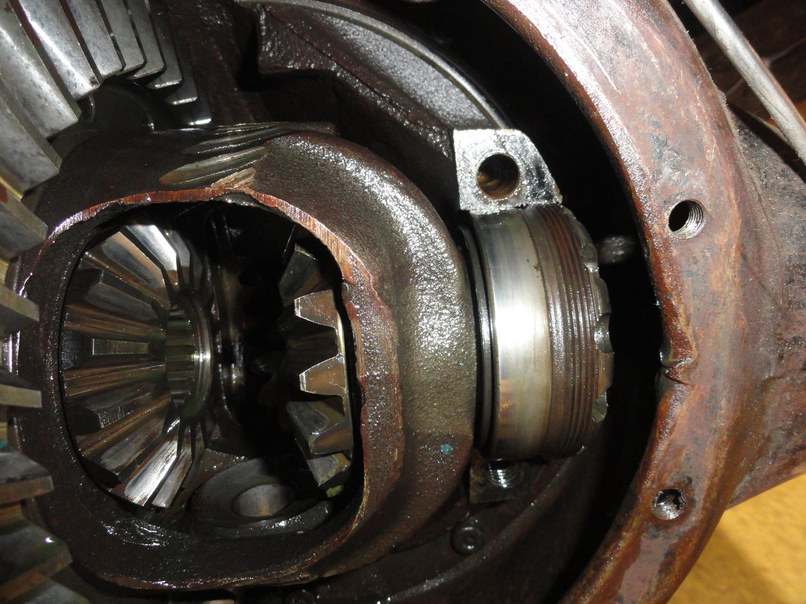
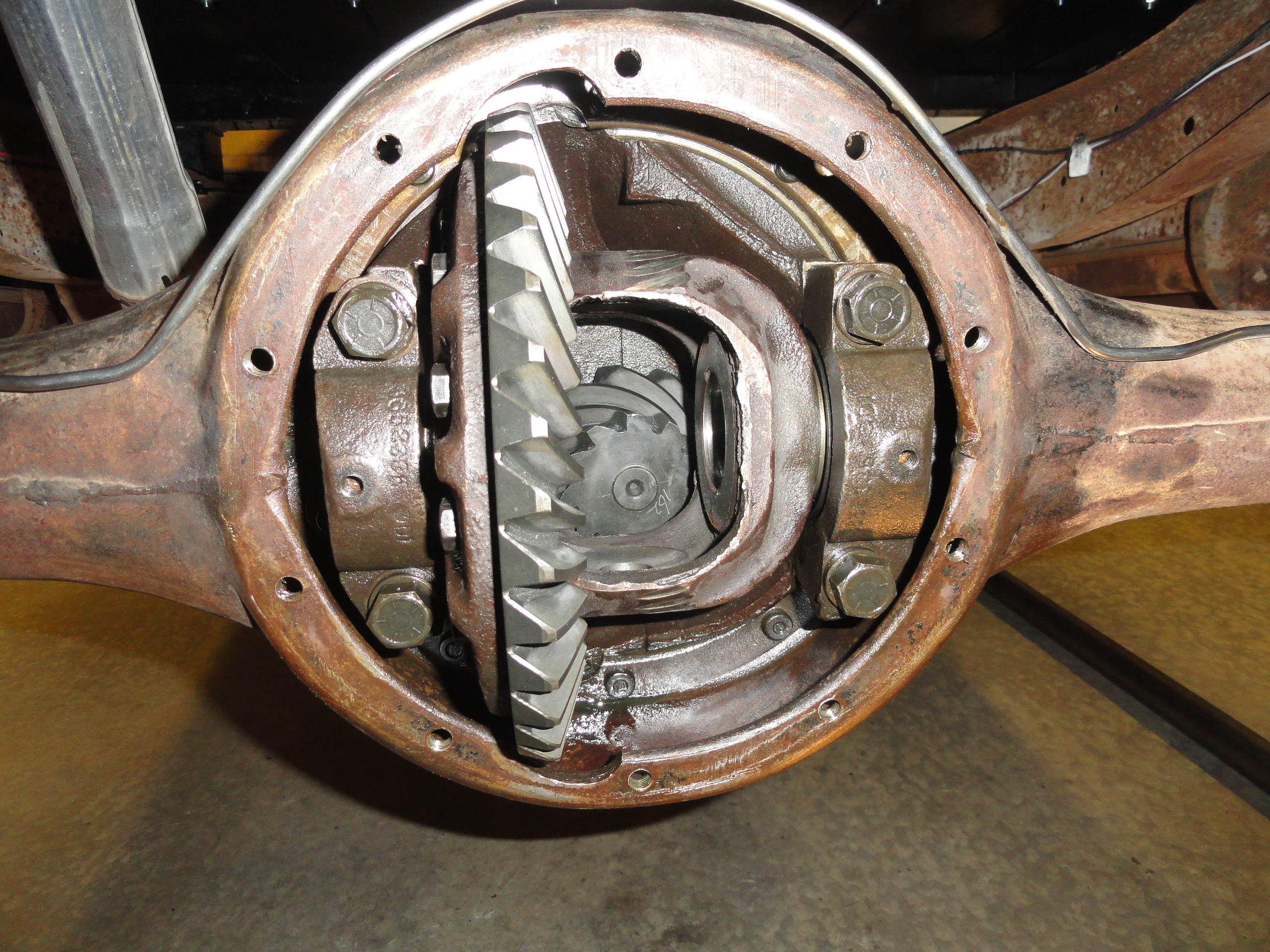
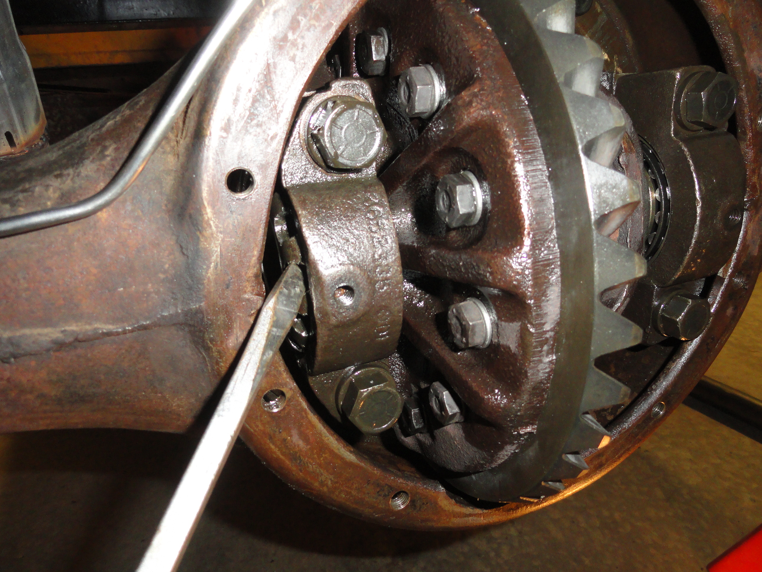
The bearing retainers come out first. These little clips are held in with a 1/2" Wrench and located on each side. Always, with the exception of above, keep all hardware in their respective locations and do not interchange left and right hand parts. With the two retainers out and identified, remove the four large bolts with a 13/16" socket. For me this was harder than I expected. My Impact Driver wasn't able to do it, my short breakover bar didn't cut it, so I broke out the big breakover and finally got them out. Remember, with those bolts clear out, that entire assembly will just fall out! Be ready for it! I left one of the bottom bolts slightly in until I got into position to pull it out. With the Ring Gear Assembly removed, clean out the entire Pumpkin with solvent to ensure everything is very clean.
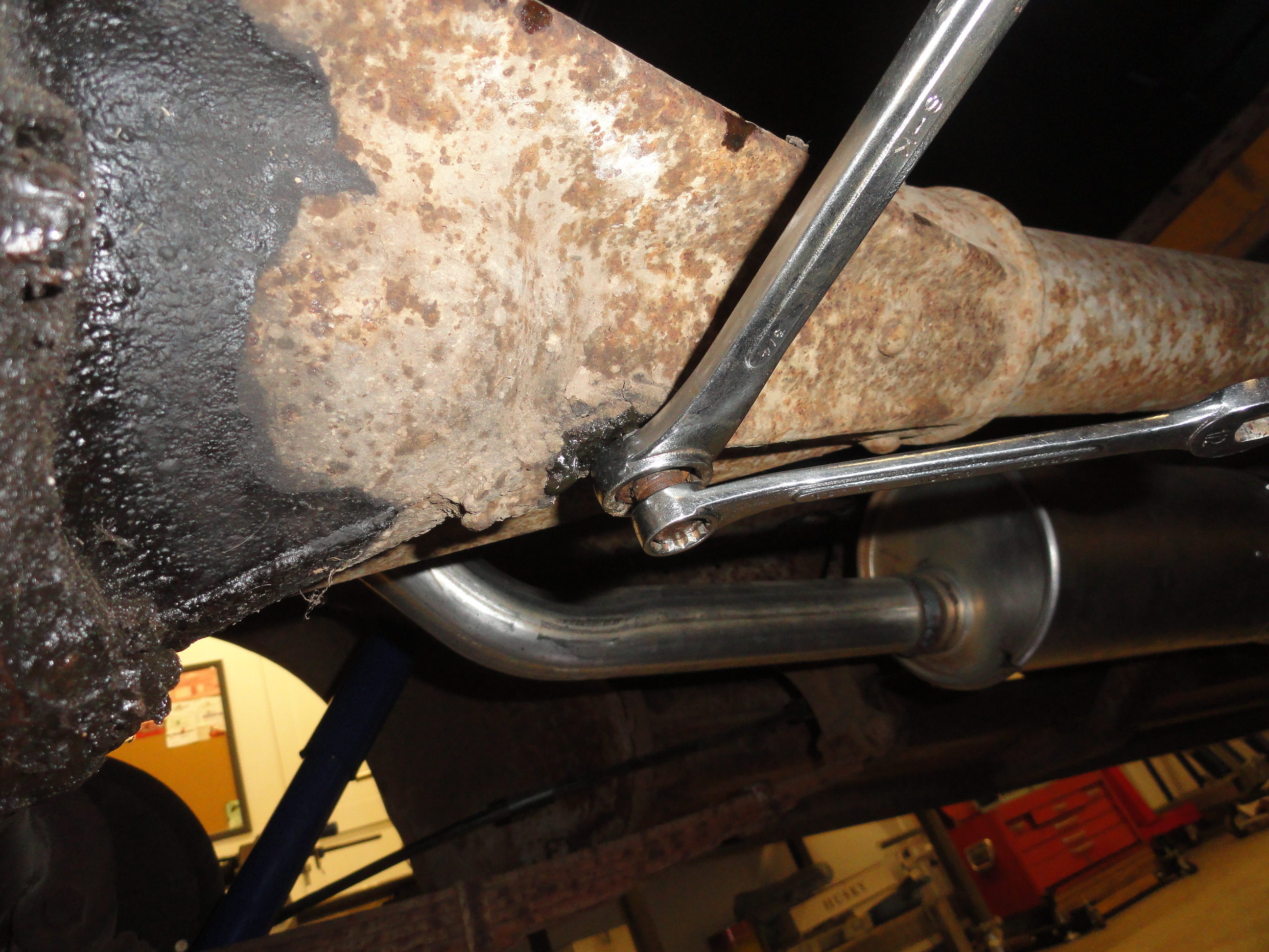
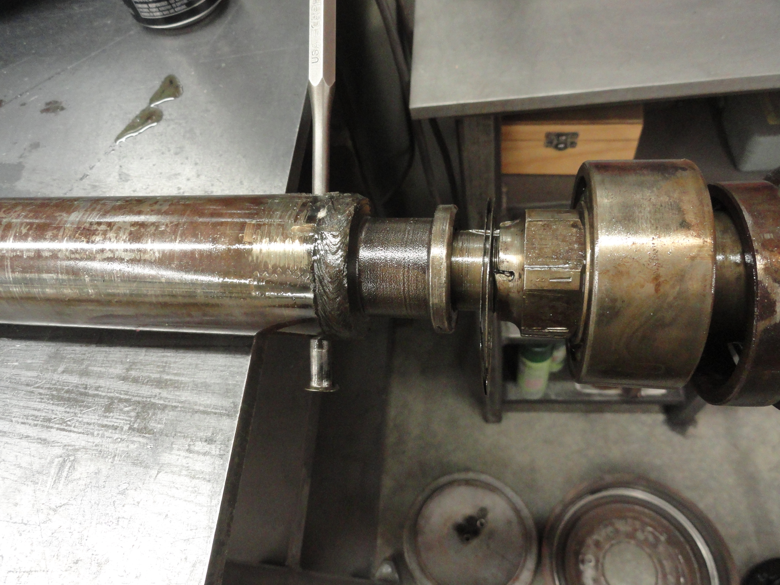
The glory of this procedure is not having to remove anything at the transmission end. But to do this, we need to pry the pressed in Pinion Gear shaft along with the driveshaft out at the same time. The splined drive shaft will just nicely back out of its splines and everything will come out in once piece. We start by removing the three Set Screws surrounding the torque tube just forward of the differential assembly. These three bolts on the outside of the casing have 1/2" wrench head and a 3/4" lock nut. Loosen the lock nut first, then remove the bolt with the lock nut on it completely. Clean them up and have them ready to reinstall later.
With the set screws removed, we can get down to business. With a 20 inch Heel Bar as shown, put the lever end under the top of the pinion gear and push up to pry the Pinion Gear Assembly out. This can be relatively easy to very hard. In my case, it came out with just a little prying, but I have heard of having to put a hydraulic jack on the end of the prybar. Whatever you do, be safe about it. Once it comes out about an inch or so, it will be easy to just pull the very long assembly clear out. Take it slow and understand that you are prying on only one side so pry a little, turn it 180 degrees, pry a little more, etc. You CAN do this, it is just stubborn is all.

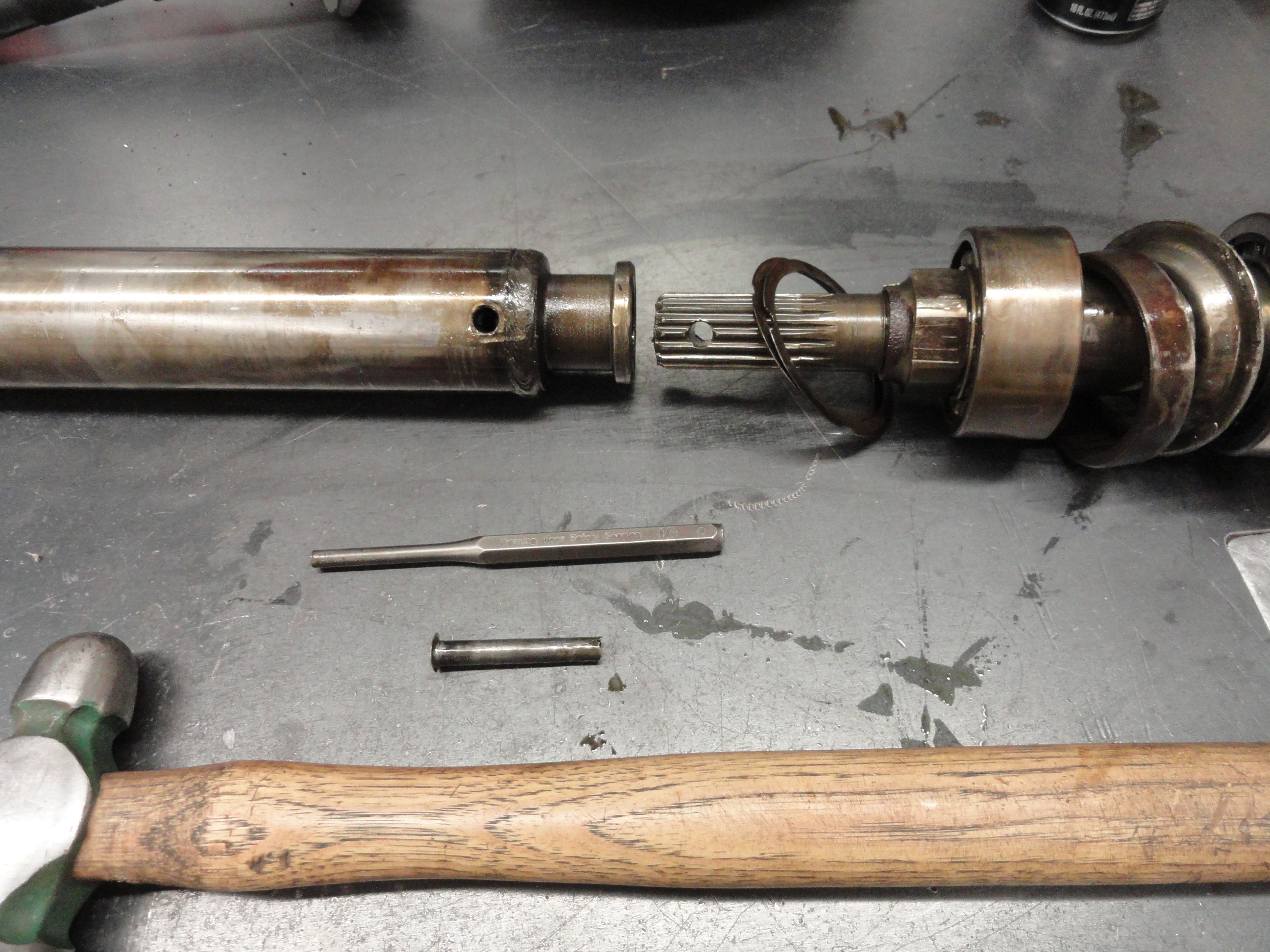
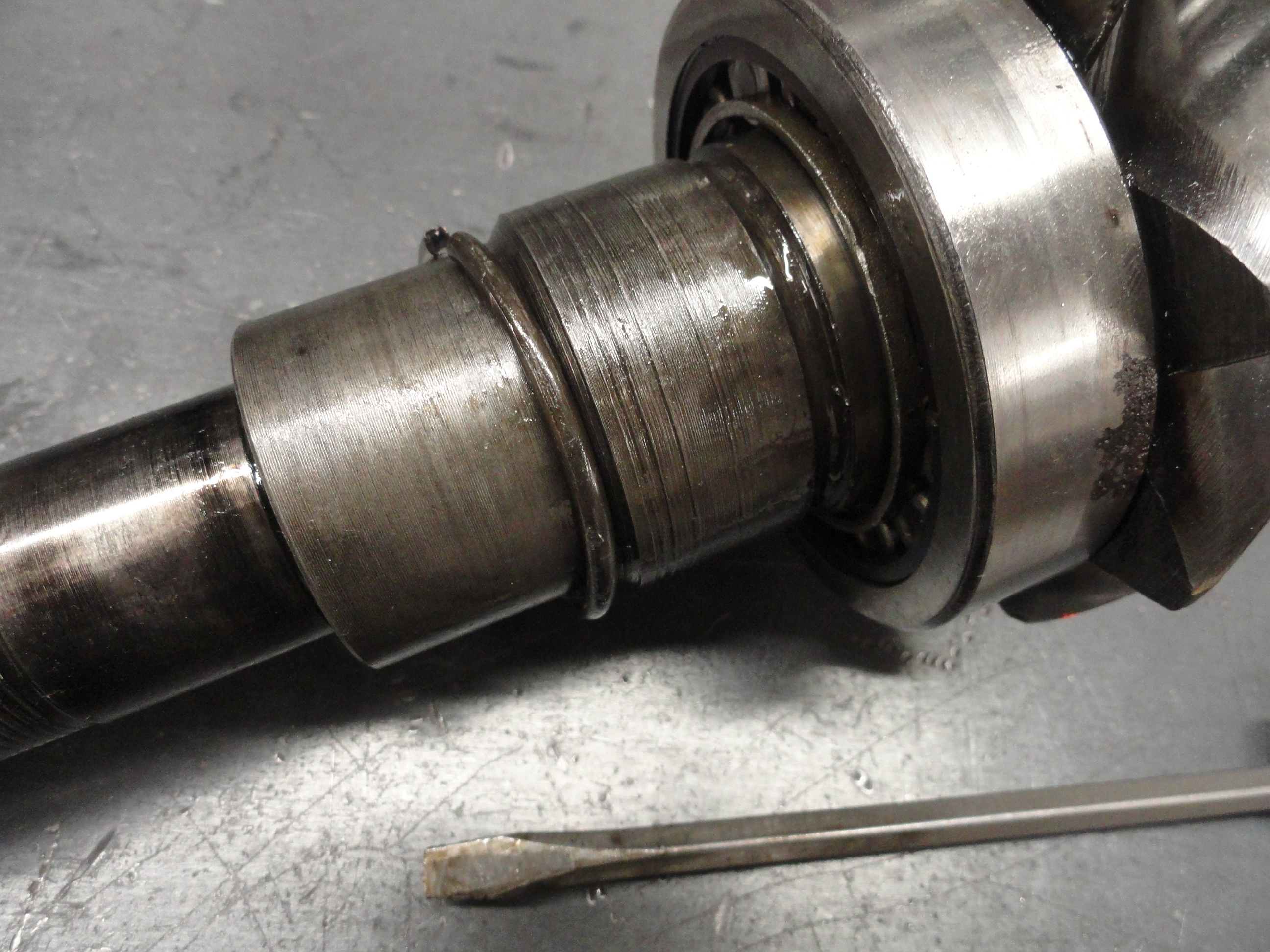
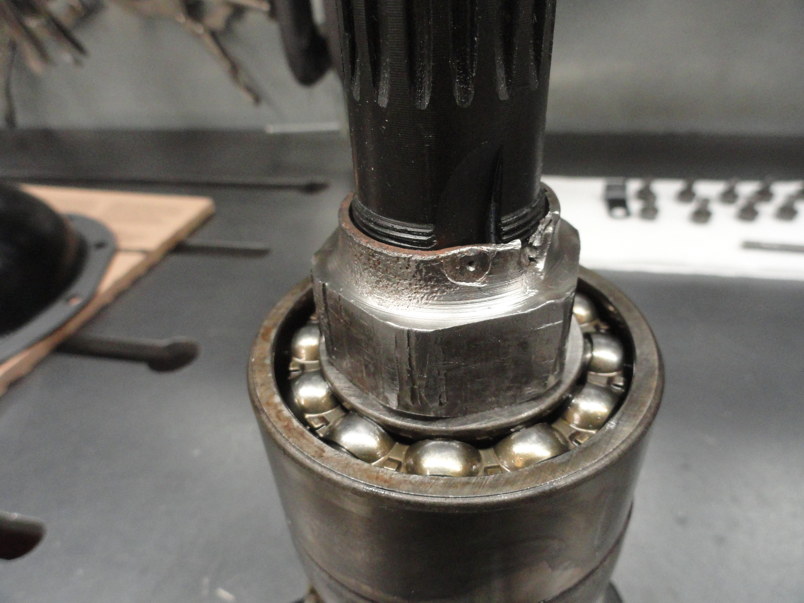
Slide the Assembly clear out and place on a good work bench. Now is when the fun begins! First order of business is to separate the drive shaft from the pinion gear shaft. You will notice at the weld on the Pinion end of the Driveshaft (about 1/4" in to the drive shaft) is a lock pin. Both ends are peened so the pin does not come out. This pin is not salvageable and will have to be replaced. To make it easier, grind off one side of the peened area, then drill a 1/4 Inch hole on each side about 3/8" deep or so just to relieve the pressure, then with a flat punch, pound out the pin. To make a new pin, get some 5/16" rod, cut it a little longer than needed so you can peen the ends. With the pin removed, the splined pinion shaft assembly will pull right out. (Do NOT reinstall the pin yet! We need to do some adjustments to just the Pinion Shaft!)
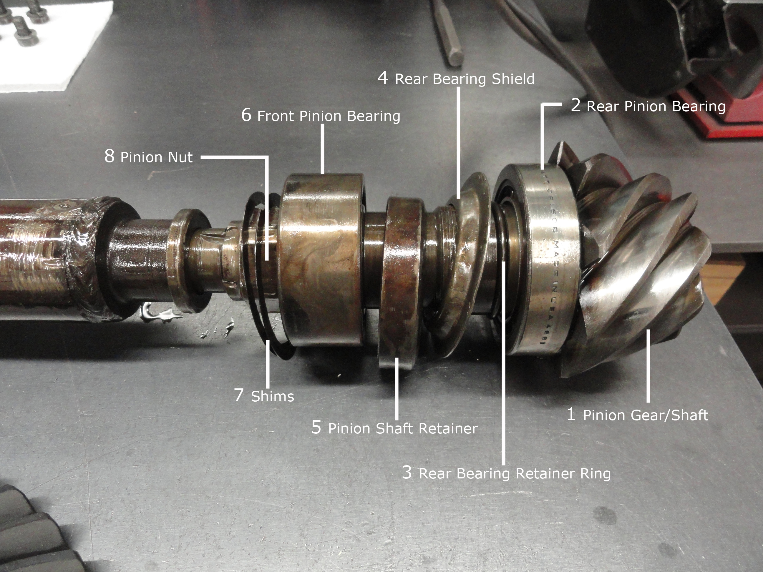
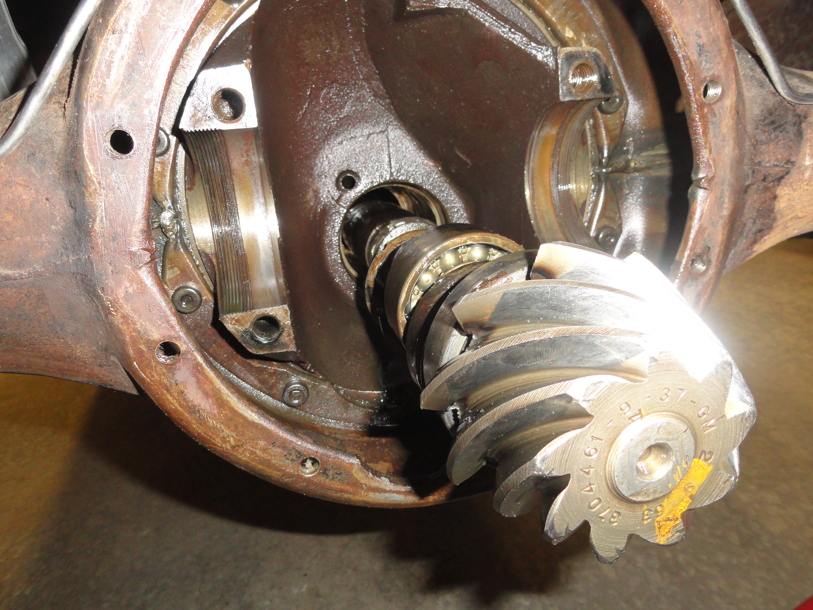
This is where we need to understand the placement and use of each of the parts that are attached to the pinion shaft. The diagram right numbers the parts and we will explain each one in detail. (2) is the rear Pinion Bearing. It rides almost up against the Pinion gear. This thinner bearing is held in place with (3) the metal retaining ring. Check this bearing for serviceability. Replace if needed. The retaining ring cover (4) is next. This is more or less an oil retention shield. Next (5) is the Pinion Retainer Ring. This seems like a part that doesn't belong where it is. Turns out this is the sleeve that the 3 lock screws lock down to and the hardest part of all of this. This sleeve has to be pressed up against the Main Pinion Bearing in order to go back into the shaft. We will address that problem later. Next is (6) the Main Pinion Bearing which is the thicker bearing. This one is pressed onto the shaft. Inspect that bearing carefully to ensure there is no side play and the bearing works freely. This one needs to be pressed out with a shop press or equivalent. Take great care to save this bearing if it is serviceable because it is an expensive item. The next items (7) is the Shim Pack. Mine had two shims in the back of the thicker bearing. I have been instructed by my specialist to put a .010 shim with the two that are present to start with.
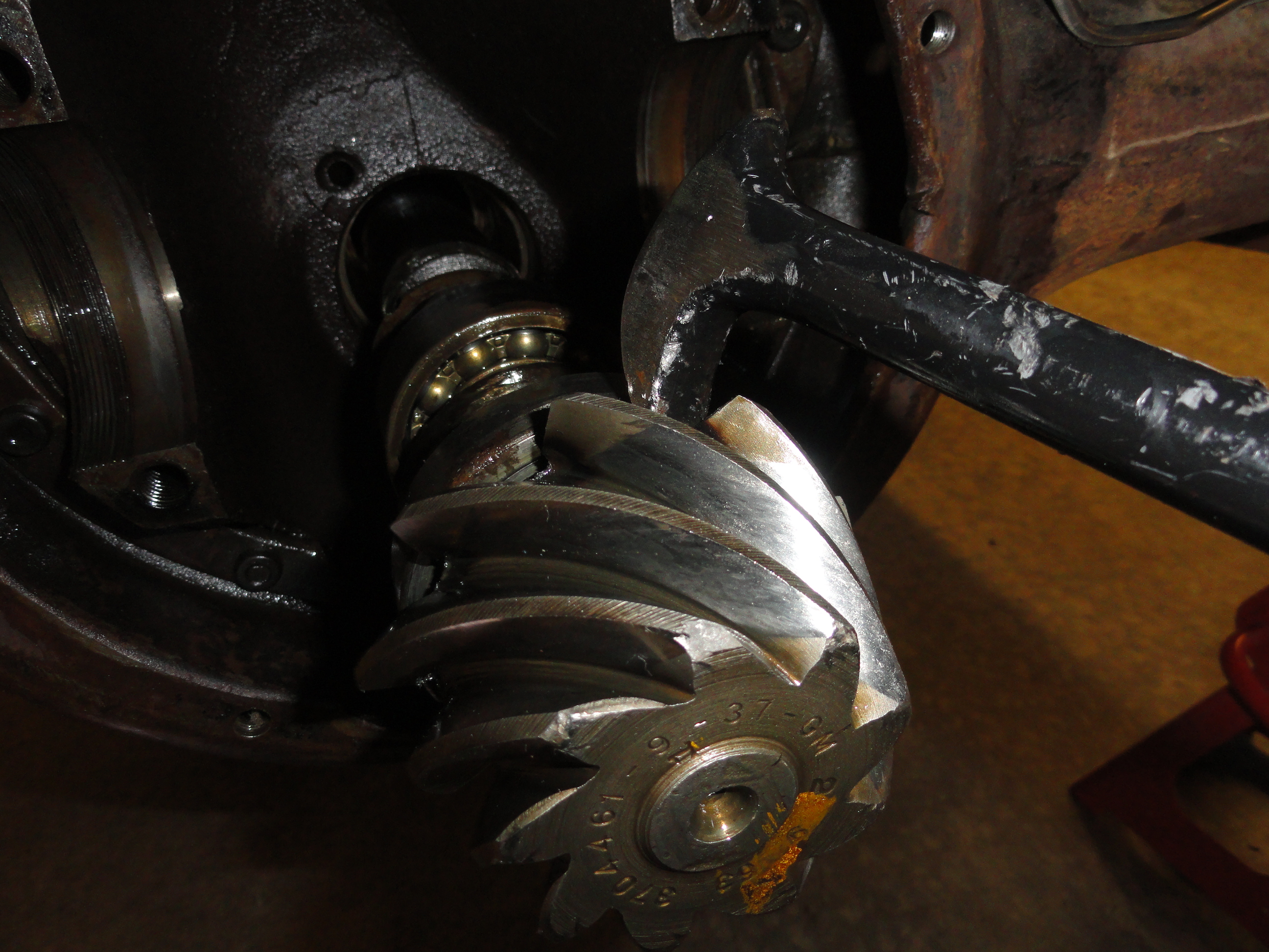
THE hard part in this part of the procedure is getting the Pinion Nut (8) off. It is not only torqued to 240 foot pounds, but it also has been smashed near the bottom where that half-moon cutout in the threads on the shaft is located. They did not want this thing moving! First find yourself a 5/16" by about 3 inch hardened bolt to stick into the pin location so the splines will not turn in the vise. The vise does minimal or no damage to the splines if they are secured properly when clamping, however, if you plan on re-using this 4:11 Gear Set, a very good way to protect the splines is to find yourself a used U-Joint Yoke and put the splined end in the Yoke before putting it in the Vise.
I will never be using or selling a 4:11 pinion gear so I am not overly concerned for the shaft. The nut is another issue. Look over the nut carefully. You will need to pry the 'damaged' punched down part out so it is not working against you. I used a screwdriver that was just the right size for the slot to start bending it back, then slid a small tapered punch under it to finish pulling it up. In my case, this nut had two indentions, so I had a little more work to do. I then used a 36" by 1-1/2" Galv Cheater Pipe on the end of my largest Crescent Wrench. To be honest, I tried it without the Cheater banging on the Crescent with a large Hammer and got absolutely nowhere. I feel the Cheater Bar was the thing that solved the problem. With the Nut out, clean and debur it thoroughly.
Next we need to remove the (6) Front Pinion Bearing. Do not get mixed up with terminology, the front means the front of the driveshaft assembly, so we are first working on the thick (front) Bearing. This has to be pressed out. There is no better tool for this than the Shop Press. Especially if you are interested in preserving the Bearing. In this case there is nothing wrong with the Bearing, so the plan is to reuse it. With the Shop Press set up properly having the two pressure plates situated so as to balance the pressure, we just push it out. A good idea is to mark which side of the bearing faces where. You want the bearing to be oriented the way it was on the other shaft. If there is any doubt about the proper orientation, refer to film strip number 37 above.
Next the Pinion Retainer (5) just comes right off. Be sure to mark which side goes towards the front pinion bearing. This is a specially tapered item so it matters which side goes where.
Next to be removed from the old Pinion Shaft is the rear bearing shield (4). This orientation matters too. Be sure to get it so it shields the bearing. Pay careful attention to the pictures and you should be fine. Next comes the Retainer Ring (3) for the Rear Bearing. (This is the Bearing closest to the Pinion Gear). I just used a few small screwdrivers to pry the ring out and down where it can be easily slipped off. With the Retainer Ring out, the Rear Pinion Bearing (2) slips right out. Check for serviceability. Set all parts aside after cleaning.
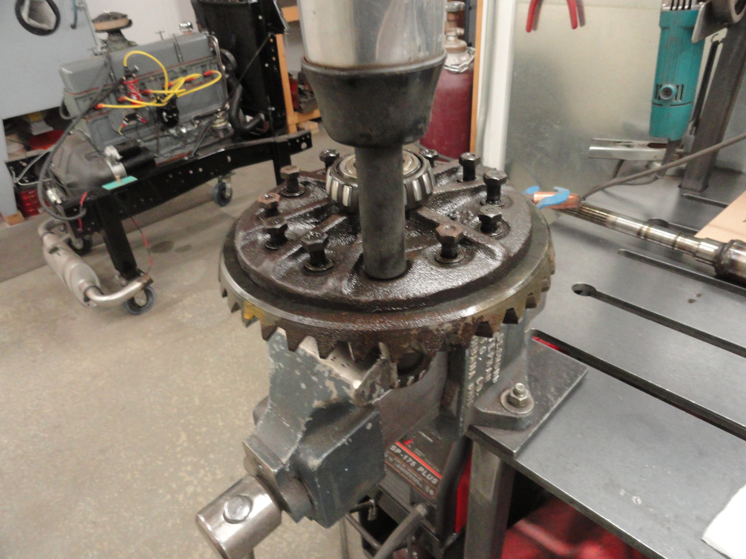
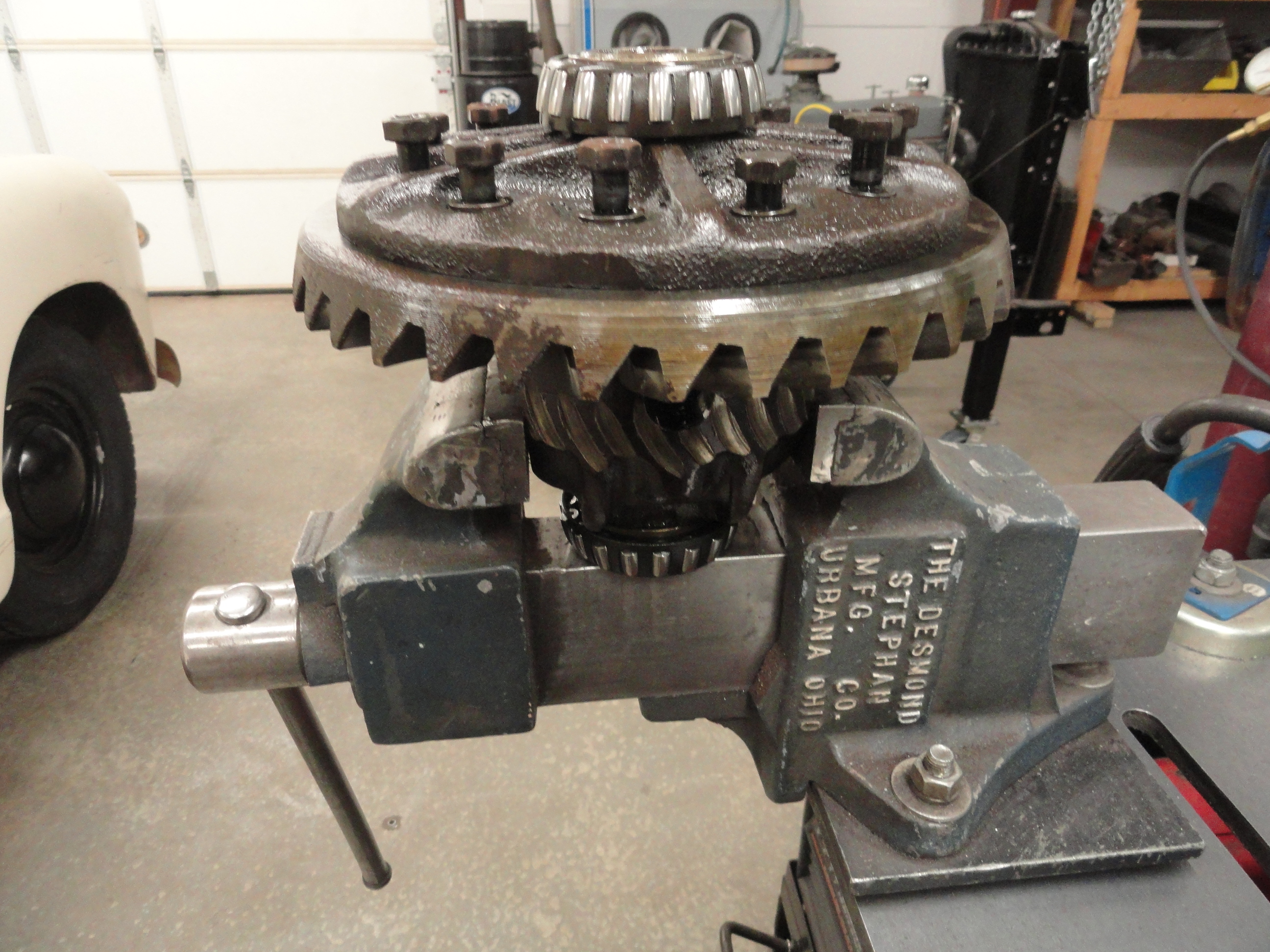
This is where it is nice to have an air or electric impact wrench. There are 12 3/8" bolts that need to be removed to get the old Ring Gear off. With the bolts removed, use a brass hammer or in my case I used a rubber mallet to knock off the old ring gear. With the old one off, let's use a flat file to clean up any burrs that could cause the new gear to install poorly. Run the file around the entire path the new gear takes to get completely down flat. Once you do this, be sure to clean the assembly very well. I use lacquer thinner for this so everything is perfectly clean. Use new 3/8" lockwashers and clean the bolts thoroughly.

At this point, we need to make 3 alignment bolts so that we do not run into issues trying to get the bolts aligned properly. Get a quantity of three 2 inch 3/8 (24) bolts and cut off the heads. It does not matter if the threads go all the way up or not. With the heads cut off, cut a slot into the top (just below where the head used to be) for a flat screwdriver. Install these three alignment bolts as shown, spread out so that they allow for perfect alignment of the gear. Do not make them more than 2 inches because when you turn them over like you need to, the alignment screws will bottom out on the table top before you get the bolts in. Once the gear is set in place, use the rubber mallet to tap the gear in a level manner as far down as it will go with the mallet. This should be far enough to get the bolts started. With the bolts started, tighten each bolt using the 'across pattern' as you would if you were torquing them down. One, then the one across from it, etc. until the gear is completely down. Torque the bolts down to 40-60 foot pounds per the spec. I used 50 foot pounds.
With everything thoroughly cleaned and all parts found to be serviceable, it's time to re-assemble then a test re-install of the Pinion Shaft Assembly. At issue is the Pinion Gear Shims and if we have the right amount needed for the ring gear to travel in the center of the gear set. This is an essential step to ensure proper alignment. Let's start by putting together the new Pinion Shaft.
Use some Spray Lithium Grease, or Gear Lube, or something slick and get the shaft good and covered. Start by sliding the Rear Pinion Bearing into place in the proper orientation right up against the Pinion Gear. Put the Retainer Ring back into place. I found it easiest to use two Vise Grips with sharp edges and pull them apart so the ring expands enough to go over the groove. Do not apply excessive pressure to the ring, just what you need. Next slide the Bearing Shield in the correct orientation over the Retainer Ring and up against the Rear Bearing. Next comes the Pinion Retainer and its very important you put it on the way it was oriented on the old one in order to get the assembly back in. Finally we put the Front Bearing into place. This is pressed on the shaft. The shop press is already set up for this. Just turn everything upside down and you are set up to press the new bearing back on. Be sure to put equal pressure on the center and outside of the bearing so as not to destroy the bearing. Lastly, with everything in place, put the Pinion Nut back on.
Remember, the Pinion Nut has to be cinched down to 240 foot pounds! That wasn't even good enough for them, they also have you taking a punch and bending the bottom of the nut into that half-moon shaped indention. You want to do this because this is something they were apparently concerned about! I wouldn't knock yourself out to get to exactly 240 foot pounds, but the nut needs to be good and tight before you Peen it into place. With the Pinion Shaft put back together properly, we will put the shims on the back of the thick (Forward) Bearing and get ready for the Test Install. Do NOT put the long Drive Shaft back on yet.
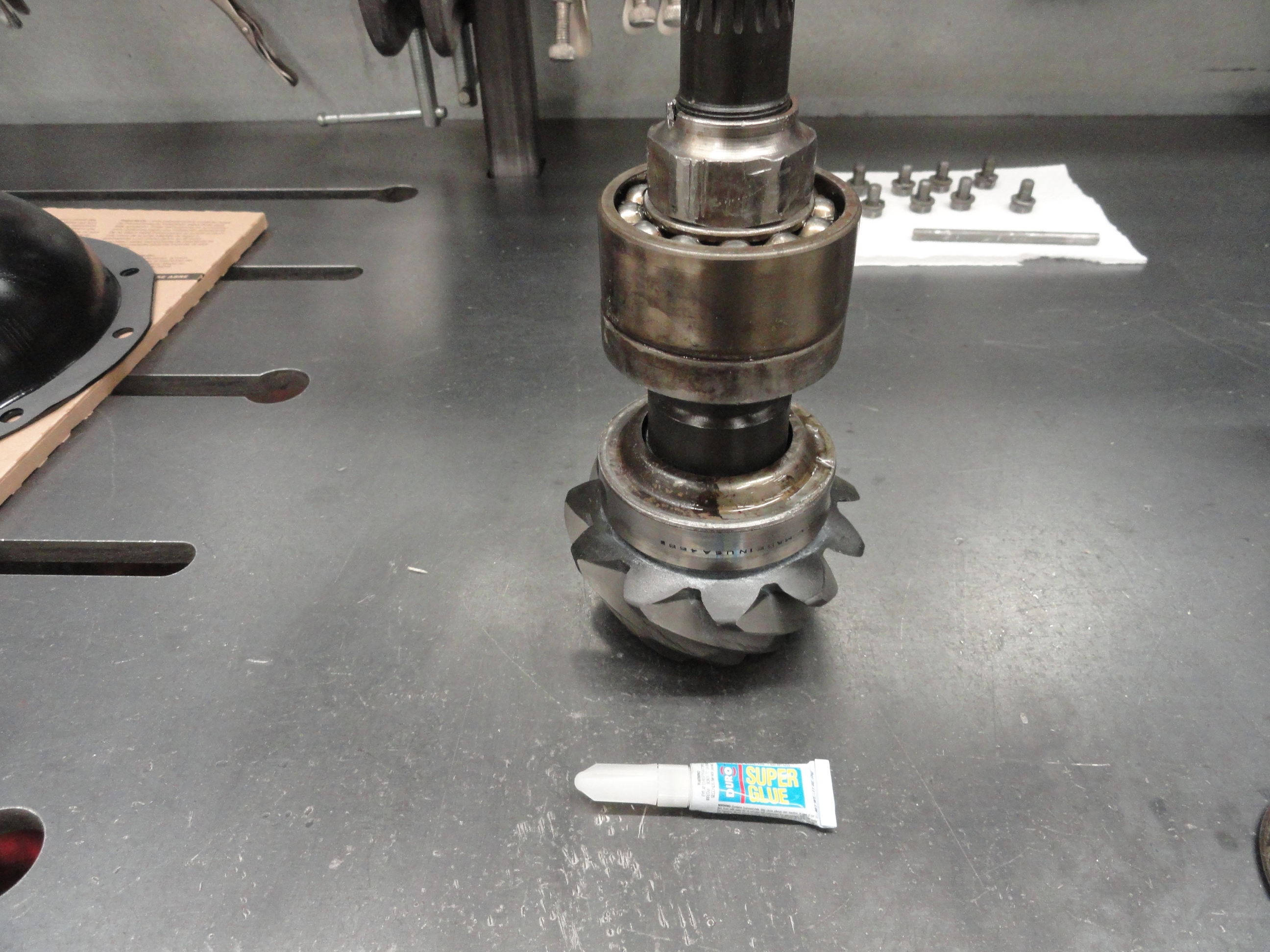
Important Tip: The Pinion Retainer (that ring that slops around on the shaft) is going to give you lot of trouble when trying to get the assembly back in. Problem is, gravity and some luck in 'bouncing' it into place is how this is normally done. I prefer an easier method because it has been known to take about 10 times of replacing shim stock to get just the right pattern on your ring gear before getting this right.
In/OUT/In/OUT ad nauseum and I can't imagine having the patience for that, so... With some Super Glue, coat the edge of the retainer that mates up to the Front Bearing (the thick one) and glue the ring to the bearing. You will need to very thoroughly clean the surfaces for them to stick together. Add a little clamping force and come back in 10 minutes to try it. Do not get glue into the bearings, just to the outside. Be careful in applying this.
With the Pinion Shaft equipped with all of its parts, let's install it in the Truck first without the driveshaft. Now is when you see if your Super Glue Plan worked out or not. Before attempting to install the Pinion Shaft, be sure everything you can reach is very clean inside the hole. I like to spray Lithium Grease in there just to be sure everything is slicked up good beforehand. You can use Gear Lube for this too.
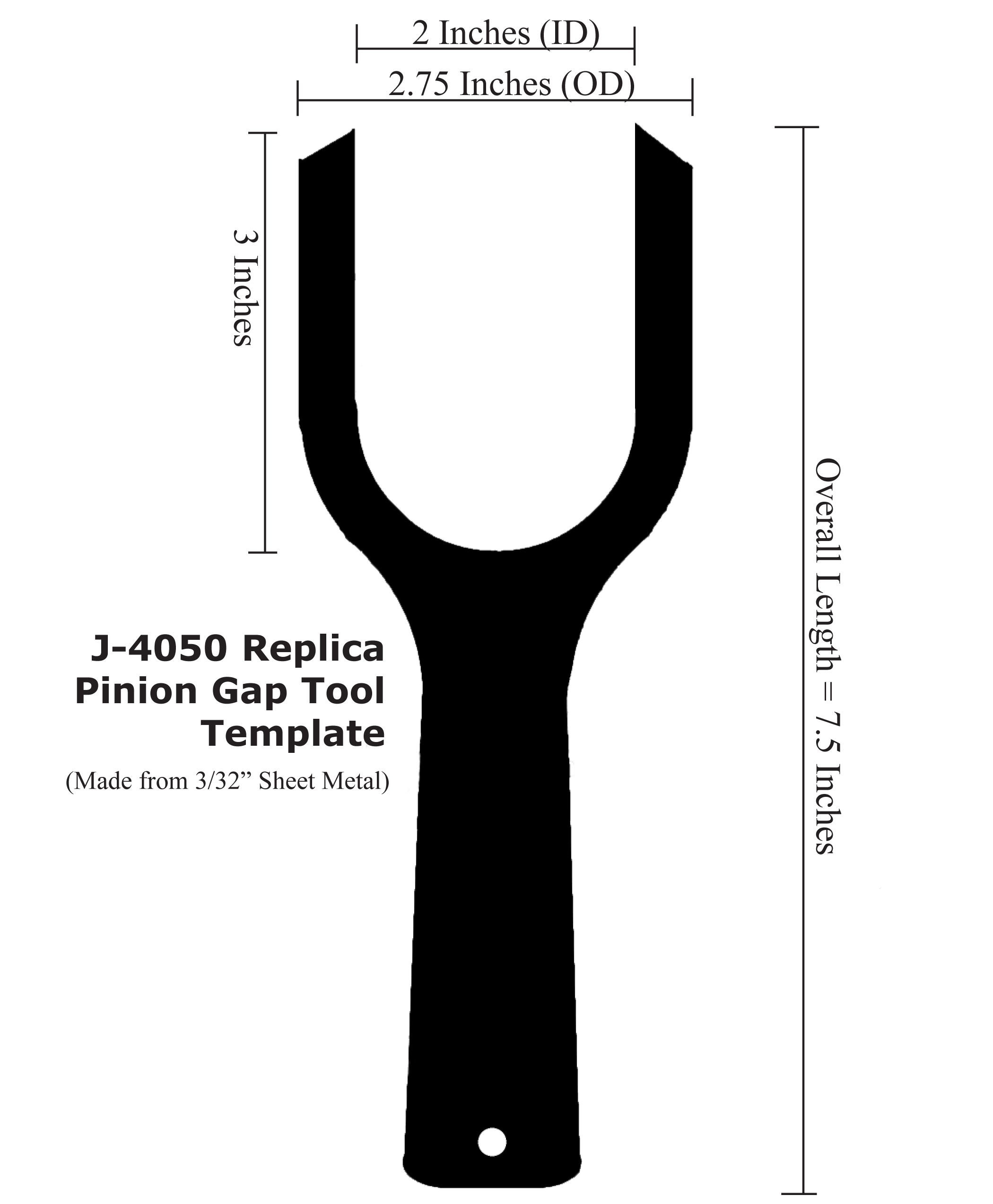
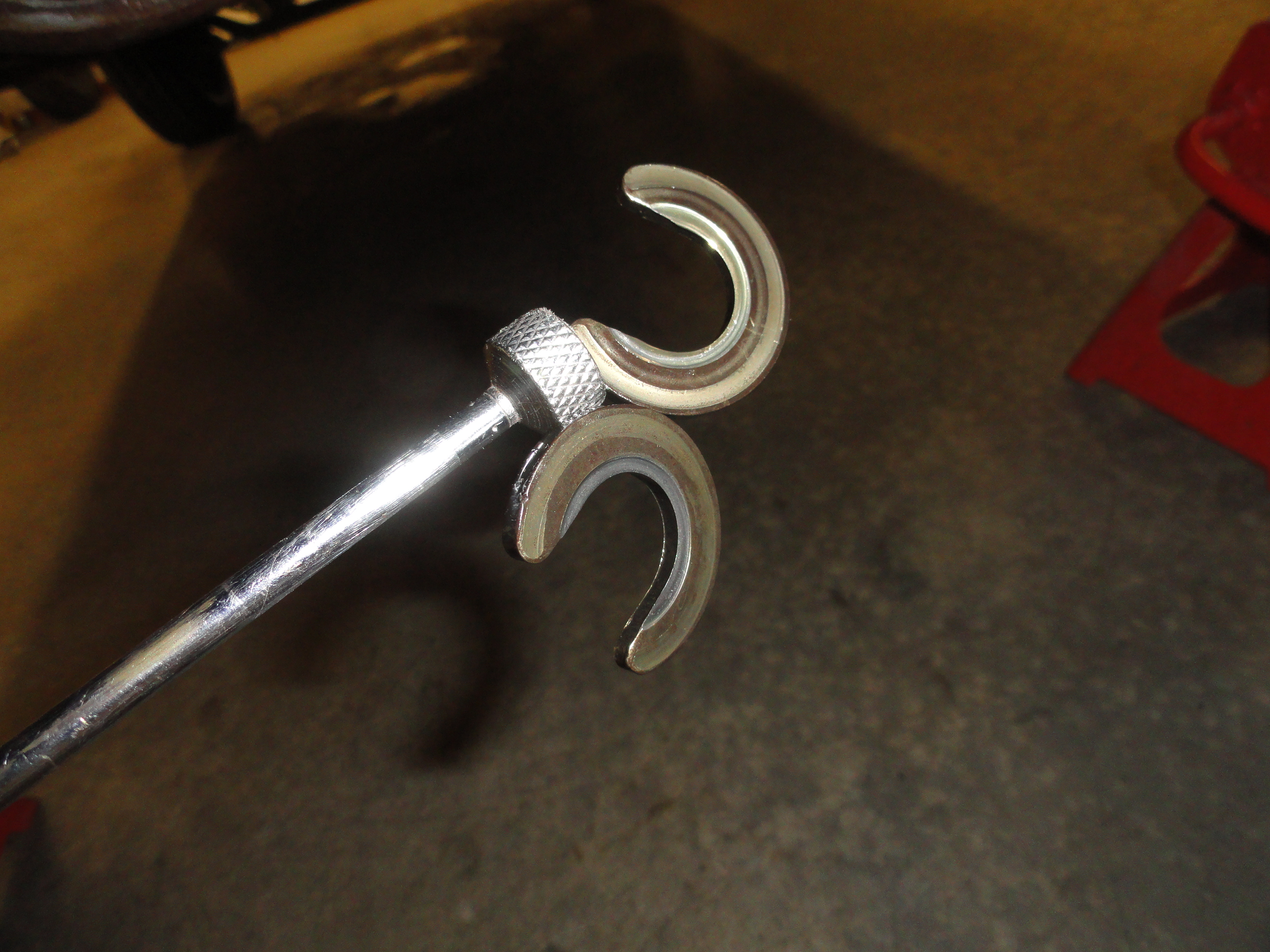
Print the Large Version (click on the small one left) at 100% to your printer, then cut it out and use as a template to make your very own Gap Tool. Use a piece of 3/32" steel plate. Nothing to it right? This template comes from an original tool, so you simply cannot lose! Take a look at the Slide Show at the top of this article to see how it is used and how to bend it. Remember.. Computer Printers come to you with a 98% printing setting. You will need to go into your print settings and change that to 100%.

With everything assembled on the bench, let's get these new parts in the Truck. We will add a .010 shim to our Shim Pack to start. This is because Dave tells me that is a good starting point to minimize taking the Pinion in and out. Put a little grease on the shims to hold them together and to the back of the Front Bearing. Put some fresh gear oil on all of the surfaces on the inside of the cavity so things are pre-lubed, then slide the assembly into place. If luck is with you, the assembly should go all the way in without much effort.
To test to see if you got it right, shine a flashlight into each of the three set screw holes on the outside of the differential. You should see the inside edge of the Retainer Ring. The best way to proceed from here is to drop a very small screwdriver into the top two retainer holes from the outside. This is to keep that retaining ring from moving forward. THEN, using your fancy new J-4050 Pinion Gap Tool, slide the forked tool behind the Pinion Gear and be sure the Rear Bearing that is up against it, is spread away from the gear by the width of the Tool. With the tool in, install the bottom set screw first, then the top two very loosely. This is when you remove the J-4050 Tool, then tighten the 3 set screws to 30 foot pounds and lock them in place with the locknuts. Remember, you are doing all of this without the main driveshaft in place just so that we can measure and test the Backlash and Pinion Depth for accuracy before installing the Driveshaft!
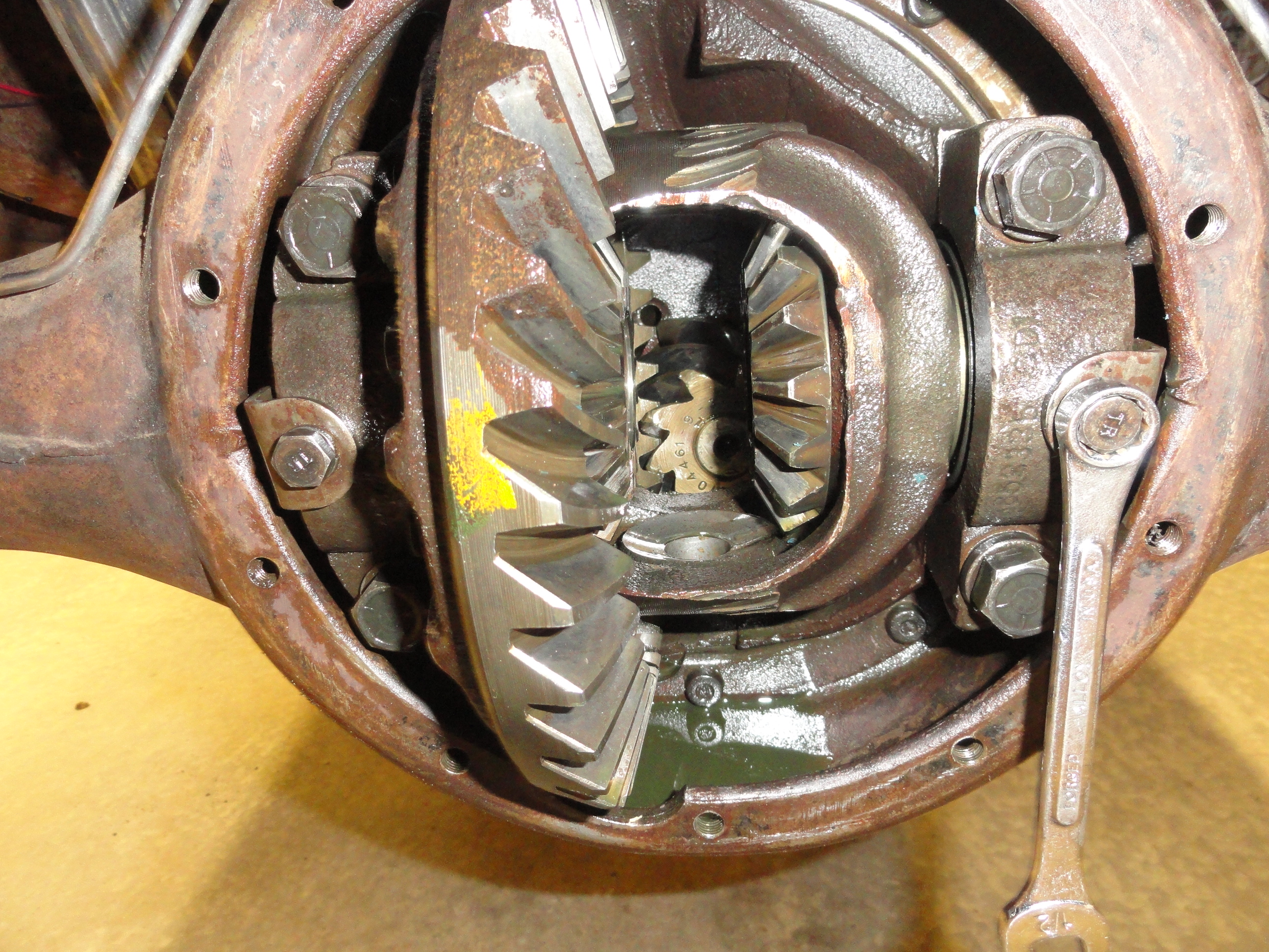
We will install the Carrier Assembly but not the Spider Gears, Axle Retainer Block, etc. because we are doing all this for ensuring the tolerances for backlash and Pinion Depth are secured. Some rear end carriers have shims at the left and right of the carrier. Not so here! This is a far superior system in that you can adjust the backlash LEFT and backlash RIGHT settings by simply turning the threaded adjuster. Set the Assembly into place with the Bearing Outer Ring and the Threaded Adjuster in place as shown. Put the Right Side Retainer Caps into place and start the threads to tighten. Do the same on the Left side but leave everything very loose.
To get things in the ballpark, put the threaded adjuster even with the outside edge of the both left and right caps. With the outer Bearing Race against the Inner Bearings, slowly tighten the Bearing Cap Screws. Tighten all 4 screws at the same rate and test your work by rotating the Carrier Assembly and watch the Pinion Gear move smoothly AND the Ring Gear move smoothly too. Once all 4 bolts are tightened to a point where the lock washer is starting to smash, check for smoothness in movement. Also start to think about Backlash and if the Carrier is too far Left of the Pinion Gear or too far Right. We are very close to checking Backlash and Pinion Depth. Very Exciting Stuff eh?
With no binding and the Carrier Assembly smoothly rotating, with the lock washers not smashed at all, loosen just a bit more and then try to rotate the left bearing adjuster. Without a special tool available, I use a large flat screwdriver and a hammer strategically placed to move the assembly. Tap around this assembly to ensure it moves as you would expect. You want both sides to move freely so you can adjust it correctly.
Loosen the right side adjuster enough so that it does not interfere with the left sides ability to push up against the pinion gear. Tighten the left side adjuster until it gets relatively tight, then back it off a few quarter turns and check for backlash. Backlash is the term they use to describe the dead space where there is no movement of the secondary gear when you move the primary one. Since the number is so small, we use a Dial Indicator for this. We need about .005 to .007 of travel from front to back before engagement. With the Pinion Gear shaped the way it is, you get more backlash as you move it further to the left and less moving it to the right. So to get less, be sure the right side is loose enough to let you move the assembly to the right, and then turn the left adjuster. More would be loosening the left adjuster and tightening the right. This is a pretty critical adjustment, so be sure you can easily feel the slop they call backlash.
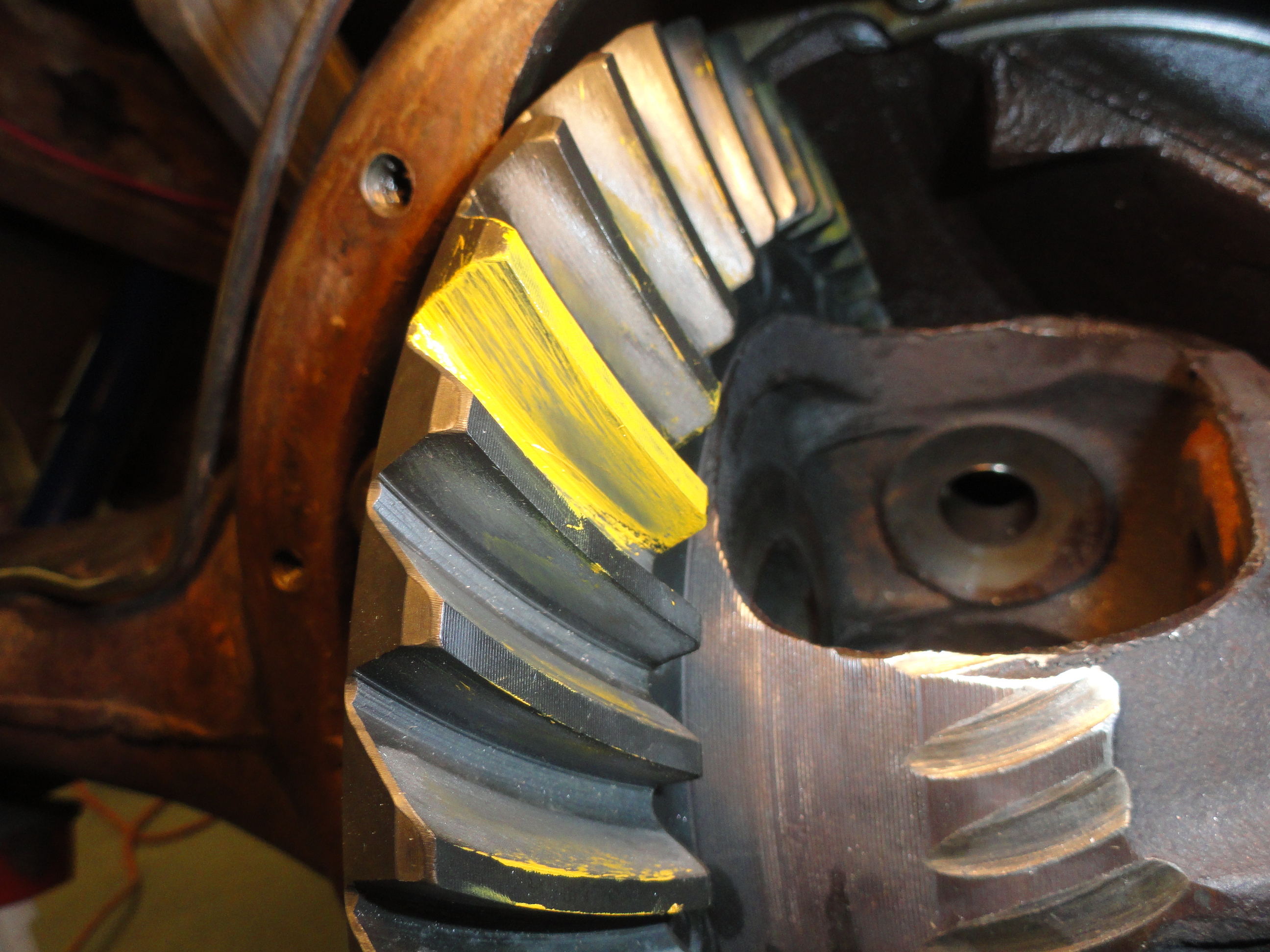

With the proper backlash set and the HOPE the proper shims were installed, it's time to paint a few teeth and see where we are. The original setup on this particular truck has a .015 and a .018 shim already installed. It was suggested to start with an .010 additional shim so now we will test the wear pattern to see how close we are. As you can see from the pictures, we are close, but not close enough. The picture on the left is the Drive Side of the tooth and the picture on the right is the Coast Side. An ideal pattern for the Drive side would be the marks to be closer to the middle which tells us we have too much shim. To see how it should look, take a look at slide number 57 in the filmstrip above. So much for luck being on our side. Time to take it all apart again. You can expect the superglue to break free and have to glue it again, but other than that, it's not all that difficult. Be sure to torque those 3 set screws to 30 foot pounds once you are sure the retaining ring is on the proper side of the set screw holes. (The Superglue held!)

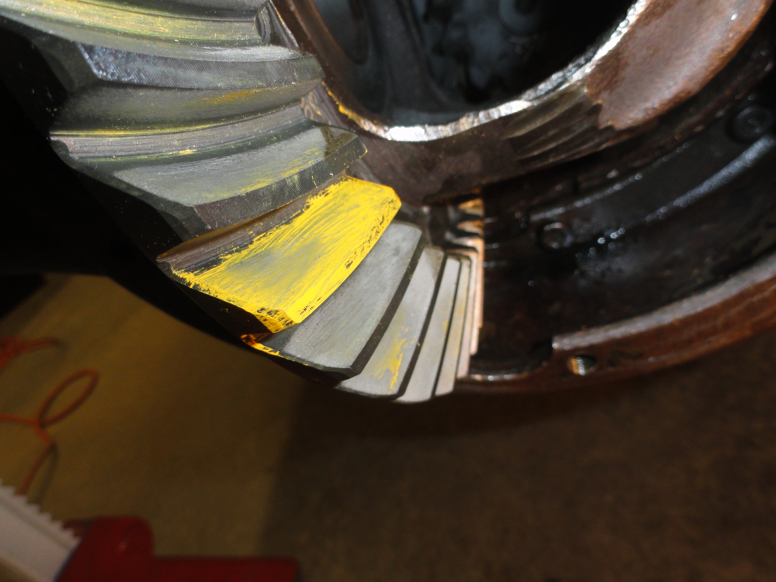
This time it was suggested we remove between .003 and .006 to see what happens. I removed the .010 and then added a .005. That resulted in the wear patterns in the pictures left and right. It is a very good thing I have my expert Dave to look over the pictures and tell me what he thinks. Turns out, this wear pattern is pretty much what you can expect when there is no Load put on the Pinion Gear. To get these wear patterns, it is important to put SOME load on them so take a stick (back of a hammer) and push against the pinion gear from under the Carrier while meshing the gears together both forward and reverse to get the best pattern. This still isn't ideal, but we do not have the driveshaft in yet to give it the proper load.
With the wear pattern ironed out, it is time to take it all apart once again so we can install the driveshaft. Take a file and run it over the splines at the front of the driveshaft to eliminate any burrs. Clean it real good and then we can turn our attention to the 5/16" pin that holds the Pinion Gear Assembly to the Driveshaft. This goes together really easy. Be sure to line the two holes for the pin up and then push the Pinion Assembly into the Driveshaft and line up the holes. I used a 5/16" Pin Punch for this. Cut yourself a piece of 5/16" steel dowel about 1/2" longer than needed to go through and hammer it in place. Place the joint on top of the vise or anvil so when you hammer it down, it creates a mushroom effect so it cannot go through the hole on one side, then turn it over and do the same on the other. See Slide 39 in the filmstrip above. If you have to cut a little more off, do so to get it just right. Peen the other end so that both sides cannot go through. With it tight and secured, that is all you need to do. There is no pressure on this pin so it is only there to keep front to back movement in check.
There are no pictures in this section because this is just a reversal of the removal. With a clean driveshaft and everything installed on the Pinion Assembly and superglued correctly, time to get under the truck and push the entire assembly into position. I installed the shims first with a little grease on them to hold them in place inside the back of the hole, then carefully (like installing a camshaft) slide the driveshaft up into place. There will be some resistance getting it through the spline at the transmission end, but nothing a hammer handle cannot persuade into position. Before driving this assembly all the way in, install your J-4050 Fork Took in between the Pinion Gear and Rear Bearing. Doing it now will be much easier. Finish driving it home then check the 3 set screw holes to make sure the Superglue held and the Retainer Ring is forward of the setscrew holes. If it is, stick a small screwdriver in one of the top holes just in case, then remove your J-4050 Fork Tool and install the 3 set screws. Torque them down to 30 foot pounds as before. This sets the Pinion Assembly and Driveshaft in the correct position. If it rotates freely (in neutral) then you probably did everything right.
Again, no pictures because it's the reverse of what we did before, but this is where it is important to make sure you get the Outer Carrier Bearing Race and the Adjusters in evenly and then make the Left/Right Adjustments to get the backlash as described in Step Fourteen. With .005 to .007 of backlash, torque down the 4 Carrier Assembly Bolts to 110 foot pounds. Check the backlash once more to make sure nothing changed.
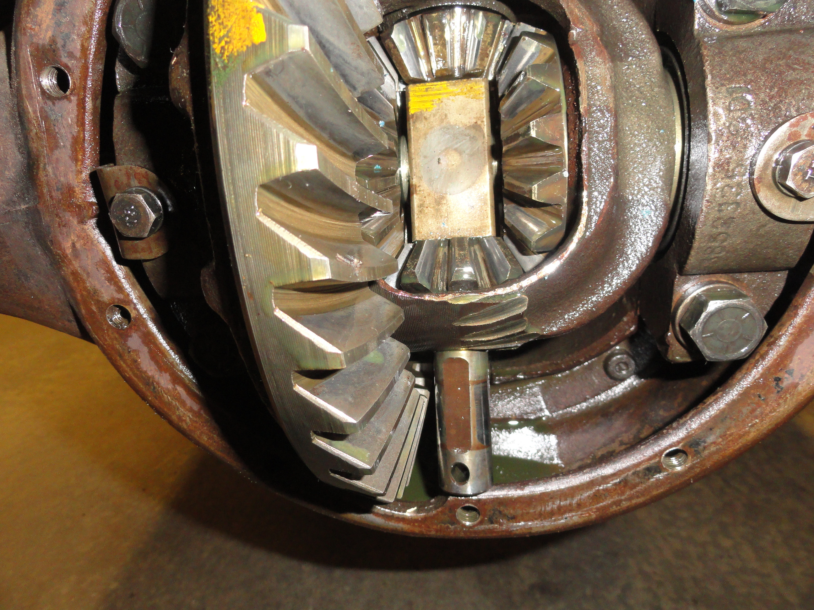
All four of the spider gears are interchangeable and I like to swap positions to get a more even wear of the components. Put what was left on the right side and put what was up on the down side. These gears slide into place easily but do not smash your fingers. With the Carrier turned so you can see everything, just slide them into place. With the two left and right gears in their slots, install the Axles. Always hold something like this the same way you would a camshaft to avoid putting too much pressure on your new seals. Once they are slid all the way in, put a C-clip in each side and push the Axle out to keep the C-Clip in place. With the Axles secured, install the other two spider gears. The two free gears will need to be exactly across from each other for the Axle retaining block to go in. With the gears installed across from each other, put the Axle Retaining Block in place and put the large Pin through the hole. One end of that Pin has a locking hole that mates with the Locking Bolt so be sure to install it the right way. Once the Pin is aligned with the hole, Bolt in the Pin Locking Bolt and tighten securely. Rotate both axles to see that everything turns freely. Also rotate the Carrier (vehicle in neutral) to see that everything turns as expected.

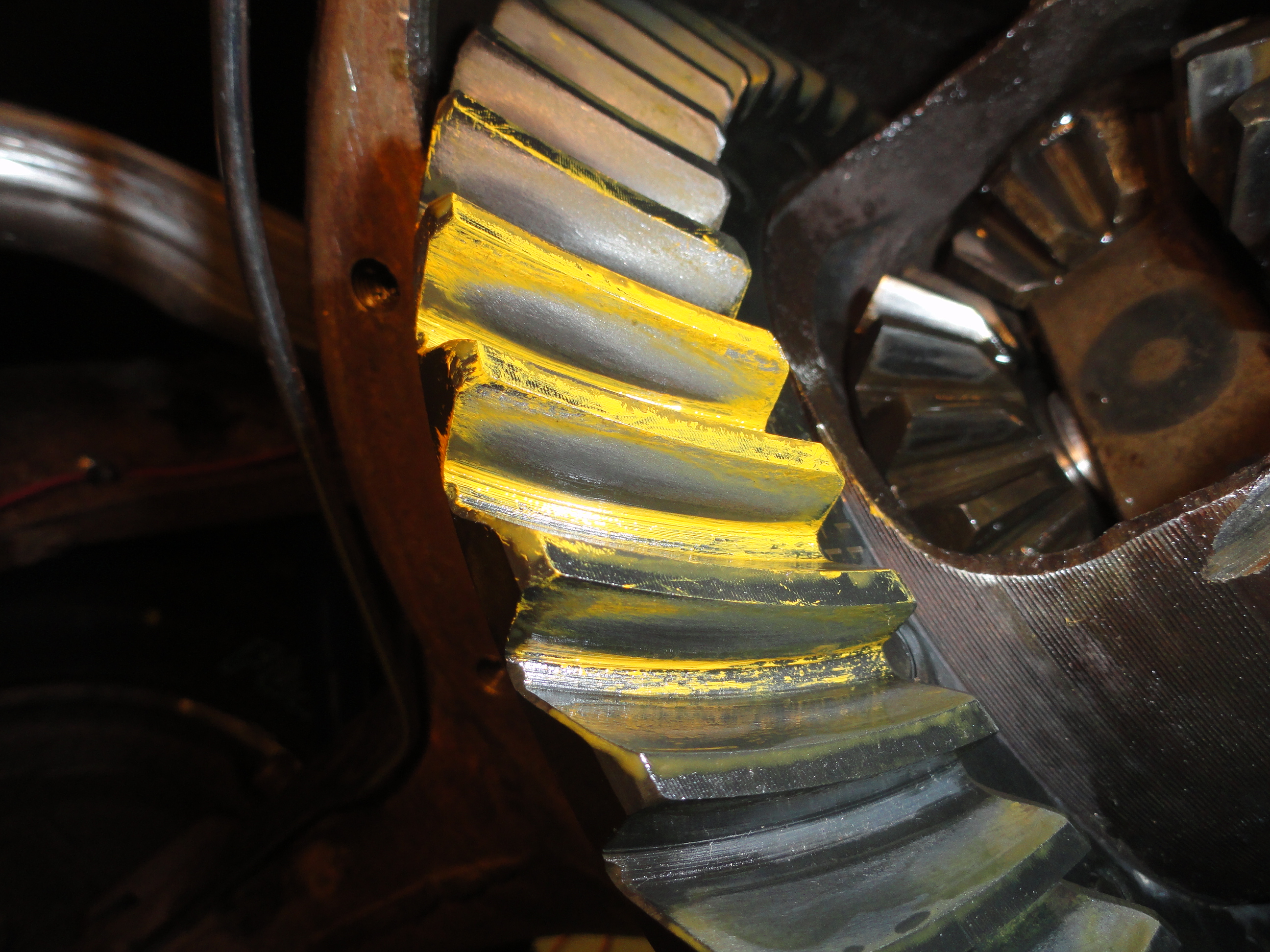
With everything secured and all tools out of the way, let's check for a proper wear pattern under load. With the back of the truck jacked up so the wheels are not touching the floor, brake drums reinstalled and adjusted, we need to load the pinion down. Paint the Yellow Gear Paint on a few of the teeth on both sides. Paint ALL of both teeth. Start the vehicle and put it in 1st Gear. With one foot on the brake and the other on the gas, hold the brake down while revving the engine just enough to hear the engine bog down a bit. Then put the vehicle in reverse and do the same thing. This only takes a few seconds and will give you your final wear pattern as shown left and right. As you can see, putting a load on the gear system makes a world of difference!
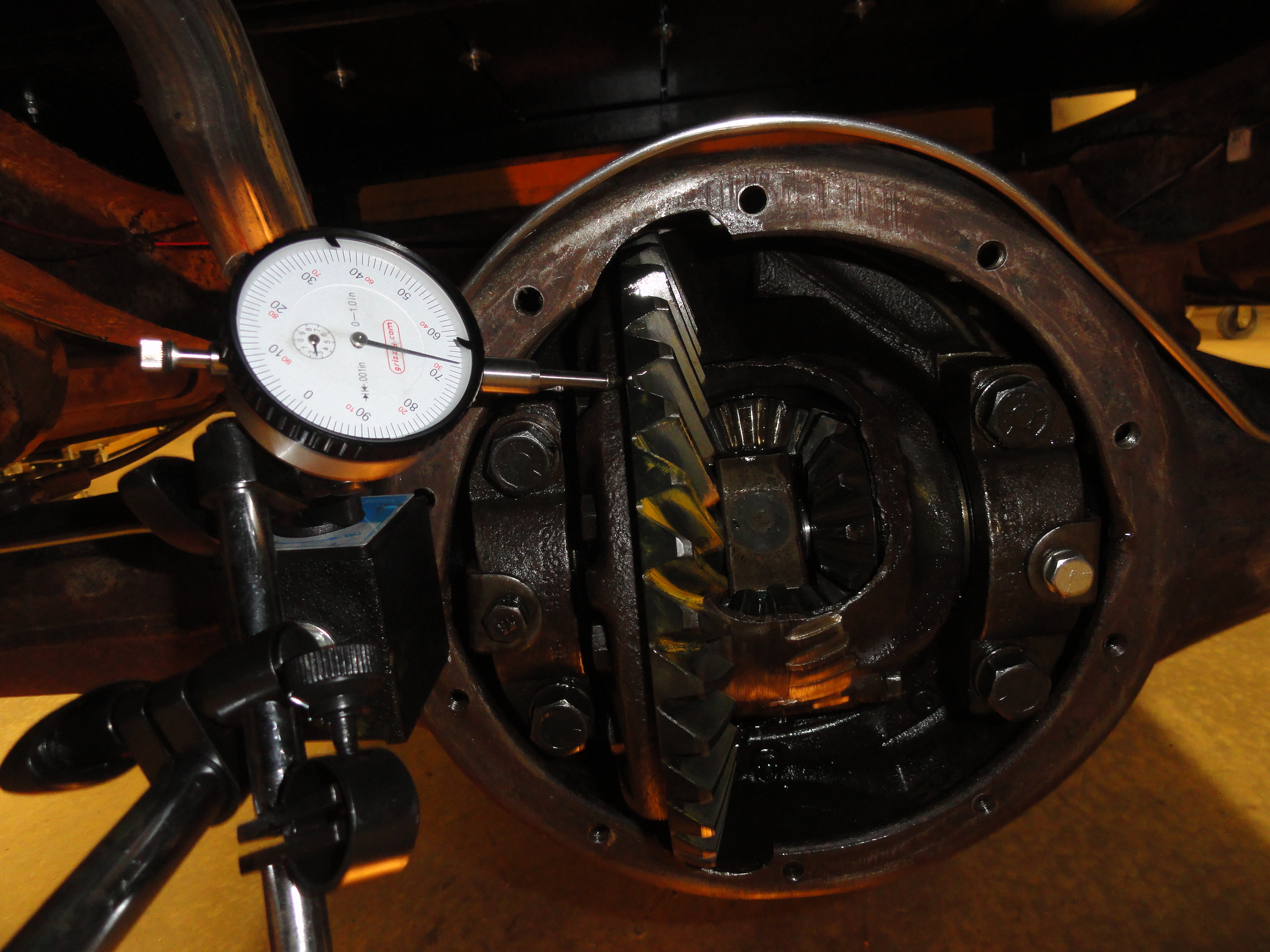
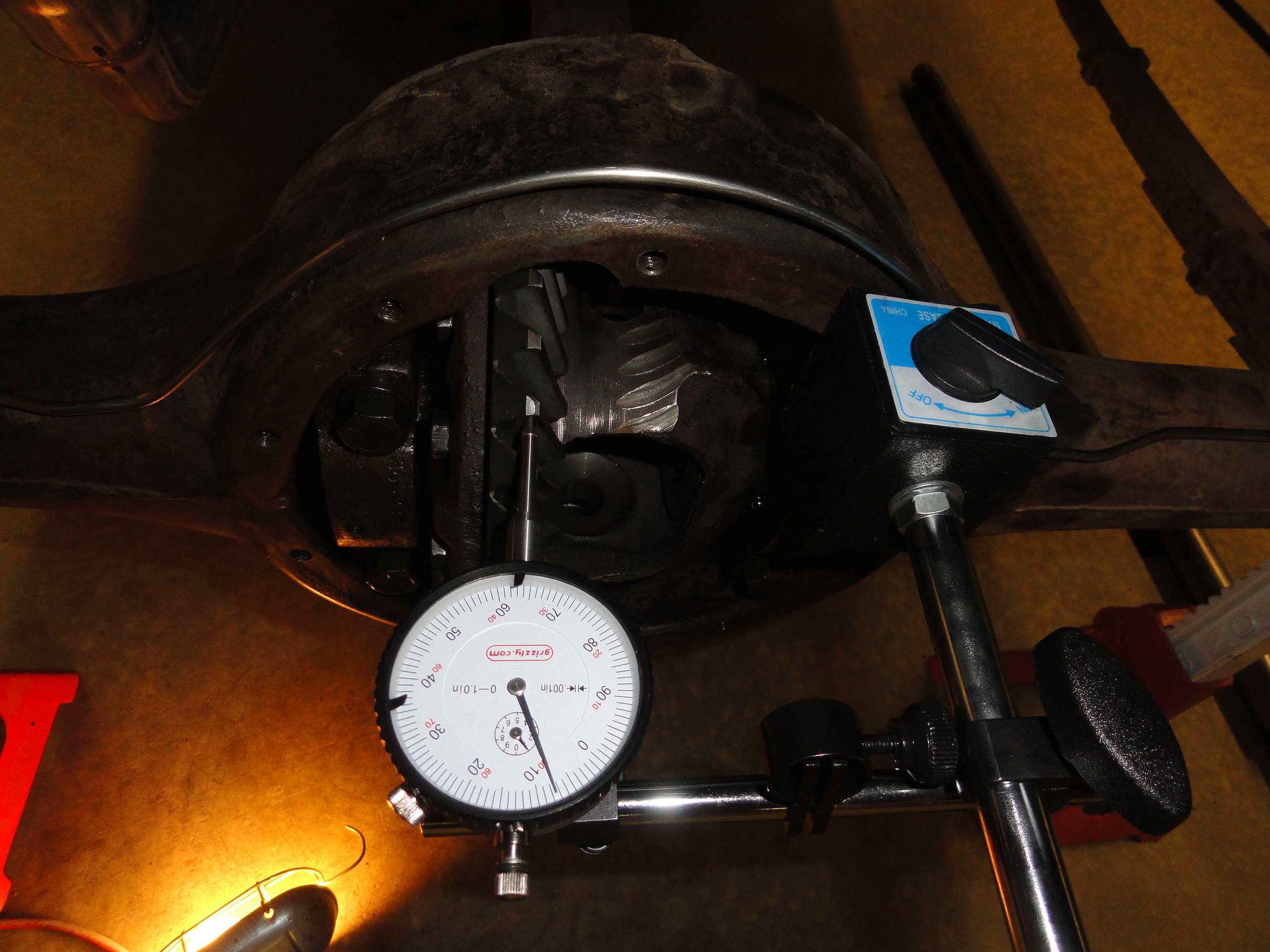
The final check before buttoning up the Differential is to check the Carrier Ring Gear for Run-out. Run-out is basically how TRUE does the gear run? If there has never been any catastrophic damage to the Differential and you installed the Ring Gear properly, this check will pass. Install your Dial Gauge as shown to see if the needle moves when rotating the gear. You are checking for wobbling of the Gear. There should be no more than .003 difference anywhere.
With everything properly torqued to specs and everything installed and working smoothly, clean out the inside of any debris and run a magnet through the case to make sure there is no magnetic debris then install the Differential Cover. Use the proper gasket and use gasket sealer so you do not have leaks right away. Install a good 90 weight Gear Oil and you should be good to go.
So happened the weather cooperated on a rare Kansas day with little wind and 78 degrees, so Vietta and I took it out for a drive. I had a smile on my face the entire trip! Even at the end! With no Tow Truck or anything! Seriously though, it was odd at first how the gears shifted differently. The Speedometer is WAAAAY off. At 22 on the speedo you are actually going 30 and at 43 on the speedo you are actually going 60. I need to look into that. At 60mph on the GPS, I was doing 2550 RPM which is exactly what the calculator said it would be. We drove around the rural Kansas countryside enjoying the day and everything worked famously. Just be sure if you tackle this that you are meticulous and have a mechanical mindset. After all of this, I would say it challenged my talent set pretty good in places. Thanks yet again Dave! Dave is amazing and if he can guide me through it from 2000 miles away, we can do anything. Collaboration is what it is ALL about! Kudos to Brad Allen for taking the time to get that film strip ready as well. On to the next challenge!