


Deve's Technical Network
1947-1955 1st Chevy Trucks
216/235/261 Engine Solutions & More
Conventional Wisdom; Ideas, Opinions, or Understanding that are to be generally accepted by the public. In the case of our vintage vehicles, you don't have to go too far to find someone with a differing opinion on just about everything. Much of the disagreement comes from life experiences we have had that give us the confidence to say with conviction that we are correct. The problem with this phenomena is that these differing opinions cause all sorts of social problems that can be avoided if we take a second and third look at the issues. All of the subjects covered here on DevesTechnet are proven using math and science. The enemy of everyone trying to do something worthwhile is conjecture. So in the following document, you will learn how to make all of the systems on your vintage vehicle 'Native' 12 volts. This document is for people with vehicles prior to 1955 that came from the factory as a 6 volt system. Even if you have already upgraded to 12 volts, this article is for you!
So what is wrong with 6 volts you might say? 6 volt systems require 2 times the current carrying capacity of a 12 volt system. This is why you must use 2 gauge battery and grounding wires on them rather than the 4 gauge that 12 volts uses. At the time they were created, battery technology was poor to midland and in cold weather climates, this caused much grief, especially with farmers, or businessmen trying to use their vehicles for Commerce. The starter runs anemic under 6 volts, lights are dimmer, and until the advent of the Optima Battery (and just better technology), people were left without transportation on a regular basis. Don't take my word for it, when was the last time you saw a new 6 volt vehicle? For Chevrolet, it was 1955! Many farmers would just take the 8 volt battery out of their tractor and use it in cold weather. It was not a good standard, but for you stock enthusiasts out there, properly maintained, you can get away with it. I love a good stock vehicle that is 6 volts. I own two of them. But for a daily driver in Central Kansas, it's 12 volts due to the superior starting, lighting, and reliability.
This article is about taking your 6 volt vehicle, or even your upgraded 12 volt vehicle and making it 12 volts all the way through. Why would we do this? While it's easier to just use a big, high wattage resistor that gets very hot due to the power it must dissipate, it is not very efficient. High wattage power resistors work by transferring Power to Heat. Does this sound like a good idea to you? If wasting 50% of your power in any given upgraded system is okay with you, no need to read further. If having super hot resistors under your dash and on your firewall is not a problem for you, just follow conventional wisdom and do not waste your time with this article. There is an alternative and in doing some of these relatively low cost changes, you will have a much more efficient electrical system.
Aside from the misunderstanding that lead to positive ground vehicles, once it was determined that electrons are negatively charged and move through wire from negative to positive more efficiently and we all got on the same page, let's examine a typical GM 6 volt negative ground ignition system. The system consists of a battery, a switch, a coil, and a distributor. The distributor has two separate voltage and current carrying systems. The coil also has two separate systems that correspond with the distributor. They are the Primary and Secondary circuits. The primary circuit in the distributor is the points and condenser circuit, while the secondary circuit is the rotor and cap circuit. The Primary circuit in the Coil is the two terminals on the top of it labeled (+) and (-). The (+) is where the ignition switch is connected and the (-) is connected to the single wire on the distributor. The points opening and closing sends a signal to the coil telling it to fire at a precise time based on the 6 lobes on the distributor shaft and the point gap. The secondary circuit of the Coil consists of the large Coil Wire going to the center of the Distributor Cap.
What makes this relevant to our discussion is that there was no ballast resistor in a 6 volt ignition system. There was no need for it. GM decided it best for the sake of longevity of the points to keep the voltage at 6 volts. So everything was EVEN STEVEN back in the day! 6 Volts in, 6 volts out. THEN GM decided when they went to 12 volts something. (I don't know if they had a HUGE surplus of 6 volt parts, or they didn't want to spend the money reinventing the wheel). In any case, their decision to keep the entire ignition system 6 volts was before that, unprecedented. Native 12 volt systems clear into the 1970's still use a 6 volt ignition system! Rather than making parts such as points and condenser that would last when doubling the voltage, they incorporated a Ballast Resistor. This made sense because points WOULD burn up twice as fast and apparently it was just too big of an engineering challenge. The ballast resistor which comes after the ignition switch but before the coil and distributor meant that we can use 1940s 6 volt vintage points, condenser, cap, rotor and COIL on your 1972 C10 Pickup and it will run every bit as good as new parts providing the old ones are in good condition. Of course parts style differences and interchangeability prevent this, but you get the point. I have personally tested a Delco Remy 6 volt coil (stock number 1115380) from 1950 on a 12 volt 1959 235 test engine and it runs great. Why some of them have '12v' stamped on them is beyond me. The best I can come up with was because of the confusion. 12 volt vehicle owners mistakenly thinking they need 12 volt ignition parts.
This can of course be proven mathematically. A coil is basically a two stage transformer having a primary and a secondary. Since they work on the principle of induction, the ohm value of the totality of the windings in the primary is what determines how much voltage the points will see. In the 6 volt days with no ballast resistor, there was 1.5 ohms between the ignition switch and the points (give or take since there is some residual wire resistance). So Ohms Law tells us that in that scenario, the points saw about 5.94 volts at about 4 amps. This is the very same numbers we see today with 12 volts. With a 2 ohm Ballast Resistor, and the same coil, we get 3.5 total ohms and 12 volts. The formula comes out the same! The same is true for the secondary. 12,000 to 20,000 volts is a common OEM number.
Let's use more modern technology and get rid of that hot, paint burning, power resistor called the Ballast Resistor once and for all! If you haven't figured it out yet, I have
this thing about converting perfectly good power to heat. Enter GMs own High Energy Ignition System. The 6 volt, 12-20k volt coils are OUT, the new natively 12 volt, low
resistance 45,000 volt coils are IN. With wider plug gaps and a much hotter spark, we have a more efficient fuel burn at leaner fuel mixtures. And, we didn't transfer 50%
of our power to paint melting heat! With a higher precision computer controlled system, we have a much happier engine to boot! You can read all about it in the two articles
here:
1) How to Build Your Own High Energy Ignition System
2) How to Install Our High Energy Ignition Kit
To restore your vintage heater, I did a How-To article on the process I used that may be of help. You will find it here:
1947-1954 Harrison Deluxe Heater Restoration
As anyone who has tried to apply 12 volts to the stock 6 volt heater switch will tell you, it gets HOT. And yes, it gets hot enough to melt wiring, and smoke the fuse and the 10 watt resistor that is affixed to the switch. Let's not convert power to heat. Especially if you care about the longevity of your vehicle. That being said, the only way to change the RPM of a DC Motor (which is what is in your vehicle) is to step the voltage down (only for low rpm and medium rpm) using power resistors. This is pretty much unavoidable without going to power transistor solutions. But when we do such a horrible thing, we can use the proper wattage resistors which considerably lower the heat. Later in this article I will explain how to use a DCC Motor Controller that is our exception to the rule.
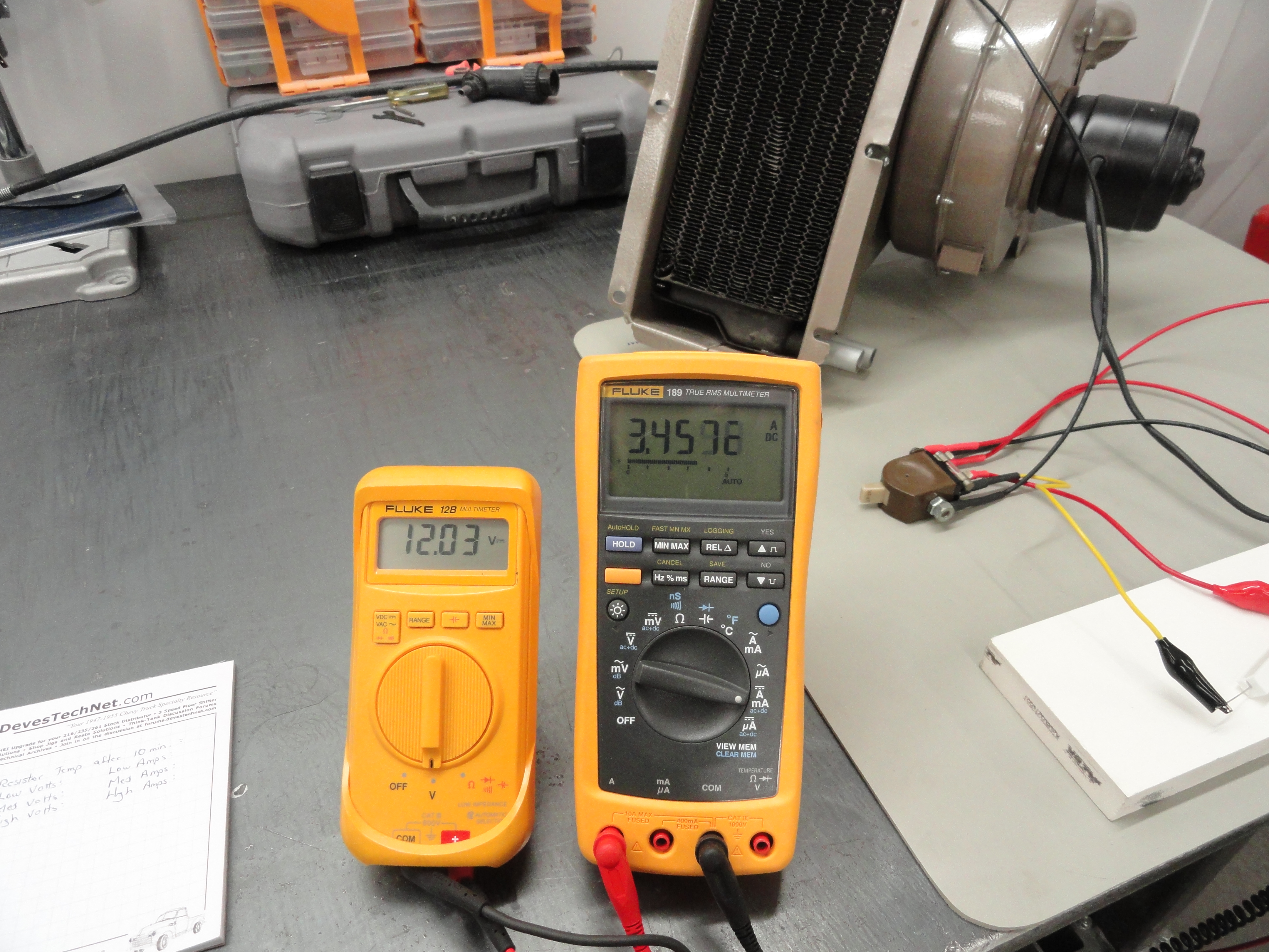
We have two electronic formula's to contend with in our determining which resistors to use. The Power Formula will tell us how many watts will be consumed and the Ohms Law Formula will give us the Resistance value based on Voltage and Amperage. All we need is to know a few things about our application. One of them is the Ohm Value of the motor itself. In our case the motor is 1.0 ohms measured across the positive and negative leads. Another thing we need to know is how many volts do we wish to step down to for medium and low. We can gauge the speed by focusing a Laser Tachometer on the motor shaft. So let's plug in some numbers!

For stepping down the 12 volt motor in low and medium we will use the following numbers. These are real numbers taken off the ammeter and voltmeter during testing. This was complicated by the additive nature of the resistors, but after some testing these were optimal. The RPM is really an afterthought since the voltage/amp values will exactly follow RPM percentage anyway.
RPM numbers are approximate because each motor is slightly different.
While these numbers seem pulled out of thin air, they all share resistance values we can use efficiently by combining ohm values to get the result we need. Since the motor is 1 ohm, we will do it just like GM did it with the original resistor that was on our switch. We will divide and conquer! While in the LOW switch setting, both of the resistors are being used. While in the MEDIUM setting only the 1.5 ohm resistor is used. High setting uses no resistors. On the High setting 100% of the voltage from the battery is used to power the fan motor. There is a myth out there that says resistors are used for current drop, NOT voltage drop. Whoever said that first was a genius because they got a lot of people convinced we can't do what we are about to do.
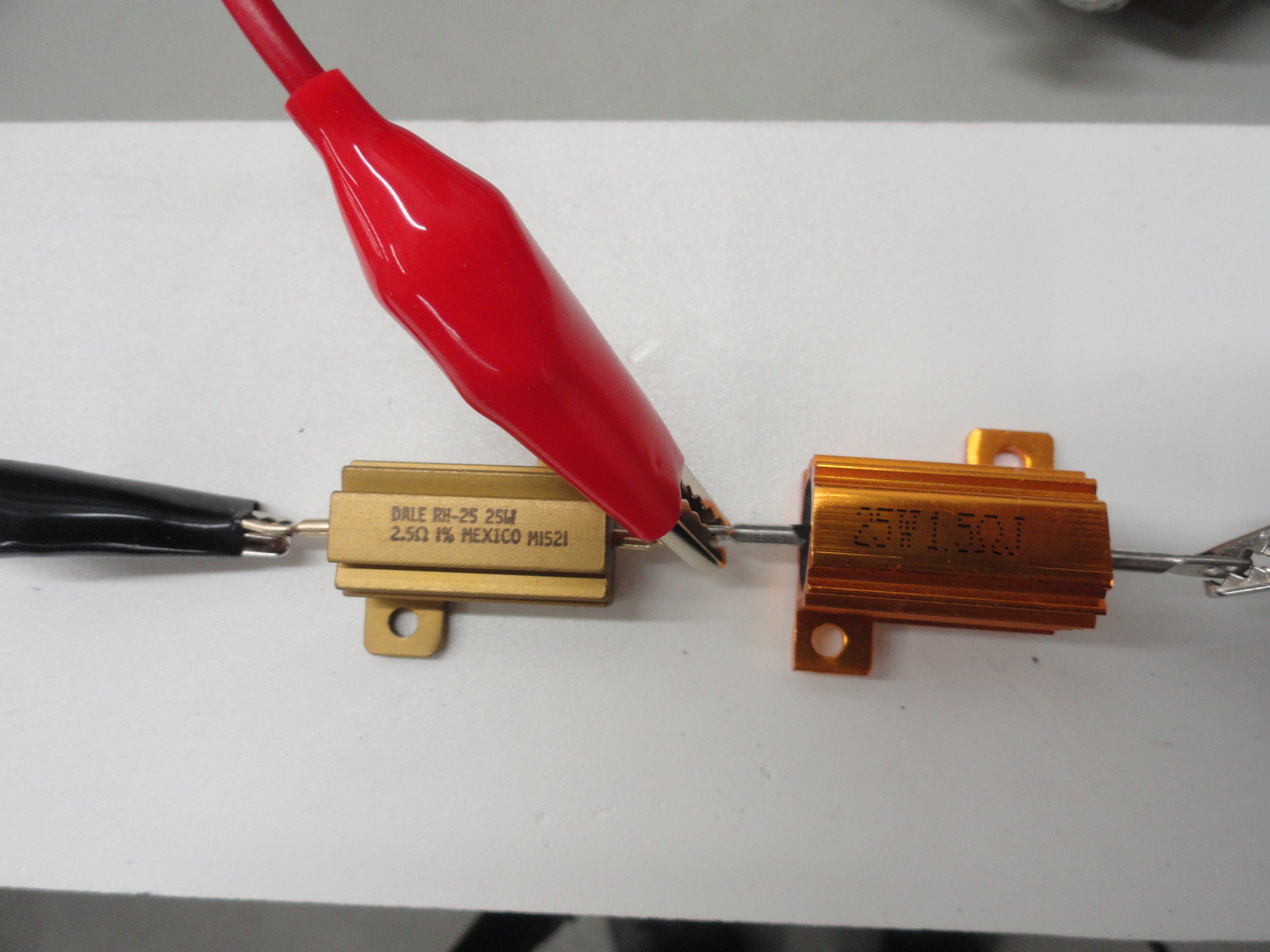
Remember how HOT that original equipment 6 volt switch gets when you apply 12 volts to it? This has to do with our Power Formulation. Power is voltage times current. It gets complicated mathematically because every time you change a parameter, the wattage changes with it. Suffice it to say we need to make sure our resistor array can handle at least 18 watts. Since the original 6 volt resistor on the switch was 10 watts, it's no wonder it generated that much heat. To make sure we never have a wattage problem, we will simply use quality 25 watt metal shielded power resistors. They are less than $3 each so why not go overkill. Resistor Wattage Rating means how many Watts can you push through that resistor before it fails. For our purposes we have 7 Watts to go before failure which will never happen with a 14 amp fused switch. They also have mounting holes which will definitely come in handy later. Remember why we are doing this. We are going to a native 12 volt motor and using 12 volt rated resistors. This makes the entire system much more efficient and will not generate anywhere near the heat that would destroy paint, wiring or components.

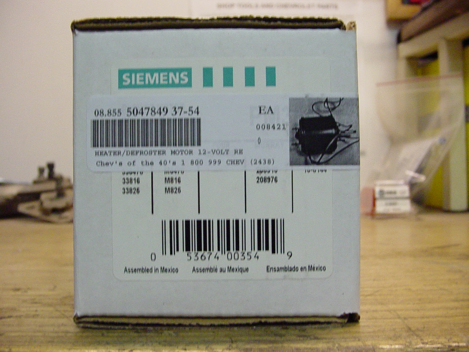
The Motor - To this point we have been discussing the switch and step-down resistors. The main component to this new system is the 12 volt motor. There are issues that
come with switching to a 12 volt motor such as the way it looks in the vehicle. On an Advance Design (1947-1955) Chevy Truck for example, the wider 6 volt motor was an integral
part of the firewall and the hole size and fitment matters a great deal to the finished look. This is less of a factor than most restorers think at the onset because the 12
volt motor fits inside the 6 volt motor housing very nicely. Be sure to remove the spot welded metal piece at the back of the shell and the 12 volt motor will fit right in just
as if it belongs there. The part number of the motor is PM-354 made by VDO or Siemens and available most anywhere. To see exactly how to accomplish this modification, I added
some more detail to the main Heater Restoration page. Go here to see how easy it is and while you are at it, check out the new Ranco Heater Control Valve instruction that is
there too!
Routing the Harness - Most of the engineering for our heating system is complete with the exception of where to put these 25 watt Power Resistors. They do not need to be near the switch but we need to make a special harness that incorporates our new design. A logical solution is to mount these two resistors inside the air stream when the fan is turned on. It would help keep things cool and they would be completely out of sight. The heater switch is normally located near the steering column which is great for hooking up the power, but a little inconvenient for the 4 wires that will go to and from the switch to the Heater Assembly. Nonetheless, we will accomplish this cleanly and using 14 gauge wires so that our wire distance will play no role in this. The best route from the switch would be laying the harness on the inside ledge at the bottom of the dash across to the heater. This is how modern car heating systems are done. They put the resistors in the air stream to keep them relatively cool.
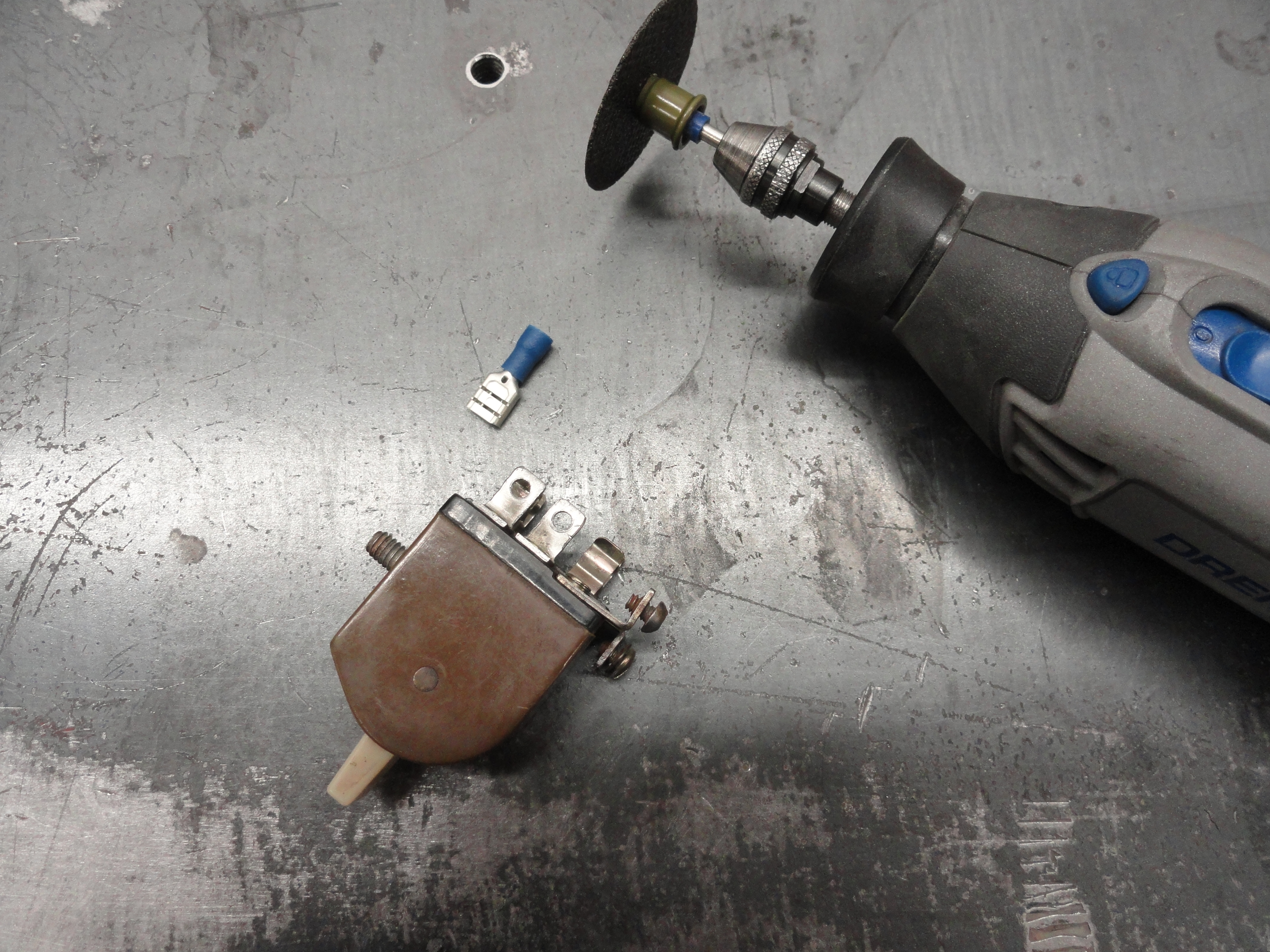
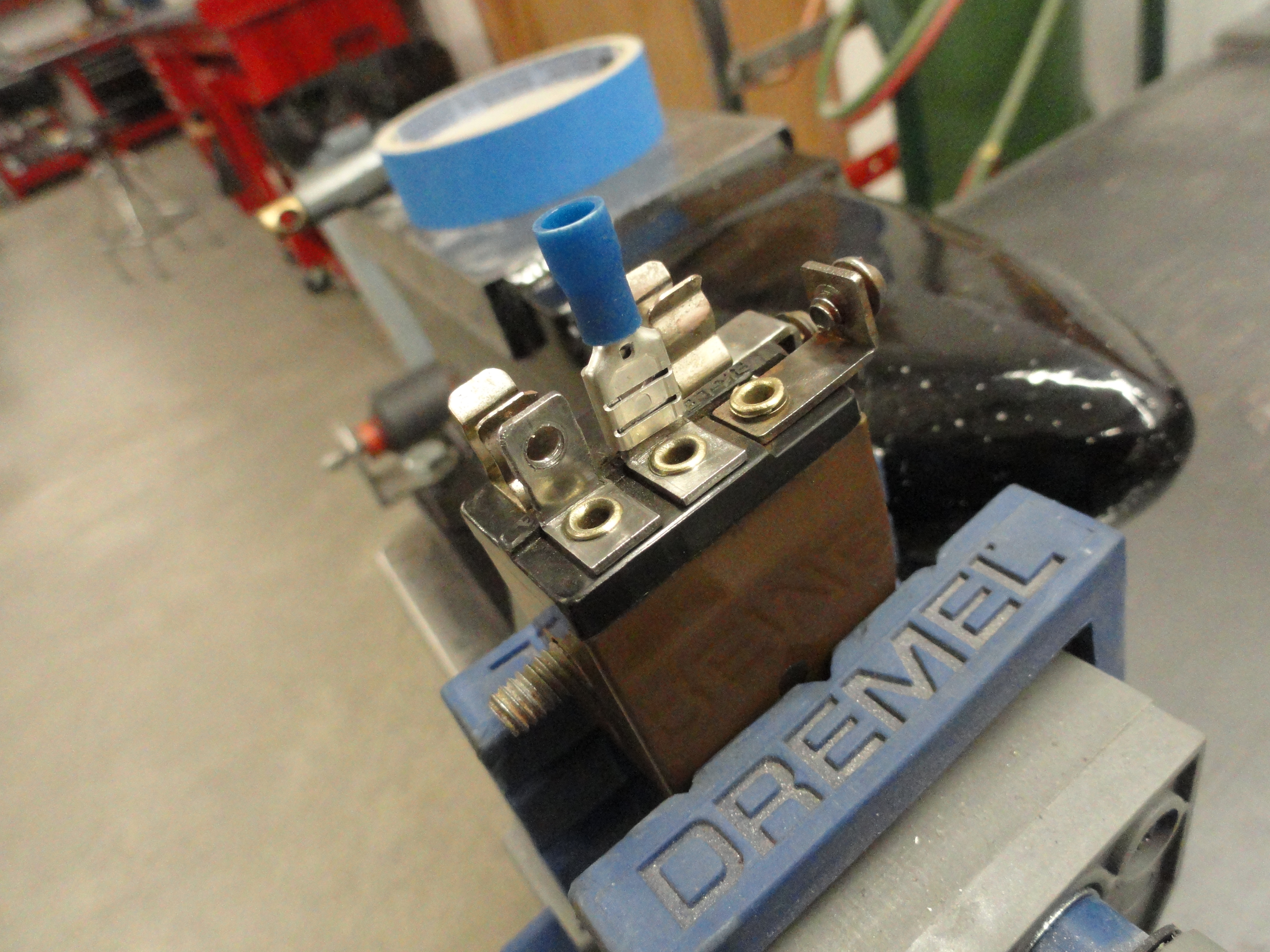
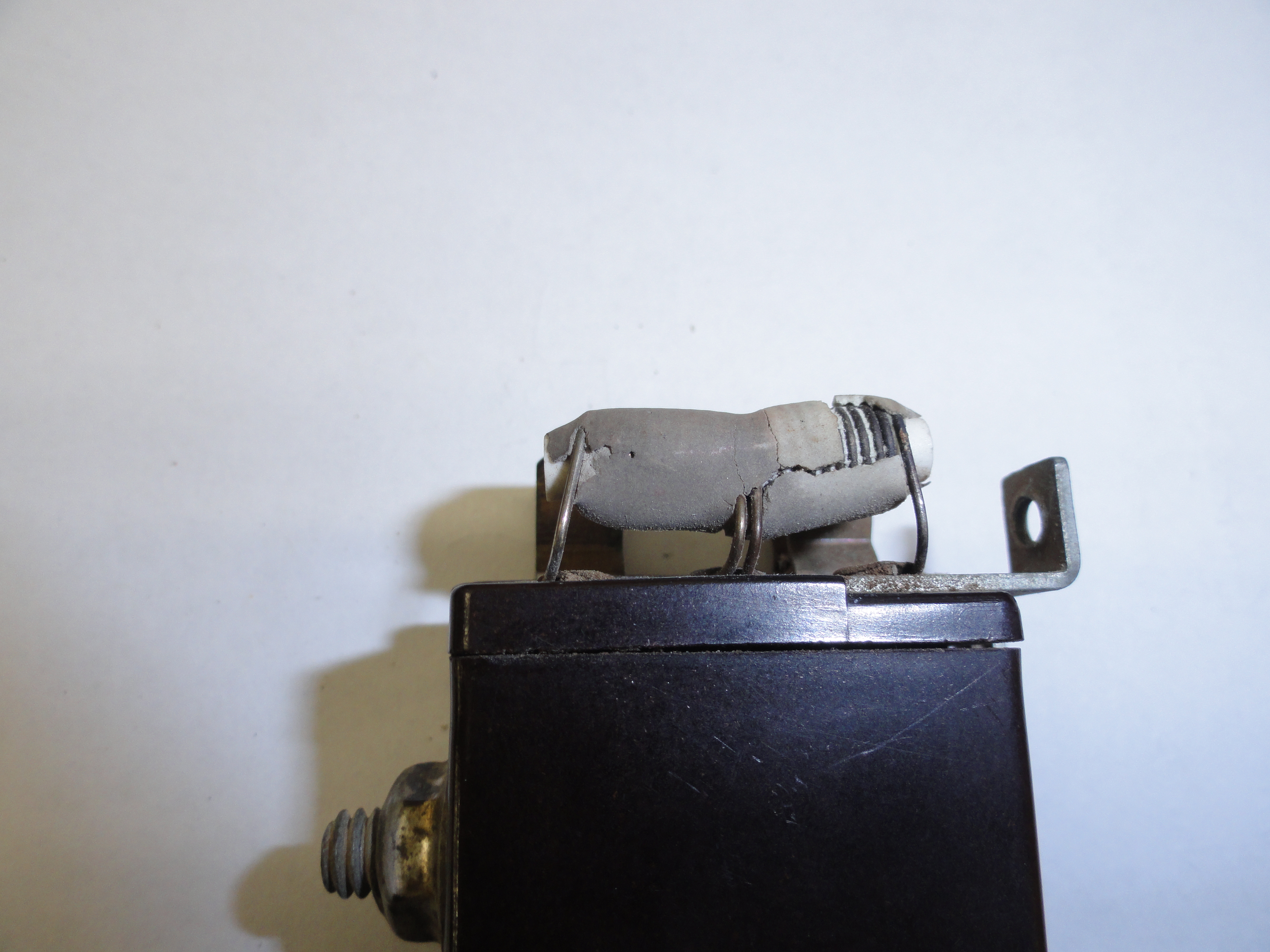
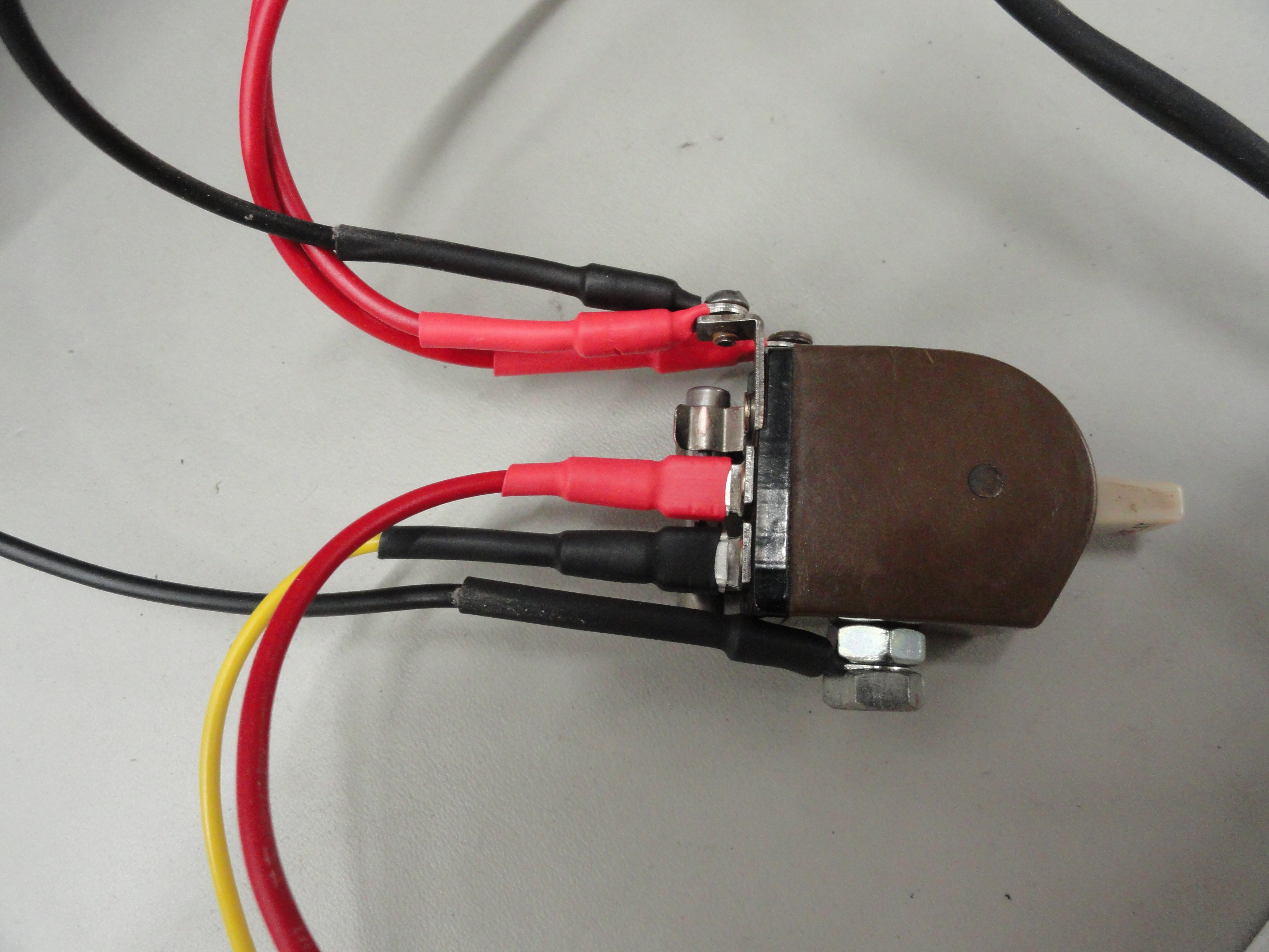
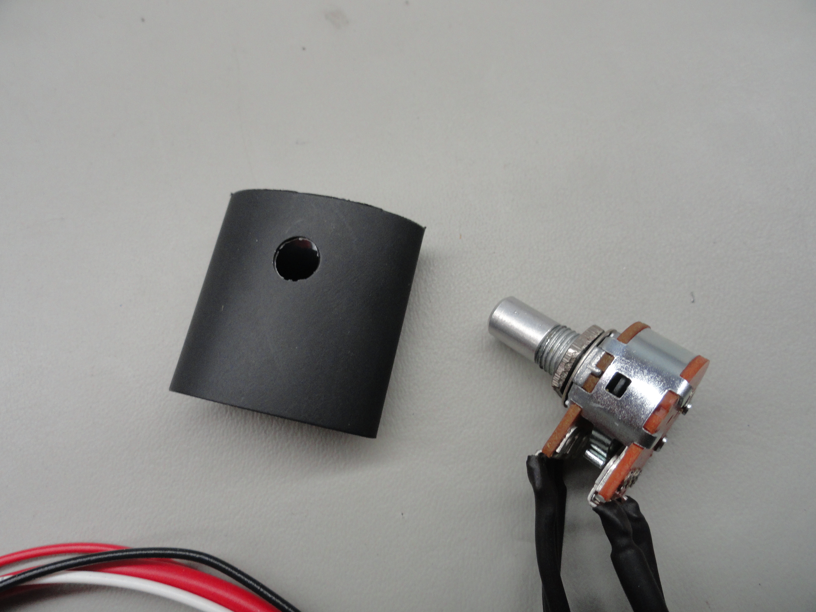
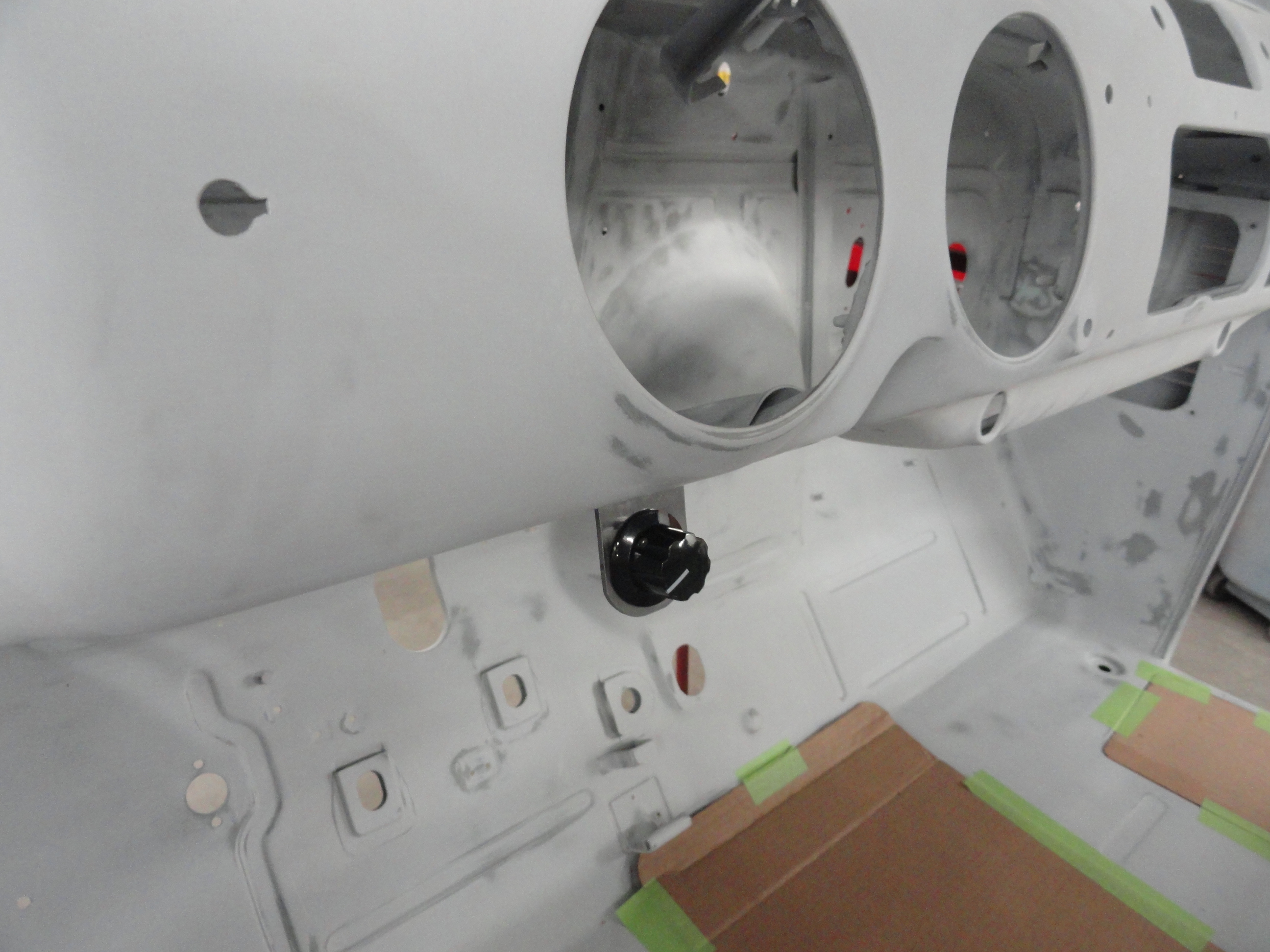
The Switch - There is modification to the original switch. If you think of a way to avoid this, let me know, but we need to remove the old 6 volt rated resistor. Most of you probably have bad ones anyway. To proceed with the modification, first decide which model switch you have. One of them has terminal brackets sticking up as shown, but the other style does not. If you have the one with the metal bracketry, cut the leads for the resistor at the rivet. If you have the other one, cut the leads so you can solder a wire to the end of it leaving the resistor wires as long as possible. This way you 'could' put it back if you choose to. With the resistor out of the way, remove the rivets at the top part of each of the two L brackets that are pointing to the side of the switch. Get a crimp-on female spade terminal and try to put that on your two uprights. You can't because they are too thick. That is what you need to address next. With a Dremel tool or something, very carefully remove just enough meat for the spade terminal to fit nice and tight. Do not change the thickness of the metal, just the width. You are only doing this on the two side facing terminals. Clean the back of the switch really good and ensure the contacts are nice and tight. If you have the style that just has the resistor cut from the bottom, just add a short wire to each of the two terminals and put a terminal lug on the end of the wires. This way you can plug and unplug your switch from the harness. Use shrink tubing to keep things from inadvertent damage.
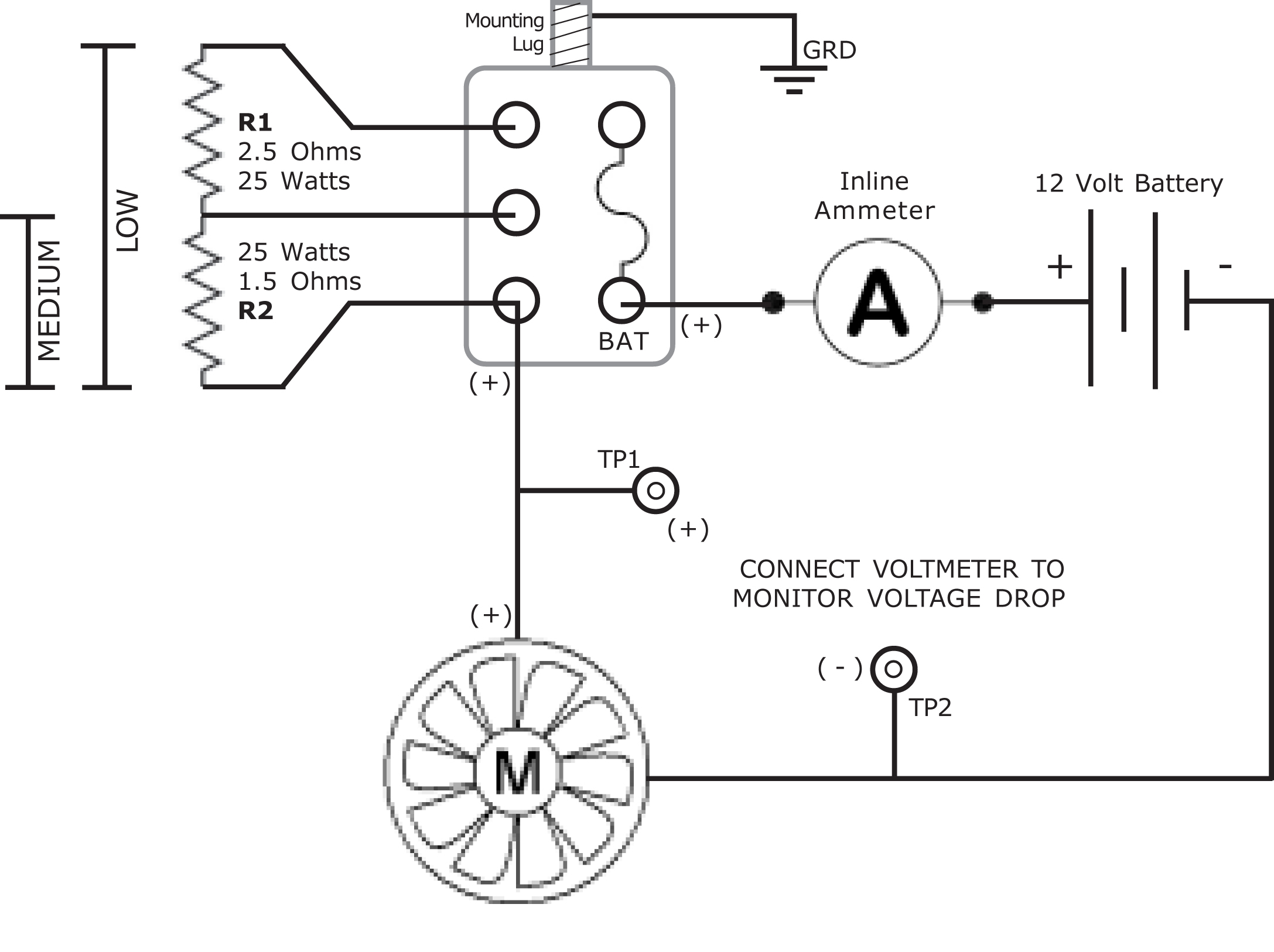
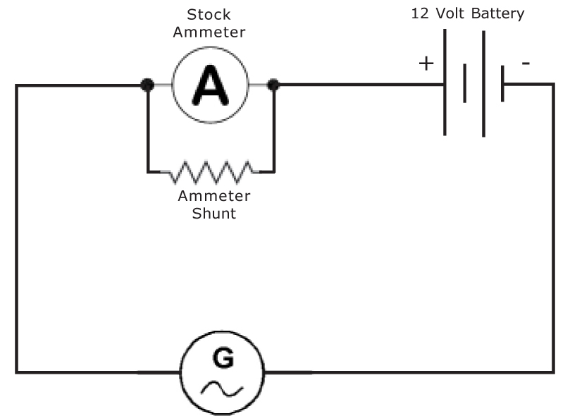
Making the Test Wiring Harness - We will use GM's original design for our circuit but deviate from it in relocating the resistors. Even though you see only one resistor on
the original switch, think of it as two separate resistors. In LOW, the entire length of the resistor is used. In MEDIUM only half of it is used. I made my test harness with
different colored wires so you can see where everything goes. The fuse holder screw terminal is BAT so that goes to the Battery. The other screw terminal will act as dual
purpose. One is to be the last contact in line for the 1.5 ohm resistor and finish the positive circuit to the Fan. The way this works is exactly like GM did it originally.
We are dealing with only the positive wire in all of this. The Negative wire from the fan goes directly to Heater Case thus the negative terminal on the Battery. This will change
a little when I describe the actual wiring harness, but for now we are testing so you get an idea of the proper configuration.
The Schematic - Here is what the test configuration circuit looks like electrically.
We will test using a well charged 12 volt car battery for the first trial then switch our test engine on for the second trial. This will give us a very accurate example of
what we will see in our vehicles. After some trial and error, I found the proper resistance values. Understand that a 12 volt fan motor and a 12 volt power source will
require substantially more power during the voltage reduction process. If you look at the stock switch, while it was convenient to put these resistors on the back of the
switch, that will no longer be feasible.
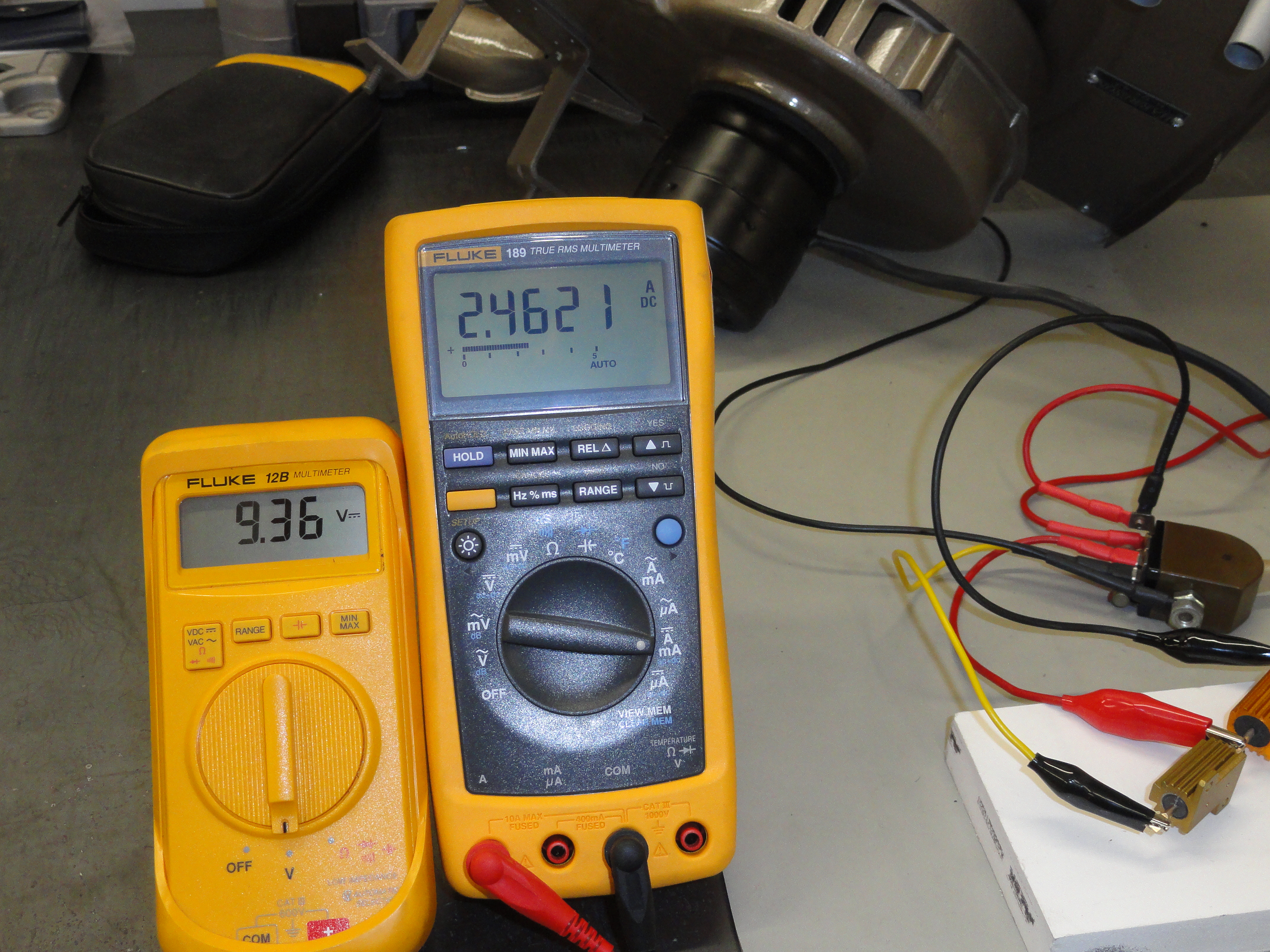
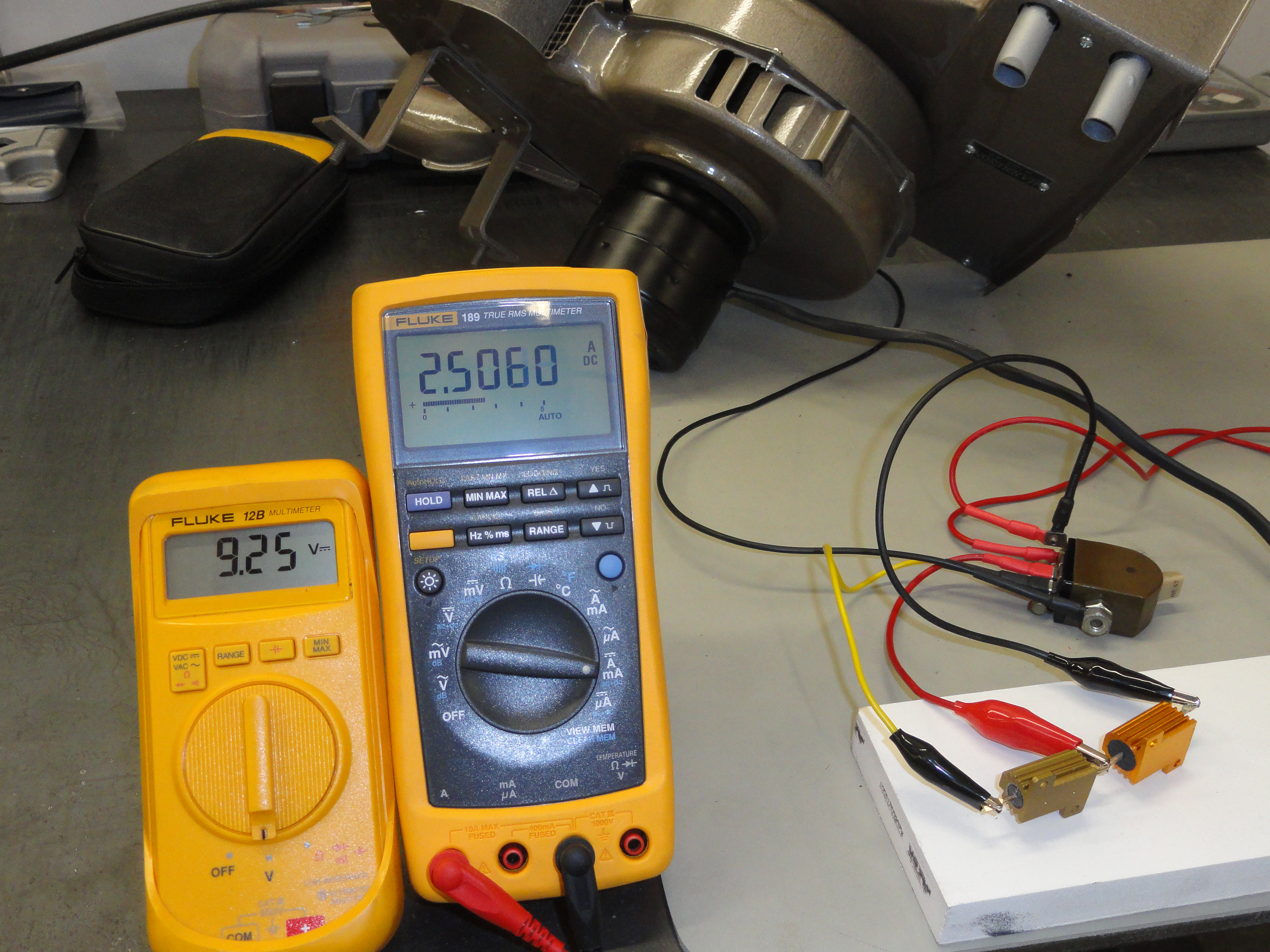
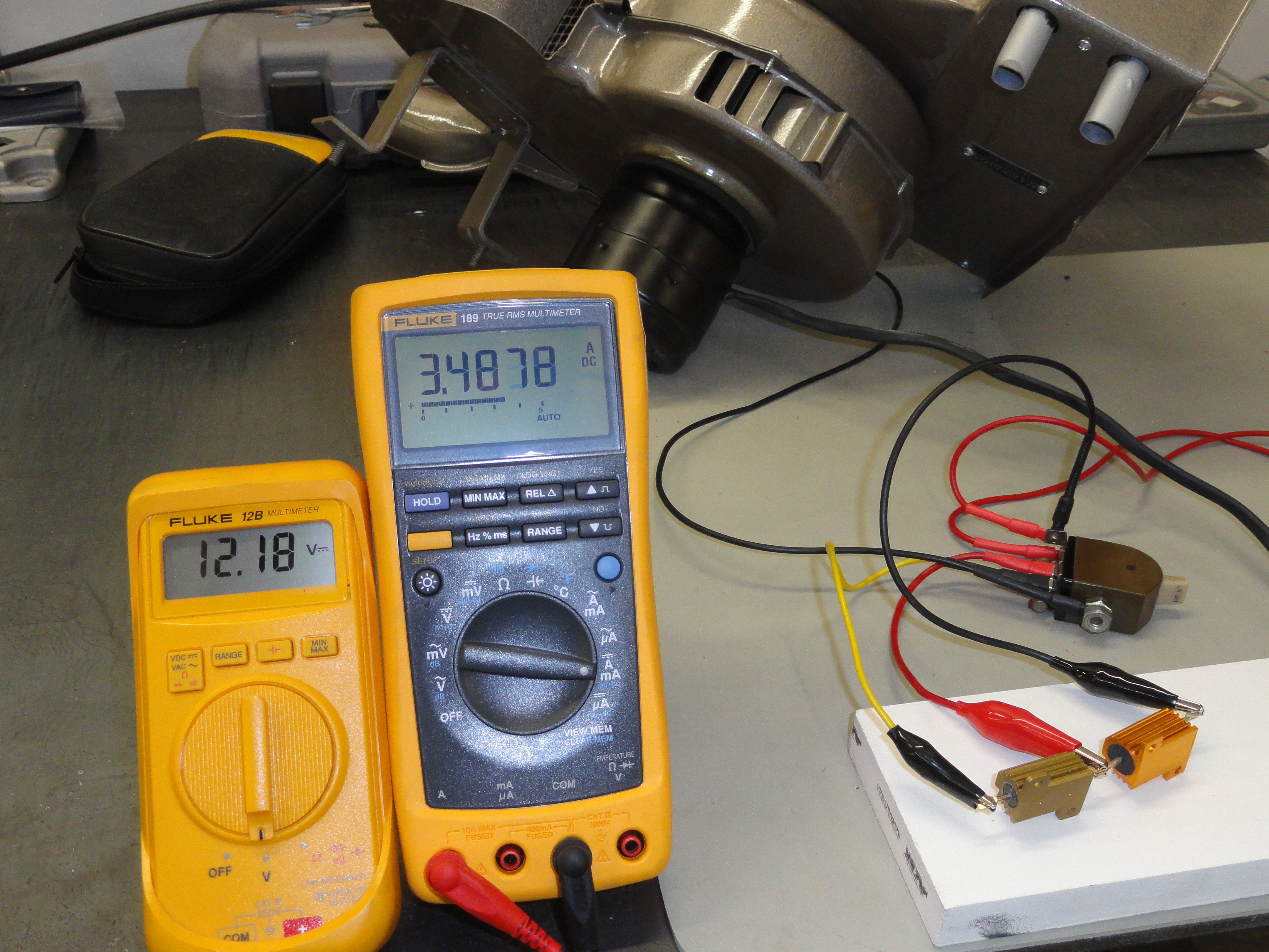
The Temperatures of the resistor array (after 15 minutes of continuous run time) are as follows:
These numbers are to be expected and reflect the proper wattage resistors. With these resistors mounted to a heat sink and in the air stream of the heater, they will last
forever. Pictures right are the numbers for our LOW and MEDIUM settings with our test engine with 42 amp Alternator running.

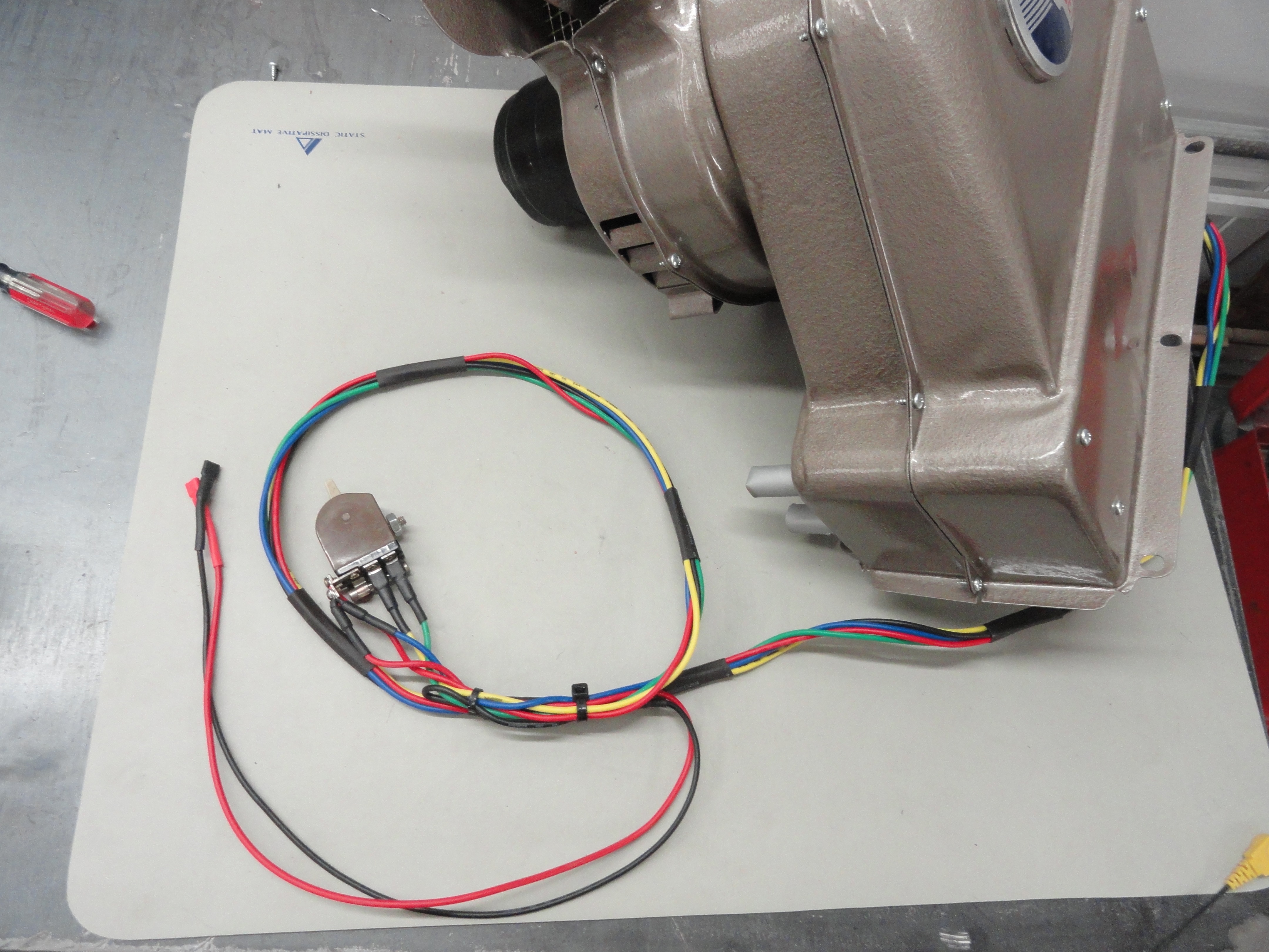
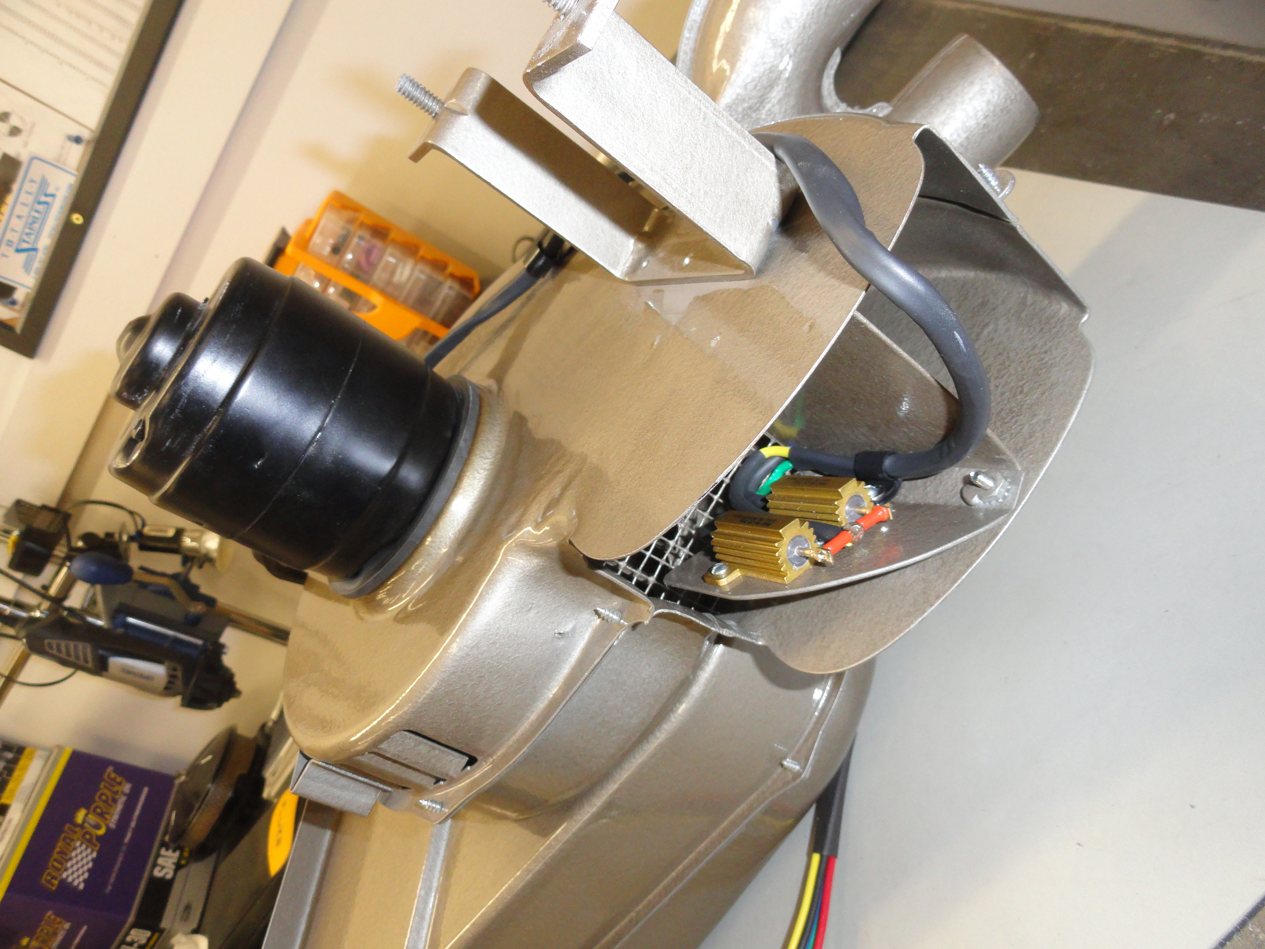
The Heat Sink and Harness Now that testing is complete we can address the exact location of the resistors and corresponding wire lengths. Upon examination of the Heater we are using, which is a 1947-1955 Deluxe Heater, a perfect place for a special bracket presented itself. I love it when a plan comes together that keeps everything looking perfectly stock with no evidence whatsoever that anything different was ever done. Now if you do not have this very same kind of heater, just do what I did and look for a suitable place that puts the resistors in the air stream. This was the best solution ever because it uses two existing screw locations and we will use the very same size head on our new screws to mount the plate. It will be impossible to see this modification from the outside without really looking for it!
Parts Listing

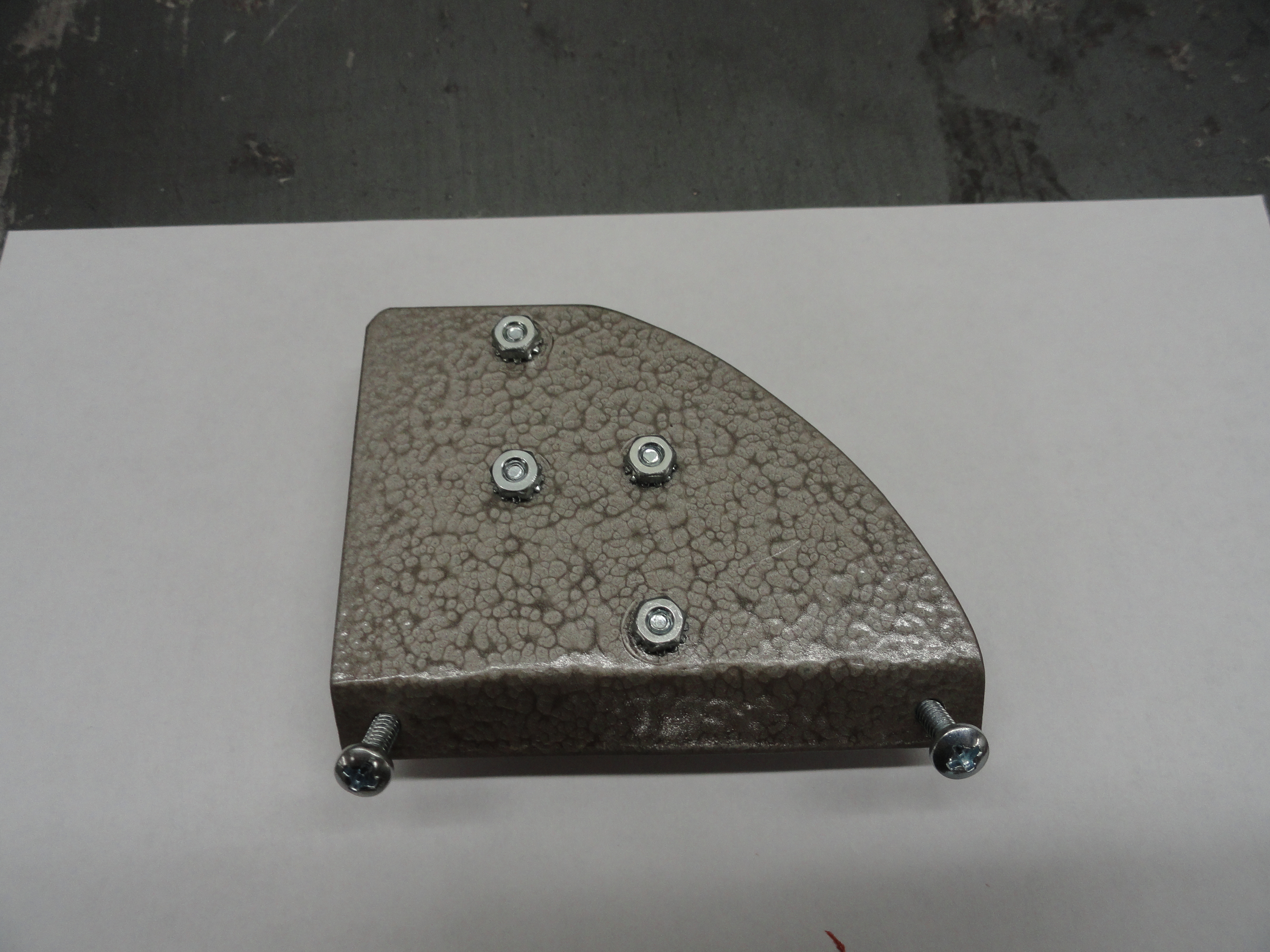
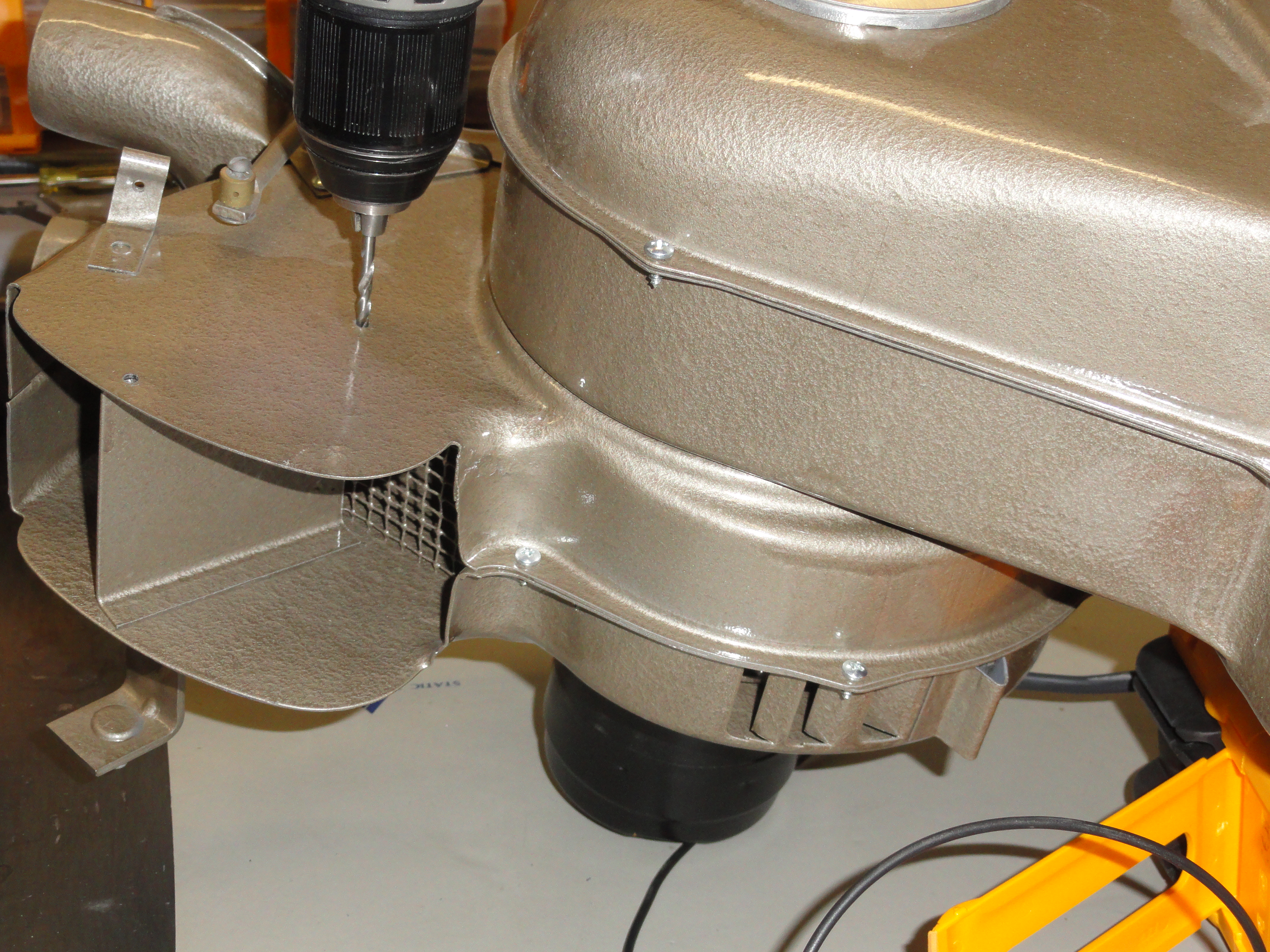
Proceed by using a 9/64" Drill Bit and drill out the two existing holes (shown above). This doesn't take much to do. We will be using 6-32 screws rather than the current sheet metal ones. The heads look the same and since the new plate has nuts welded to it, it makes for a very secure solution. The plate itself is cut out of a 2-1/2" by 3" piece of 14 gauge sheet metal. Make a line across the bottom (the 3 inch length) 3/8" from the bottom. This is your bend line. Put the piece in a vise so you can bend the rest of it to a 45 degree angle. To get that curve, you can place this plate up against the heater where it will be placed, or trace a large coffee can to get the proper curve. With the two screws removed from the heater, place the bent plate exactly where it will go and with a fine point Sharpie, mark the two mounting holes. Use a locator punch for best accuracy, then drill the holes out to the same 9/64" you used earlier. To make sure these nuts do not drive you crazy trying to get to them, I decided to weld them to the bracket. Just use two 6-32 screws and nuts with the nut on the inside of the bend. With your welder on a pretty low setting, carefully weld them to the plate. To locate the resistor mounting holes, place the two resistors as shown so you can use that fine point Sharpie and punch again. These are 4-40 Screws and Nuts so the holes need to be drilled to 1/8".
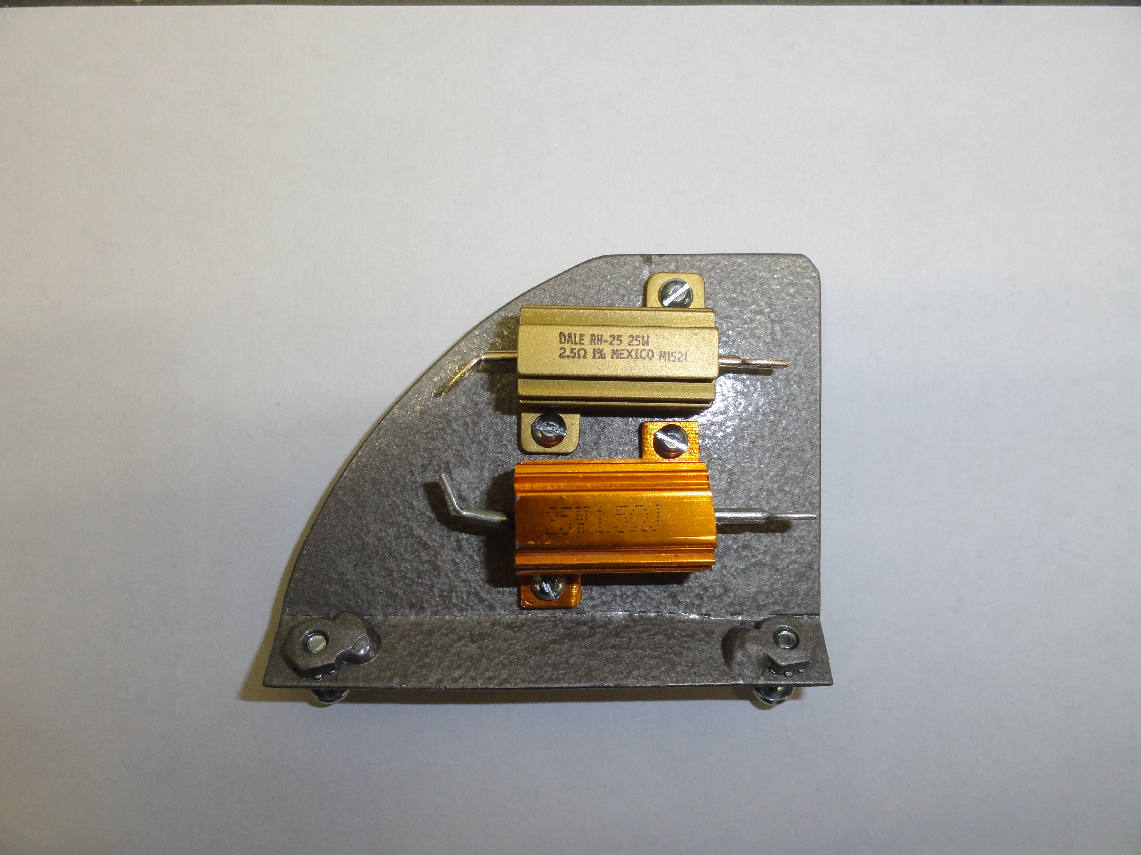

The entire plate goes inside the heater where it is not seen and yet keeps the power resistors cool. And yes, even with heat coming out of this air stream, the resistors will be cooler than if they were just hidden under the dash somewhere. Now we can proceed to create a wiring harness that will put these resistors in the circuit.
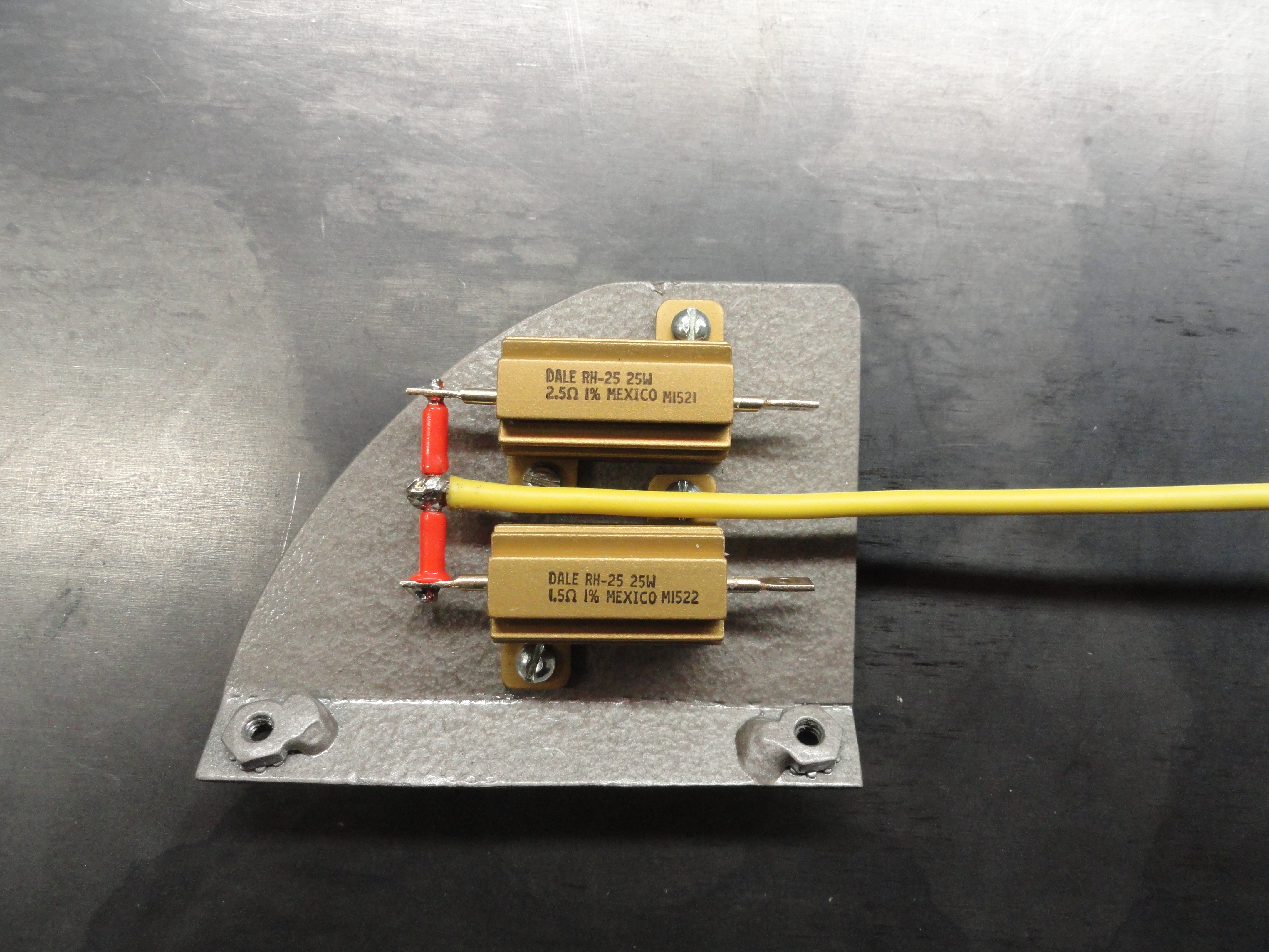
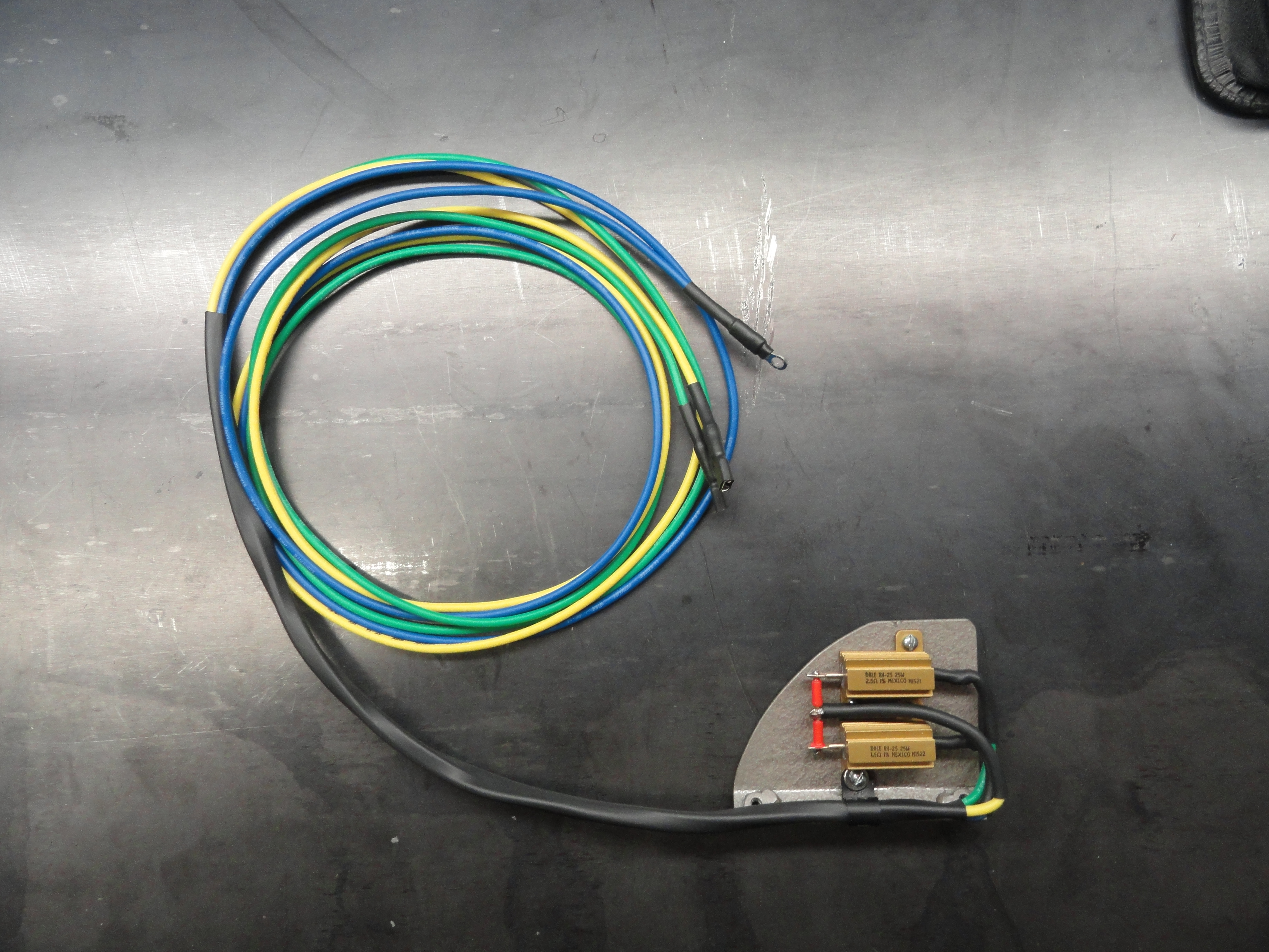
Start by creating a bridge across the two resistors as shown. We need to tap into the center of the resistor array for creating a low and medium circuit. Cut a piece of 14 gauge wire 7 feet three inches long and solder one end to your bridge. Cut two more pieces (preferably different colors) of 14 gauge wire 7 feet long and solder them to the ends of the resistors as shown. This gives us 4 ohms across the two outside wires and 1.5 ohms or 2.5 ohms across the yellow to each other wire. The 7 foot number may seem excessive. Do not cut it shorter. I actually tested this in the truck and it is necessary for neatly routing the wires for them to be that long. Cut a piece of 1/4" Heat Shrink Tubing 12" long and bend the wires as shown. Use a 1/4" plastic clamp to hold the wires in place. Keep the wires away from the two nuts that will hold down the heat sink so as not to poke into one of them by mistake.

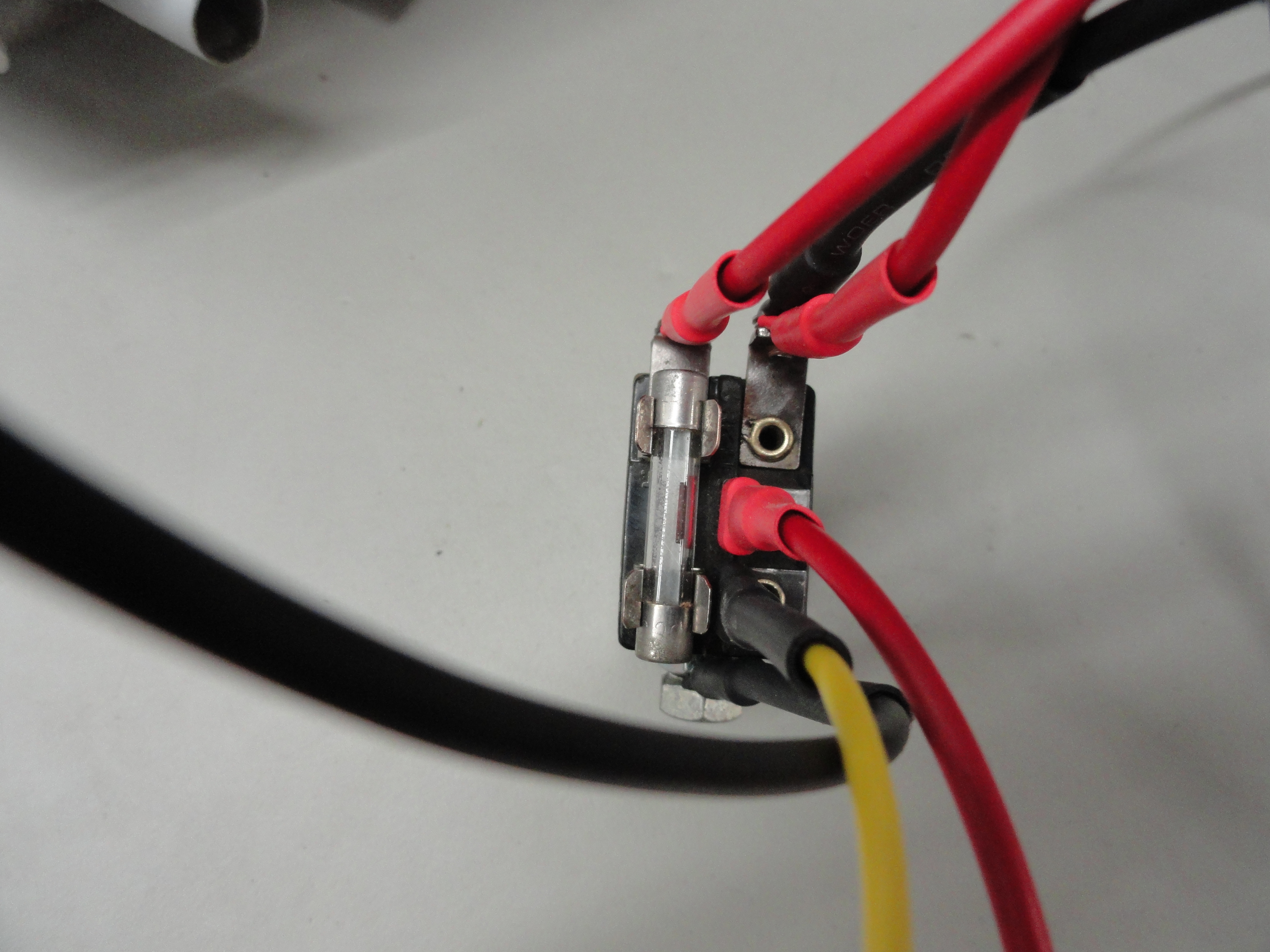
The yellow wire is our center tap so it needs a 1/4" spade terminal lug on it. This goes to the center of the switch or the spade terminal that is furthest inside. On the end of the wire that connects the 1.5 ohm resistor put a round lug terminal for putting under the screw directly below the spade terminal array. On the end of the wire that connects the 2.5 ohm resistor, put a 1/4" spade terminal lug and connect it to the outside spade terminal. The positive wire from the fan motor needs to be 7 feet in length and goes to the screw terminal on the switch below the terminal array. The Black or negative wire out of the fan motor needs to be long enough to reach a good ground. I plan on using a terminal box under the dash that I will put all of the grounds to, but really any non-painted surface will probably work. I made the fan motor negative about 8 feet 6 inches so it can go to the terminal array under the dash. Cut a piece of 14 gauge Red wire 18 inches long and put screw type terminal lugs on each end. Attach one end to the screw that is directly under the fuse on the switch. Ensure you have a good 14 amp fuse in the slot. The other end is connected to switched power.

Routing the wires cleanly is a matter of using those plastic clamps every so often. You want to wire it so that all 5 wires come out the top of the heater just above the bottom surface of the dash. Once the wiring is secure around the fan, simply lay the bundle in the lower part of the dash and run it across to the heater switch. The heater switch is normally in the second hole from the right just to the left of the steering column. Once you are there, run the two longer red and black wires to the appropriate terminal for switched power and ground. Most importantly, email deve@speedprint.com if you have questions!
This modification works flawlessly and was tested running the heater on low for 4 hours. The temperature of the resistors is hot to the touch, about 170 degrees in the air stream and they are in no danger whatsoever of failing due to heat. Although we encourage you to build it yourself, if you would like to purchase the heat sink with resistors, or the entire wire bundle complete with clamps, select your choice here:
We can't conclude this section of the article without mentioning The Solid State DC Motor Controller. We tested one with both 6 Volt Fan Motor and 12 Volt Fan Motors
and it is a very nice way to control the Heater Fan. Special thanks to Wayne for this idea! Let's examine the Pro's and Con's first.
Pro's
Con's
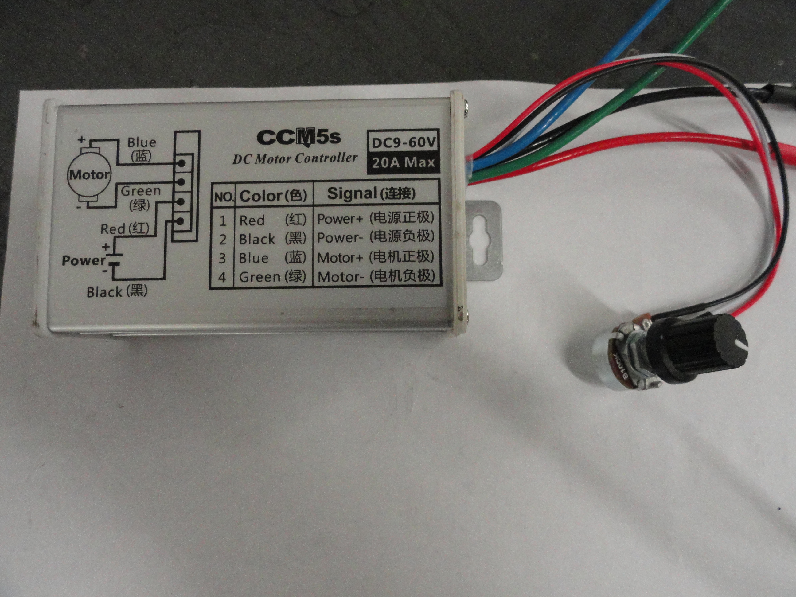
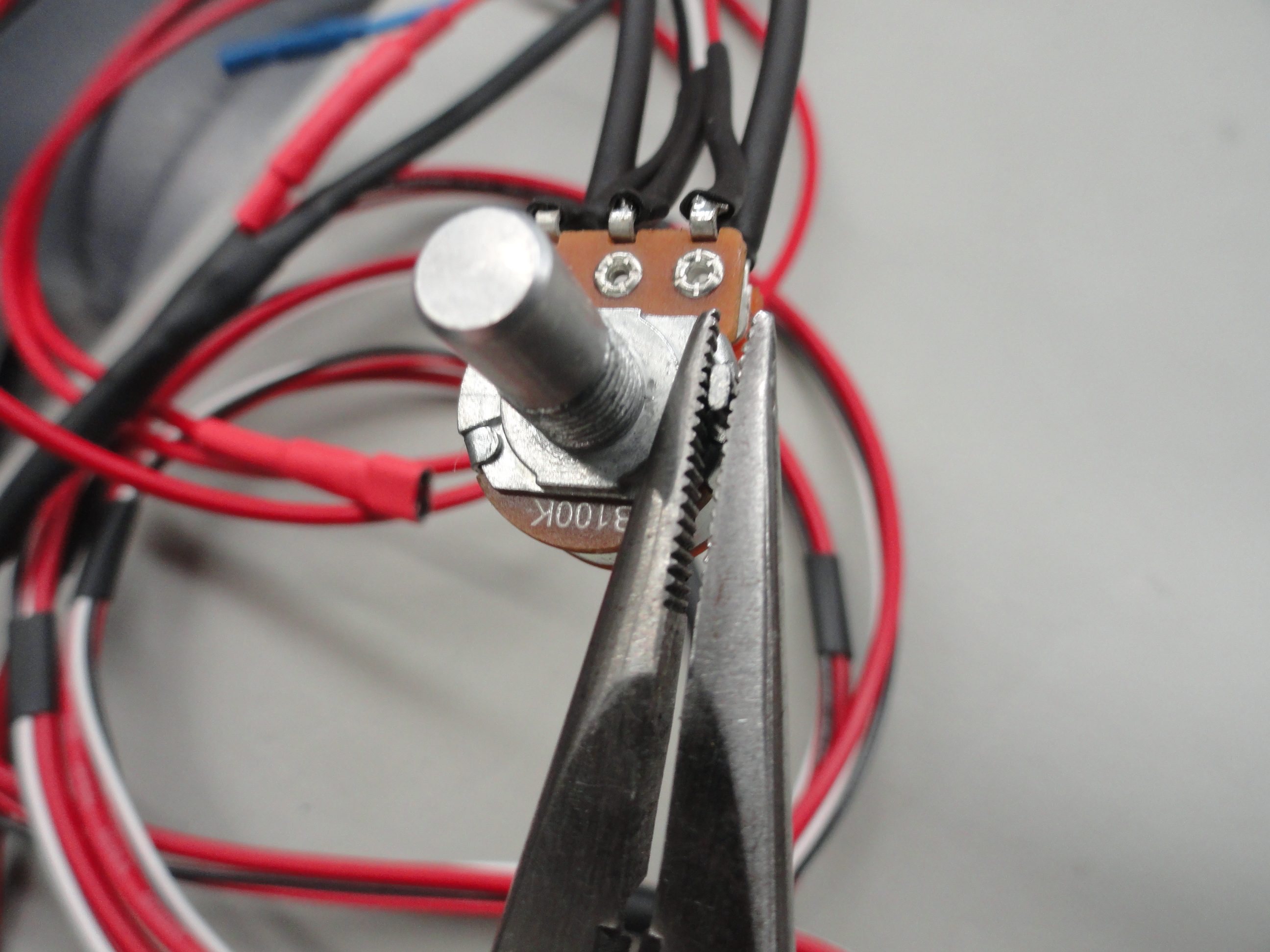
The instructions on the unit are very straightforward if you have a 12 volt motor. For you 6 volt motor fans, put the reducer in between the controller and the motor in the Positive line. Other than that, you just hook it up and it works. Let's start with the 12 volt motor in explaining the details. To install this controller in your truck, the best place for it would be mounted to the Heater Assembly out of sight. That would place the controller nearest the motor. Then there is the issue of the switch. If the plan is to use a Stock 1947-1955 Toggle style with three settings plus OFF, then you will need to modify your switch. The disadvantage to using your stock switch is you will only get three settings, Low, Medium and High. If you can find a Rotary switch style you can live with, you can adapt a Potentiometer to fit and then you get infinite RPM control.
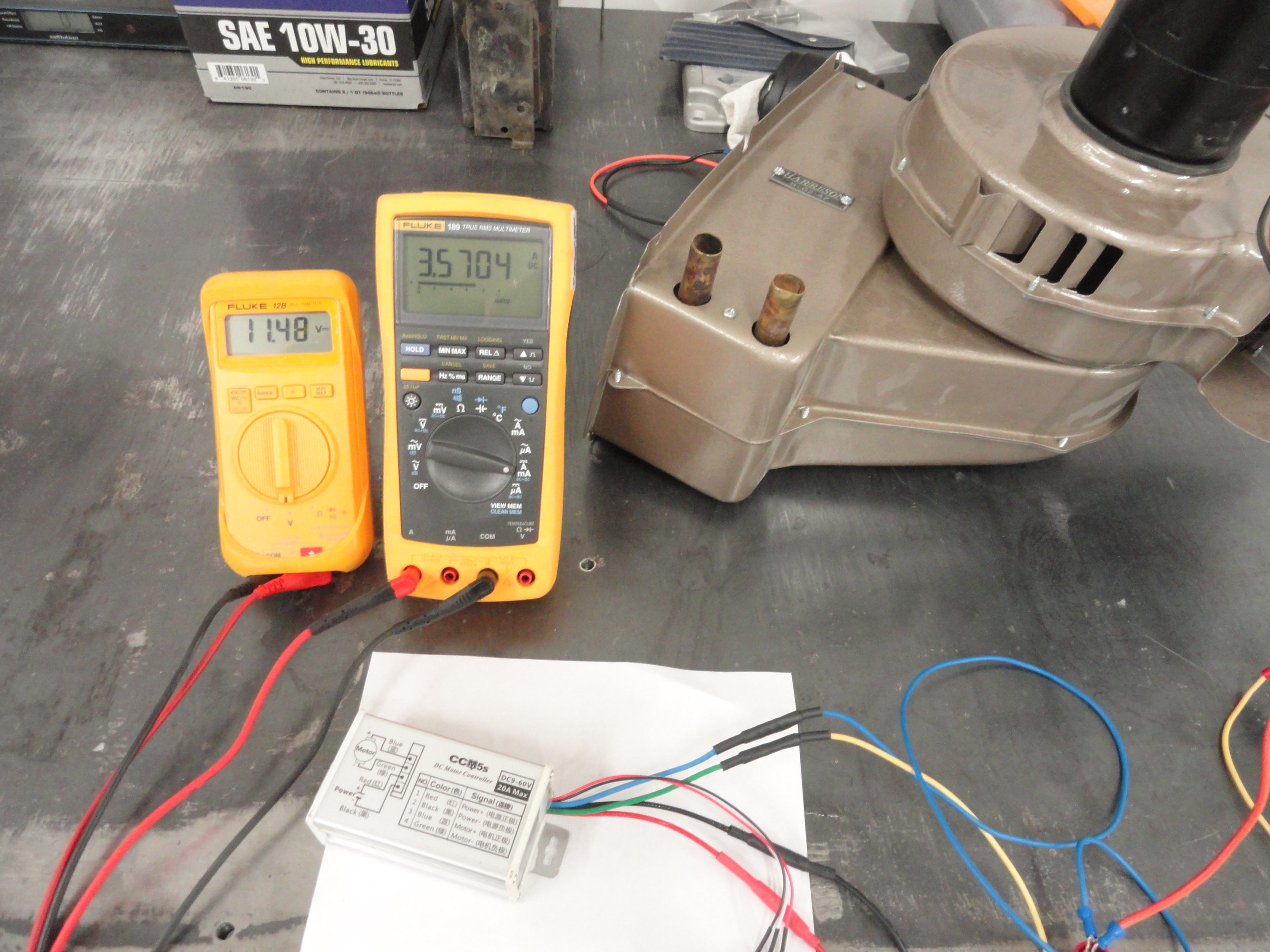
To aid you in determining how to proceed, I am including some pictures and explanations of each. The pic on the left is a 12 volt fan motor running at 12 volts using the Controller. The Potentiometer (Dial Adjuster) is at Maximum Ohm Value of 100K ohms. You care because the resistance value is how this Controller controls the motor. 100K ohms means Maximum RPM, Maximum Voltage and Maximum Amperage. By controlling the Resistance (Ohm value) we can control the motor speed.
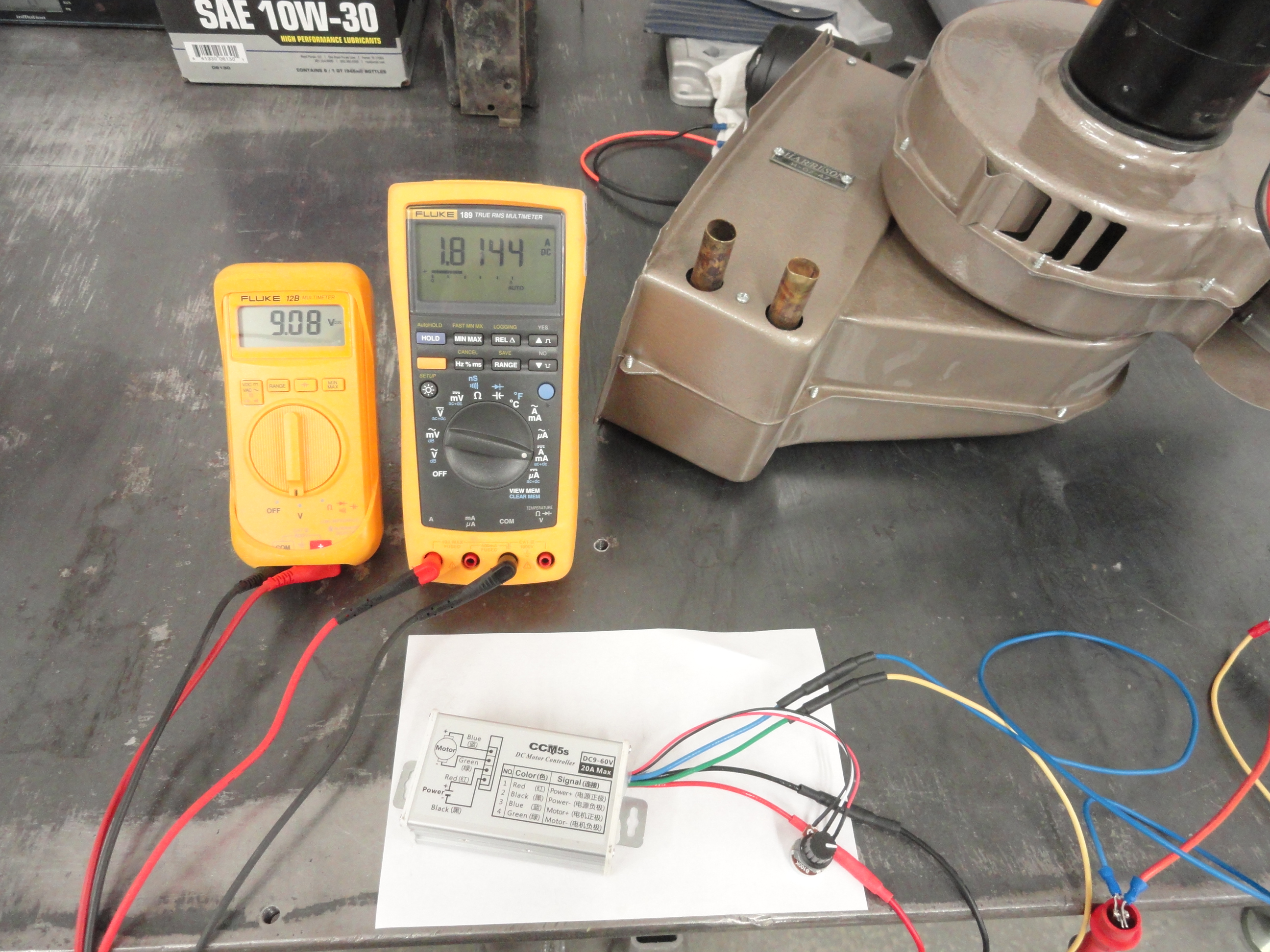

Here we have 9 Volts on the Left, and 6 Volts on the Right with their associated Amperage values. These numbers represent Medium (9v and about 2450 RPM)) and Low
(6v and about 1500 RPM) RPM. What is not shown is the work I did to determine the Ohm Value at each of those two settings, which is merely taking power off the
motor long enough to ohm out the Potentiometer at those two settings. This is how we determine which resistance value we need for your Stock Toggle switch. If you
hook it up without changing the resistors, it will not run at all because the resistors are of such low (.8 ohms) ohm value (in Low and Medium).
Ohm Value Needed for Medium: 55K ohms (1 Watt)
Ohm Value Needed for Low: 35K ohms (1 Watt)
As you can see 55,000 ohms as opposed to .8 of an ohm, the resistors must be changed on the back of your stock switch. This is because the Potentiometer is
controlling solid state components inside of the box. Remember that your Stock switch will only give you three fan settings. Using the stock switch I would
recommend going with the resistor array explained in the previous section. Less wires and ZERO solid state parts to go bad, not to mention NO resistors on your
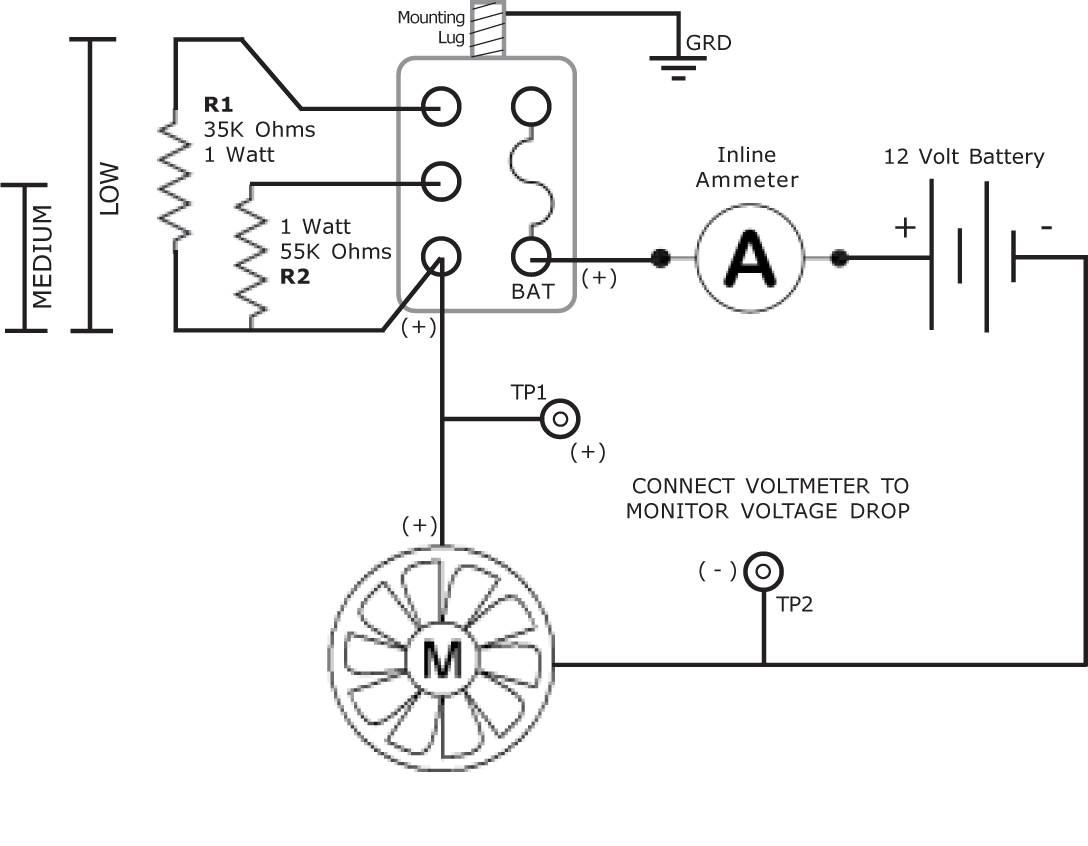
switch at all. Below is the bench test diagram that will show how this works.
To my way of thinking, since the Stock switch is pretty rare because it was a dealer installed item or even an aftermarket one, for this particular Fan Control
system, I would go with a Rotary Switch solution. This would allow you to put a larger (physical size) Potentiometer together with an aftermarket knob and bracket
and give you the full benefit of having such a powerful Motor Controller. Let's examine how to do this. We need:
Parts List:
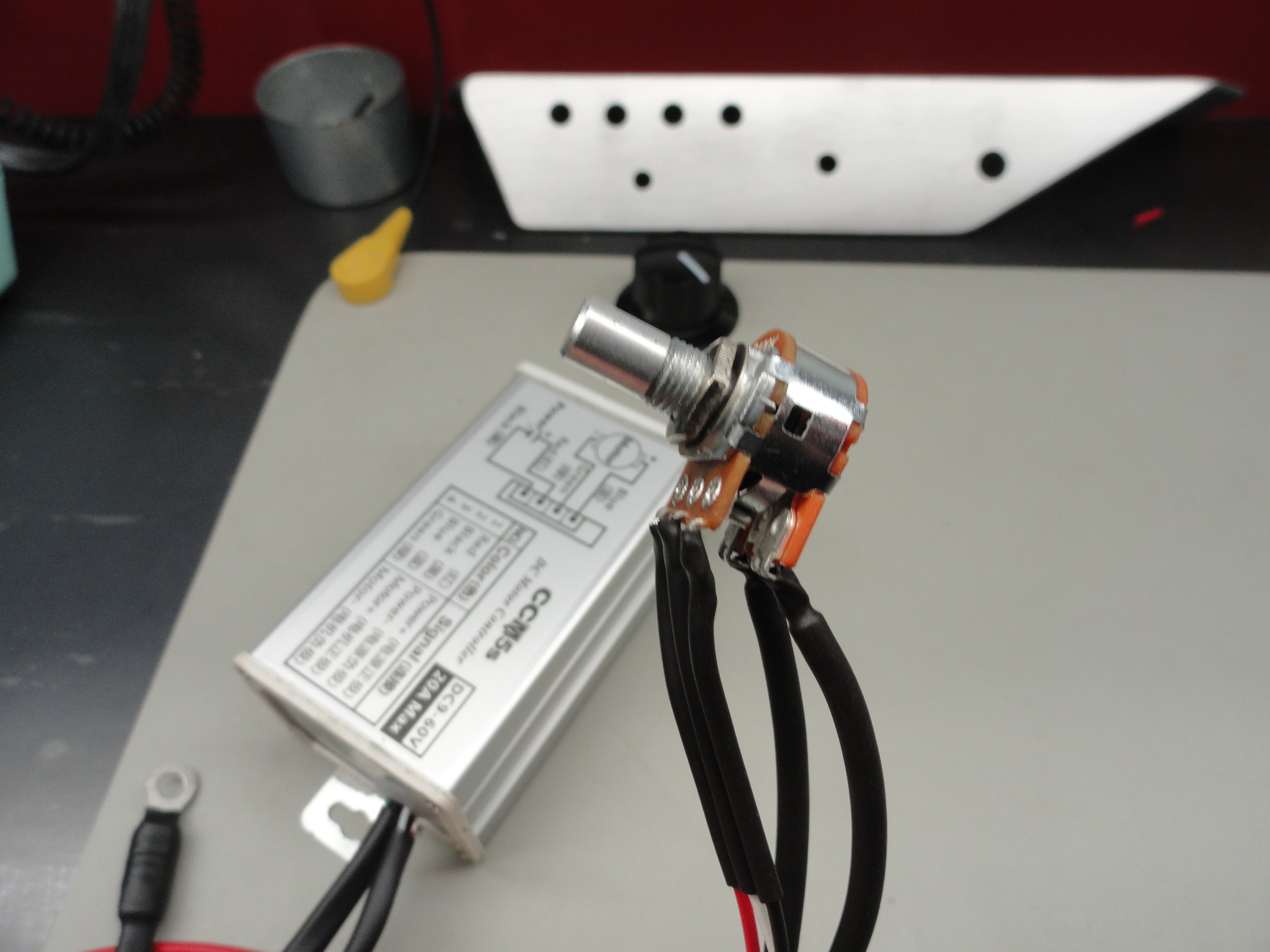
The Potentiometer in the link above is better than the original one that comes with the DC Controller because it has an OFF De-tent. This keeps ALL power off the motor when it's not in use. The one that comes with it keeps residual low power on it all the time. The mounting bracket is discussed below.
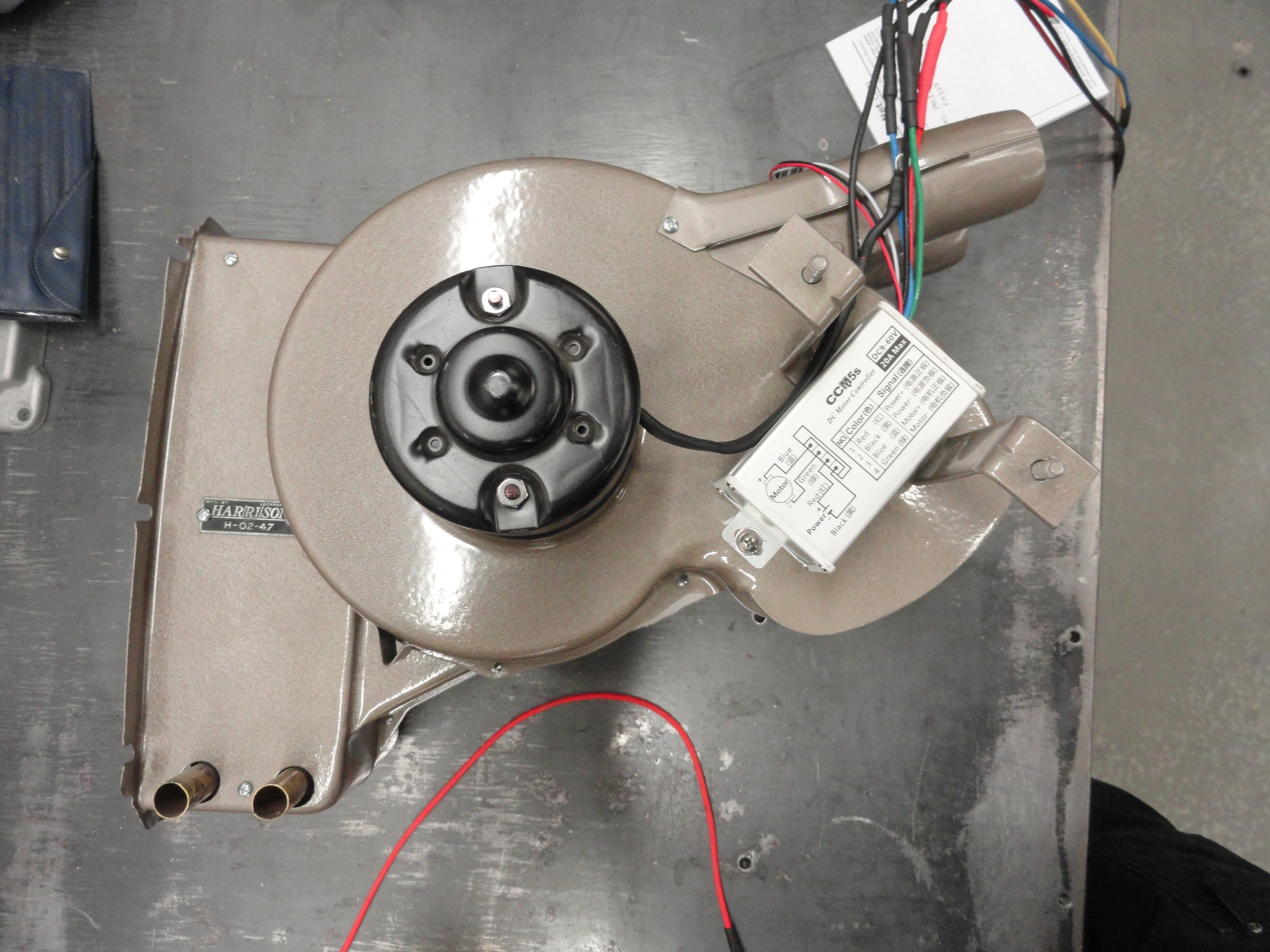
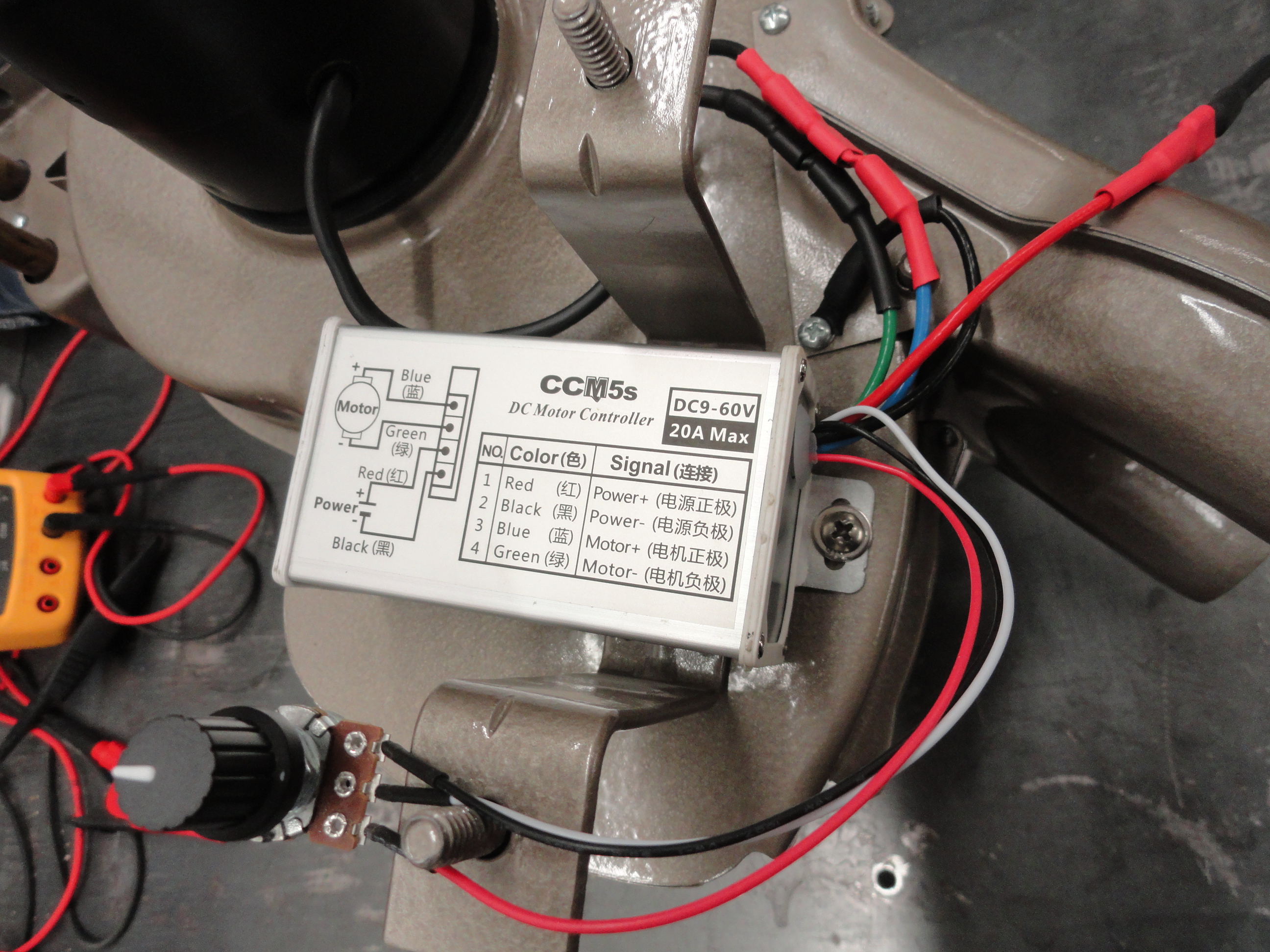
Wiring the rotary switch and DC Motor Controller isn't difficult but it's way easier out of the truck and on the bench. I mounted the Motor Controller on the back of the Heater Assembly near the motor. This puts it where it belongs (near the motor) and keeps the power wires shorter. The original Positive power wire from the Ignition Switch to the Fan Motor would go to the Red wire on the Controller instead, the Negative wire on the Fan Motor is wired to Green on the Controller. The Black wire on the Controller is grounded to the case. The Positive wire (Blue) to the Motor would connect to the Positive wire on the motor. The three wires going to the Potentiometer have to be lengthened and sent across the inside dash to the switch. In other words, exactly like it is currently wired and using the chart on the top of the Controller. If these instructions are not clear enough, just email deve@speedprint.com and I will explain it for you better.
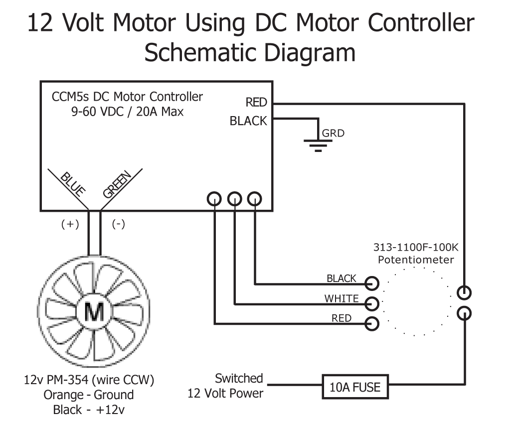
To use our suggested Potentiometer instead of the one that comes with it, we need to extend a fourth wire, the RED power wire from the Controller. That 16 gauge wire needs to be the same length as the three 22 gauge wires going to the Potentiometer. This is because the new Potentiometer is equipped with a Switch. Fully CCW is the OFF portion of the system and completely disconnects power from the Fan and Controller. To do this, we must run the Controllers power wire to the 2 Pole Switch portion of the Potentiometer. The rest of the Potentiometer is wired the very same as the Potentiometer that came with the Controller. If you are inclined to wire the Green (-) wire to ground, resist the temptation. This will not work. The motors wiring, both positive and negative need to go to the Controller. Here is the Schematic Diagram for a 12 Volt Motor.
I am a big fan of a few important intricacies when putting all this together. One is tinning the wire ends with solder before crimping on the terminal ends. This makes the terminal ends noticeably stronger. Then, finishing up with heat shrink tubing of various sizes to give it the finished look and most of all, to protect the wiring. The Potentiometer needs the small tab broken off that acts as a placement guide, but that snaps right off, then I use a 1 inch long piece of 3/4" marine grade shrink tubing with a 1/4" hole punched out of it for the knob end to wrap the entire potentiometer in shrink.
The location (mounted to the heater assembly) is really nice because it is where the controller really belongs. To wire it nicely keeping in mind easier replacement in case of a malfunction, I used spade terminal disconnects. Place the Controller in the correct location as shown, then mark the holes for drilling. Use a 7/64" drill bit and #8 sheet metal screws. I used two #8 washers as well. It's very solid and if I had to get in there to remove the Controller, a stubby Phillips would do the job. An additional reason for putting the Controller on-board the heater is so that we only have to run one power wire (to wherever the heater is powered now) and then three 24 gauge wires for the Potentiometer across the bottom of the dash. This is a really nice solution! No heat is generated whatsoever and we have infinite control of the fan motor's RPM.
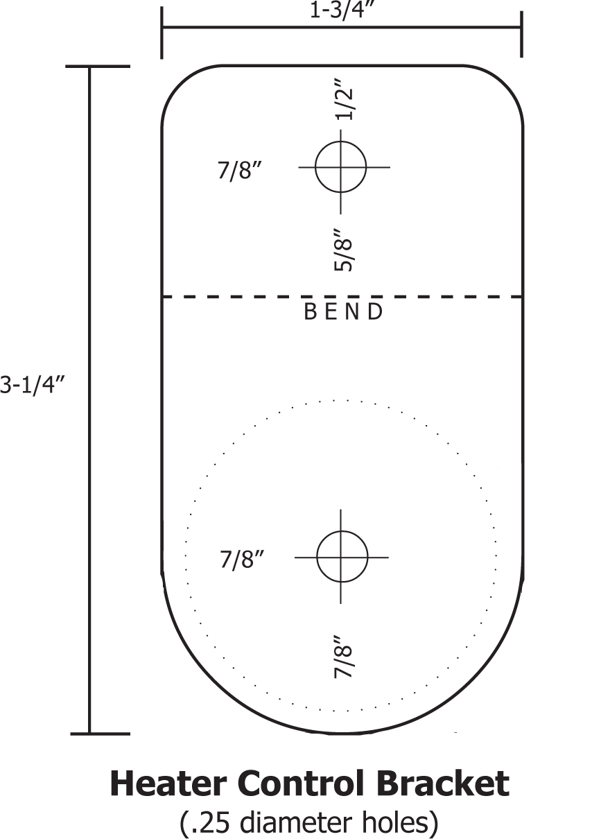
Now there is the consideration of what to do about the switch. Going with this amazing DC Motor Controller requires you to go to a rotary style switch. Where do we put it? How do we mount it? It is not all that hard to fix this problem by making a relatively easy Heater Control Bracket for under your dash. The design I am proposing here will look nicer and be stronger than those aftermarket rotary clamp-on ones. This bracket uses the very same hole that the original Heater Switch occupies. It uses 12 gauge Stainless Steel and takes very little time to make. Then, use an Ohmite 5150 Knob on the Potentiometer in the Parts List. This knob is 1-1/2" in diameter, is solid thus heavy and really feels solid in its operation. If you go with the Warning System described HERE, the bracket that comes with the Warning System already has this feature already built in.
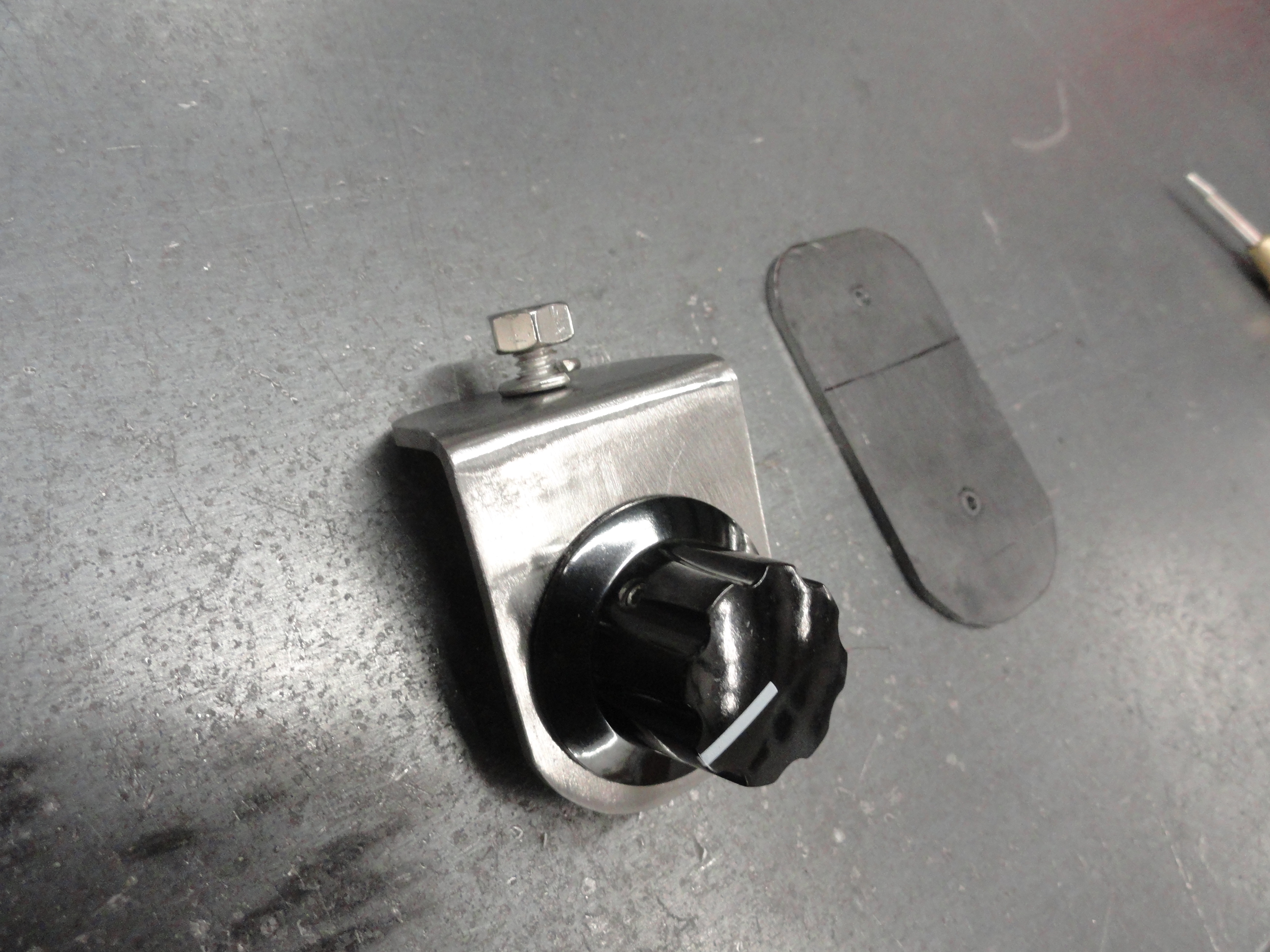
To make this bracket, I used 12 gauge stainless steel, 1-3/4 inches wide by 3-1/4" long. The bend is at 1-1/8" from the top. The bracket is designed to go into one of two stock hole locations under the left side of the dash. These were put there originally for the heater switch anyway if you have a 47-55 1st Chevy Truck. The top hole is drilled using a Number 7 drill bit and then tapped to 1/4-20. The bottom hole is 9/32" which is two fractional sizes bigger than 1/4" for the Potentiometer. A stainless 1/4"-20 bolt is then threaded through the hole for anchoring to the underside of the dash. The potentiometer is bolted in place, then the Ohmite 5150 knob has two set screws to hold it on the potentiometer. The only choice you have to then make is what color to paint it. Since it is stainless steel, you have choices. You can either polish it up nicely and leave it bare, or rough it up and primer then paint it.
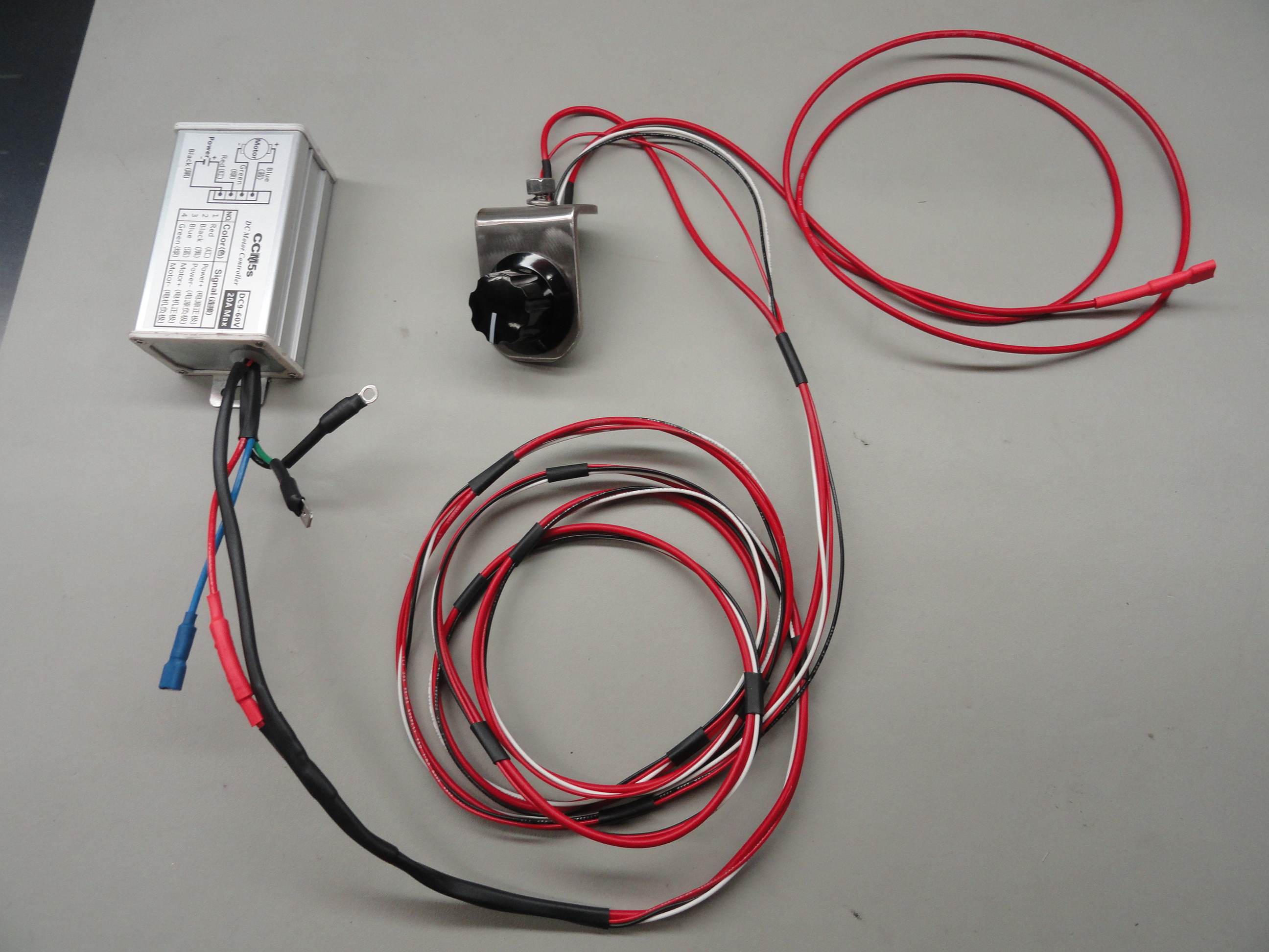
"Complete Controller Solution" comes with the entire wiring bundle, Controller, Switch Bracket with Potentiometer and Knob ready to install.
"Stainless Steel Dash Bracket" is the bracket with the 1/4" stud, nut and washer for installing under your dash.
"Stainless Dash Bracket with Potentiometer and Knob" is self explanatory. Knob is high quality 1-1/2" Knob with Deluxe Switched Potentiometer.
To install the Kit we send you, find a location very near the Heater to locate the DC Motor Controller. The very best place to put it requires removing the heater and bolting it
directly to the heater housing as described earlier in this document, however, you can mount it to the Passenger Side kick panel near the top as well. The short black wire with
the round terminal needs to be grounded so bolt that to the controller mounting.
The other two wires are Blue for the Positive side of your existing motor and Green for the Negative side of your existing motor. Important! The way your current motor is
wired, negative just has a round lug on it that is grounded to the heater case. This is not acceptable and needs to be re-routed to the Green Wire on the controller.
Run the wire bundle of the 4 wires with the switch and bracket under the dash to the desired switch location. Once your switch is bolted up nicely, run the Red wire to a 10
amp fused power source. This can be the ignition switch so you have it on switched power. If you have questions on any part of this installation, this document will likely
provide you the answers, just scroll up! If not, email Deve@speedprint.com and I will gladly answer your questions.
Since you will not be using the rest of the wire that used to power your heater motor, trace it back and disconnect it from it's source, or use it per the instructions above.
There is a nice schematic diagram to help you above.
The Ammeter When changing over to 12 volts, it is very important to ensure the stock Amp Meter is sufficient to handle your new charging system. On our 1947-1955 Chevy Trucks, the Ammeter is a 50 Amp Meter. If the new charging system does not exceed that, chances are you are good without doing anything. I highly recommend during this process that you check your wiring for serviceability. If you find your charging system wires in good shape and you have less than a 50 amp Generator or Alternator, you are good to move on to the next step.
The Schematic - Here is what the Ammeter circuit looks like electrically including a Shunt. Your 1947-1955 Chevy Truck is not equipped with a Shunt. This means
that 100% of the current that is created by the Alternator goes directly through your Ammeter. There is no alternate path. Since the gauge is rated to a maximum current carrying
capacity of 50 amps, and the 8 gauge wire that is used to connect the main charging system is rated for 75 Amps (on a good day and does not include the condition of 65 year old wiring),
we need to examine this issue further.
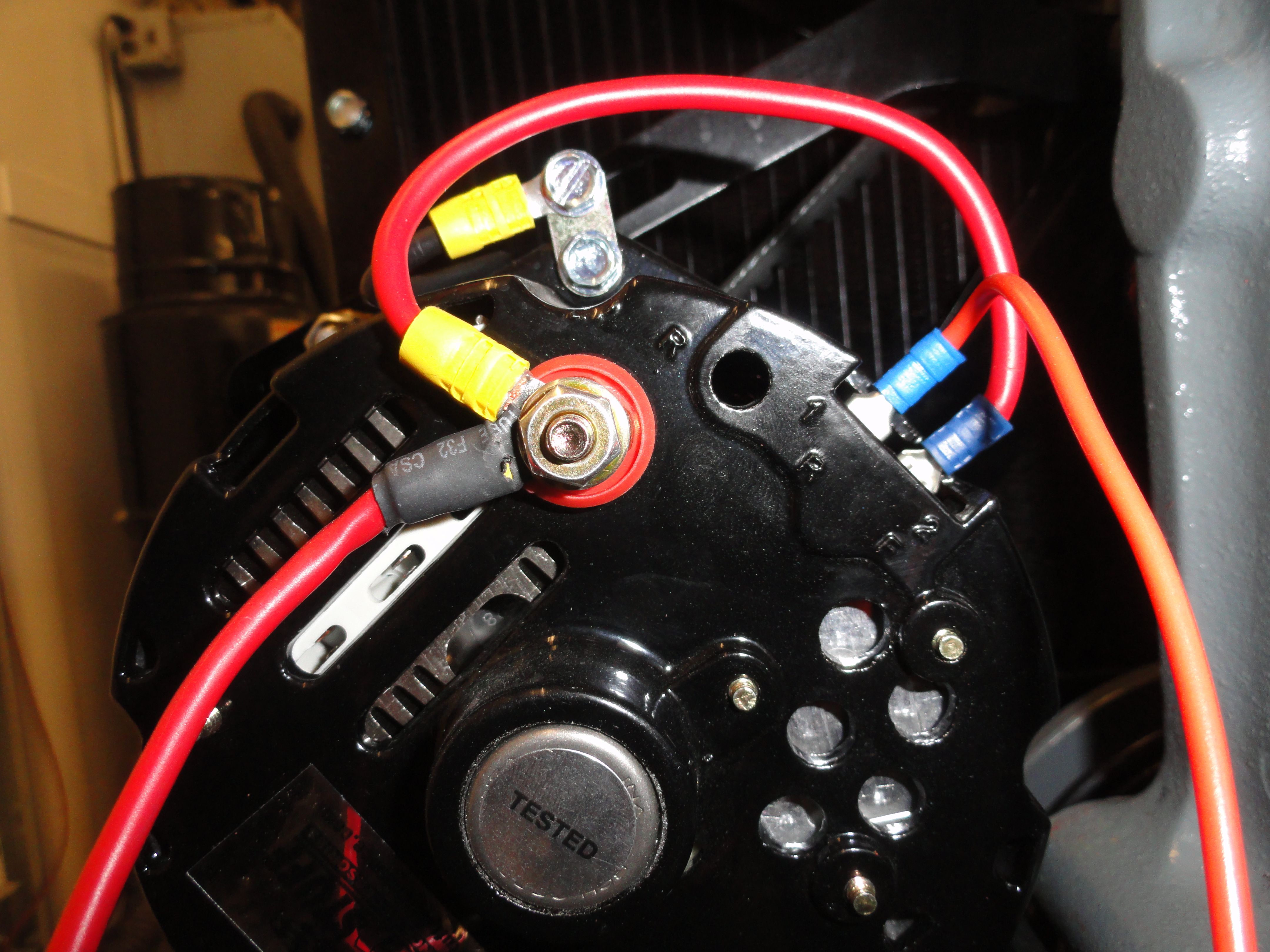
If you decided due to the inexpensive One Wire Alternators that are out there, to eliminate your Voltage/Current Regulator and Generator and upgrade to a more modern Alternator, you might be tempted to get a 60, 80, 100, even 150 Amp Alternator. The downside there is you MUST put an Ammeter Shunt in the circuit in order to enjoy the peace of mind and safety you are accustomed to. Purchasing more than a 40 amp Alternator is really wasted unless you are planning to use an AC Inverter or something that really hogs power. Since the meter is rated for 50 amps, anything above that requires a Shunt. A Shunt works by directing the excess current through an alternate path.
Shunts are VERY low resistance values in even lower than the milliohm range. In order for them to be balanced to the point where the correct amount of current goes through your gauge and the correct amount is deferred around the gauge, engineers have to mix certain conductive metals to get a hybrid metal that will conduct electricity with almost no resistance. Because of this, Shunts can be expensive, in about the $40 range or more. There is a lot of information on the Internet about this issue. Each shunt needs to be custom for the amount of current going through it. Without precise mathematics behind the decision, your Ammeter will not read properly. It is not practical to offer Shunts as a purchasable item because of the expense. This leaves you with lesser choices to give you the peace of mind you have been accustomed to all these years. Remember, you do not need a Shunt if you purchase less than a 50 amp charging system.
If you have a larger Alternator than 50 Amps, there are two ways to economically resolve this issue with Safety being Number One.
One to assure the safety of you and your vehicle is to put the Inline Fuse in the circuit. A Circuit Breaker is a thought, however, they are thermal devices and notoriously go bad after only a handful of resets. It is best to use a 50 Amp, 4 to 10 gauge rated inline fuse-holder and carry a few extra 50 amp fuses with you. Here is why the fuse is a good idea; According to the Electronic Engineers I have spoken with about this issue, the ONLY time the Alternator could charge at its maximum rate would be in the case of a dead short. This is the worst case scenario and it isn't pretty. A dead short on a 100 amp alternator would fry the wires, ammeter and likely start a fire. But, unless there is some catastrophic wiring issue, the Alternator will not charge above the rate the Battery can accept. This is well below the 50 amp ceiling. A dead short is a possibility so do not take this issue lightly. Not when all it takes to remove the worry is a $10 inline fuse!
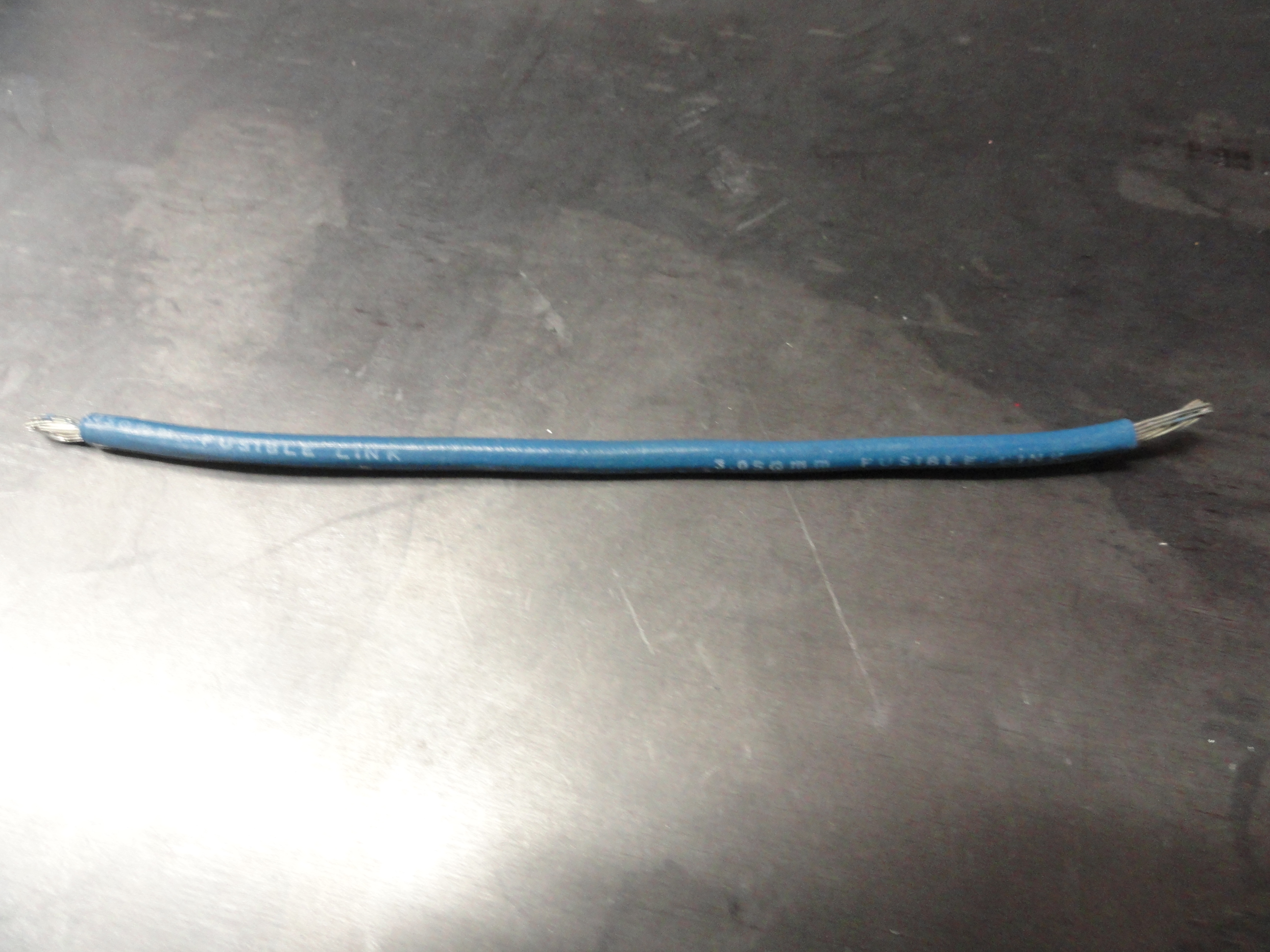
Another idea, and one that many Auto-Electric technicians prefer over the fuse is a Fusible Link. This short piece of wire-looking link will melt away during an over-current situation similar to how a fuse would. Splice this piece in at the Alternator same as you would a wire extension. Do not put it at the Battery because of the possibility of the heat igniting battery gases in the case of a dead short.
Equally as important as upgrading your charging system is inspecting your wiring. For the Charging system line which includes the wire going from the battery to the ammeter gauge to the Alternator, you should be using fresh 8 gauge wire. This is the thickest positive wire behind the dash. Good wiring is a necessity. Do not think just because you have 6 volt wiring in your vehicle (which carries twice the current thus beefier) you can get away without inspecting those 65 year old wires! Electrical system fires are not to be trifled with. They can burn down your vehicle and worse.
The other thing that makes sense is to change the Ammeter to a Voltmeter. This is how all new cars come from the factory nowadays. They all have Voltmeters. This is so that we don't have 50 amps of current flowing under your dash. This was done at about the same time as high Amperage Alternators came out. It is of course arguable the benefit of not having a measure of Charging Current rather a measure of how many Volts your battery is charged to. But here is my argument FOR making this change... Alternators these days come with a terminal that is used for a charging system indicator light that lights when the charging system is not charging the battery. So, you have everything you need to see if your Alternator is putting out the necessary current, and then you have a NEW indication that tells you the health of the battery, the Voltmeter. One of the things on my To-Do list is to take the original Ammeter apart and see how we could modify that Meter to read Volts rather than Amps. Since both are based on the D'Arsonval Meter Movement, I wonder why we cannot modify the gauges. Anyone with more information, please share!
If you have been paying attention to this light reading, you are wondering what I am talking about concerning an Alternator Warning Light. Our trucks do not have them. My mainstay argument there is, IS THAT GOOD OR IS THAT BAD? It is VERY easy to put an Alternator Warning light in. If you have a One Wire Alternator, like a 10 or 12SI, it is as simple as connecting the terminal labeled "1R" to a 12v gauge light bulb. Positive to the terminal 1R and negative of the bulb to ground. It's almost THAT easy! If the light is still lit but dim, you need to put a 1N4005 Diode in the line (stripe/arrow facing away from the light bulb). You can always email deve@SpeedPrint.com for details.
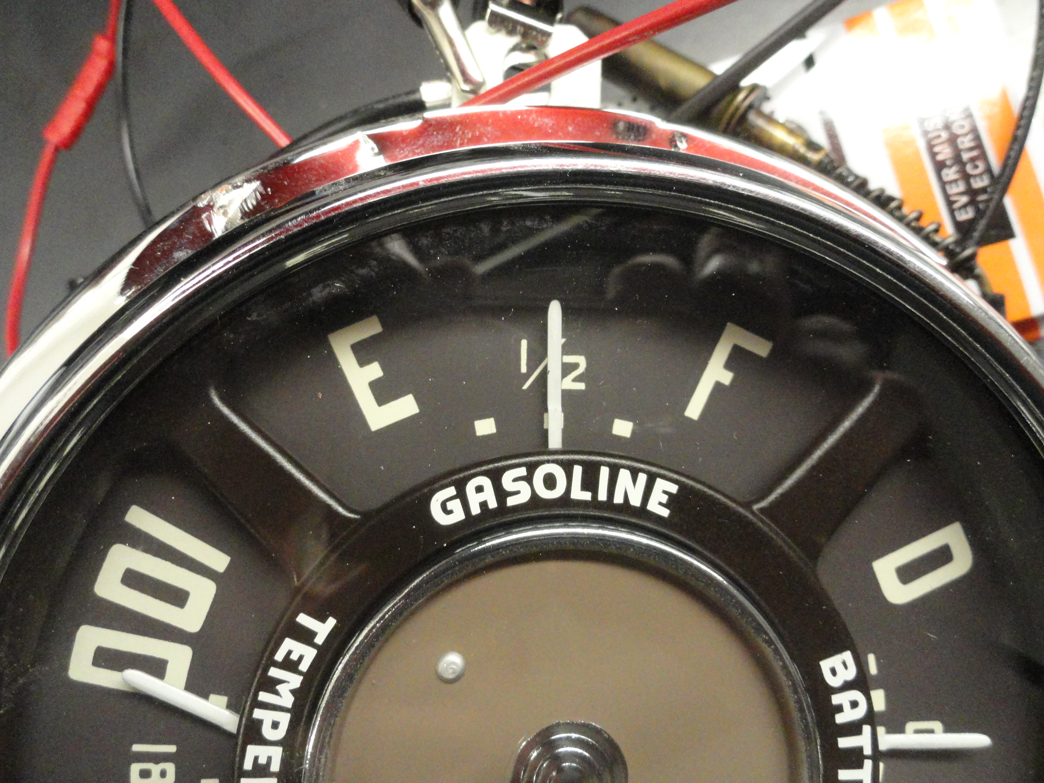
Let us not forget the reason for this Article. It is to emphasize the efficiency of NOT transferring power to heat by reducing voltage where it is totally unnecessary. This is also true with the Fuel Gauge. There are two ways to make your Stock 1947-1954 Fuel Gauge work with 12 volts; The right way, and the EASY way. To be perfectly honest, they both work. Reducers are cheaper and easier. That is NOT what we are doing here. What we ARE doing is emphasizing how to make your truck a NATIVE 12 volt system. You can't do that taking the easy way out, so bear with me, and we will figure out how to get there!
The Fuel Gauge consists of two basic circuits. One is the Sending Circuit that consists of a coil and the other is the Voltage Circuit also consisting of another coil. A Coil is an Inductor in Electronics terms and works on the principle of Induction/Impedance. Coils are measured in Ohms, and the number of windings and the size of the wire. In Mathematical terms it is expressed by: The number of turns being the square root of the impedance. We care because the way to upgrade a 6 volt gauge is to increase the number of turns thus the ohm value goes higher allowing us to run 12 volts without burning up the gauge. That said...

Here at DevesTechnet, our idea is to share knowledge on things that are sharable without ruining someone else's livelihood. Everything you see at this site is a learning process with the goal of a better understanding in mind. The few people who make 12 volt gauges for us deserve the money they make and there is no reason to teach the public how to make their own coils when these gauges are available individually via our vendors. You do not have to purchase a $300 gauge set to get a 12 volt gauge system. None of the other gauges are voltage specific so purchase the 12 Volt version of the fuel gauge and call it a day. Part of "Going Native" is to our benefit in not having heat producing step down reducers all over the place so it's a small price to pay to get the fuel gauge to go along with this Philosophy.
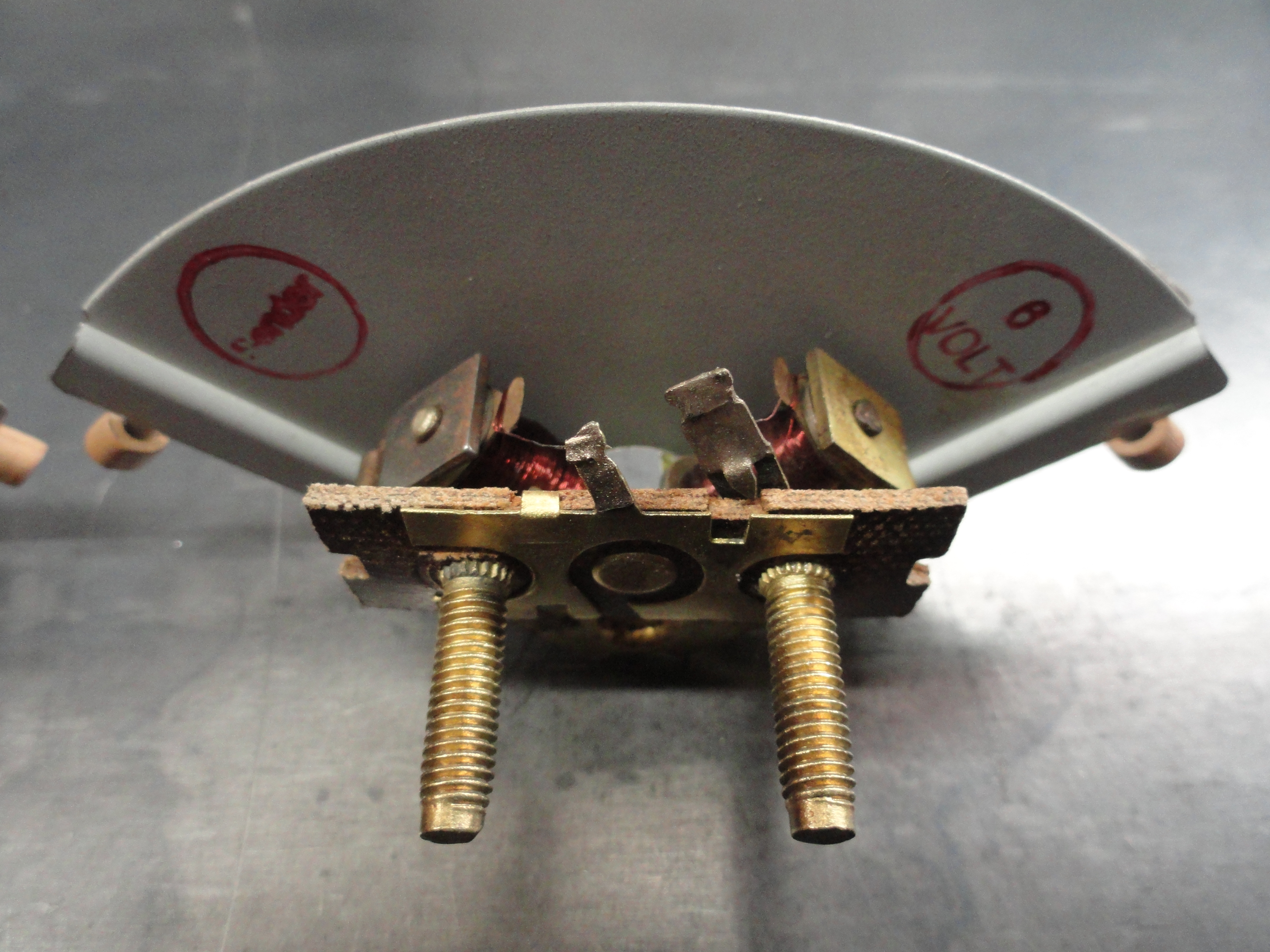
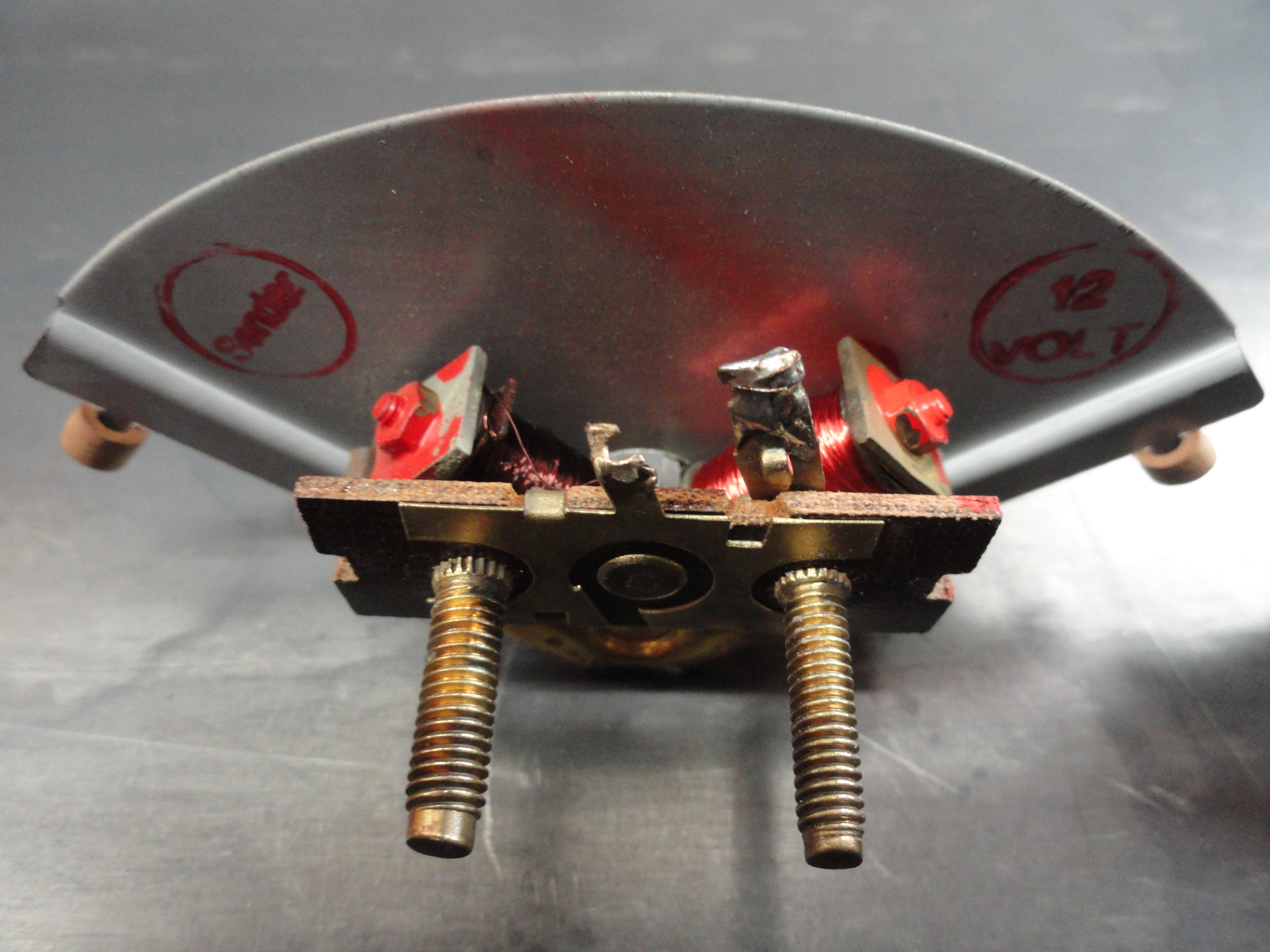
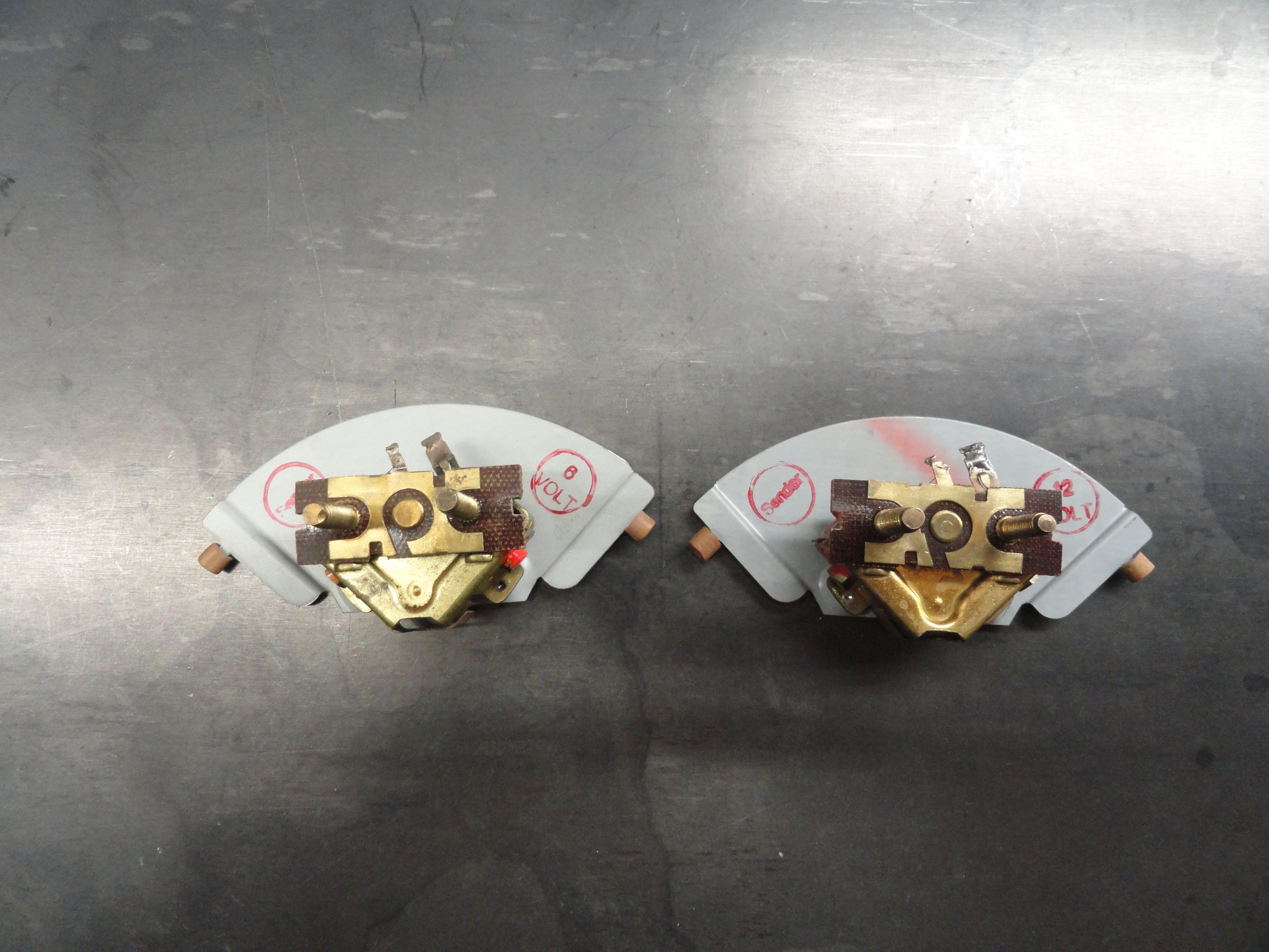
I took the time to tear a 6 volt and 12 volt fuel gauge apart so we can see what's in there. So let's take a look shall we? On the left is the 6 volt gauge, and on the right is the 12 volt gauge. While they look the same, on closer look you can see the number of windings on the 12 volt coil is increased. To be clear, the Power Terminal is behind the E on the front of the fuel gauge and the Sending Unit Terminal is behind the F on the front of the gauge. Here are a few interesting statistics:
Of course keep in mind the Sending Unit doesn't care what voltage you use with it. It is a 30 ohm Sending Unit that just provides from 0 ohms (Empty) to 30 Ohms (Full). With 6 volts applied, that is 0 volts when Empty and 1.6 volts when Full.
The Sending Unit is still 30 Ohms, but with 12 Volts applied, 0 Ohms/0 Volts is Empty, while 30 Ohms/3.2 Volts is Full. This is all academic, however, because we will purchase our Fuel Gauges and Sending Units from the Vendor. A good way to simulate a Sending unit so that you can test to see if yours is bad is to purchase a 30 ohm Potentiometer and wire it the same as the existing Sending Unit. Turn the Screw and watch the Fuel Gauge do its thing. It's a great tool to have in the toolbox. The part number from DigiKey is 3309P-1-500-ND and for $.29. That is a 50 ohm unit so disregard the top 20 ohms. To connect to emulate a single wire sender, connect the wire from the gauge to the center pin and a good ground to one of the outside pins.
Do you have other systems that use Voltage Reducers that has not been discussed here? Please let me know!