


Deve's Technical Network
1947-1955 1st Chevy Trucks
216/235/261 Engine Solutions & More
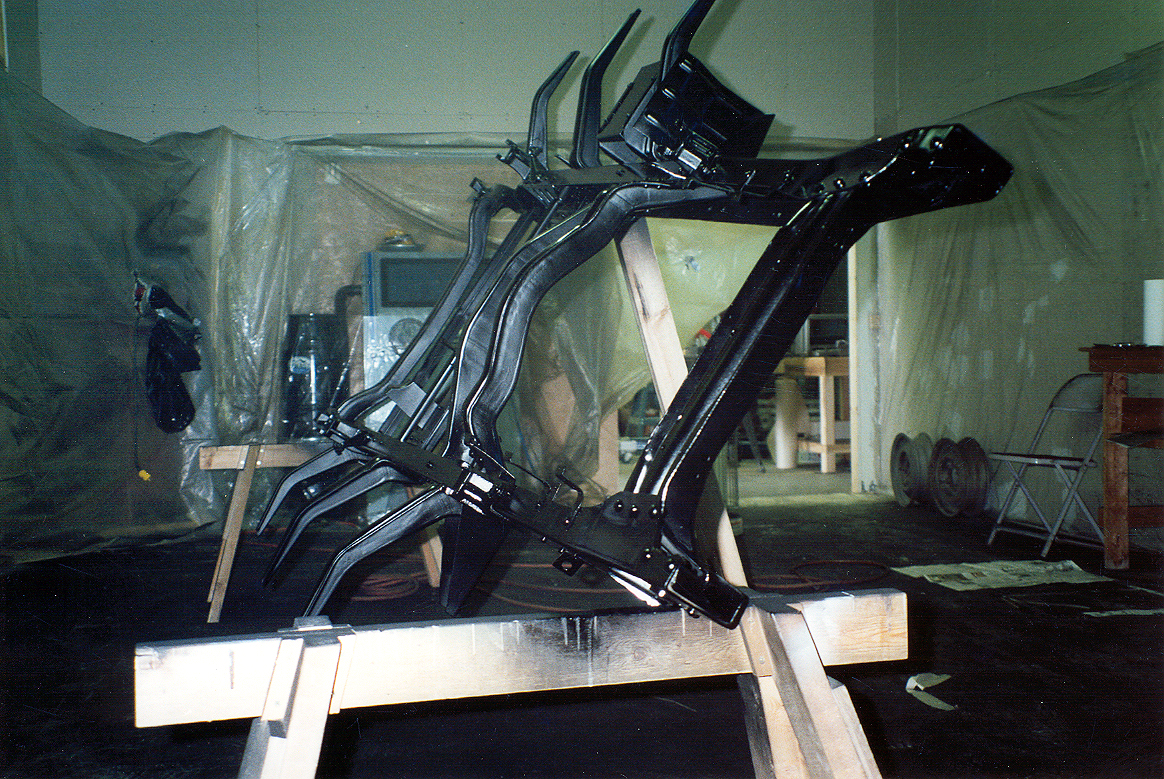
A little history... If you click on that first pic on the left there, you will see how I did my first frame up resto. Look closely at the pic and you
will see a single 2x4 propping up the frame. Imagine walking around that time after time while holding a paint gun (air hose trailing behind) and NOT
kill yourself! Let's agree it was a real dumb thing to do and never repeat it.
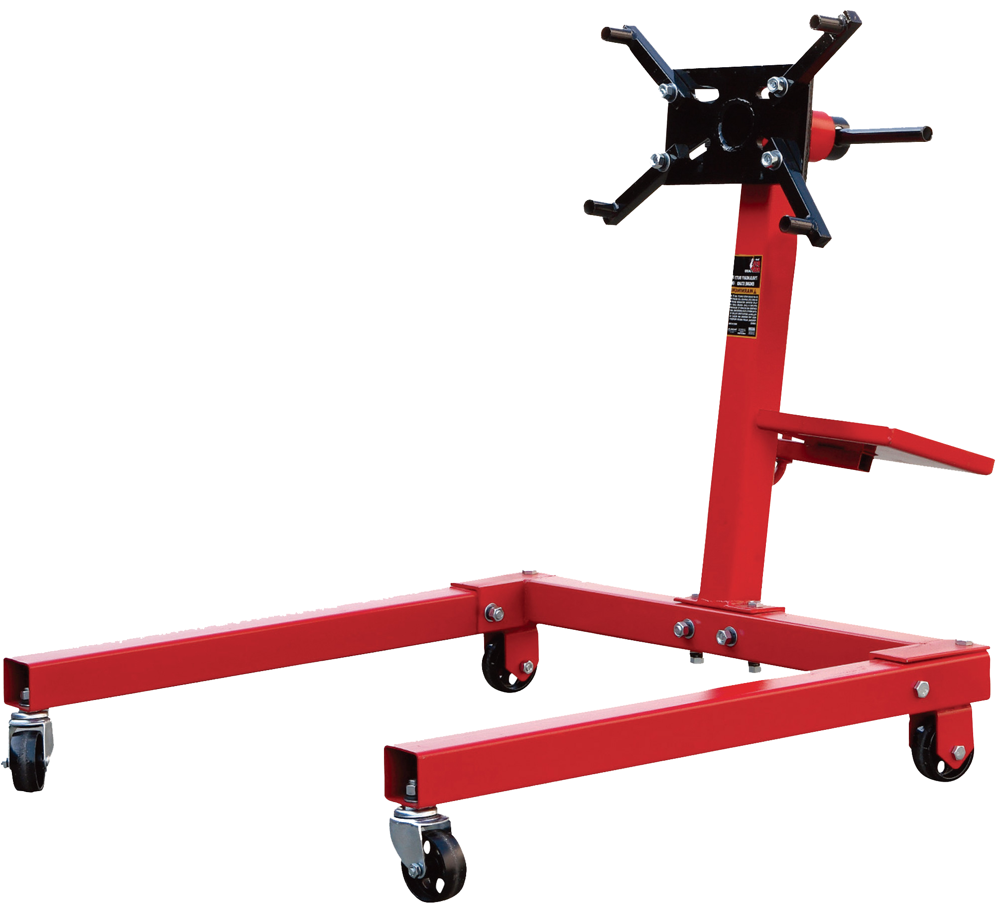
Especially since this is a relatively easy conversion. It starts off with 2 Torin Mfg. Engine Stands I purchased at Northern Tool (Item #144850). I don't put links in my How-To's for maintenance purposes, but the cost as of January, 2015 was $109. The engine stand is unsuitable for our purposes as is, because the neck of the unit is angled backwards. We need that neck to be straight, so that's where we will start. Other than that, the procedure is pretty straightforward. This style of engine stand is crucial because it has the proper legs for the span we need to make.
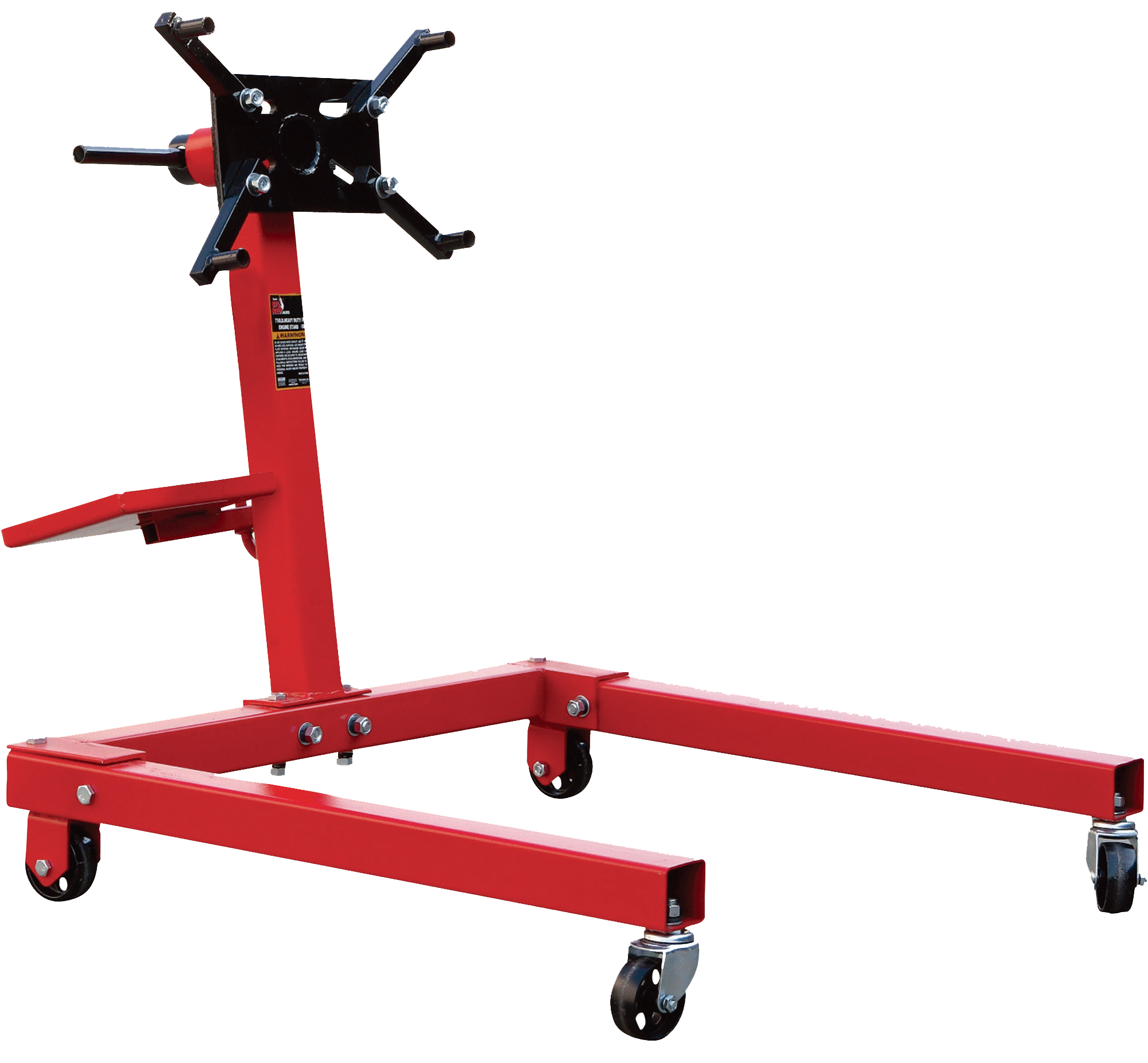
Source for the hardware including the 1" ACME Screw and Nuts was McMaster-Carr.
The best way to approach a project like this is to decide on how we want it to work, look, feel before we get started. This is where Solution Criteria comes into play. I have this policy of making the Solution Criteria set in stone no matter how hard it is to accomplish.
Now we need to make 4 brackets for the ACME screws (total). We do this out of heavy stock because there is a lot of stress on this area during use. Bend up a piece of 3/16" or thicker material that is 2" by 4". Put a 3/4" inch, 90 degree bend in it (2 inch side), then take it over to the drill press and drill a 1-1/16" hole so that the center of the hole is exactly 2 inches from the side of the neck centered on the bracket. Need 4 for the entire project. Weld it on the base with the 3/4" angle facing down as shown. Be sure it is level and do not mount the neck to the base just yet.
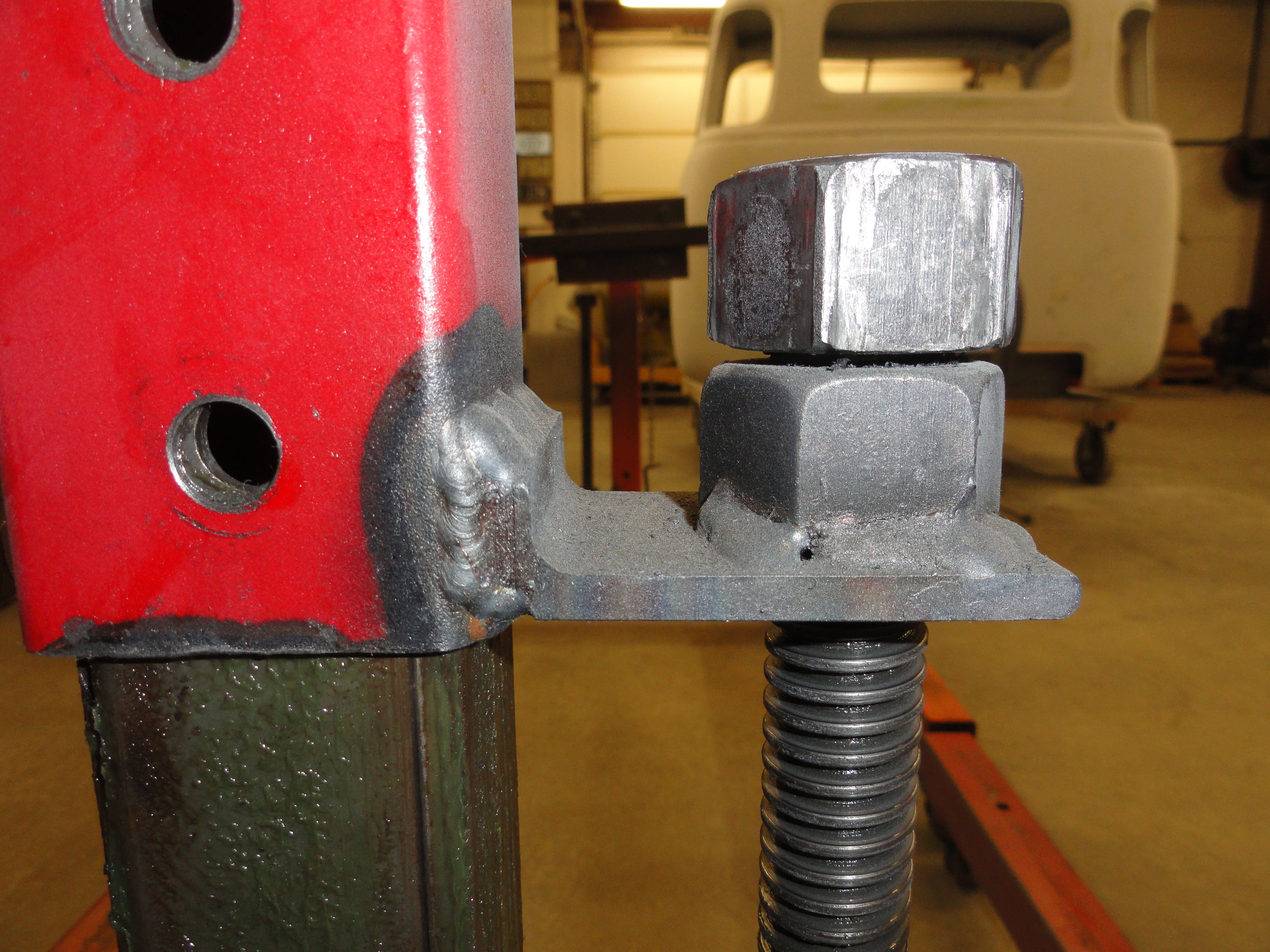
Now weld the other bracket to the outside mast as shown with the angle pointing upwards this time being sure to keep everything nice and level. Place the neck over the 2" mast and make sure the holes line up on your brackets fairly well. You will notice a lot of slop between the 2" and the 2-3/8" neck. To aid in making this more smooth and less sloppy, I cut some 1/16" by 2" wide strips about 10 inches long, spot welded them in place, then greased it. If you use the right amount of shims, it will move very nicely. Be sure to clamp them tightly before welding so they don't push away. Once you can easily raise and lower by hand, lets get to installing the ACME screw.
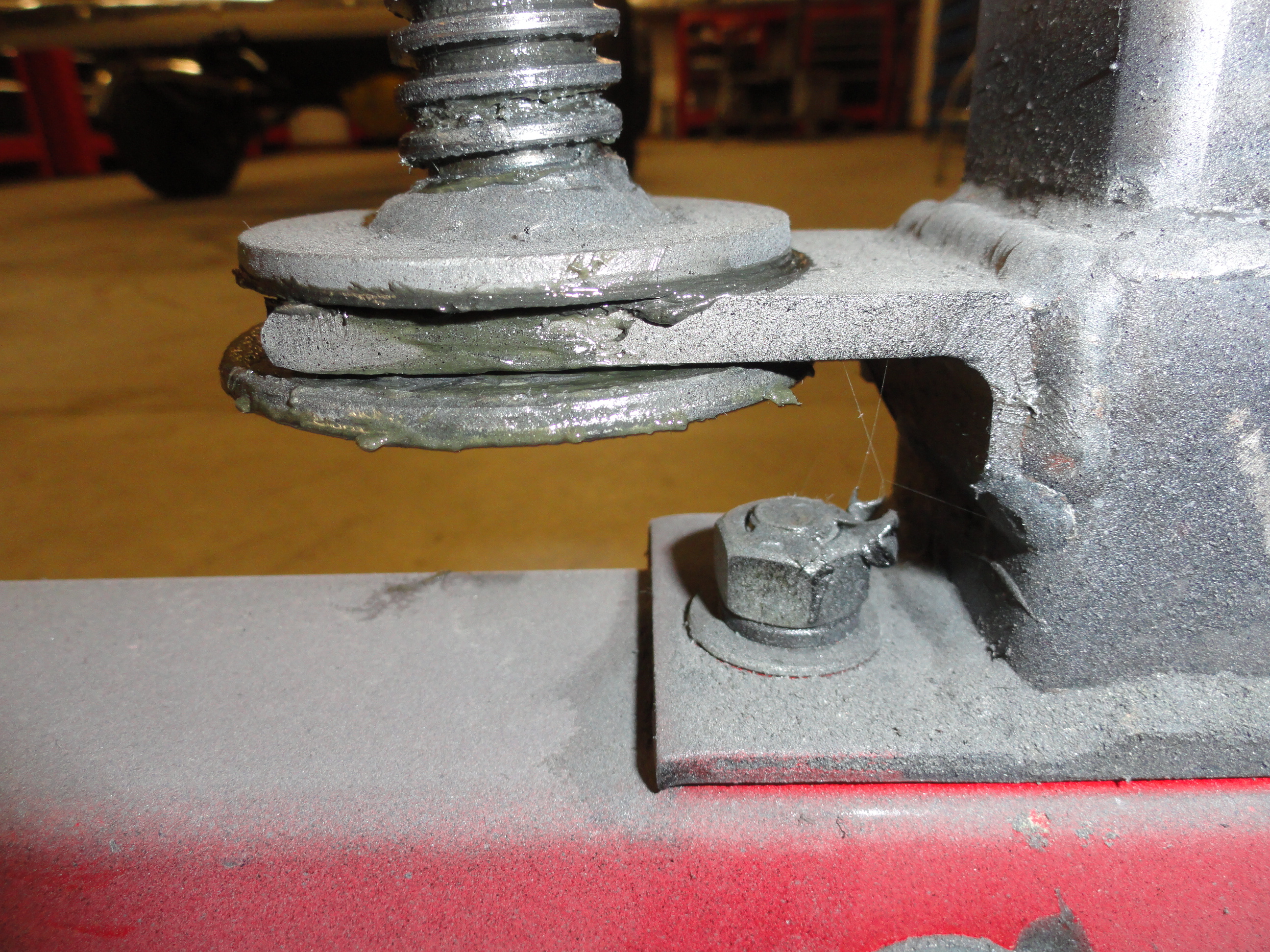
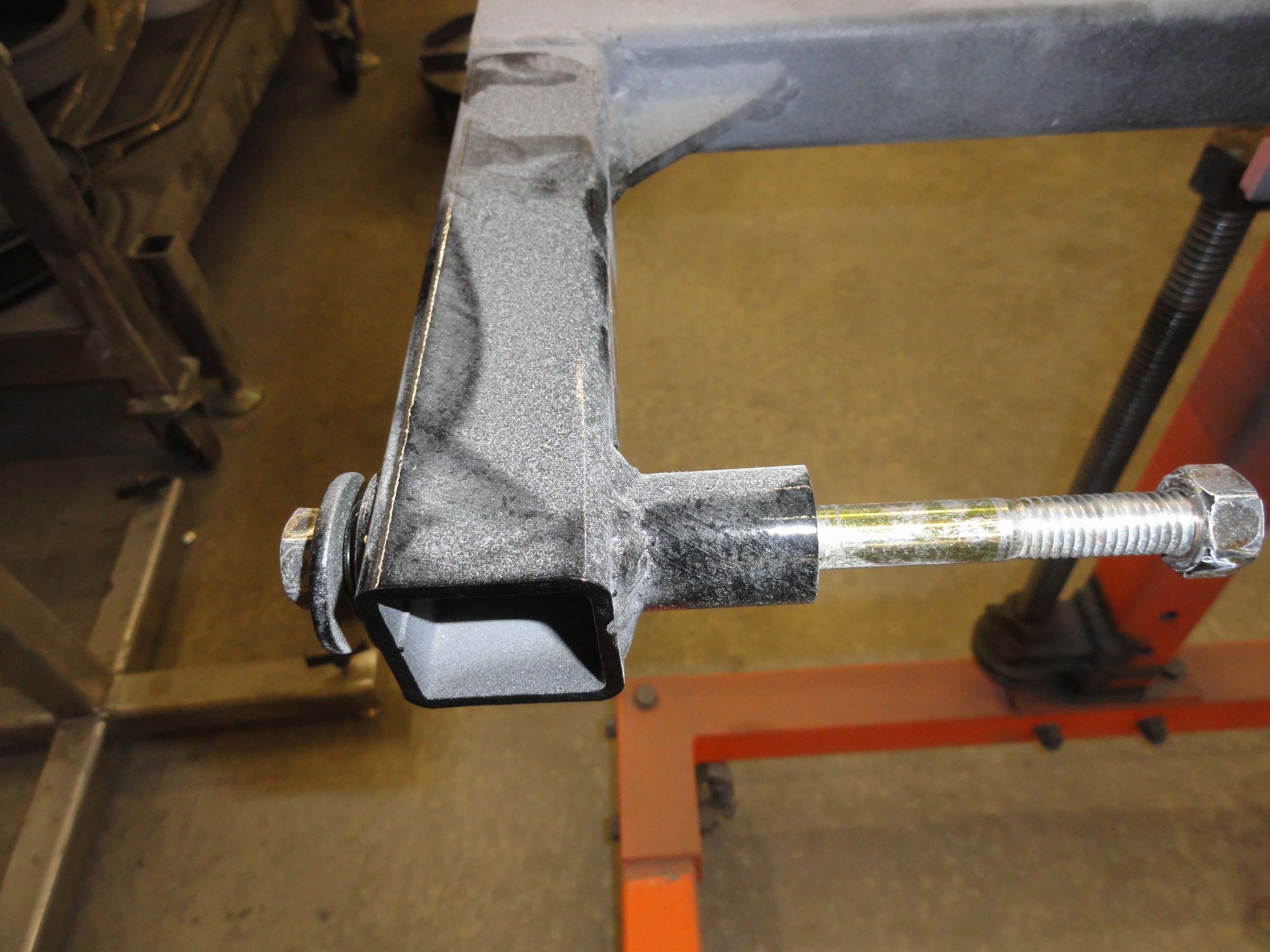
The 18" ACME screw system is pretty straightforward. First weld a very large washer on one end. Make sure its very thick and very wide. Weld it very flat since it will be turning in a stationary position and always rubbing on the bracket. INSERT THE ACME SCREW INTO THE LOWER BRACKET with the washer on the very bottom. Push the washer hard up against the bracket. To make sure we have no binding problems, take two small 1/8" pieces of flat plate stock and place them on either side of the ACME screw on the other side of the bracket, then lay your washer over it. These 1/8" pieces act as shims so that you don't weld the second washer in too tight. In other words the washers need a 1/8" clearance between them and the bracket. Weld the second washer to the ACME screw. Again, it works best when everything is straight and true and there is some slop between the two washers for movement. The ACME screw will now spin inside the bracket and cannot go anywhere.
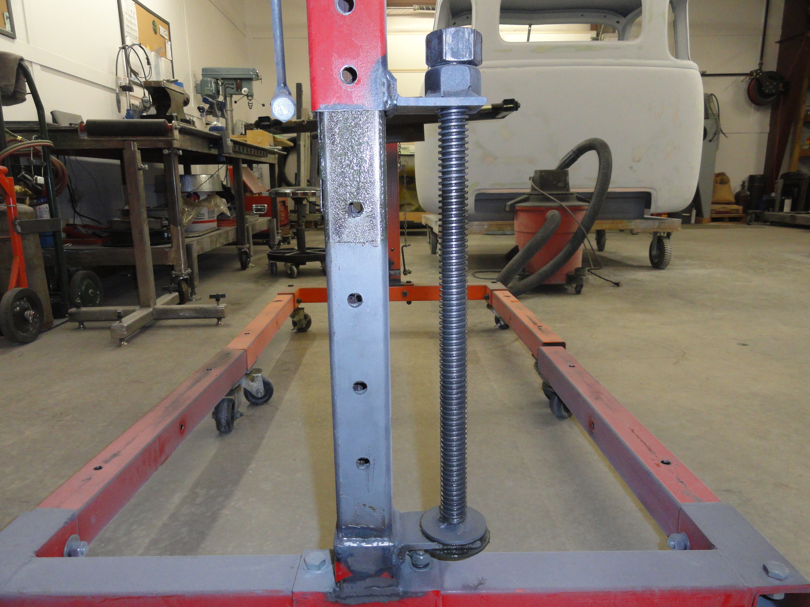
Next put the neck assembly over the mast and put the ACME screw through the hole in your mast bracket. Let the whole thing rest as low as you can get it.
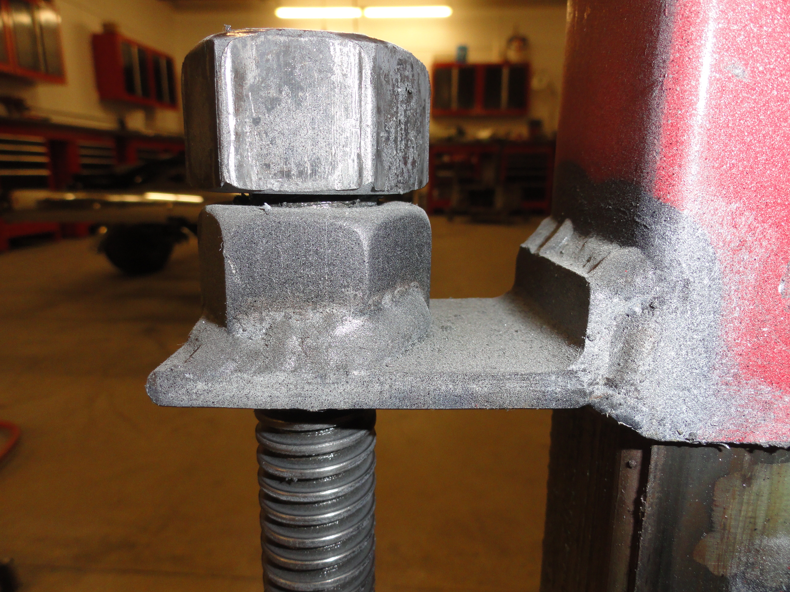
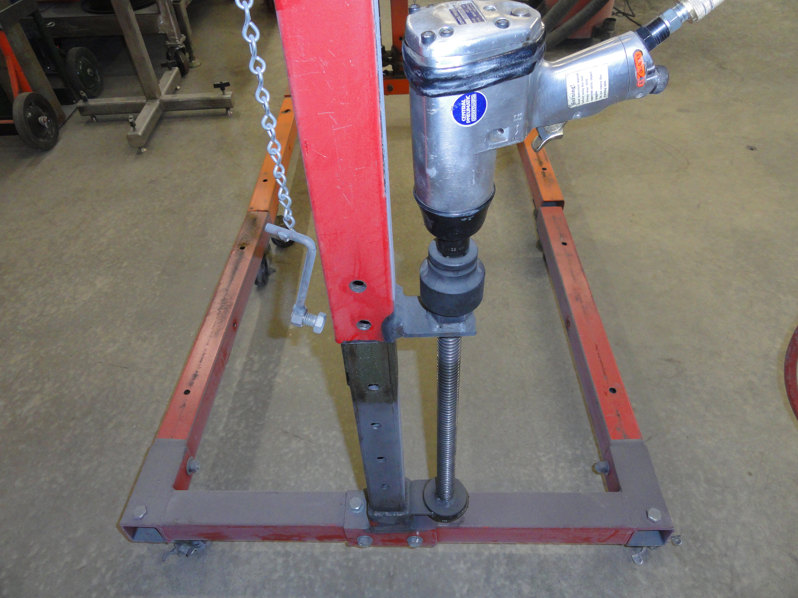
Thread on a 1" ACME Nut until it gets flush and hard against the top bracket. Weld the ACME Nut to the bracket. Now all we need is a way to turn the
screw. I welded the remaining ACME Nut to the very top of the ACME screw. Thread it in flush, then weld it from the top only. Now its just a matter of
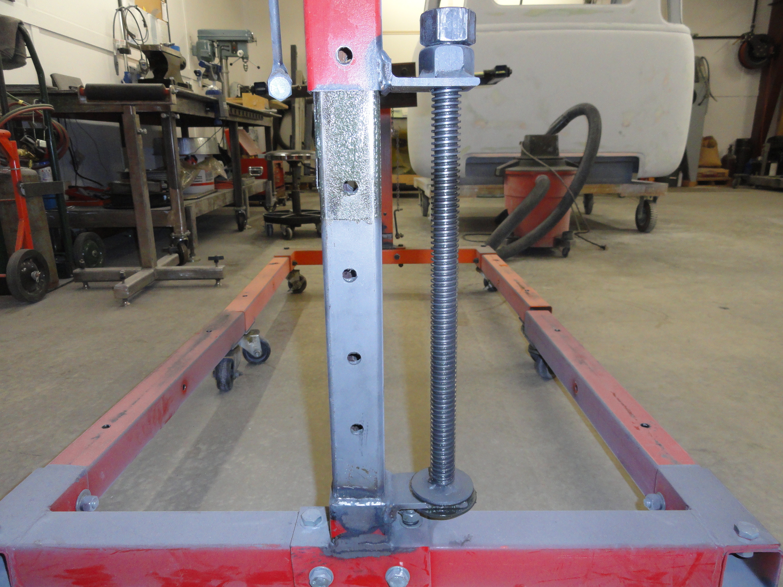
finding a 1-5/8" Impact Socket for your Impact Driver and you are set! As you can see, I also drilled holes about every 5 inches all the way through
to receive a bolt for securing in position. I did this in case I felt I needed more stability as I went up with the frame. Turns out I didn't use them,
but that option is still there. If you got this far, you should have a nice swivel base, neck mounted tightly to it, and have the ability to raise and
lower both of your carts. Great Job! You are about halfway there!
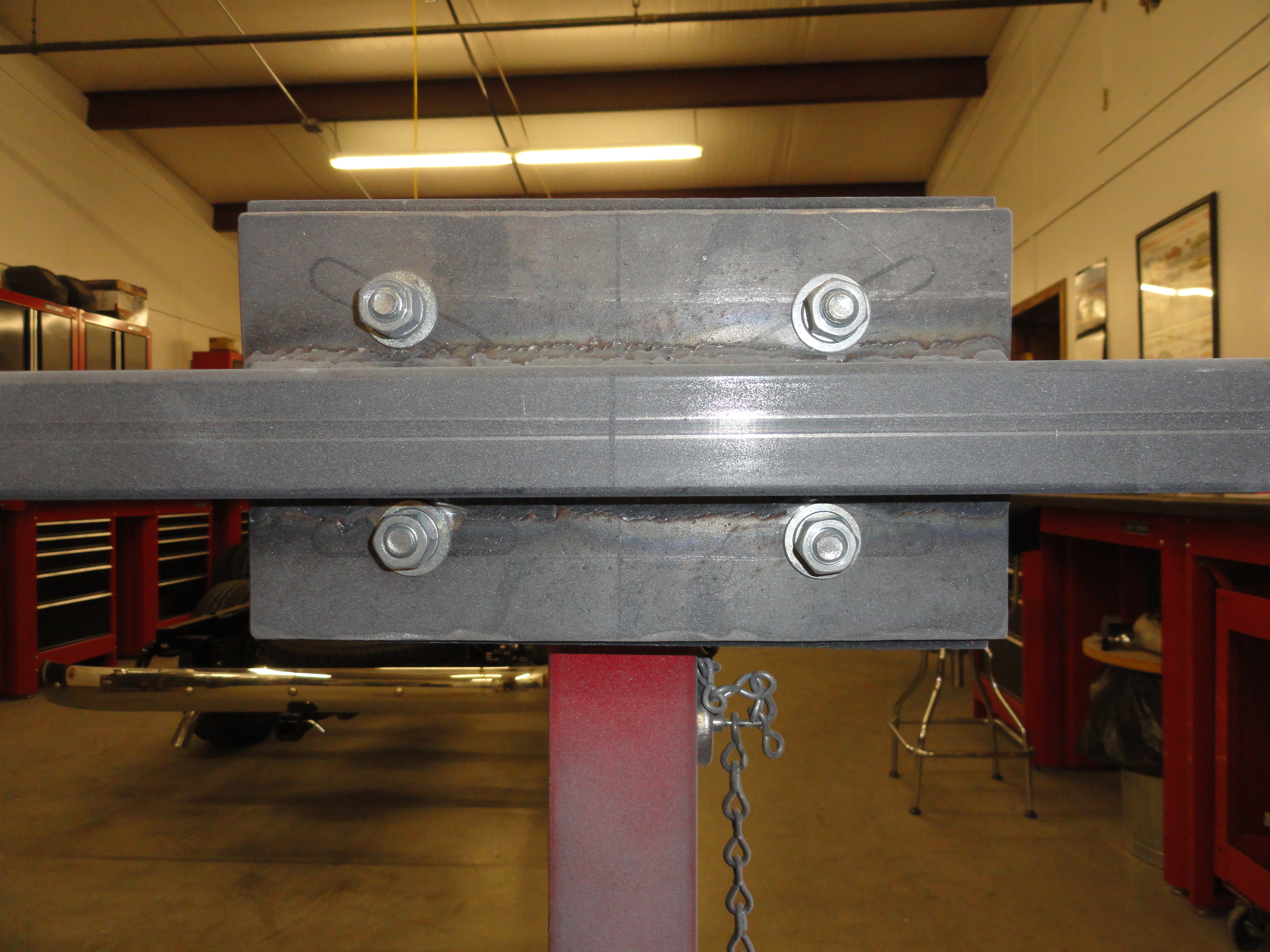
Both front and rear mounts will need the same mounting plate so make two of these. Cut a piece of 3/16" plate steel to 5-1/2" x 10". Put the plate up to the carts mounting plate and mark the holes as shown. You can put the bolts anywhere you want, except remember there has to be at least 1-3/4 inches between the top and bottom bolt sets for the cross piece to fit. Once you have that done, cut a piece of 1-1/2" square tubing exactly 46-1/2" long. Find the center of it, and the center of your mounting plate, and weld it in place. Be sure to weld it straight and even. Put a level on it.

Next, we are going downward on both sides with a 1-1/2" by 5-1/2" piece. Use a square to ensure you are getting everything straight. At this point, you want to cut some braces out for stabilizing the design. Cut a 4x4 inch piece of 3/16" plate and then halve it diagonally. Place two of these braces, one on each side in the corner and weld them in. Be sure to weld the pieces in according to the picture above. The distances are important. Next, cut a 18" piece of 1-1/2" for each side and weld to the bottom of the downward piece as shown. Put another 4 inch brace in the corner as shown.
Next thing to do for the Rear Frame Cart is to make the mounting plates. Cut 4 pieces of 3/16" plate steel to 2" by 5-1/2". Drill a 7/16" hole about 1/2" from the top and round the corners as shown. Weld them in straight and true, then take a piece of 2 inch square tubing and re-shape those pieces so there is a nice 2 inch gap between each set of brackets. This is where your rear leaf spring perches will be bolted to. Use the 4" grade 8 bolts for this purpose. The geometry of this mount is such that it makes for really easy rotation.
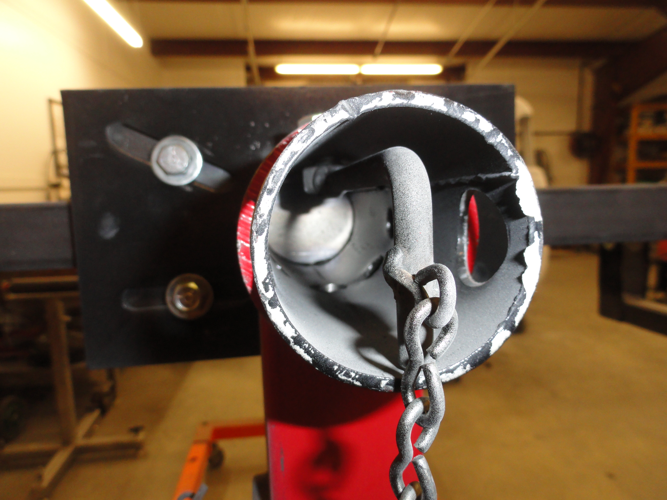

Almost done with the rear cart. Lets work on the center rotator pivot on both of them. It was sorta handy that this big center pivot was part of an
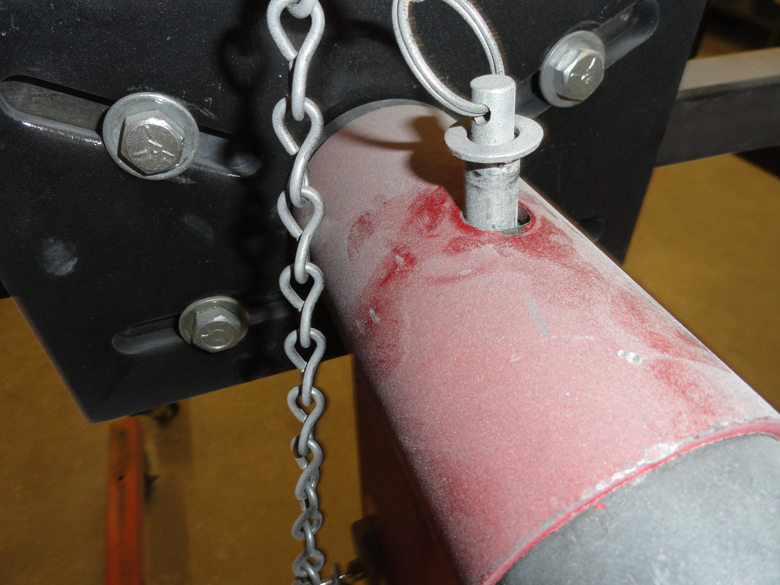
engine stand. We didn't have to make it ourselves. Very nice! On the very top of this round assembly is a hole for pinning it in place. The round inside
part has holes every so often so when you turn it, you can lock it down at most any angle. The problem is, this hole is a bit too big for the pin so
there is a great deal of sloppiness that you don't want when you are board sanding, or putting any pressure on the frame.
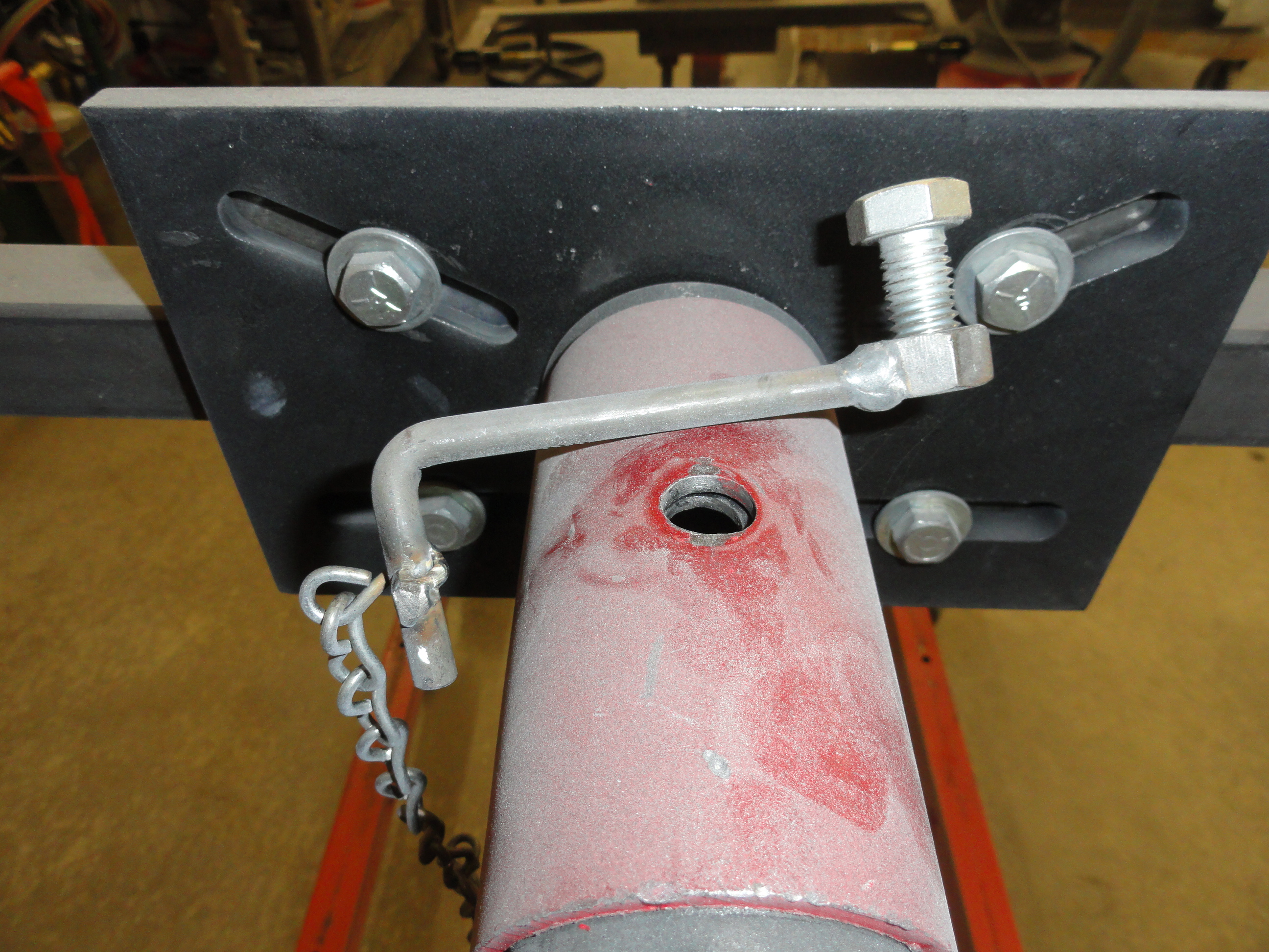
My solution was to cut a piece
of solid 3/8" steel rod 5-1/2" long and weld a 1/2" nut on the end of it, then bend this rod on the other end 1-1/2" inches down to 90 degrees. Slide the
nut into the pivot under the top hole, then drop a 1/2" x 1" bolt through the hole and tighten. End of problem. I then put this unique tool on the end
of a chain and hung it on the side of the mast with a magnetic hook. I also did the same with that cheapo pin that came with the engine stand, so if I
don't need it super secure, I can just pin it in place.
You want to make sure the cross handle bar is in place when you have a frame on these carts. The only thing keeping that center pivot from pulling out
is that handle! It's a good idea to add grease to that pivot every now and then. Also a must to grease the ACME screw, especially at the base where the
washers are. Now that we are done with the Rear Cart, lets finish this project up!

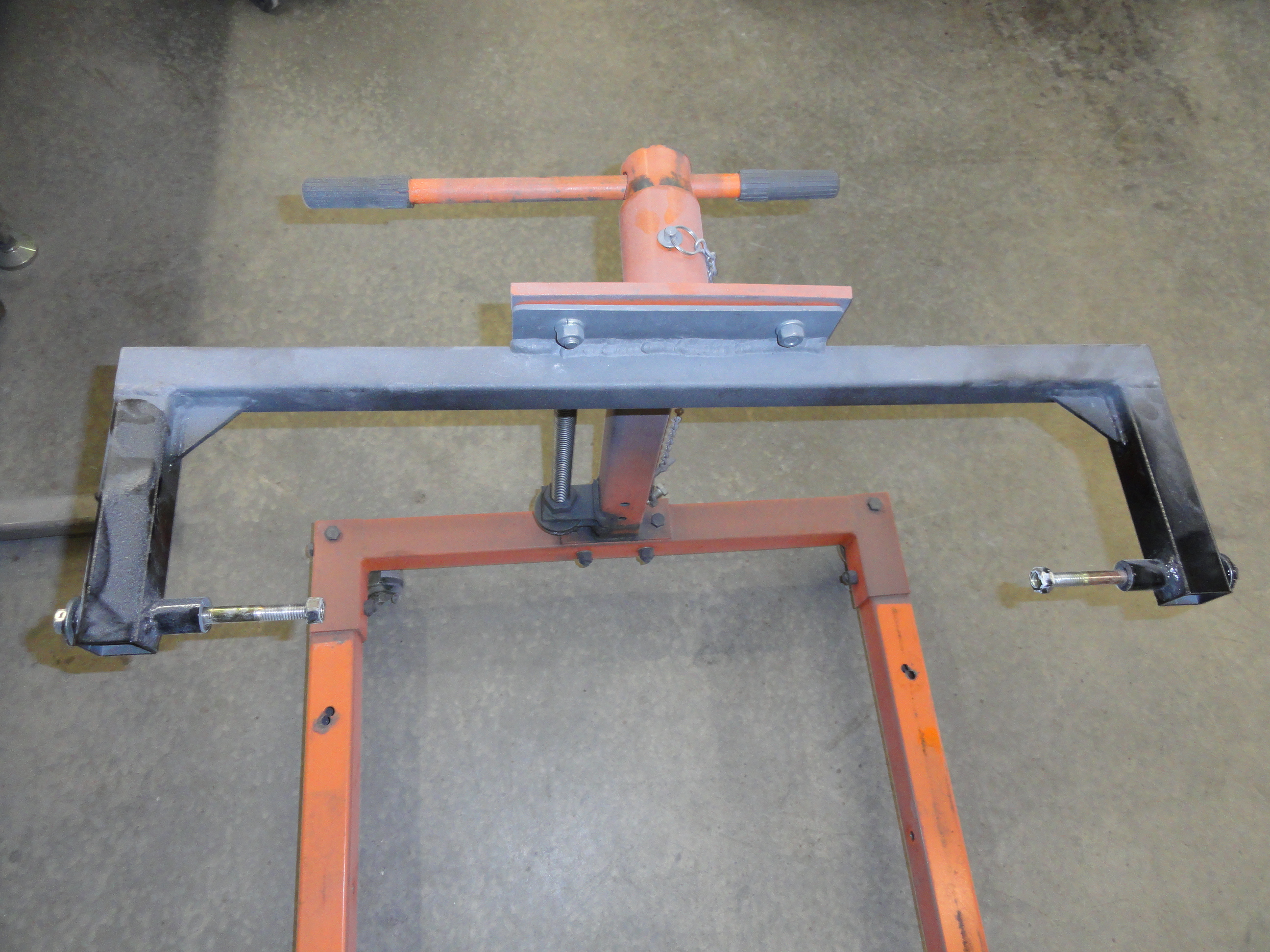
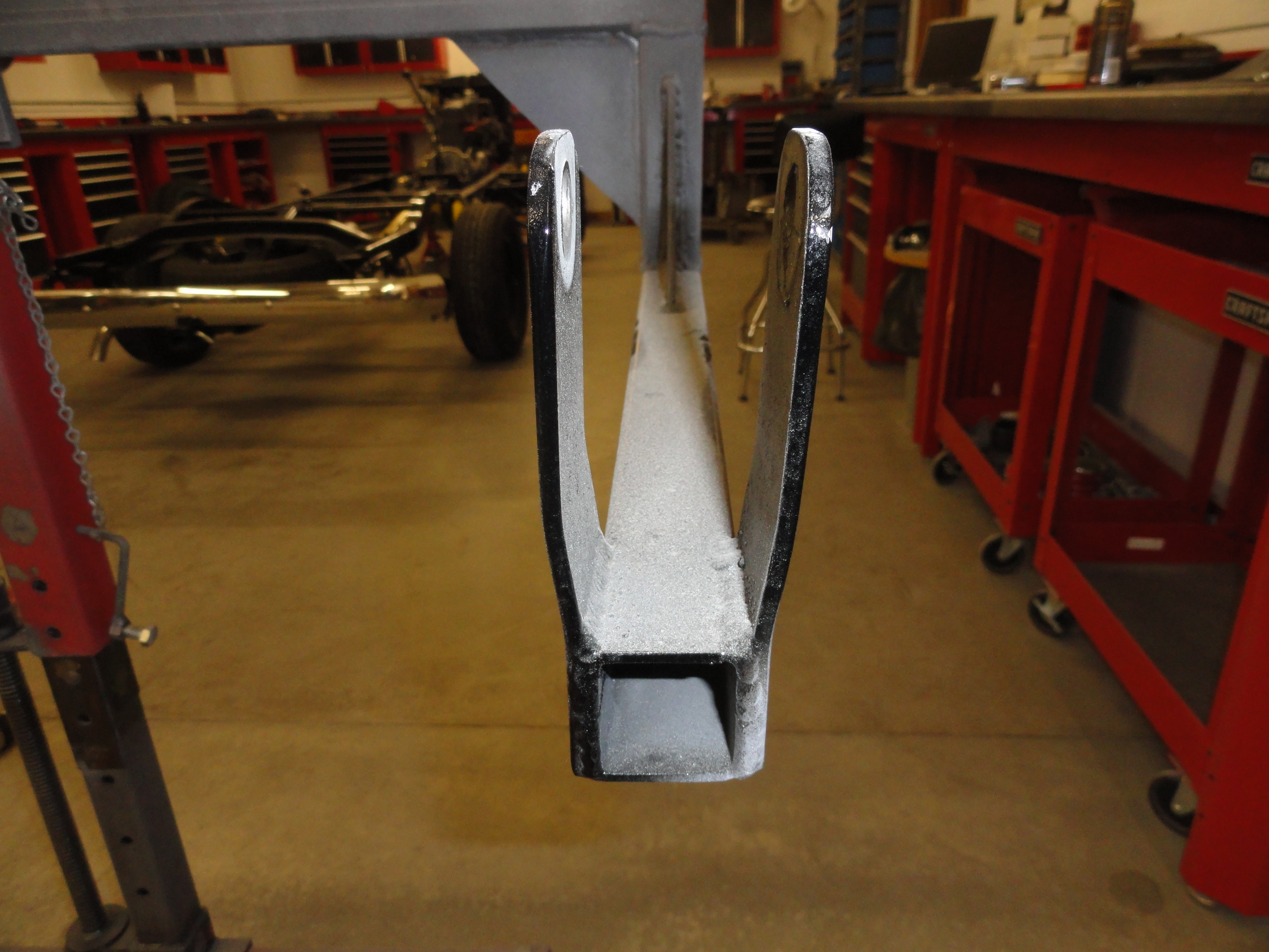
We will proceed the same way we did with the rear mount by finding the center of a 31-3/4" piece of 1-1/2" square tubing. Weld this cross piece in the center of the mounting plate as shown. This time we only have to weld arms to this cross piece. Cut and weld 7" x 1-1/2" square tubing as shown. Cut two 2 inch diagonals out of a 2" x 2" piece of 3/16" material. Weld them in to give that arm assembly some support. Now drill a 7/16" hole about 1/2" from the end all the way through the 1-1/2" tubing. Put a bolt through the hole and be sure its long enough to tighten down the 1-3/8" spacer needed to support the frame. Tighten it down with a washer and nut then weld the base of the spacer to the tubing as shown. This is exactly the space needed to support the front leaf spring support at the front of the frame. Now you just put the long bolt through the frames leaf spring hole, tighten down and you are done.
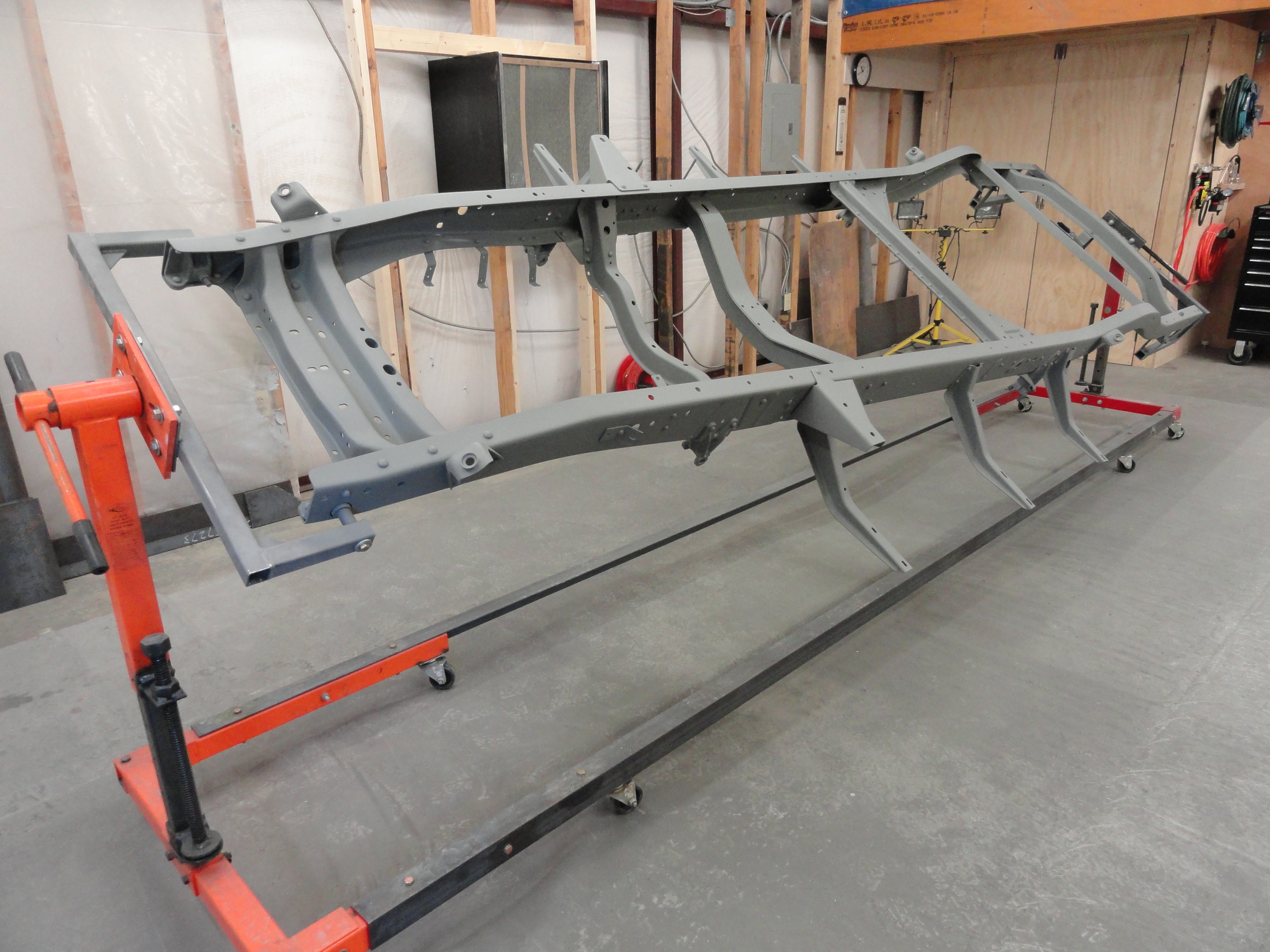
The final assembly step is to attach the 3" by 15 foot angle iron rails to the carts. This is quite necessary because the individual carts do not
cooperate with each other without this. This heavy solution adds weight in the right place and really makes this system stable. To make sure you
connect them properly, put the frame on the carts and once it's secure, clamp the rails firmly in place then drill two holes through everything on
top and on the side for 3/8" bolts, nuts and washers. Fasten securely. When I am done with the Rotisserie, I always just tuck those long rails under
a bench somewhere out of mind.
The idea is to push these carts up to the front and rear of the frames at the height it is sitting, adjust the cart, temporarily support the end of
the frame you are working on, bolt this thing up, do the same on the other end, and raise so that the running board brackets clear the floor when you
are rotating it, and everyone is happy. Once you are have the frame ready for putting back on the leaf springs, reverse the process. This cart is great
for all repair, preparation, sandblasting, and finish painting. It has been a real success in my shop for sure!