


Deve's Technical Network
1947-1955 1st Chevy Trucks
216/235/261 Engine Solutions & More
We are going to take a Distributor from a 1959 235 Engine and convert it from a points/condenser system to an HEI system without modifying any of the vintage parts. If you do not like this mod after you have tried it, or for any reason want to go back to a points/condenser system you can. Here is the Solution Criteria we went by to make this happen:
Generally when you think of HEI for this vintage, you think of Tom Langdon's HEI offerings, or Pertronix adapters. Both are just fine and we encourage you to do your research, but in our case, we want to use the stock distributor without ruining the points mounting tower, the points cam lobes, or the points cam screw that is affixed to the internal distributor plate. In fact we will do NO modifications to the distributor itself. The reason this modification is not a common one by now is beyond me. Let's get into it...
What are the advantages of HEI? A few of them are more consistent firing, no points to adjust, fewer moving parts. Since the spark is much hotter, wider plug gaps, thicker spark means a more complete burn of leaner fuel mixtures. This will improve engine performance and reliability. As one of the instructors at one of the countries foremost automotive colleges put it: "The HEI as built by GM could very well be the best overall ignition system out there ever. It has a varying dwell based on engine RPM and a ramp and fire circuit using 3.6 ms and 5.5 amps output with current control. Arguably, this will improve engine performance and reliability.
A really nice, well done project along these same lines can be found at The Greasy Gringo. Our friend Jason McElroy did this already. What we want to do is expand on this idea. We can't thank Jason enough for his pioneering efforts. So, just because one person did it, does that mean we should too? So, I got an email out of the blue from another new friend, Jim Linder of Linder Technologies. He runs Bubba's Hot Rod shop in Indianapolis. Jim has been an Ignition Technology Instructor for the past 30 years and has been very helpful in answering my questions. He is retired now, but used to offer the service of modifying your 216/235/261 Distributor pretty much exactly the same way Jason describes. Check out Bubba's Hot Rod Shop. What we want to do is expand on this idea, explore ways to make it even better. Better because the way we are going about it does not damage or change in any way, any of the vintage parts.
After doing a little research on parts, the parts Jason and Jim used seem to be the most available and the easiest to fit into
this very tight space. To be more specific, the Reluctor and Reluctor Pickup units are out of the 1972-1985 slant 6 Mopar.
The brains (HEI Module) for all this is a GM design. The parts list is as follows:
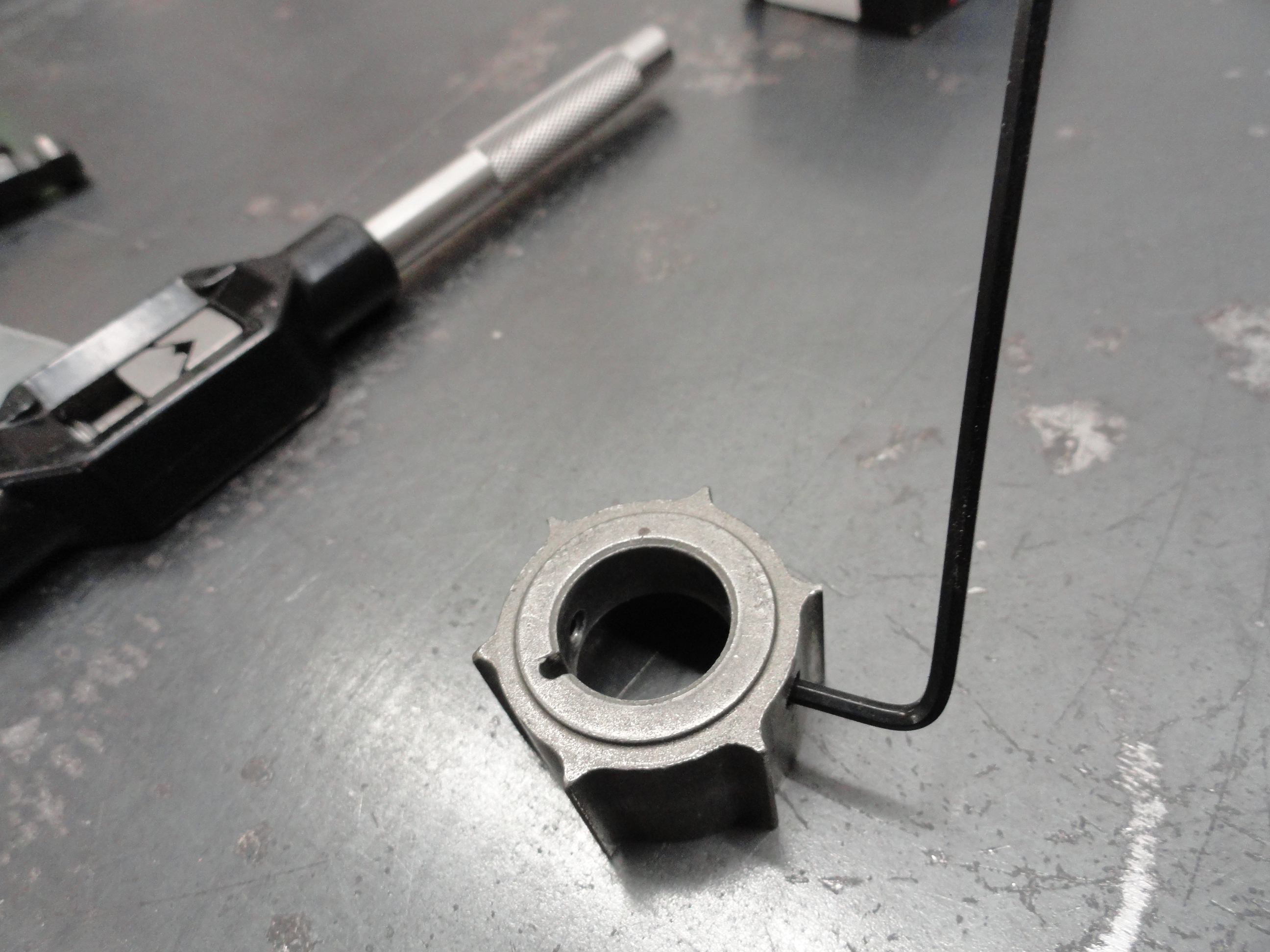
After a bit of research on reluctor technology, the one that we chose comes out of a 1972-1985 Slant 6 Mopar. It fits our distributors like it belongs there. We did search hard for a GM reluctor that would be appropriate but nope, this is the perfect one for our application.
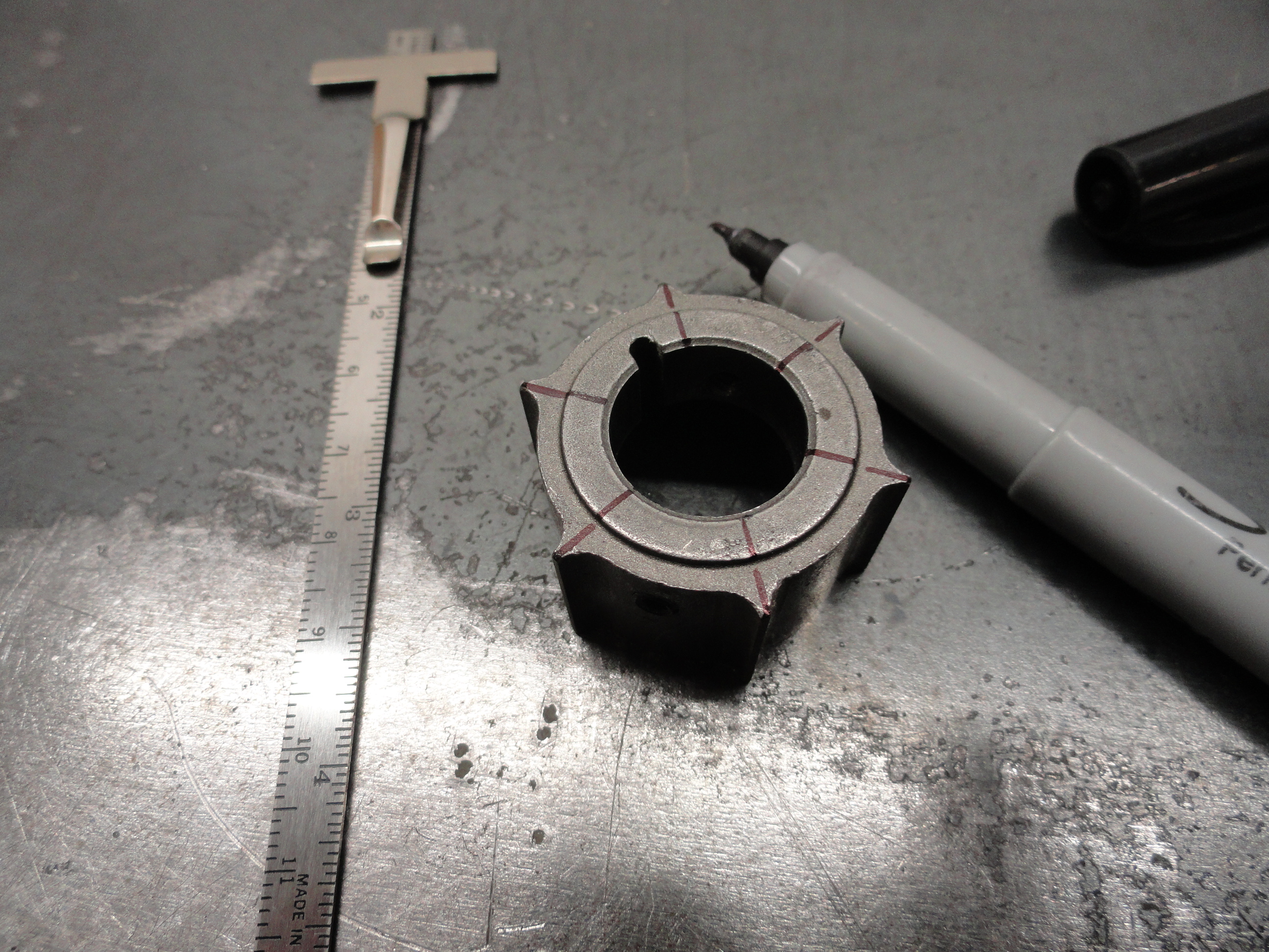
Drill the reluctor for two 8-32 (1/4" long) set screws. Use a #29 drill bit. My set screws required a 5/64" Allen Wrench. Back them out or remove them entirely for the next operation which is the lobe grinding process. Remember, no modifications to the Distributor itself. The actual lobes on the Distributor happen to be 5/8" hexagon. You can turn your Dizzy all day with a 5/8", 1/2" drive Long Socket. Drill these set screws on the thick part of the reluctor as shown. I just drilled both at the same time to get them across from each other perfectly. If you set the reluctor flat like I did in the vise, the holes come out really nice. Use a standard clean and sharp 8-32 tap to finish the part.
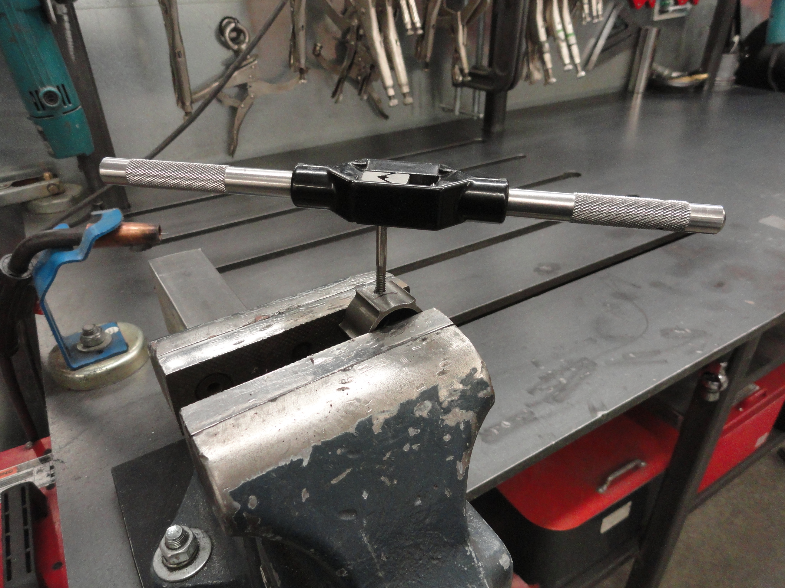

Using the Dremel Model 220 Drill Press attachment, with a fine straight shanked rasp with the 1/8" diameter made pretty easy work out of cutting the hexagon shape out of the center. Remember not to take off very much material. The reluctor is already 5/8" round diameter inside, and we are making it 5/8" hexagon. This took about 45 minutes to do because there is lots of fitting and refitting involved. It MUST be tight when you are done.

Don't have a Dremel Model 220 Drill Press attachment? Use your drill press and get the same bit I used, and it should work as well. Be sure
to use the highest RPM you can get your machine to muster!
Start by marking across the reluctor as shown. Then, keeping the reluctor so that the lobe you are attacking is directly across from the line
in front of you, push the reluctor gently into the rasp and move the Dremel's lever up and down to make a groove top to bottom, as shown.

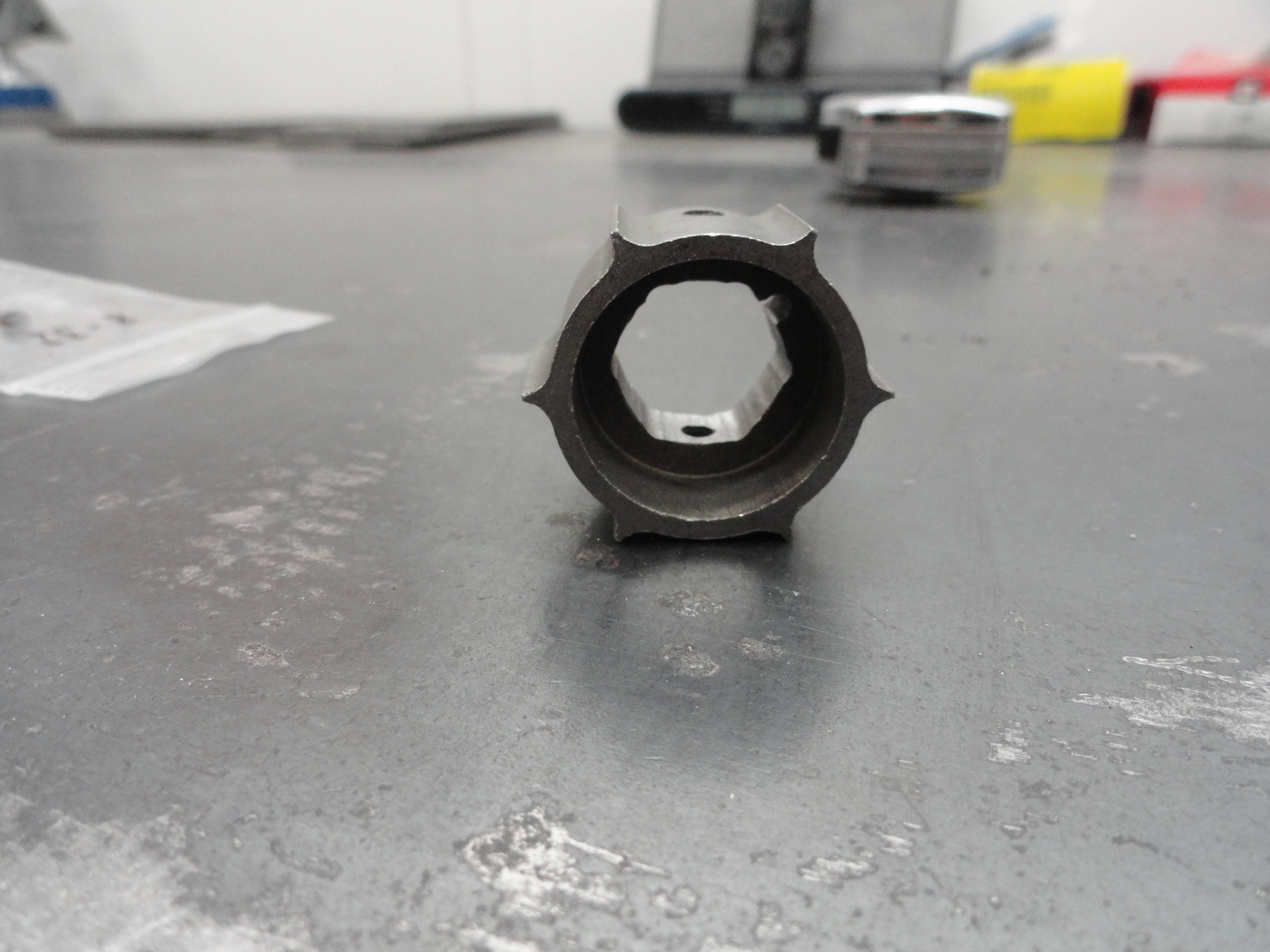
Especially notice the placement of the reluctor on the tool. You want to make 6 equal such grooves. I can't express the importance enough of taking this S-L-O-W. Remember its a 5/8" hole already. There isn't much to take off and still have it fit tightly. And, it needs to fit 100% tight otherwise you will have trouble with the .007 clearance on all 6 lobes between the reluctor and pickup. Do all 6 lobes with equal pressure and depth then dry fit on the distributor, over and over. Once all lobes have a distinctive 6 sided shape, carefully move the reluctor on the tool side to side to square the sides with the grooves. Do all of this very slowly! When you are done, it should fit tight without the set screws. Not like you have to hammer it in, but snug push in, pull out by hand.
Once you have your tight and consistent fit, tighten down the set screws and test to see if it's wobbling or hitting anything. Mine came out very nice the first time. (Truth be told, if I can do it, anyone can). No sense in letting the reluctor scrape the bottom plate. Pull it up a little so it turns smoothly and doesn't bottom out. If you did it right, your rotor will sit on top like it always does and even if 'just barely' your reluctor isn't hitting anything.
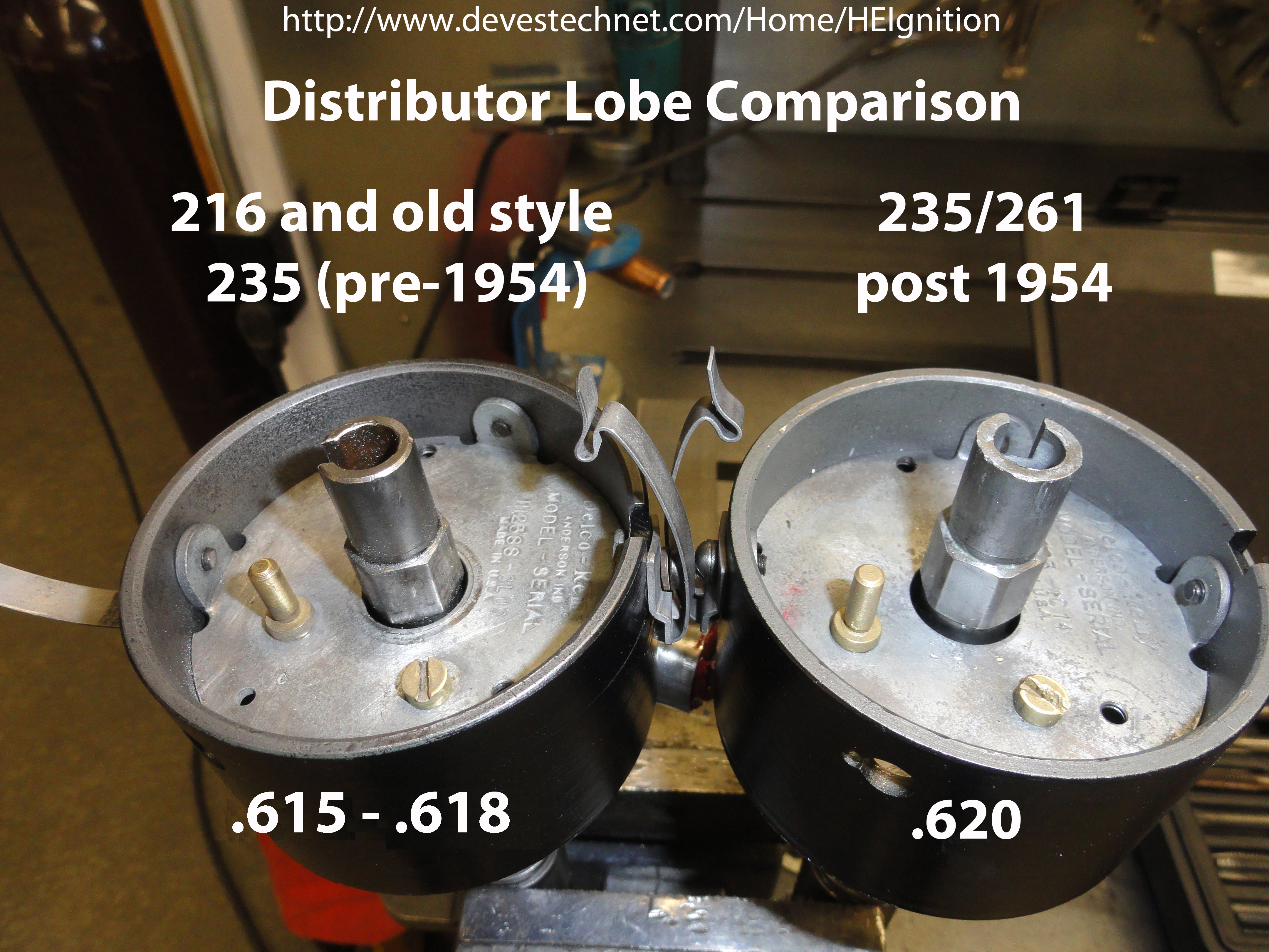
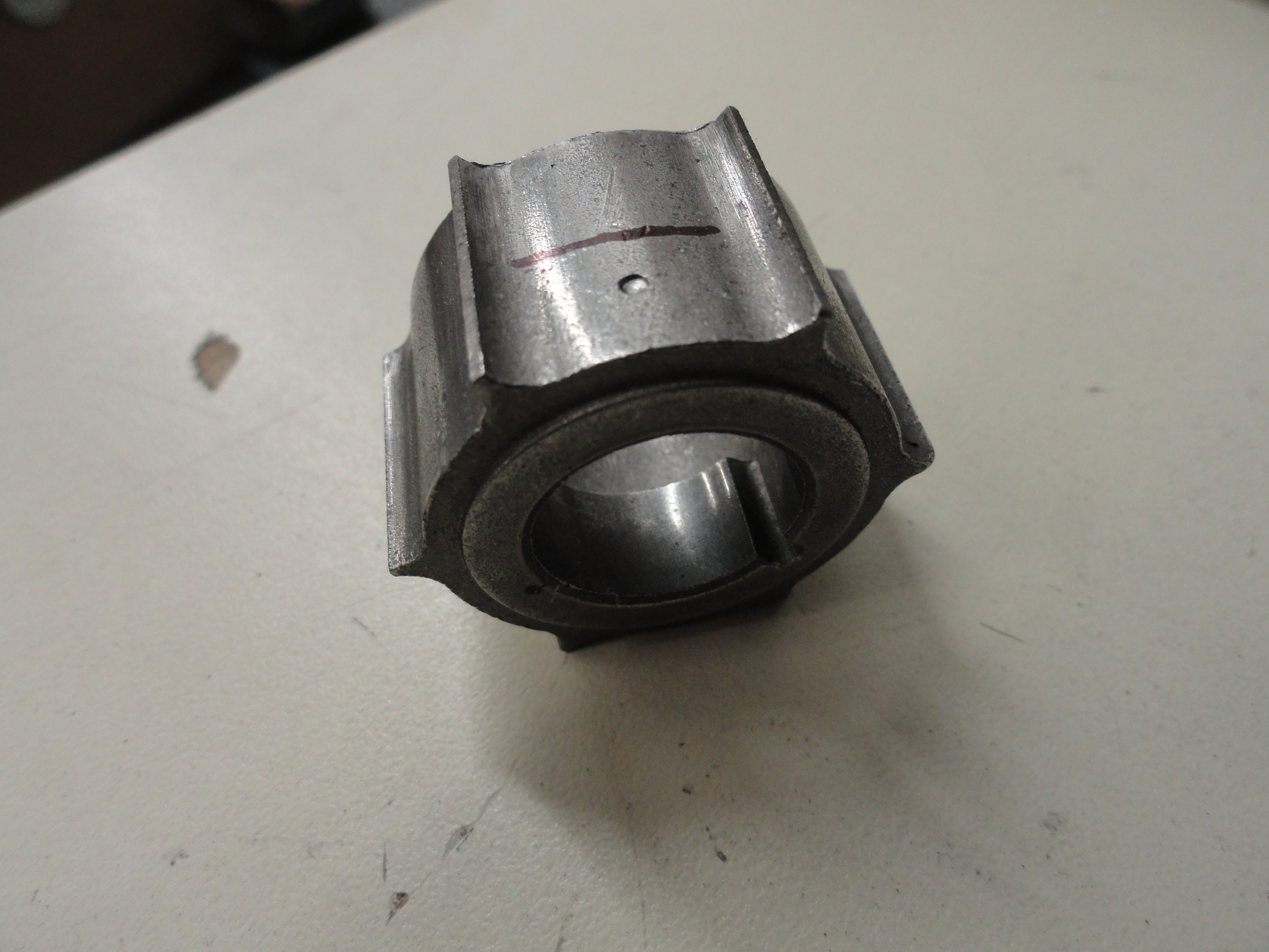
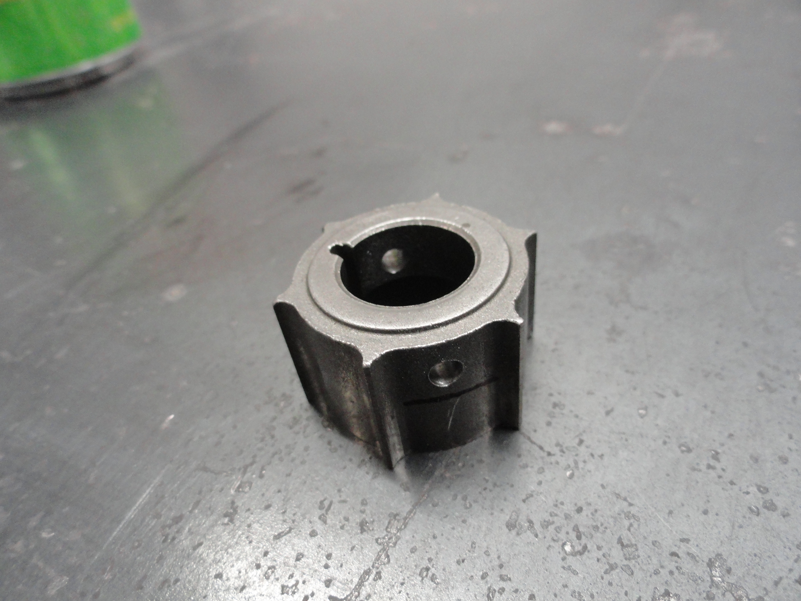
 Important! After doing this on various distributors it was discovered that there are two distinct types of distributor lobes
depending on the engine/year. The old style 216/235 engines prior to 1954 have lobes on their distributors that are sharp. The 1954
and later ones have lobes that are rounded. This is not due to wear! This is important because the lobes are also different sizes! The
older ones can vary between .0615 and .0618 and the newer ones are pretty consistent at .0620. The picture on the left is a 216
distributor left and a new style 235 distributor right. Since .625 is 5/8" we do not want the reluctor to be sloppy once it's in place.
Important! After doing this on various distributors it was discovered that there are two distinct types of distributor lobes
depending on the engine/year. The old style 216/235 engines prior to 1954 have lobes on their distributors that are sharp. The 1954
and later ones have lobes that are rounded. This is not due to wear! This is important because the lobes are also different sizes! The
older ones can vary between .0615 and .0618 and the newer ones are pretty consistent at .0620. The picture on the left is a 216
distributor left and a new style 235 distributor right. Since .625 is 5/8" we do not want the reluctor to be sloppy once it's in place.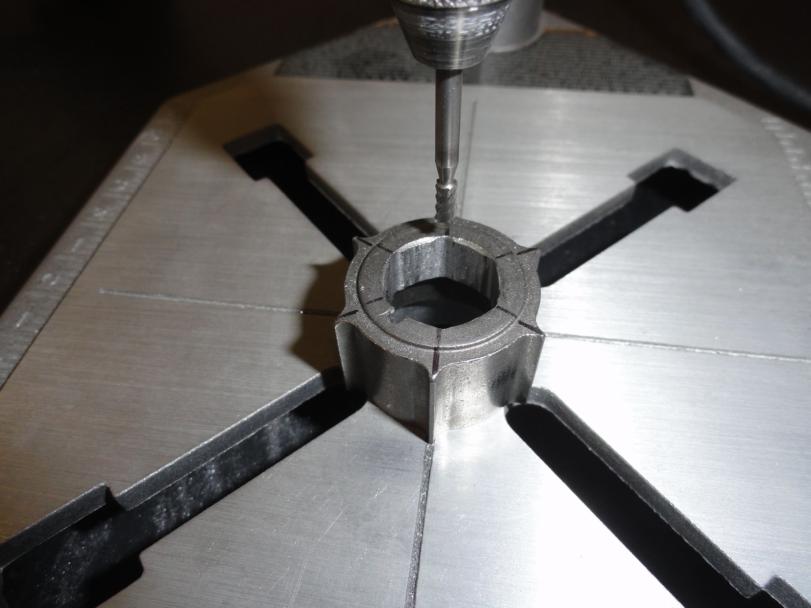

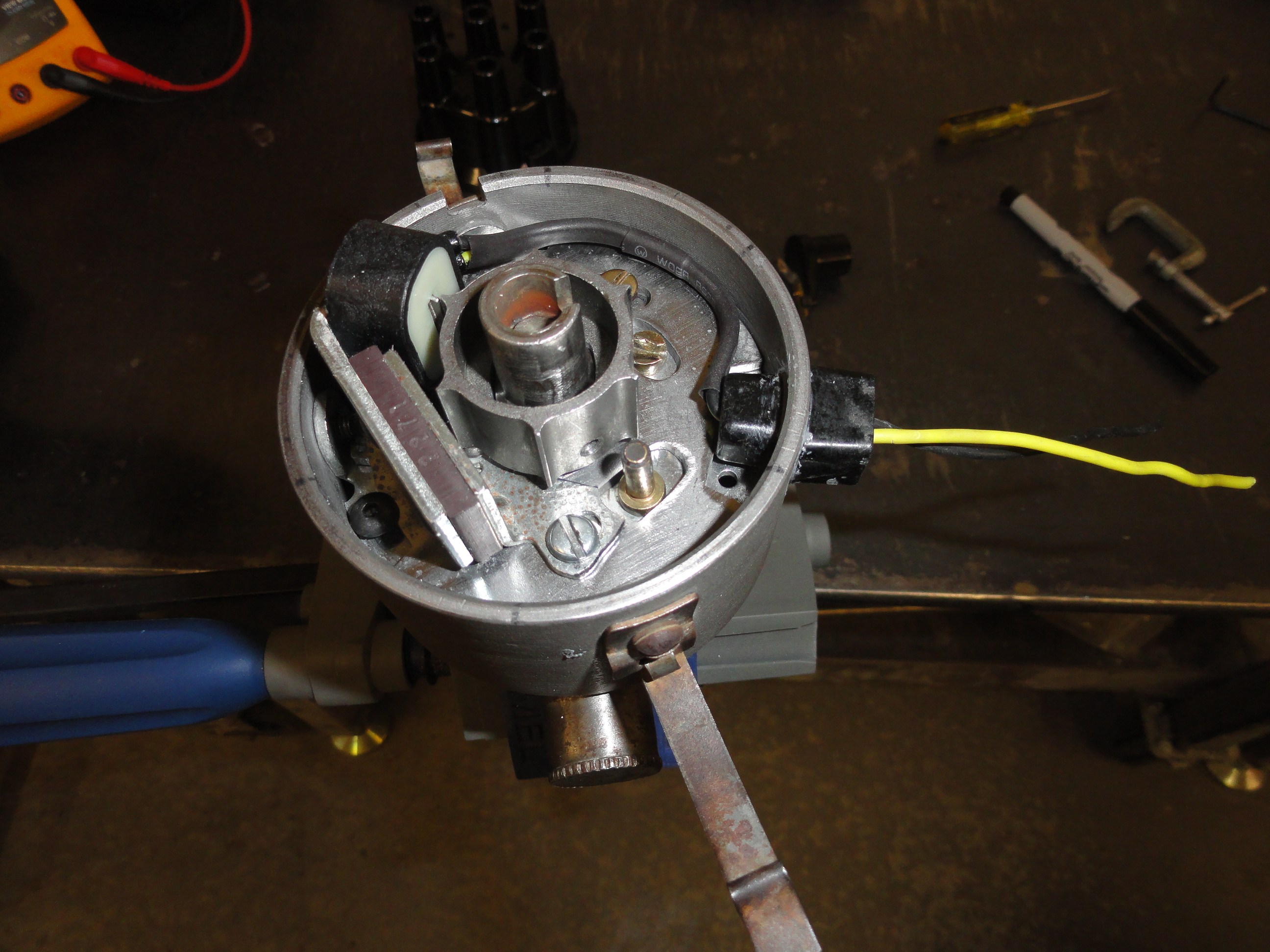
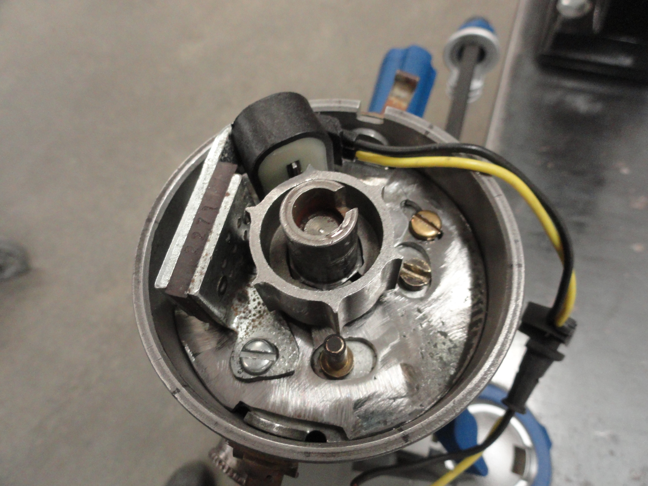
Before doing the tricky part, we need to know EXACTLY where number one spark plug is on the distributor cap. The preferred location is at about 5:00 with the black wire terminal facing away from the engine as shown.
Thing is, we are talking about electronic phasing here so we need to be very precise and without cutting a hole in your distributor cap so you can see. We will accomplish this with a multimeter set to ohms in beep mode. (So it beeps at us when it hits the sweet spot).
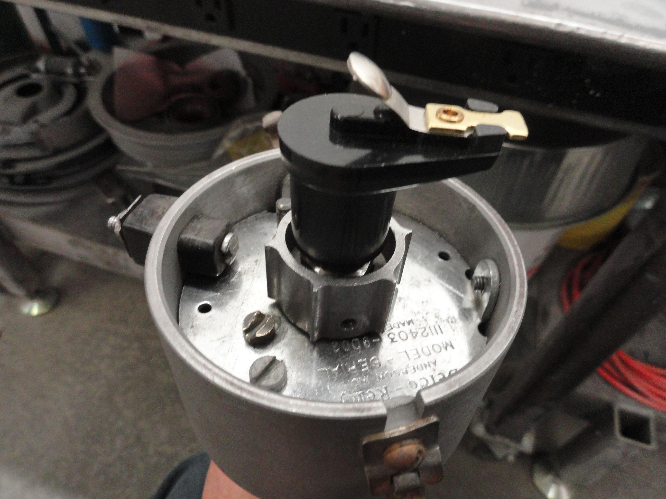
Remove your distributor, points and condenser if you haven't already and put it firmly in a vise so that it's allowed to turn through all
360 degrees. Install the rotor in the proper place and install the distributor cap. It only goes on properly one way because the cap is
keyed. Put one lead on the center hole on top of the distributor (coil input) and the other lead on the 5:00 hole as shown.
Since the cap wasn't designed for residual voltage, you will need to push up on the distributor shaft to get your reading. It will only
beep at you in one position through the entire 360 degrees and it's a very narrow band, probably one degree. This puts the rotor at exactly
#1 firing position. VERY carefully remove the cap making sure not to disturb exactly where the rotor is located. Critical issue that you
don't bump the distributor or move that rotor in any way.
Notice when removing the cap that the rotor and the reluctor lobes do not exactly line up. Using a straight edge, mark each lobe on the top rim of the distributor with a Sharpie so it doesn't go away easily. I just used a straight edge to transfer the lines over as shown. Fact is, we really don't care where #1 is located but that all the lobes are located for firing. The distributor will only fire when the rotor is under the caps plug wires.
Remember the more precise you do this, the more likely your phasing is set correctly the first time. This procedure puts the lobes within a few degrees so our reluctor pickup can adjust that far. We are shooting for approx. 5 degrees of adjustment for the next step. (1 degree on right side of center, 4 on the left). This is because the distributor rotates clockwise and most of your adjustment will need to be to advance.
The Reluctor Pickup assembly for this is made to drop into a 72'-85' mopar slant 6 so we can't use the plate that it came with. I found nothing redeeming about this plate so I removed it and started designing a plate for our Delco Distributor. Do not just willy nilly remove the plate! Follow the procedures coming to do that. Set the assembly aside for now. All we have to do now is re-design the pickup plate so that the pickup sensor is directly across from any of the lobes. Since we designed this thing to fit directionally so that each lobe also corresponds to each reluctor bump we will just refer to them as lobes from now on.
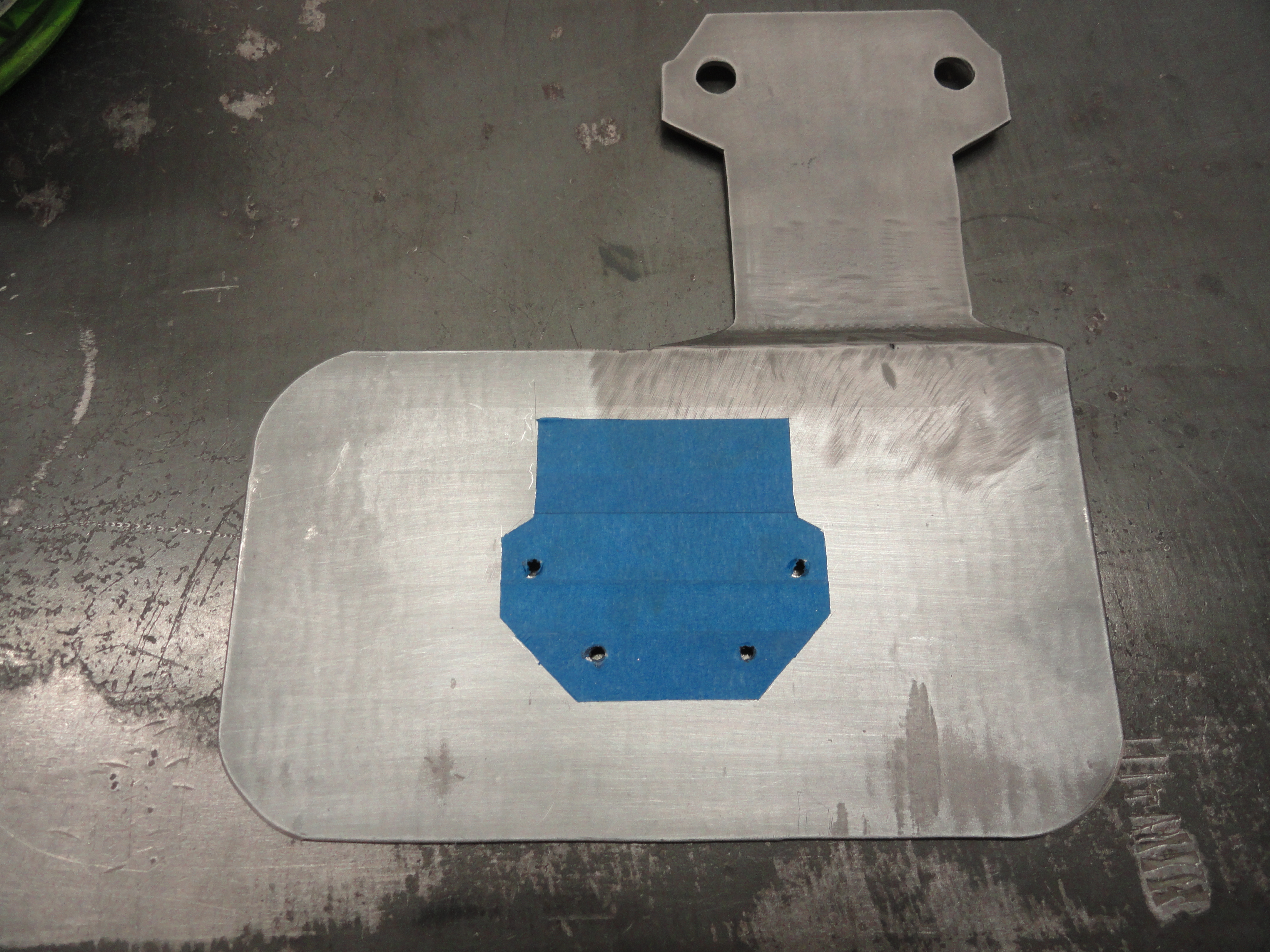
Now we will need about a 14 gauge metal plate that very cleanly accomplishes the following:
I experimented with three designs before I felt I got it right. The first was the one on the the left. The crescent shape proved to be too unstable for me. We are talking about two adjustments here and to do it cleanly you need nice smooth circular rotation, Although that concept would work, it's not any fun to adjust when the phase adjustment is interfering with the gap adjustment. Altho the one on the right is much more work, in the end it proved to be much smoother. After a great deal of playing around with this, the final design looks something like the one to the right.

I won't go into step by step on how to make that because in this case pictures and the linked template below will give you everything you need.
Be sure to print at 100%. Most printers do not by default. Yours will come out better than the ones shown since I had to figure out all the geometry
myself which for me required adding weld, taking it away, etc, etc. Funny thing, turns out a roll of blue 3M brand masking tape has the exact same
inside diameter as the distributor!(3")
When you are through, the 14 gauge metal plate should fit perfectly inside the distributor with no slop whatsoever. If there is enough interest, I
would like to get a bunch of these templates waterjet cut out of stainless steel so they are all perfect.
Next we need to mount the pickup assembly on the new plate. To remove the pickup assembly from its original plate, drill out the rivet using a #36 drill bit. Do not make this hole larger than #36! We will be tapping this hole and the new plate corresponding to this hole for a 6-32 screw. This method will take the place of the rivet quite nicely. We will Loc-Tite it in place later. Remove the hold down screw on the old plate and you should have just the pickup assembly free. We will re-use the hold-down screw because it is short enough to be flush with the bottom of the plate when it's mounted. The 6-32 rivet screw will need to be shortened to be flush with the bottom of the plate as well.
There is ZERO room for error in making this adapter plate because of the space we are trying to use. As it stands, using this new plate, I still had to grind a small ridge off of the Distributor Cap to get enough room. It's probably about .020 deep! Almost nothing, but it had to be done. It will have no adverse affect in any circumstance, so I didn't feel TOO bad about it. You will probably need to grind both of those bumps off just about the first 3/8" of the inside of the cap where the reluctor pickup bends out.

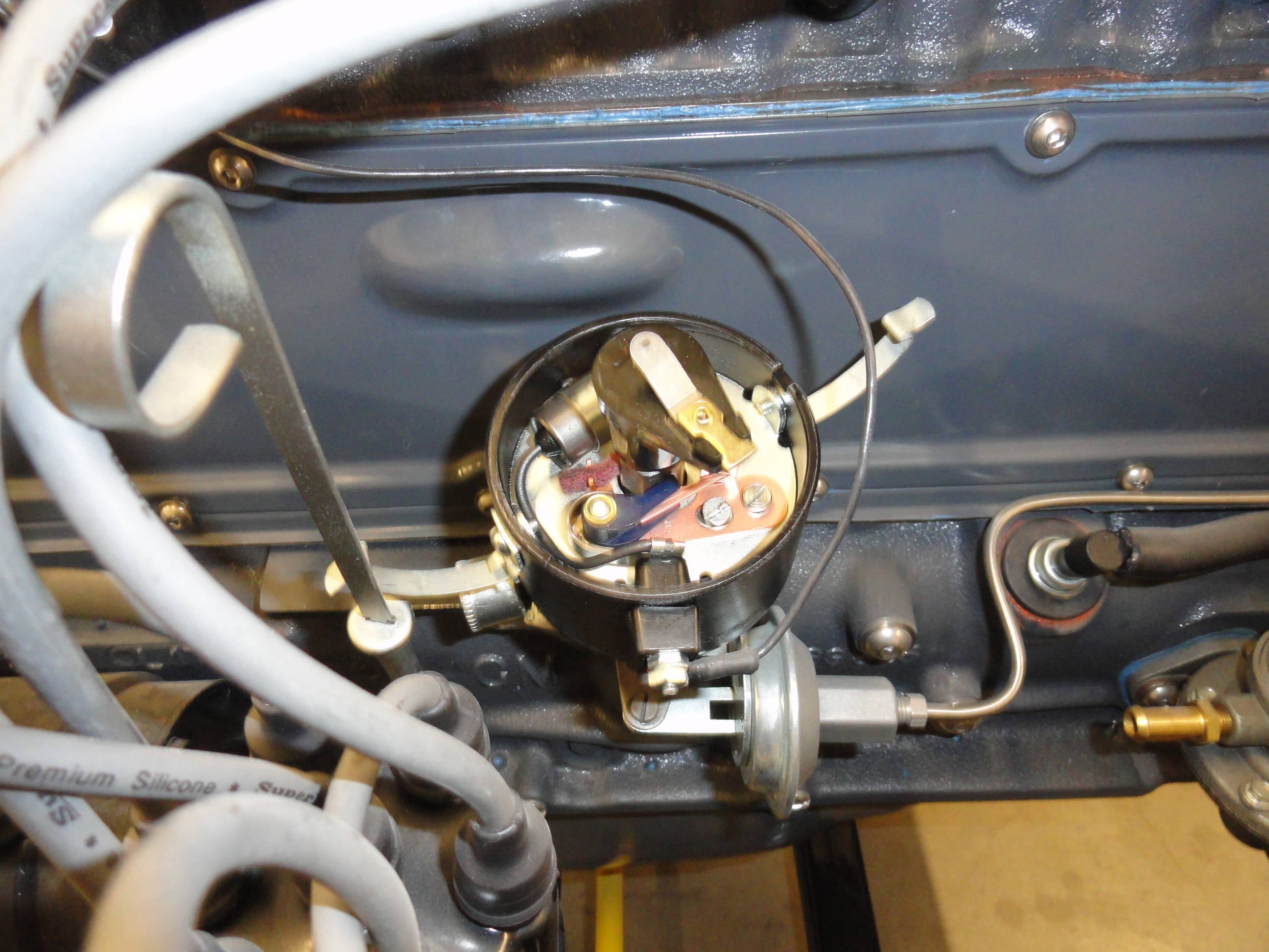
Once you have the adapter plate in place with the pickup assembly, install it and make sure the magnetic pickup is lined up exactly with the marks you made on the top rim of the distributor. If you rotate the plate, you have 2.5 degrees on one side of the mark, and 2.5 on the other side. Install the reluctor and set the gap to .007. Now you see how tight it is!
Rotate the reluctor through all six lobes to make sure it maintains .007 or so through all of them. If you need a little adjustment, very little, you can loosen the set screws on the reluctor and wiggle it a bit for ultra fine tuning. Rotate the distributor and make sure there is no noise coming from any of this. Your reluctor may be bottomed out scraping on the new plate. No problem, just loosen the set screws and pull it up a bit. Move the reluctor up just a bit higher than the pickups sensor. You have plenty of room that it will not interfere with the rotor.

So we have established the Distributor cap and rotor fit nicely and the distributor turns quietly. The gap is set to .007 and the lobes are indexed to the pickup assembly. It should work right? I don't know yet because there are still a few loose ends.
One of the conundrums in dealing with this project is trying to keep it looking stock. But what to do with the two wires coming out of the distributor? That black plastic that sticks out with the single wire attached helped give the stock look, the stock look! And, worse, it's right where you can see it when it's mounted.
The best I can come up with on short notice is, we Permatex the black plastic pieces back in the hole and to each other. The distributor works as advertised for points if you keep the screw assembly part in your toolbox, and we CAN get two wires out to the outside this way. If the Permatex ever came loose, you can't lose your parts because there are wires through them. This will enable you to get to the bottom end of your distributor without alot of extra problems. I did some further research and if you were to use a long piece of black shrink tubing around the two wires, you would have a hard time noticing at all. I was able to obtain a few schematics of the system. This really makes it clearer and should help in understanding the whole system.
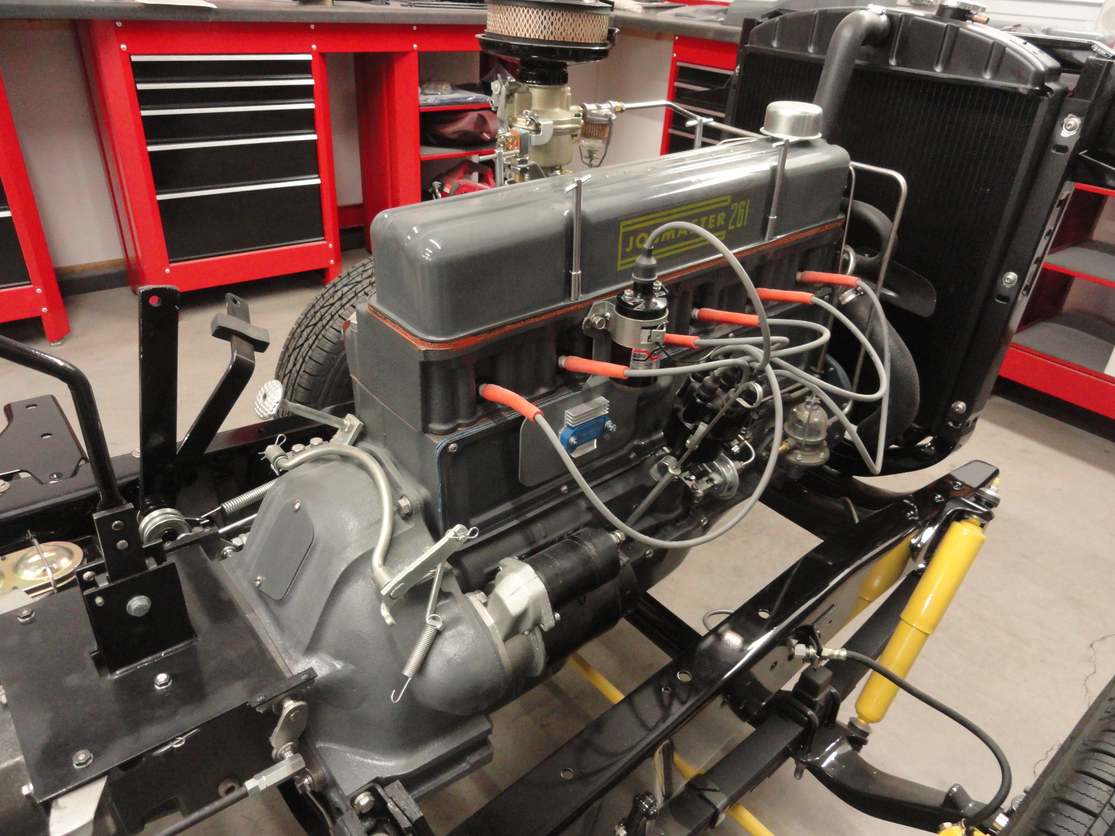
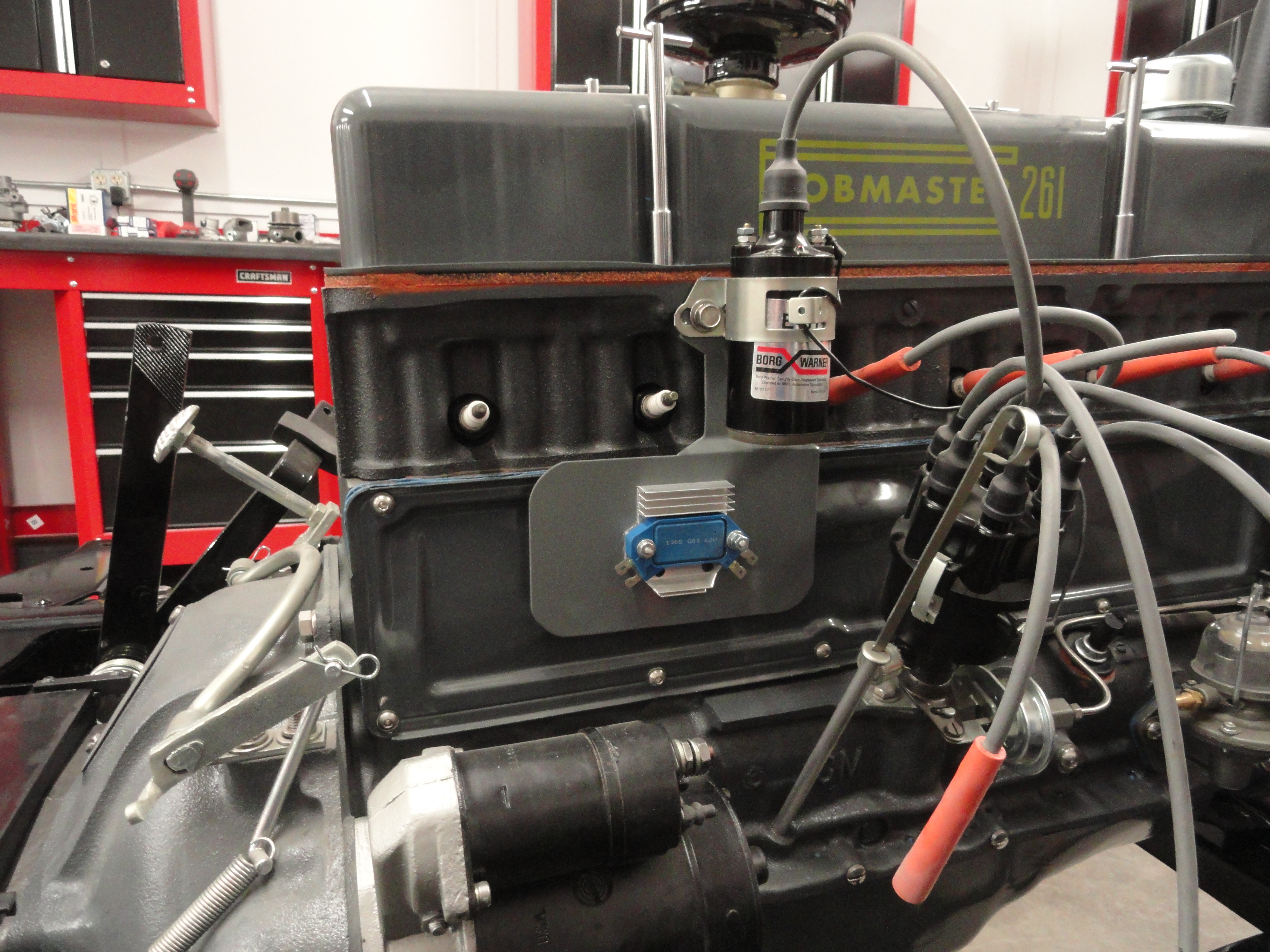
Another modification that I felt necessary has to do with WHERE do we put the HEI Module and Heat Sink? We want it close to the coil and dizzy so everything is located in the same place if possible. After spending hours thinking about it, I devised a bracket that will place the unit exactly where it should go (in my opinion). This is unused real estate, has air flow across the module as well as behind it, and it's the right size if you choose to cover the module and heat sink with a stripped out Delco-Remy Regulator Box. You could even chop the box a bit to make it look flatter, just like it belongs there.

The plate is made out of 11 gauge steel and the dimensions started at 7" x 8". The width at the widest point of the coil bolt pattern is 3-1/2". The first bend is at 3-3/4" down from the top, while the second bend is at exactly 4 inches. That is a very hard bend to make with rudimentary shop tools. I just cut that part off at 4", then measured 1/4" up, then used my vise to make one bend angled at about 45 degrees. I then just welded it back up and did the whole grinding and dressing thing. The coil mounting holes are 2-3/8" between them center to center. I made 3/4" relief cuts to make it easy to get the spark plugs out, then rounded the corners with a band saw. The top profile is the very same profile as the coil bracket.

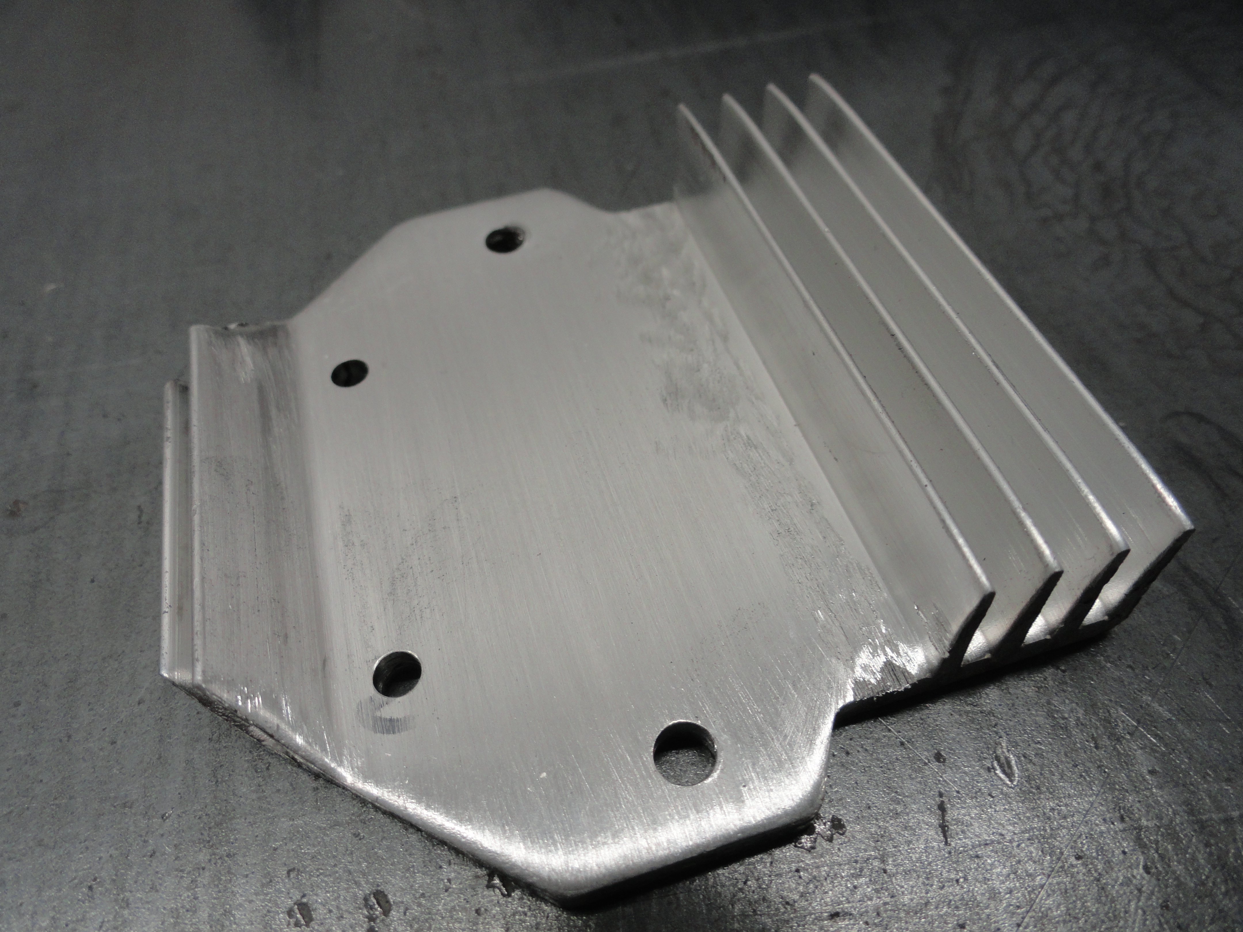
Cut the first fin off of the HEI Heat Sink to mount it the way I did. Grind it completely flat. Place the Heat Sink in the very center of the plate and mark the 4 holes. The bottom 2 will be drilled with a #29 drill bit, the top 2 with a number 36. Tap the bottom two holes with a 6-32 tap, the top holes with an 8-32. The 6-32 screws will go in on the front of the unit, the 8-32's will go in the back. This is not just a very secure way to mount this unit, it also ensures a very solid ground.
Tape the area and around where the heat sink will go before painting. We want that heat sink to set on bare metal. Bolt the heat sink to the adapter plate and using a sharp X-acto Knife, cut very closely around the heat sink. Remove the excess tape, then primer and paint the plate your choice of color. Warning! When removing the tape, first run that X-acto Knife around the tape so you don't peel away your precious paint!

The 8-32 screws come in from the back. Get long screws because you want to ensure you have enough length. Both of them will not be the same length. One will hold down the module with just a washer and nut, the other side needs washer, nut, washer, nut. This is to give us the length we need to add a ground wire if necessary. I chose the one on the right to be the longest but it doesn't matter. Using a multimeter when you are done to ensure you have very solid ground from anywhere on the engine or frame of the truck to that ground screw is a really good idea.
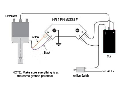
Schematic One is a generic 4 Pin HEI module setup, just like what we are doing.
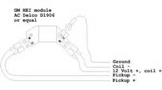
Schematic Two is the actual GM HEI module which is the same as ours and confirms what Schematic One gives us. I always feel better when I have
two independent sources especially when wiring is concerned.
Our Reluctor Pickup system uses a Yellow wire and a Black wire. So Pickup (+) would be yellow and Pickup (-) would be black. It matters which is
which as doing it backwards can change the phase as much as 30 degrees!
The stock GM coil from 1955-1959 was a 6 volt coil. If you ohm across the two terminals of the coil it is approx. 1.5 ohms. If you ohm from the other side of the ignition resistor on the firewall to the -minus terminal on the coil, you should get about 3.5 ohms. In other words, GM ignition resistors are 2 ohms. If you have a Resistor Coil and no ignition resistor on your firewall, measuring across the two terminals will get you about 4 ohms.
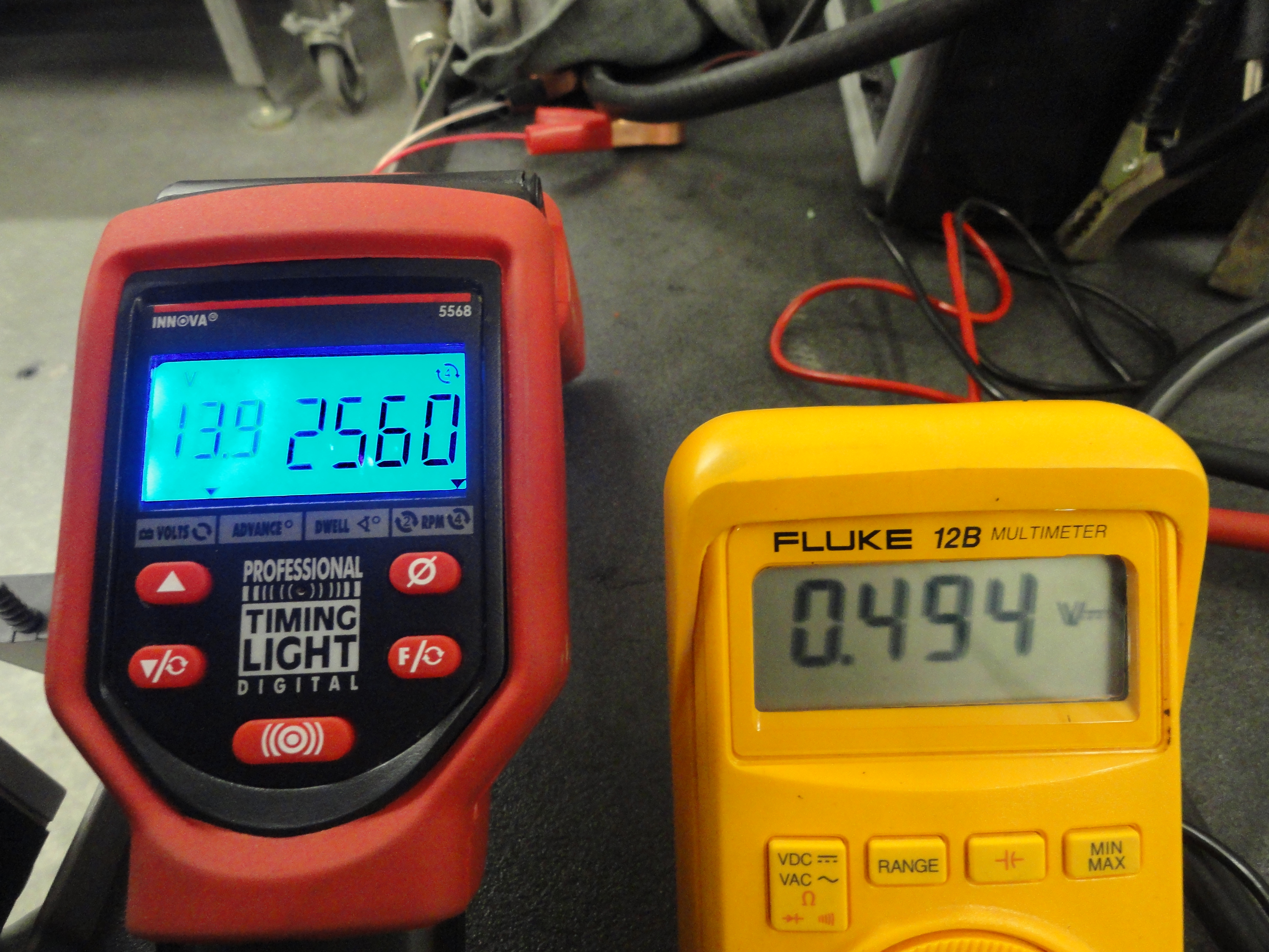
The breakdown for the stock system is about as follows: With charging system running about 13.8 volts, and the current in the circuit at about 3.94 amps, once the charge hits the ignition resistor on the firewall, the voltage is cut down to 7 volts. Once it has gone through the coil, there is 5.94 volts at the points. If you have the resistor coil it's less. Very balanced system, but not what we are looking for with an HEI system.
We care because the ignition resistor and 1.5 ohm Coil keeps the current limited to make our stock parts last longer. But now we have a more modern system with its own current limiting circuit. Our HEI system limits the current to between 5.5 and 5.8 amps. Also, our HEI system likes to run at as close to 12 volts as possible. These two facts make the old coil obsolete.
It also means the idea of bypassing the ignition resistor during cranking, and all that was sacred for the points system is now a detriment. Your new HEI system will not require the firewall ignition resistor. This can be bypassed with a nice new piece of 14 gauge wire jumpered across the resistor when installation time comes.
Our new HEI technology craves 12 full volts during regular operation. The HEI module has its own current limiting (5.5-5.8 amps), so we aren't concerned with excessive current. We want full voltage, so the coil you want is the one with the least PRIMARY ohm value. But the problem with using an ohm value too low is that your HEI module is dissipating more current thus gets hotter. Lets explore what's happening..
Ohms Law Calculator
Not including normal voltage/current loss through wires which is expressed as resistance:
13.8v (max) Input w/1.5 ohm stock coil with 2 ohm Ballast Resistor - 3.94 amps
13.8v (max) Input w/4 ohm replacement resistor coil - 3.45 amps
Those are the choices usually associated with a stock points system. Now let's look at lower ohm values that work best for HEI. (Based on 13.8v max input.)
We are interested in MAX voltage input because we are determining wire sizes and want to err on the side of caution.
.7 ohm(R) coil - 19.71 amps (I)
.6 ohm(R) coil - 23 amps (I)
.35 ohm(R) coil - 39.42 amps (I)
As you can see, there is a point where it gets pretty scary! Since the HEI module we are using for this limits the current to between 5.5 and 5.8 amps, we are not concerned about amperage to a point. Since the .35 ohm coil would obviously be the closest to our goal, you might think that's a good choice. The reason it is not, has to do with the HEI modules heat sink dissipation rate. It would just get too hot and fail prematurely. In the end, the sweet spot from a mathematical perspective appears to be a 12 volt coil between .6 and .7 ohms. One of the main reasons we are doing this upgrade is to get a much hotter, wider spark that allows us to run .045 point gaps so that we can ignite leaner mixtures and greatly improve engine performance. The new coil and balanced wiring system will make a big difference.
NOTE: When you go to purchase a stock coil for your 1955-1959 (or AD with 12v system) the parts stores have them listed as 12 volt coils. A prominent "12V" is even stamped on the side of the coil. This was done because there were so many purchasers that insisted on a 12v coil, the company relabeled them to 12V to eliminate argument. Vintage coils are not voltage rated. A 6v coil from the 40's or early 50's will make your 12v stock system run just fine. This can be proven mathematically. The 6 volt system didn't have a 2 ohm ignition resistor, so the numbers come out exactly the same! After HEI was invented, they DID start rating coils by voltage as well as ohms. I am saying all this because when you go to get your 12v coil, don't end up with the same coil you already have!
This link provides an example of a suitable coil for our project. There are many more choices including square coils but most people like the round can style for this vintage. I found this one at Summit Racing.
The gauge of wiring in your vehicle was fine for the 9 volts and 4 amps or so that it was designed for. But now, we want to run 6 amps through those wires. This is why GM beefed up the ignition wires on HEI systems. You want to prepare for more current than your system is used to. New wiring is probably okay, but old wiring could cause a fire, so please look hard at your wiring. My recommendation is to go with 14 gauge wire clear through the ignition system just to be safe.
If your plan is to keep a points distributor as a backup, just keep the ignition resistor on your firewall and keep the stock coil then remove the jumper from the ballast resistor.
Hooking it up seems pretty straightforward other than that. Take the wiring slow and check and double check to make sure everything is wired correctly.

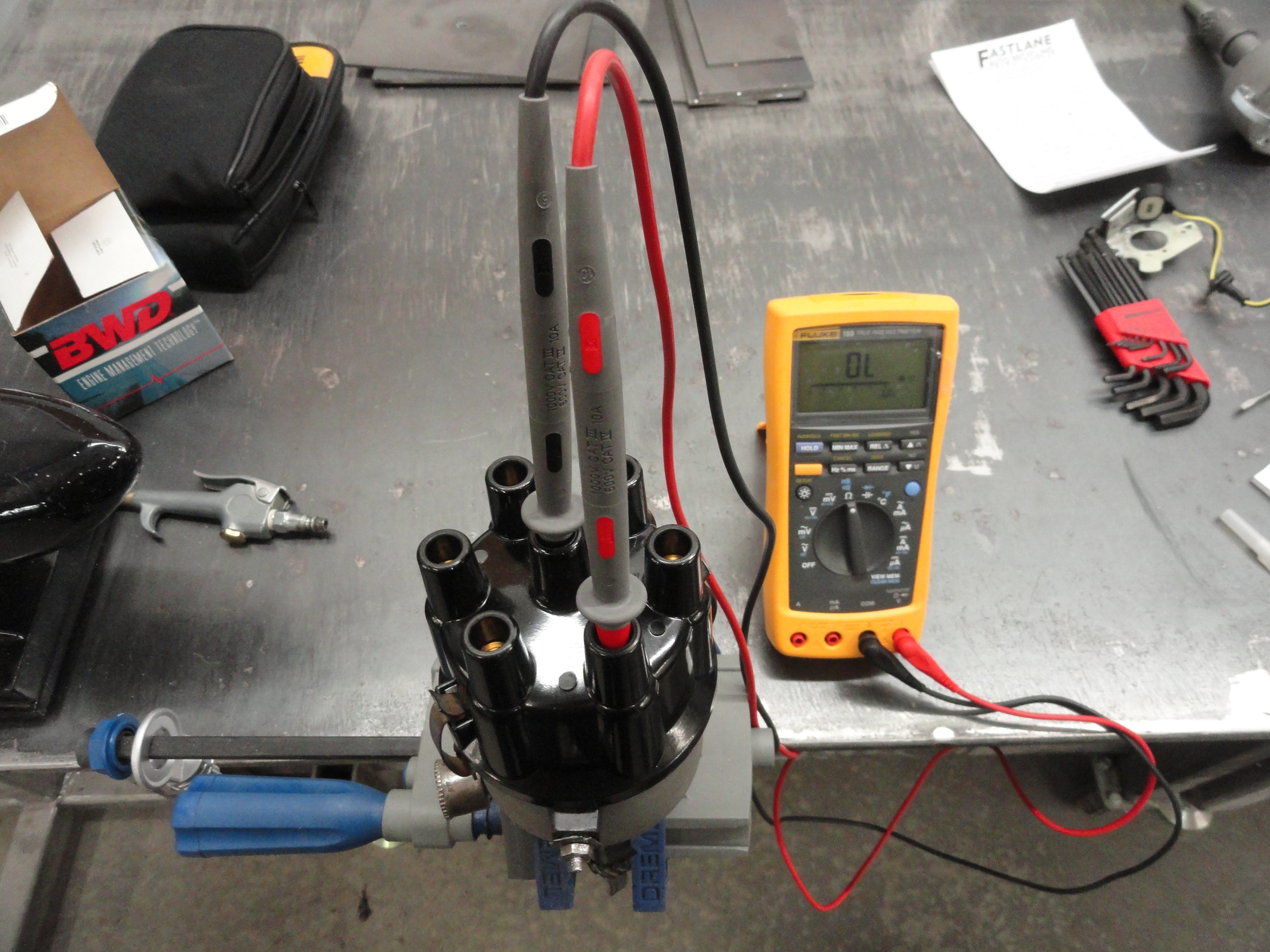
The reluctor and reluctor pickup that you have replaced your points with is merely a trigger to let the GM HEI Module know when it needs to fire the coil. It needs a minimum of 9 volts peak AC to trigger the Module. If you have your reluctor setup gapped properly (.007 or so) you will easily get 14 volts peak AC or more. Each time a reluctor lobe aligns with the reluctor pickup it causes this voltage spike which is your trigger for the GM Module. You see, this is a very simple system and most of the work has been done for us as far as getting its operation down to a science. The reluctor lobes are spaced exactly as they need to be, the reluctor pickup is monitoring the reluctor and spiking at just the right moment. This is really an ingenious way of eliminating Points. No parts coming into contact with each other, and the power for the trigger is provided by a magnet. Pics left and right are with the motor running. (VERY smoothly!)
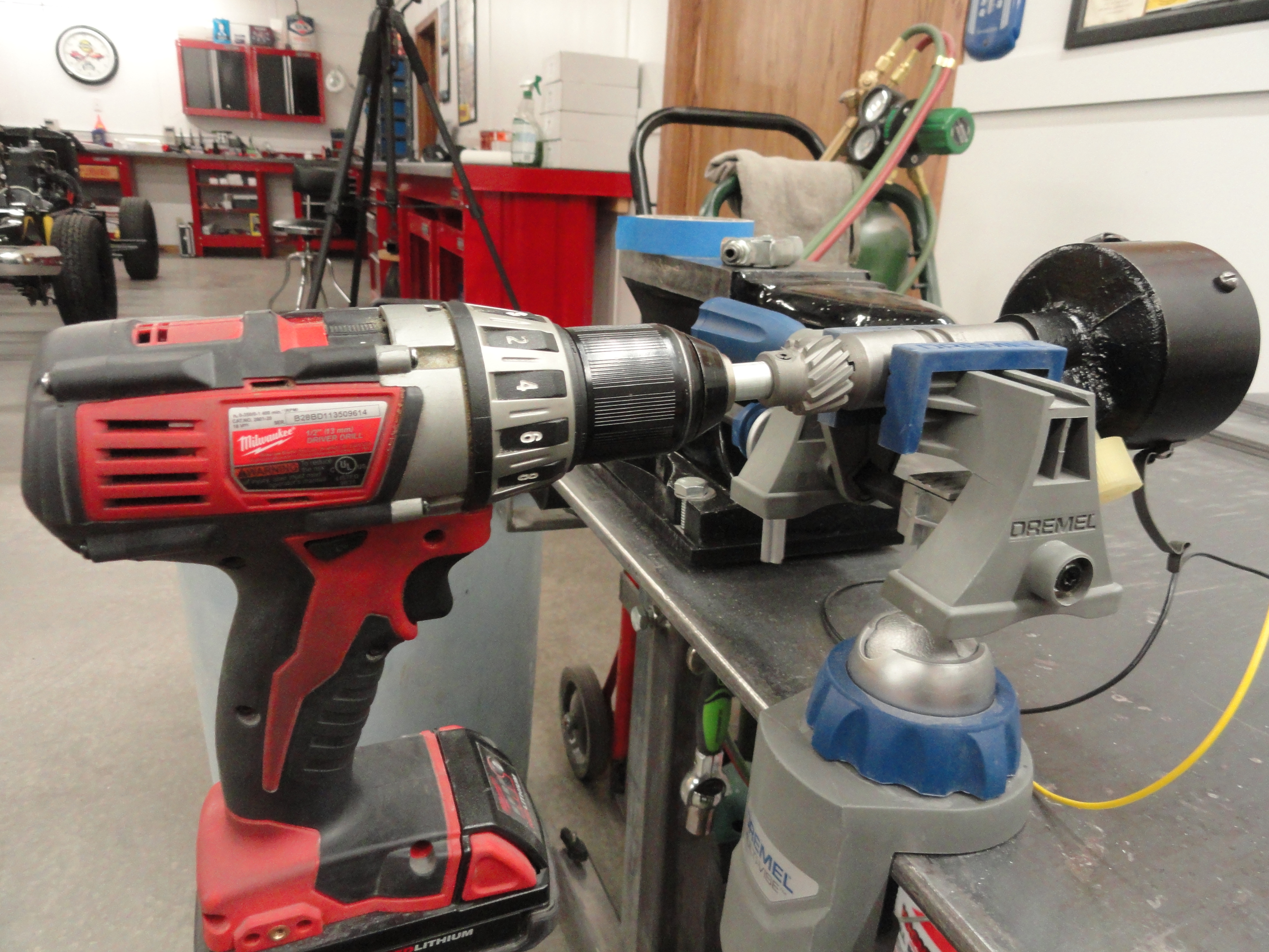
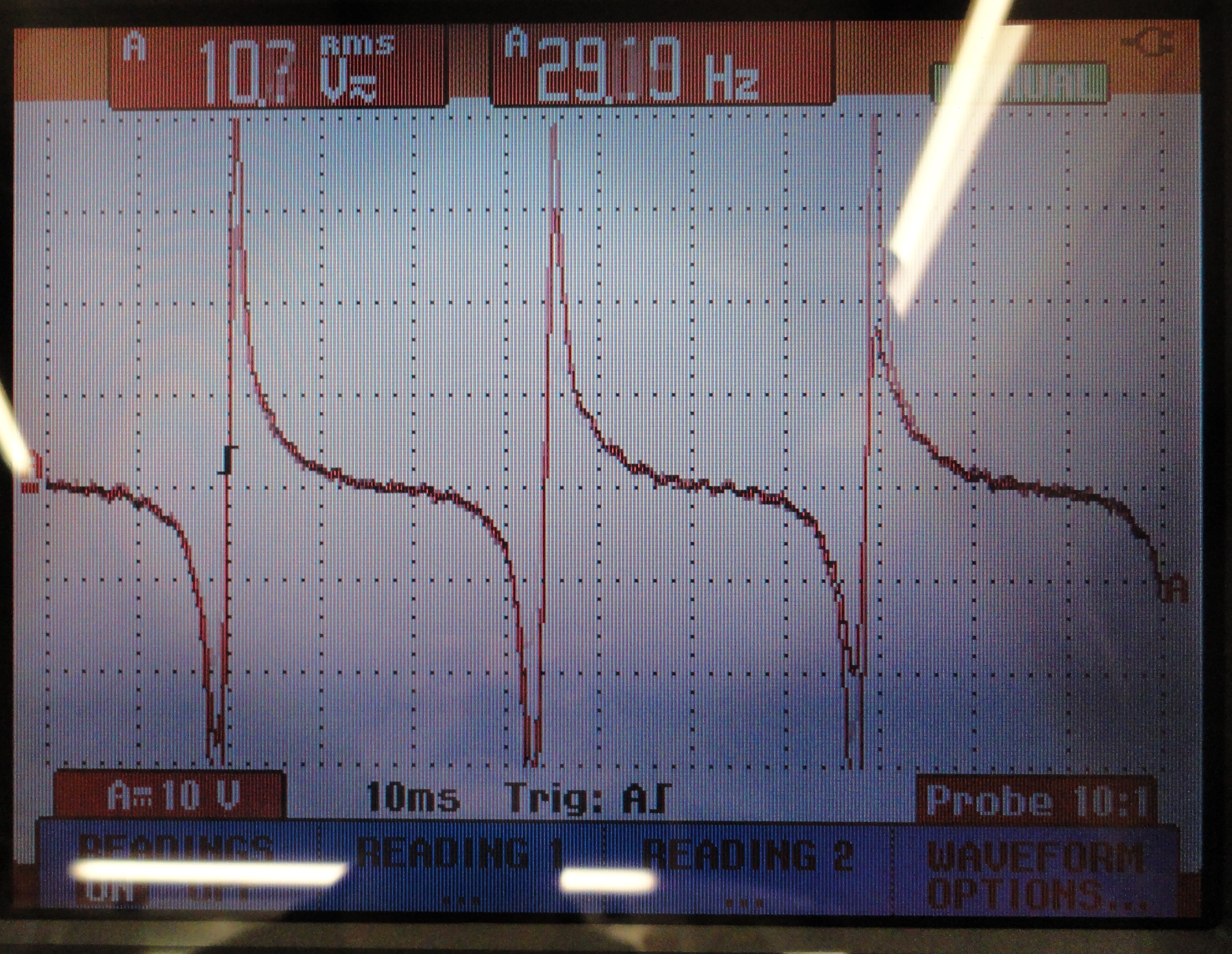
Running the distributor in a drill is my poor mans Distributor Machine. It doesn't tell me nearly enough, but when I slow the drill down I can actually watch each lobe's trigger in real time on the O'Scope. I noticed that most of the distributors we have out there have an ever so slight wobble to them. This explains why some triggers are of lower amplitude than others. The gap is slightly different. This is okay as long as the voltage is above 9 volts. If you do not have an O'Scope, don't worry, if you gap it properly, and if you connected it according to the wiring diagram, it will work perfect the first time. If you do have access to one, use your x1 Probe and set the Scope for 10v/10ms. There is no need to worry about a shock hazard since the current is very low. The pic right is with the drill motor turning. As you can see other than a little noise introduced by the motor, there is very little difference between the two methods.


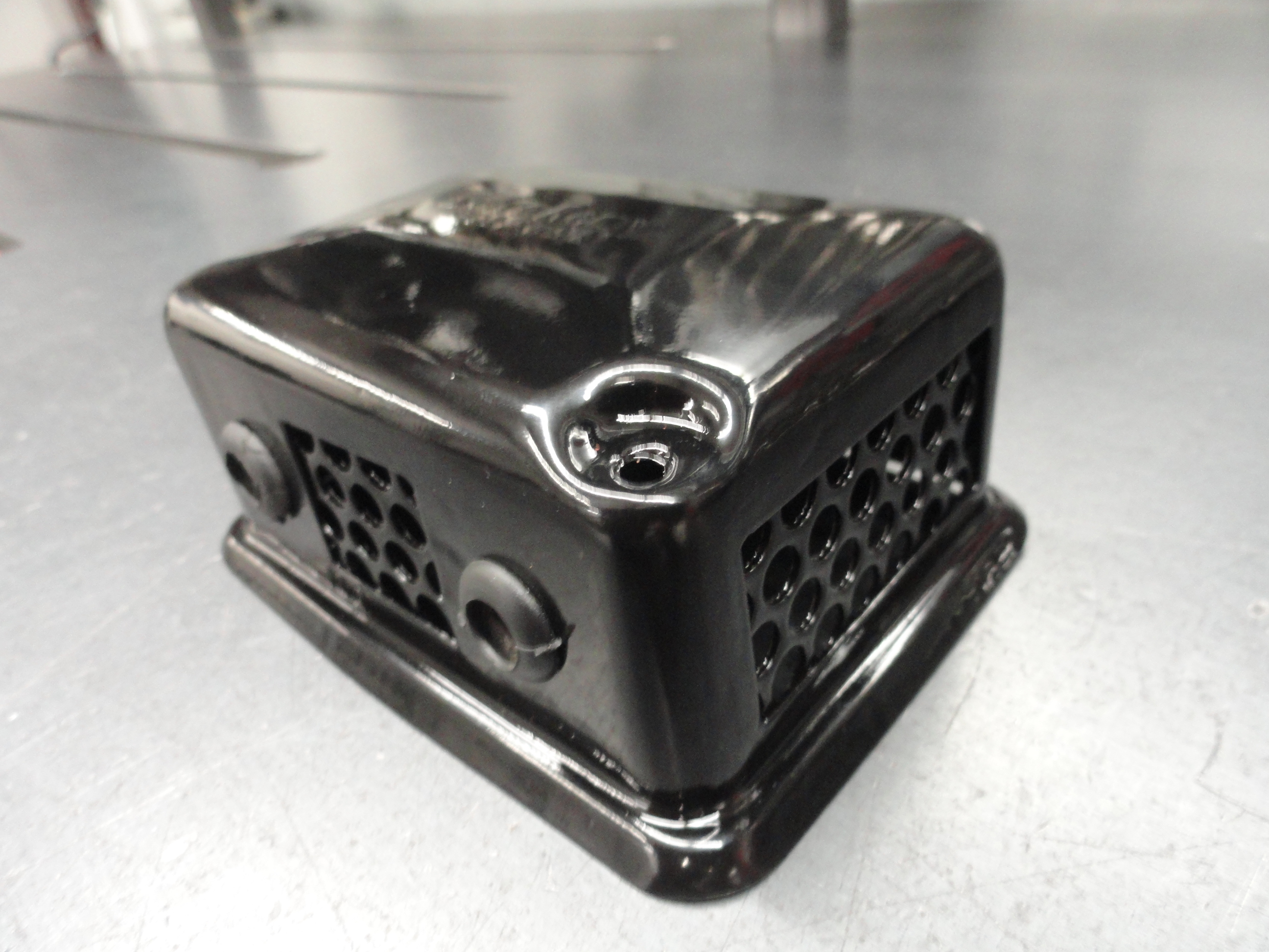
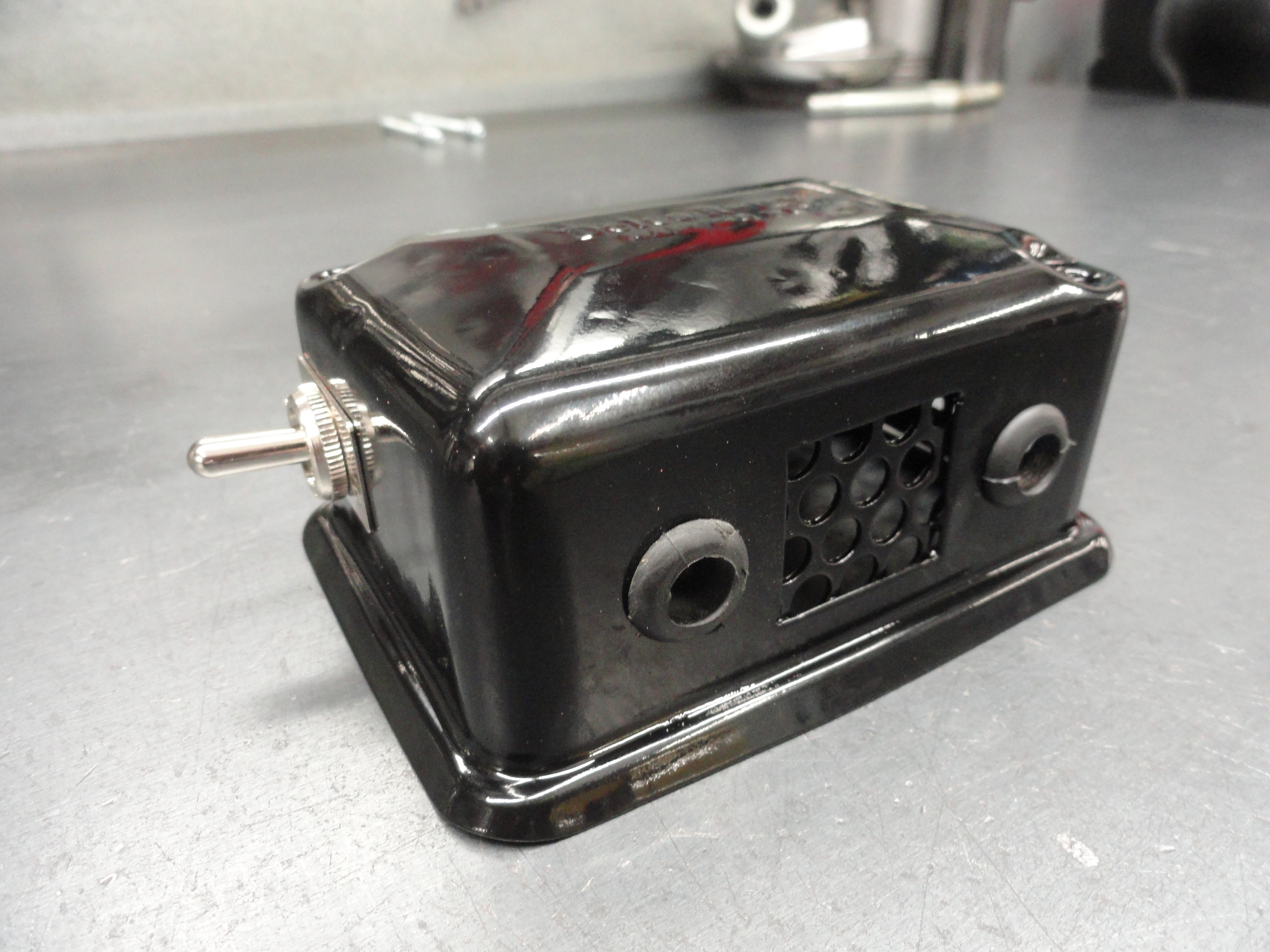
These two pics left and right are offered to show you what the two wires can look like coming out of the Distributor. The idea is to NOT draw attention to the fact that the internals in the Distributor have been modified. So, aesthetically, it looks pretty much like one black wire coming out of the Distributor. If that HEI Module's bracket and looks is something that you just can't stand, you can hide it anywhere you want, even under the dash. I just feel the shorter the wires, the better. Since this is a test engine it also has a ballast resistor mounted, but if that wasn't there, you could put the cover of a external regulator over it and it would look pretty cool I think. While you are at it, get a regulator cover with the Delco-Remy script on it! Put a coil shutoff switch on there while you are at it!
A few measurements are necessary to get the wires set up correctly. I cut the reluctor pickup wires at about 1-3/4 inches from the pickup so I can add another 23 inches to it, and have the splices inside the Distributor. Splicing it there is safer in that it won't pull apart as easy as anywhere else. I always solder that connection and then put 5/32" heat shrink over those two splices. I then cut a piece of 1/4" heat shrink 2-3/4" long and slip that over the reluctor pickup as best I can and the wires to demarcate the inside wiring. I then thread the wires through the phenolic in the usual place to the outside. Once outside, I cut a piece of 1/4" heat shrink 2 inches less than the length of the remaining wire. You can get these nice long unbroken pieces in all sizes at Harbor Freight among other places. Lastly, I take about a 2 inch piece of 3/16" heat shrink and slip it over the end of the 1/4" near where you will add the spade connectors for extra support. Two red spade connectors and a good crimping finish the job. If you have a better idea, please share! I am always interested in improving these articles!
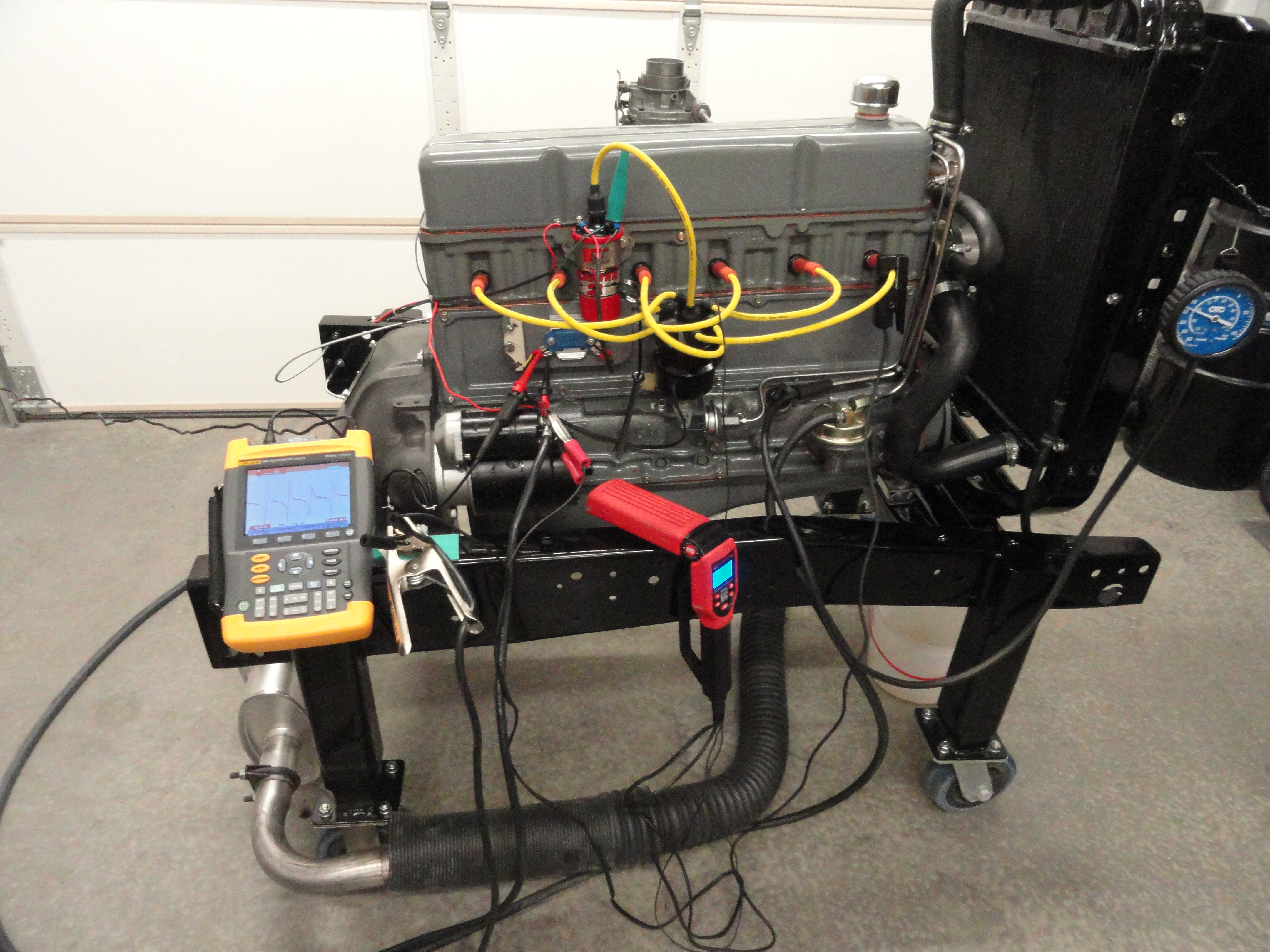
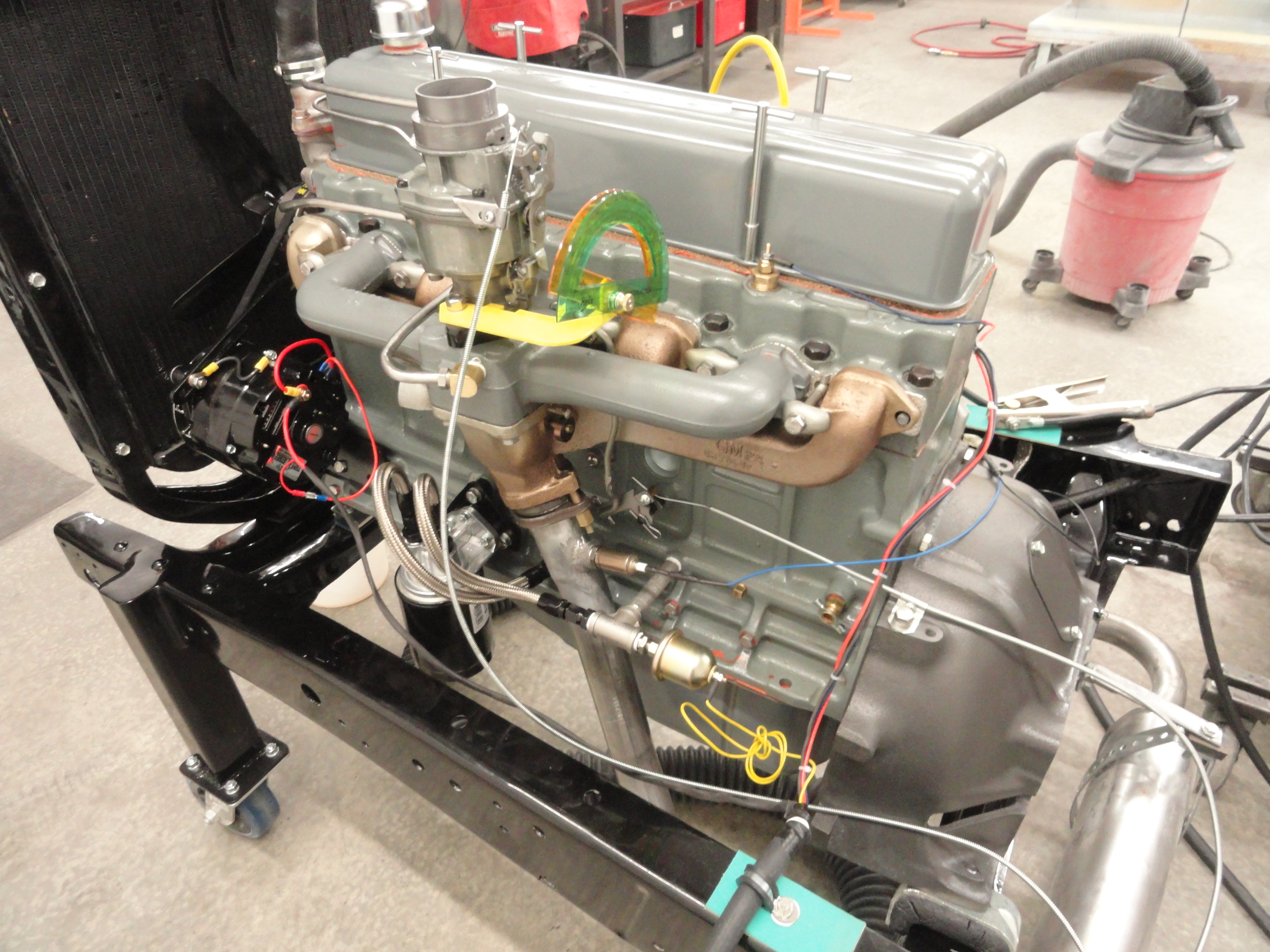
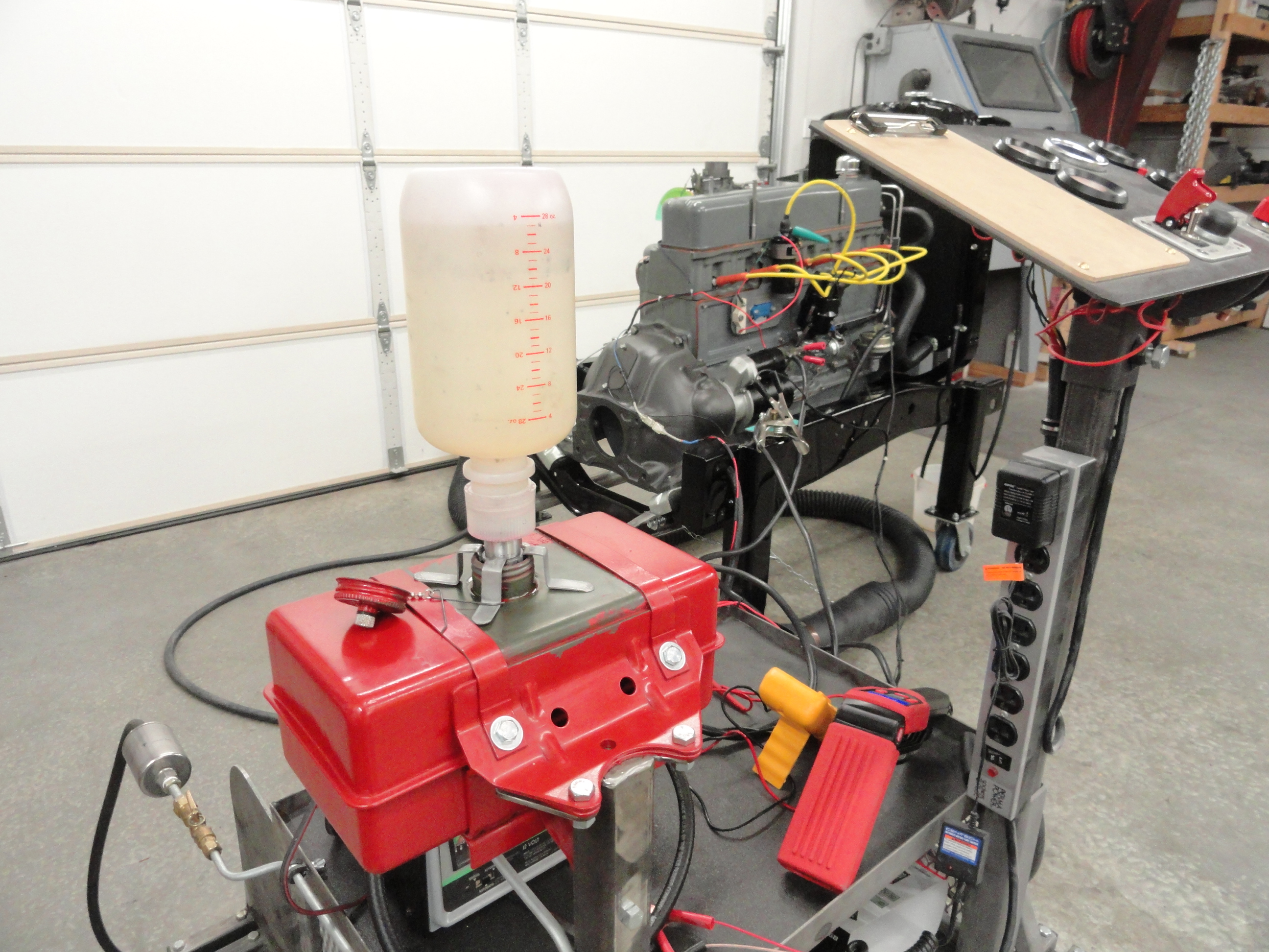
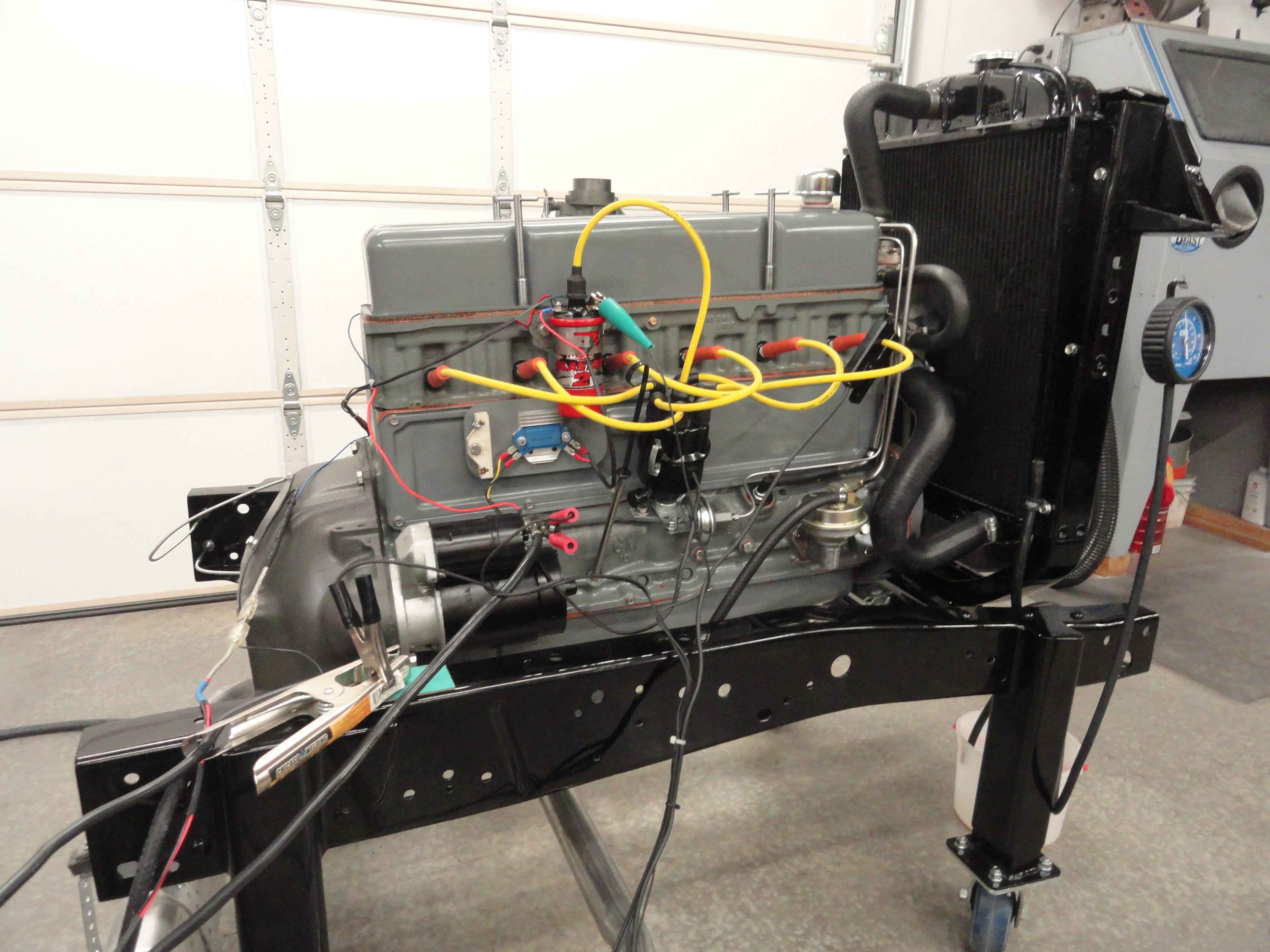
People want to know if the conversion to an HEI system impacts fuel mileage. I do not know so we are about to find out. I have limited capabilities as far as this idea goes, but we will make the very best of them! We will use our 1959 235 Test Engine as one of the main controls. Controls are implemented to ensure repeatability and to eliminate as many variables as possible. The idea is to be able to prove repeatability and get all of the anomalies out of the process.
This is only a laboratory test meaning we can prove consumption rate in laboratory conditions. With no Dyno and no load, road conditions will vary but the main findings will be the same. This is because all tests are conducted under the exact same conditions. There is no favor given to one kind of ignition system over another.
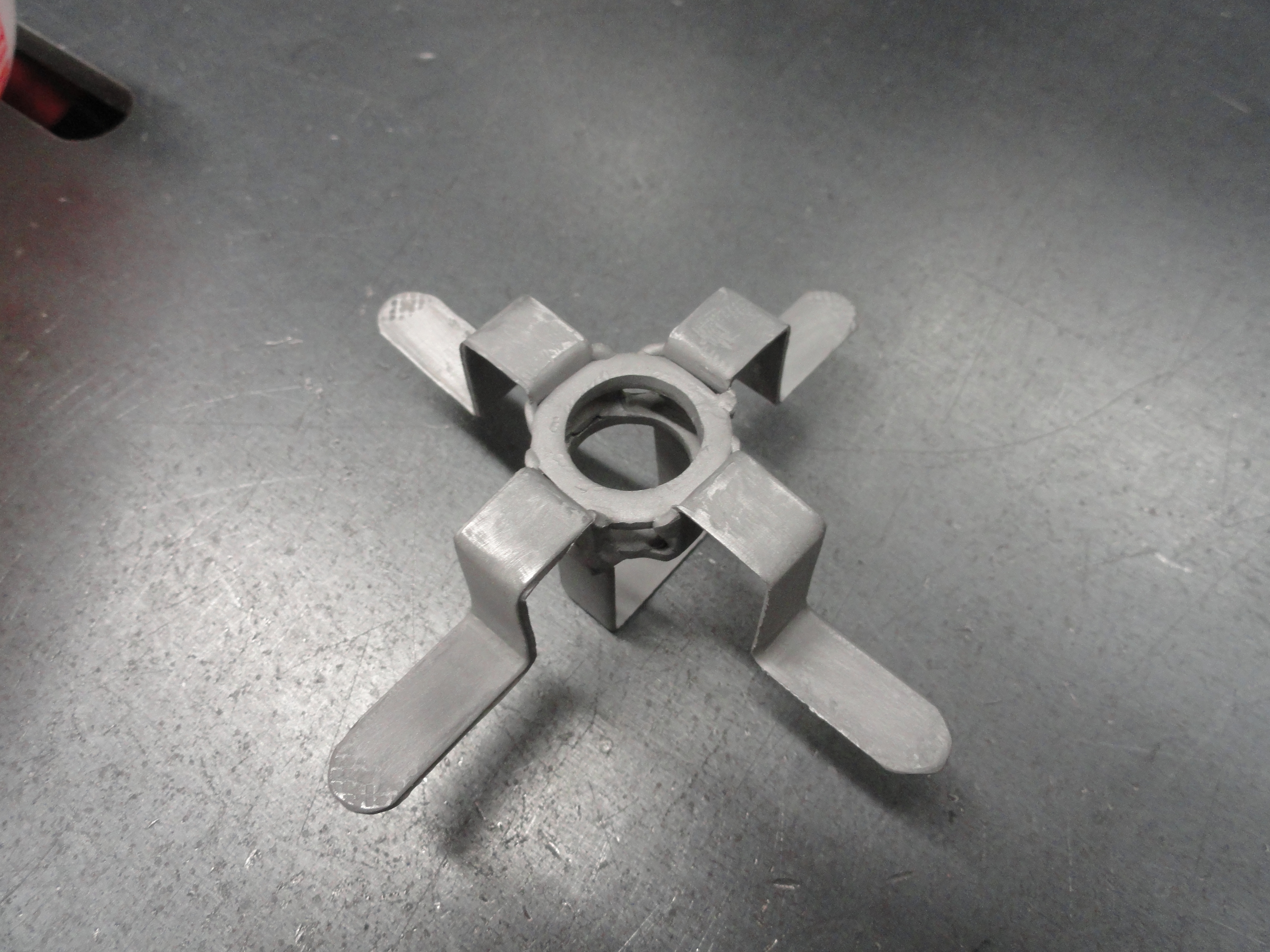
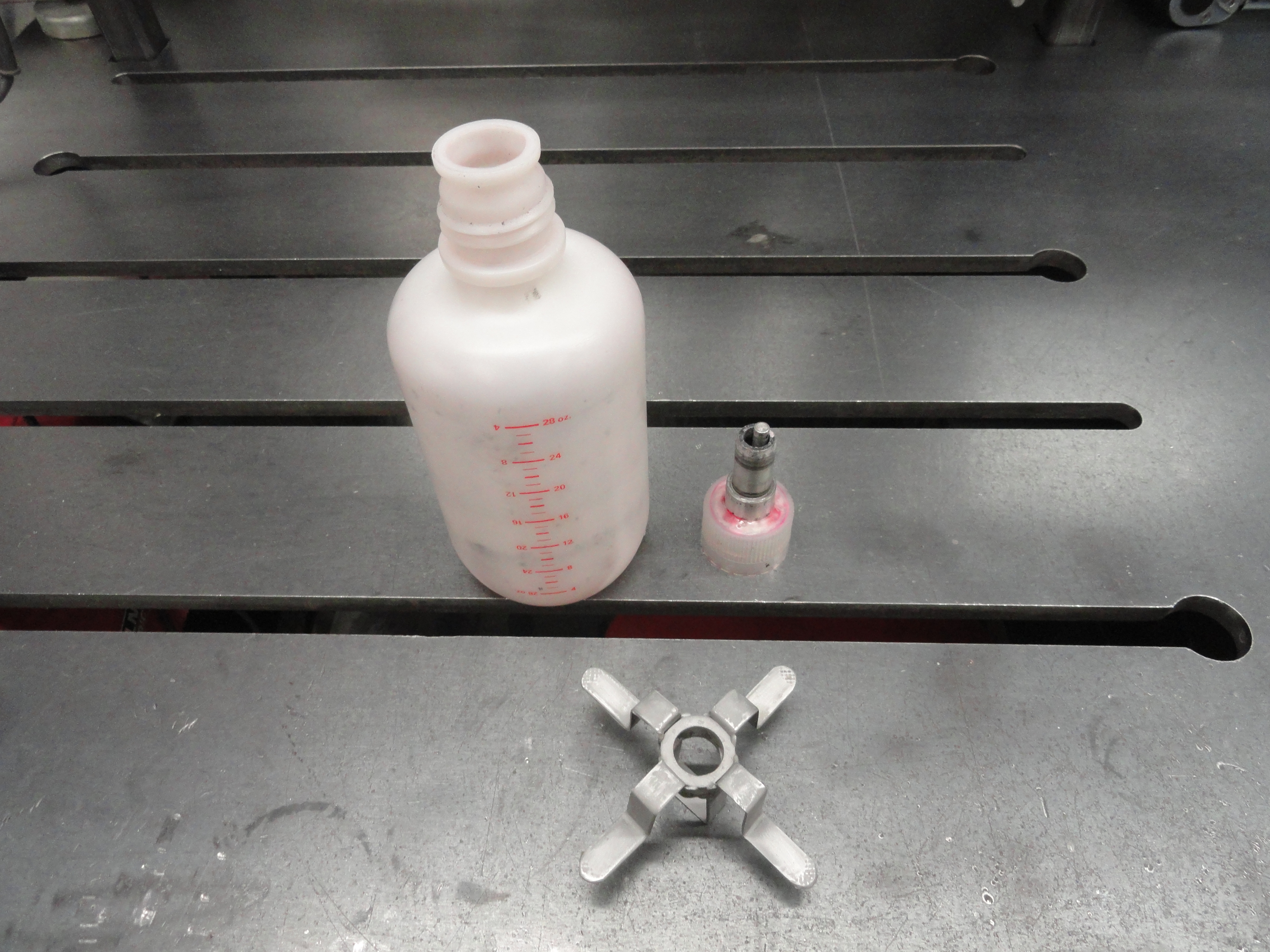
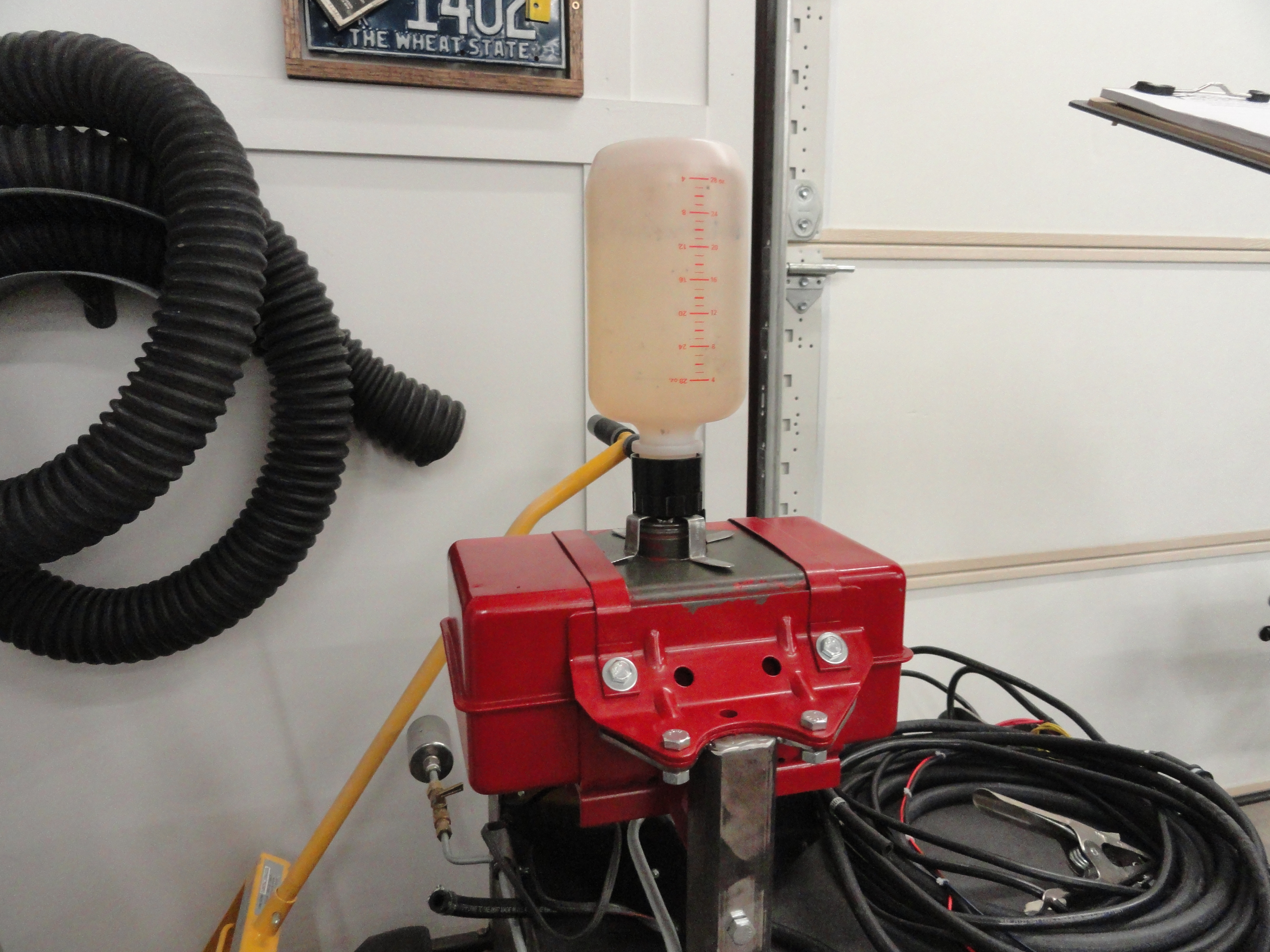
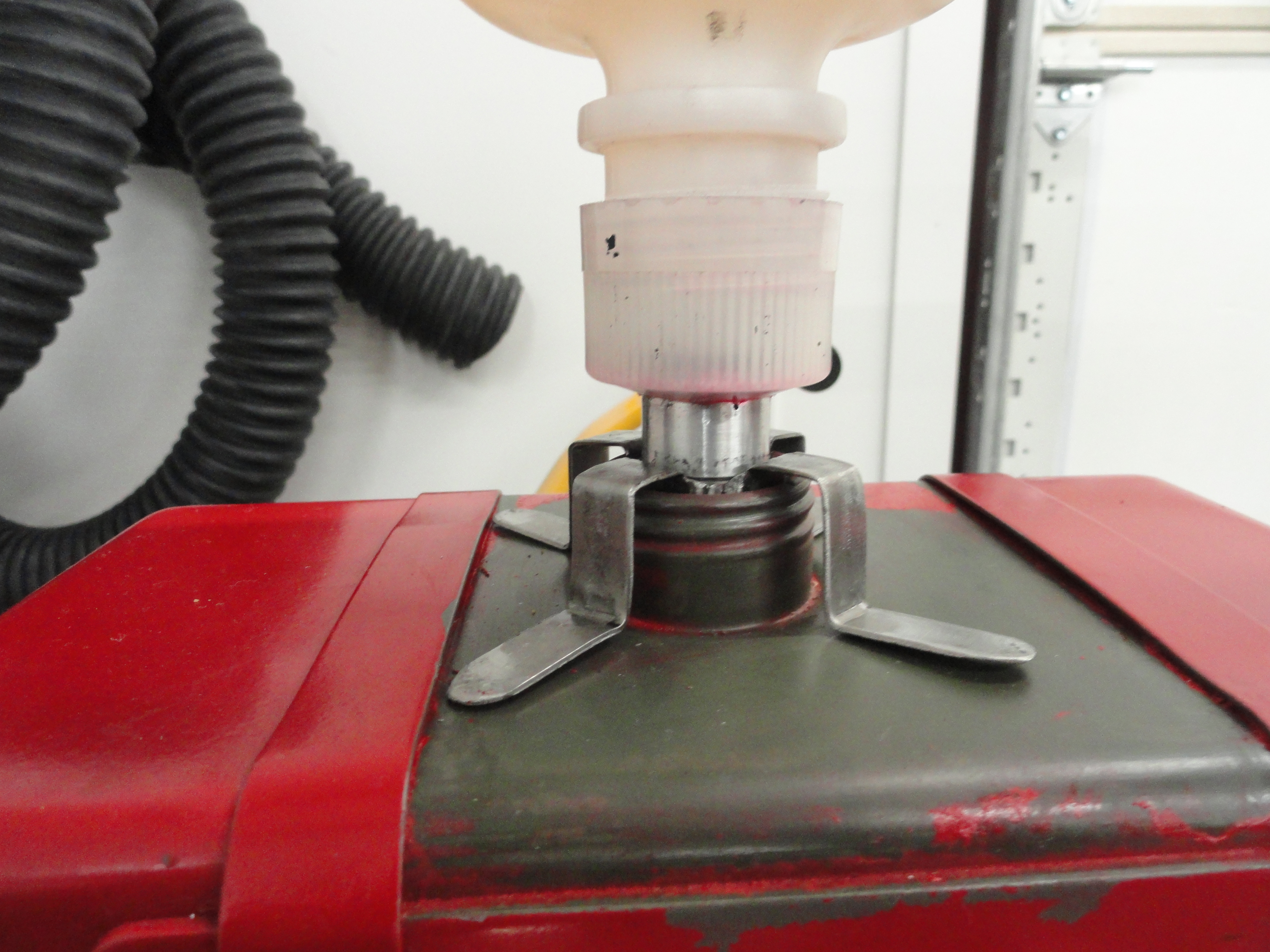
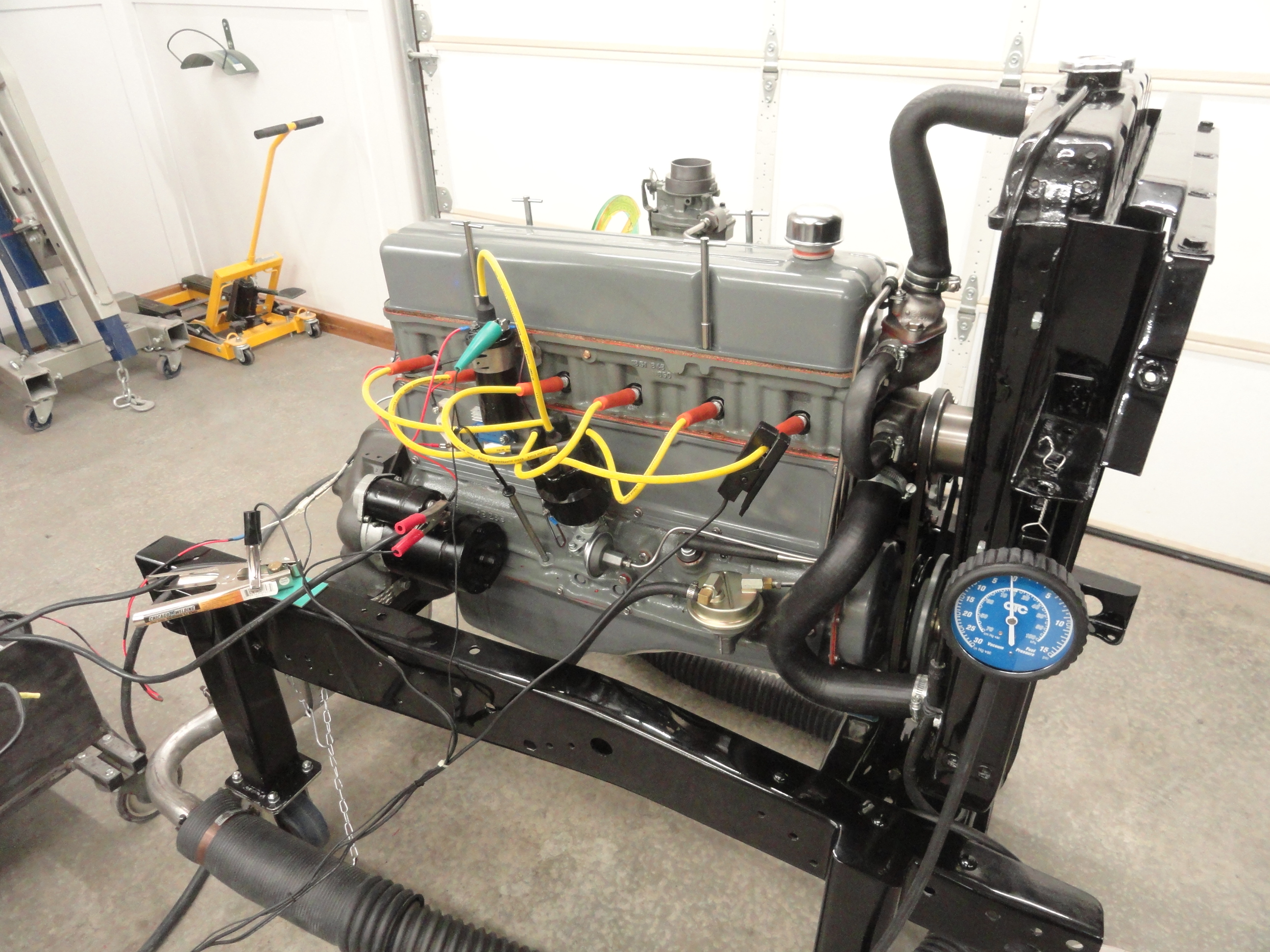
Test Equipment used will be simply a 28 ounce bottle with ounce gradations, a stopwatch, barometer, tachometer, IR Thermometer and the usual compliment of engine gauges. To do these tests I made an adapter for my Start Kart's gas tank. The tank is one gallon but I needed a way to test using a measurement scale. By using a specialized bottle with a unique cap that allows for zero leakage when turned upside down, all that is left is adapting this principle to the existing gas tank. This metal adapter plate is merely two washers welded to four strips of metal, then a level retainer to cause the bottles valve to open once it's in place. This isn't that hard to make and the key thing is to get the bottle opened at a level below the current level of the gas tank so it does not overfill. In this case I have about 1/4 of an inch of air in the tank (excluding the cap area) before it overfills with the bottle in place. Worked out perfect! As the fuel level goes down, the bottle will fill the tank to its full level and give us precise measurement of exactly how much was used.
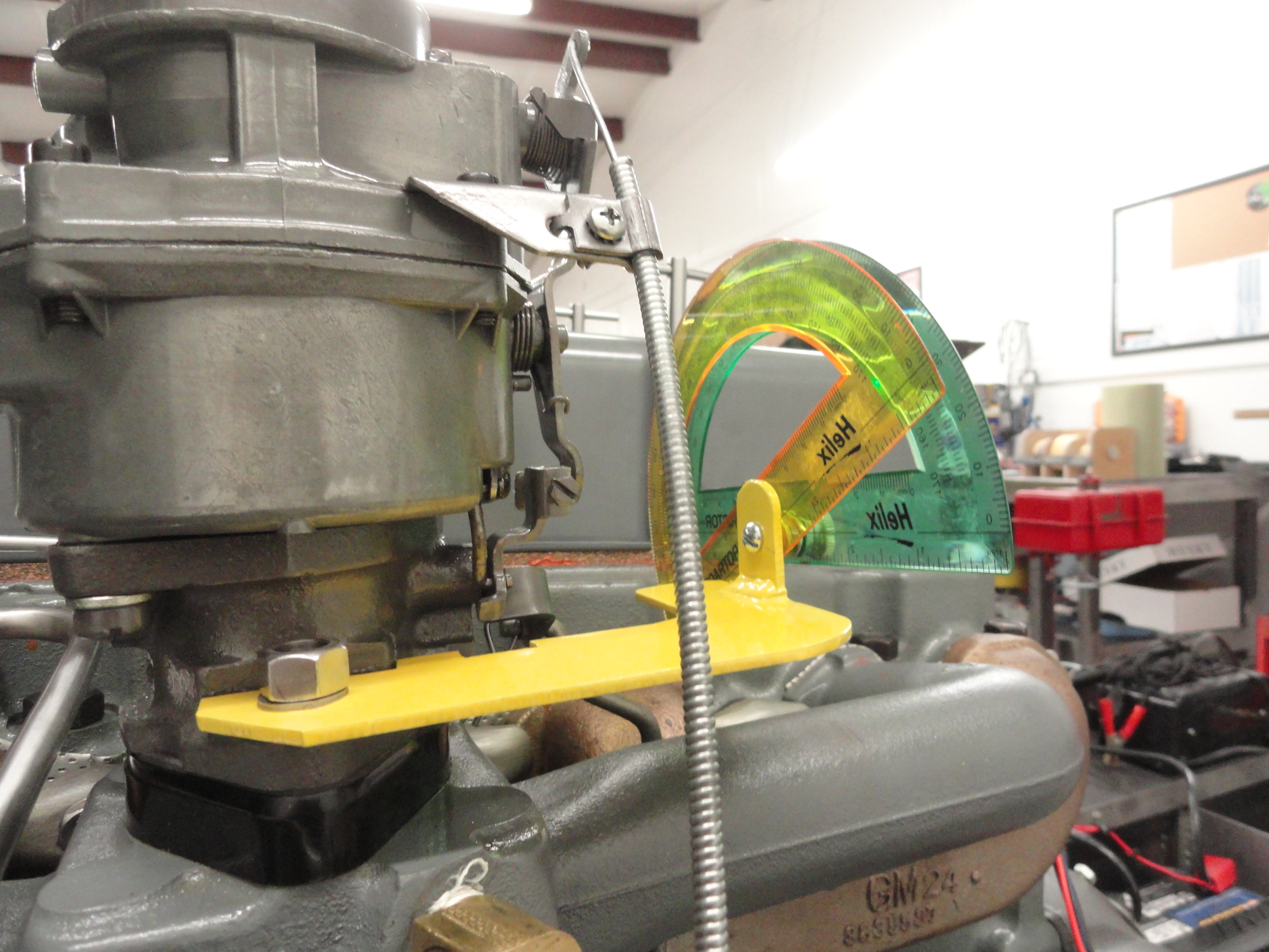
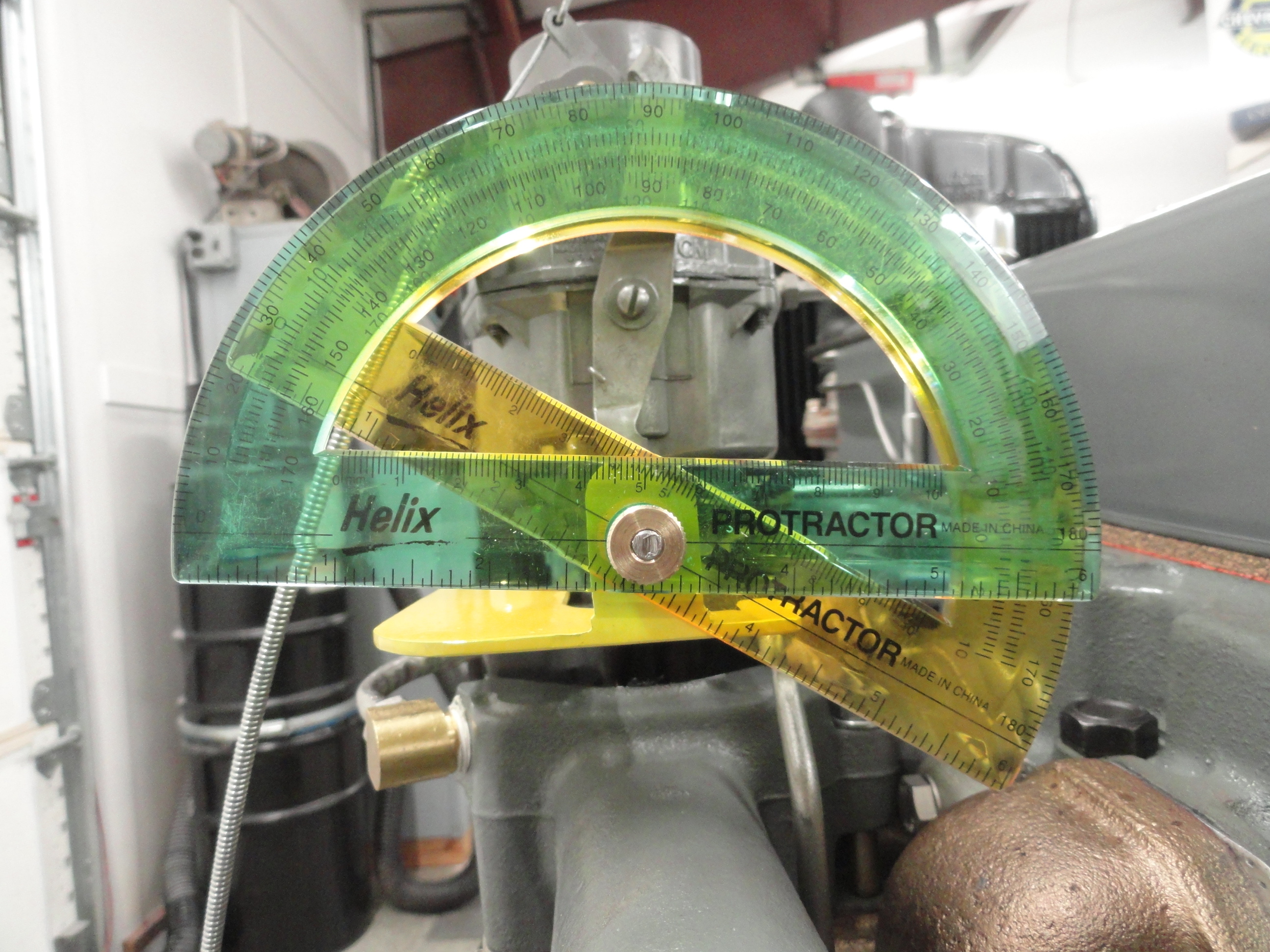
I also needed the ability to measure the amount of throttle it takes to achieve the desired RPM. A few of my friends told me to use a protractor so I did. The yellow protractor is set solidly on ZERO degrees when the stock ignition is at 500 RPM. The Green one will be set to the amount of difference it took to achieve the Ignitions RPM setting. This means even if I have to adjust the throttle screw we can measure using degrees. All of the parameters will be carefully measured for each run. The Protractor's center line is exactly lined up with the throttle's pivot for accuracy. Then, zero degrees is determined and it is tightened down so it will not move throughout the entire process.
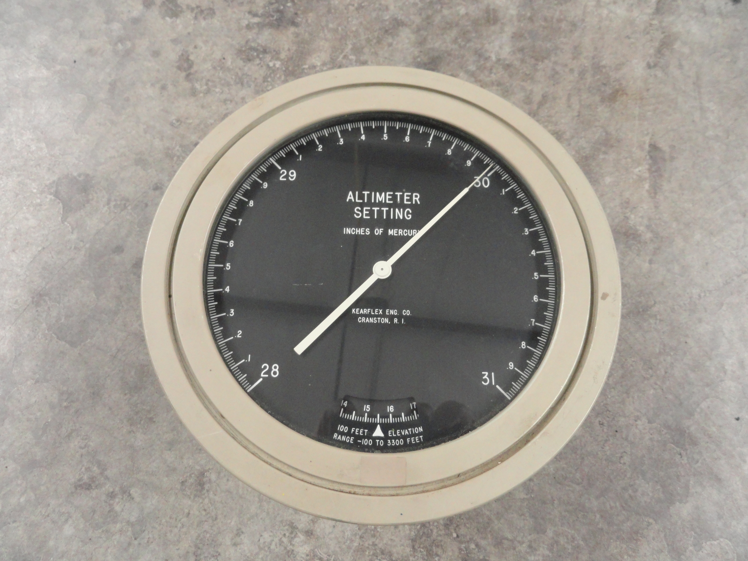
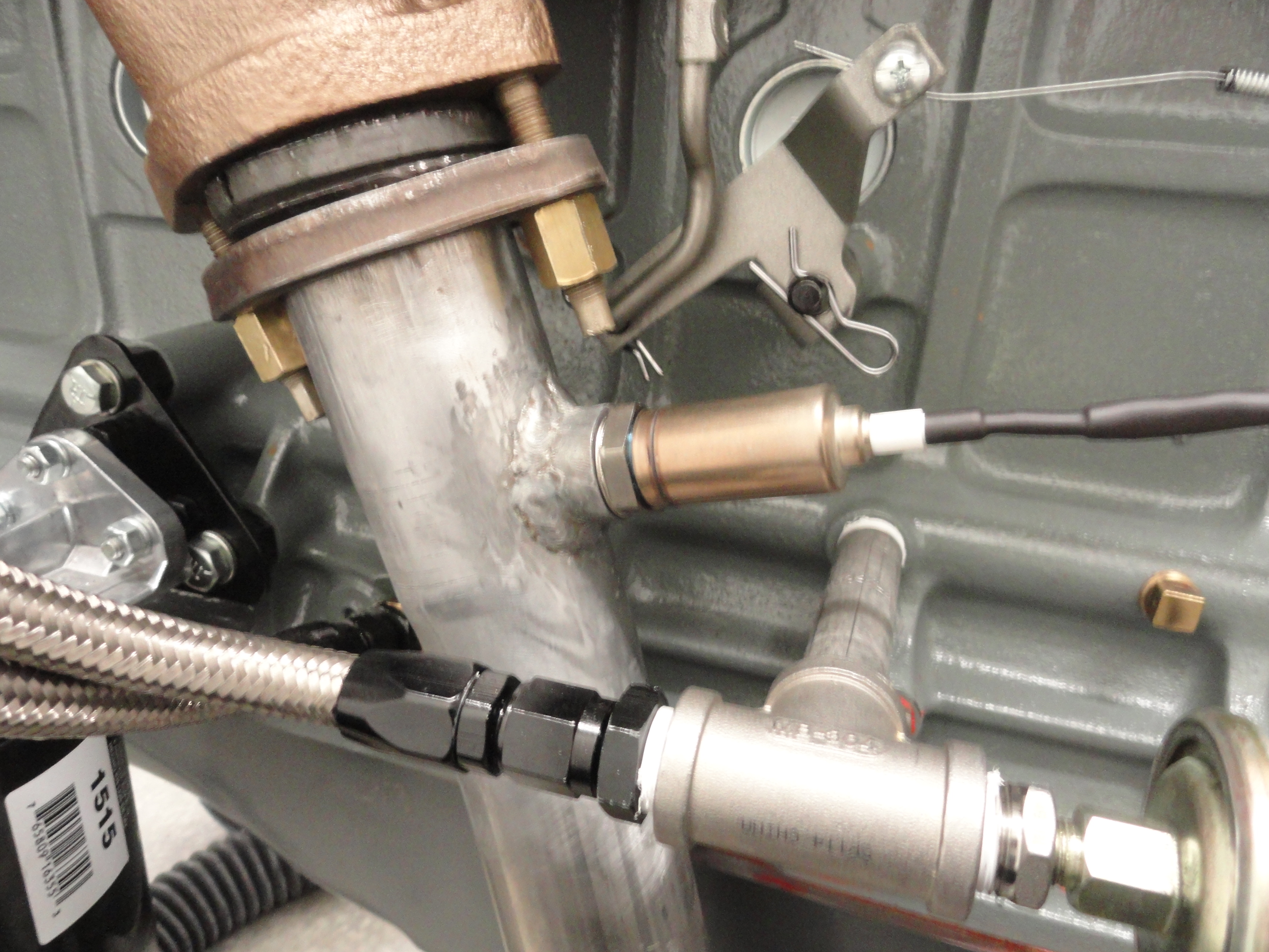
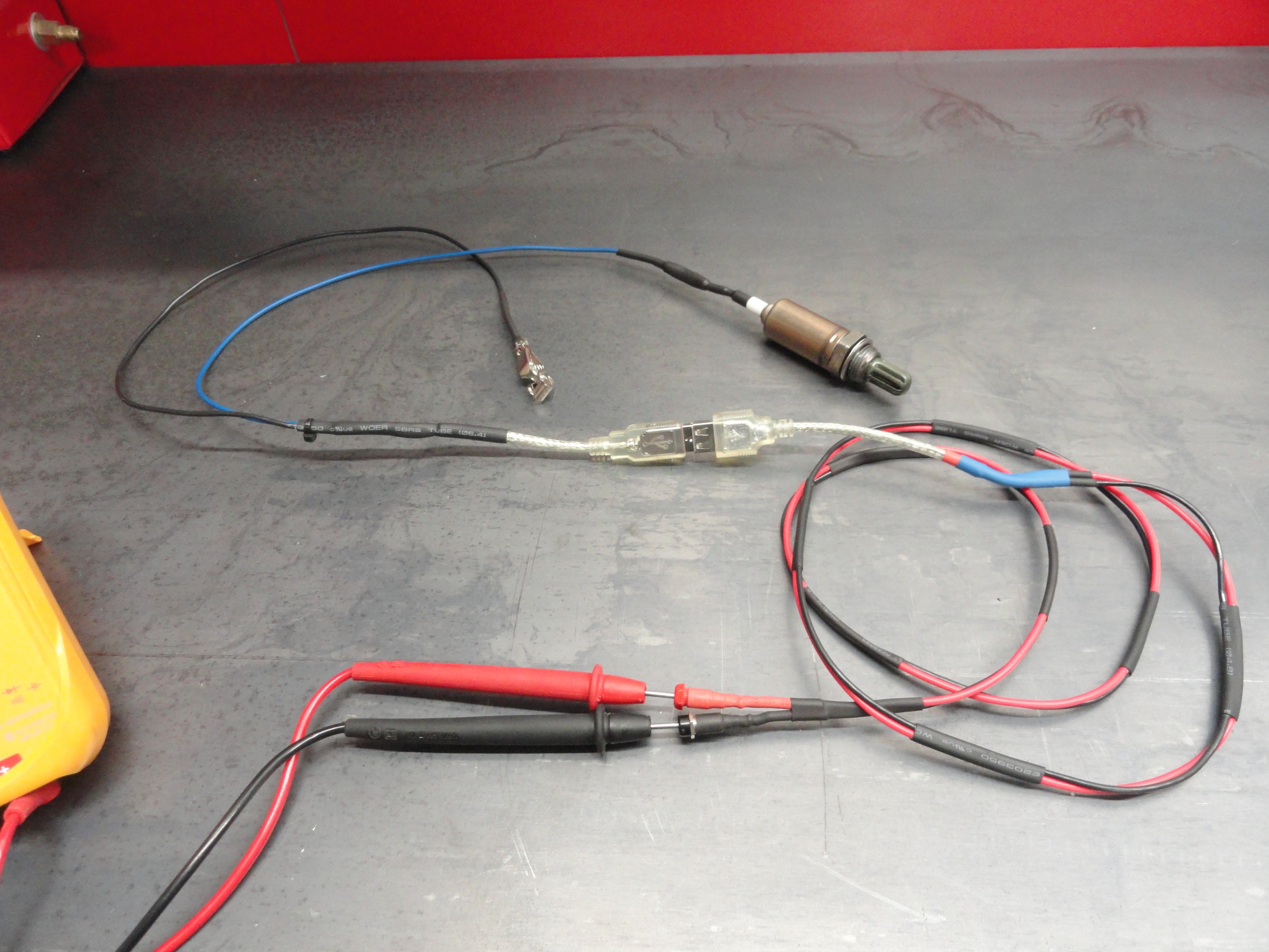
I will also be writing down barometric pressure. This was another suggestion and since I have this nifty barometer why not? The next test parameter may or may not yield usable results. I will be installing an O2 Sensor into the exhaust stream. An O2 Sensor creates as much as 1 volt of electricity depending on your fuel mixture. The optimum fuel mixture is 14.7 parts Oxygen to 1 part fuel or 14.7:1 for gasoline. This would be represented by .5 volts or mid range. If you get below .5 volts, your fuel mixture is too lean (too much oxygen) and if you get more than .5 volts, your fuel mixture is too rich (too much gasoline). Connecting the output of the O2 Sensor to a Voltmeter will give us what we need to determine if we are running too rich or too lean. To install the O2 Sensor, you need a bung that is welded to your exhaust pipe. Since the sensor doesn't put out information until it reaches 600 degrees, it's a good idea to get that sensor as close to the manifold as possible. If you install a heated one, you can get immediate results, but me being so cheap, I opted for the one wire $20 version. I made the test harness to make it easier to take the cables off when the engine isn't being used.
The tests will be conducted as follows:

 High Energy Ignition Tests using Stock Coil (x2) will be as follows:
The results will be very telling as to if HEI has anything to do with better MPG. I will post the complete results here when the tests are complete! The testing will not be over there! I also plan to test stock coils with HEI to determine the importance of having an expensive and incompatible with stock ignition Coil.
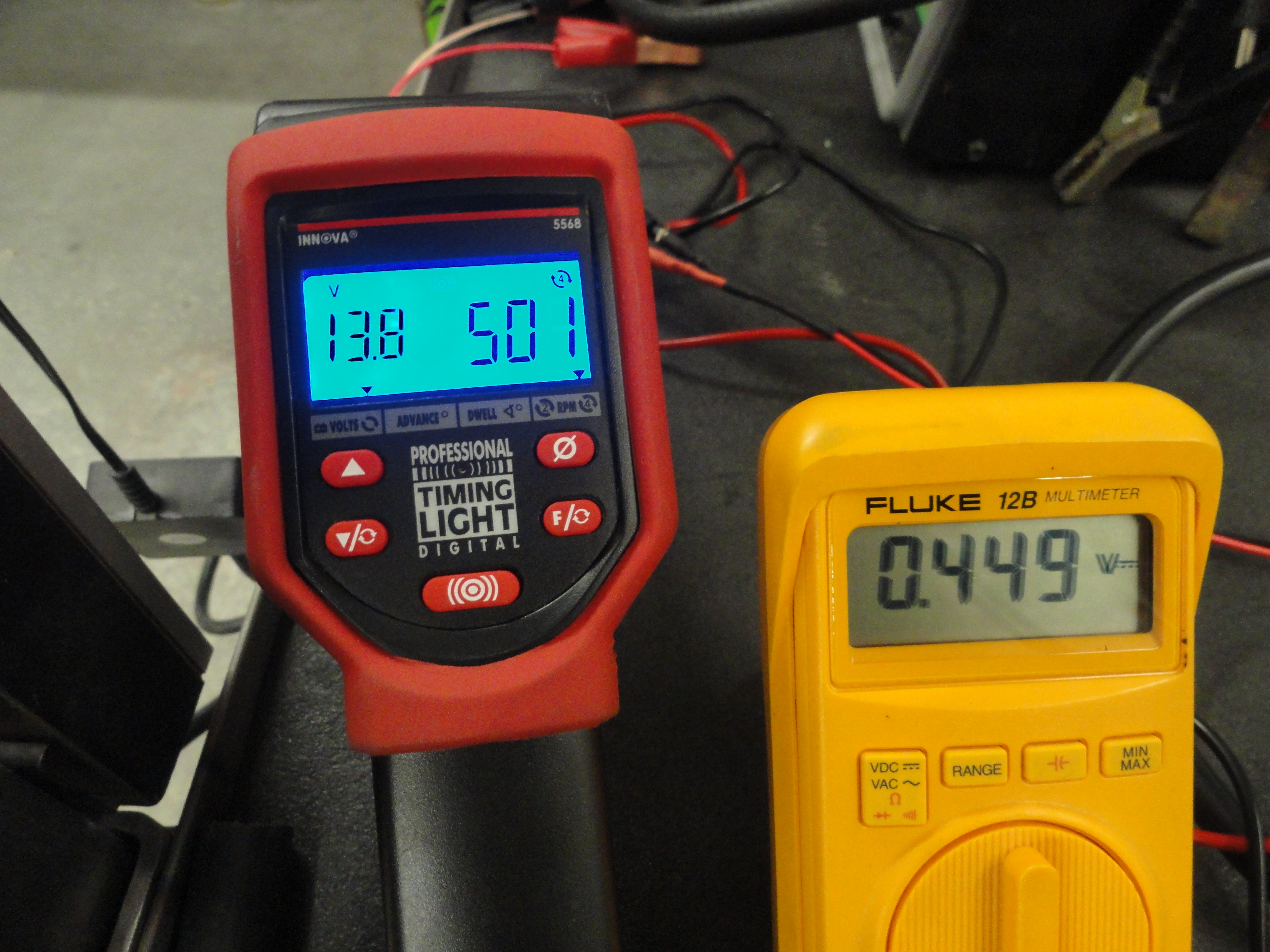
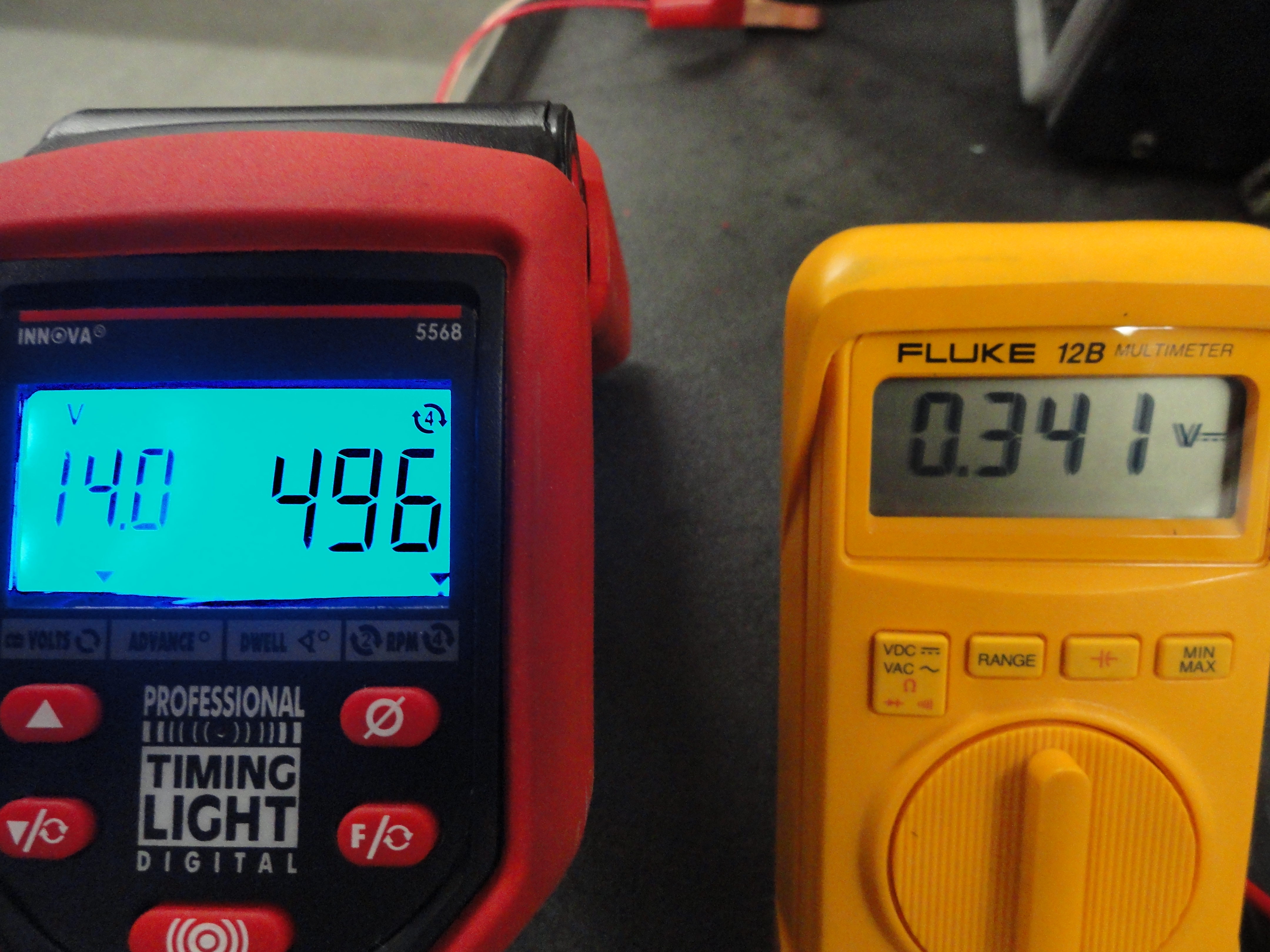
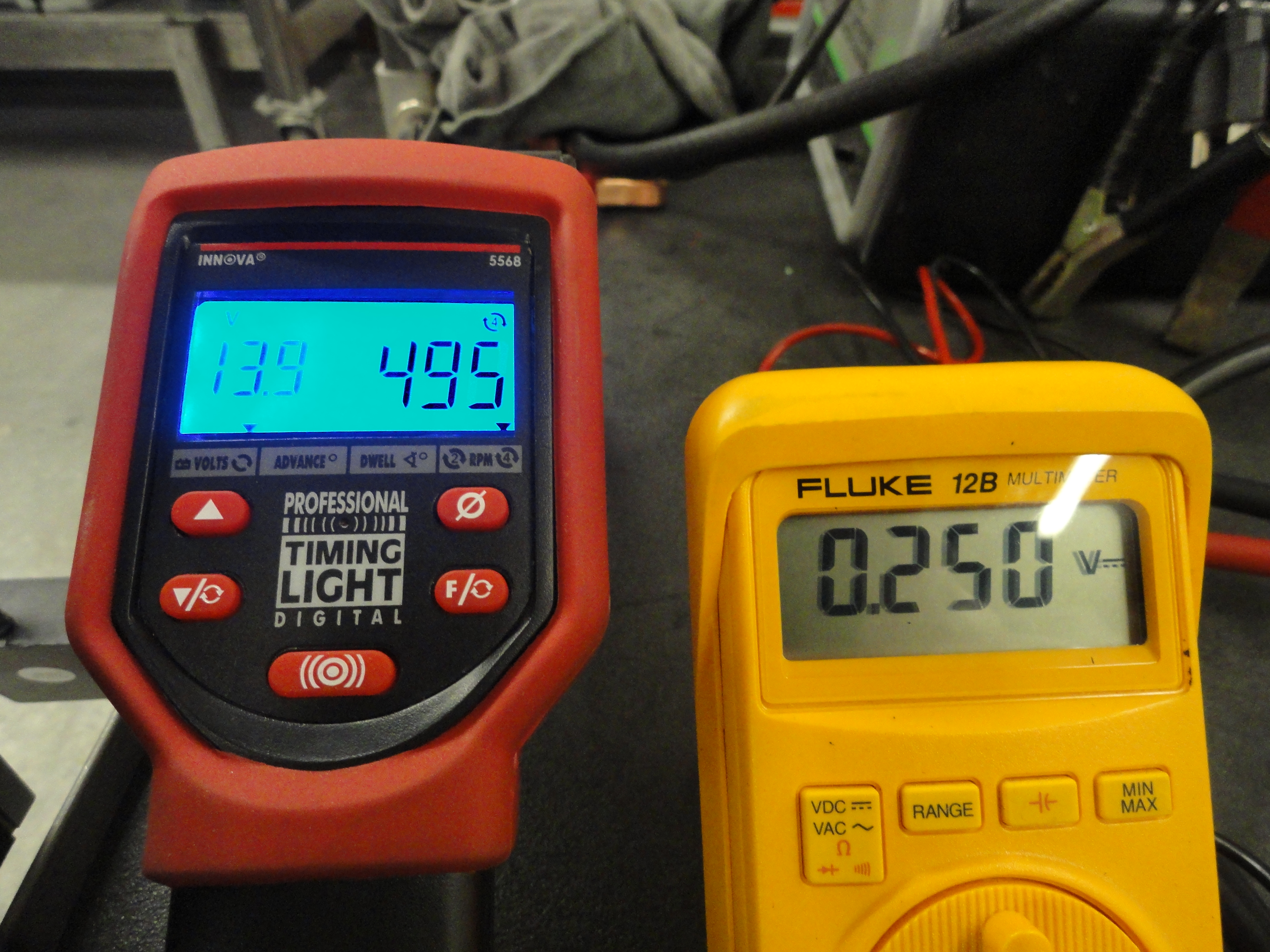
Test One: Stock Ignition at Idle (.035 Plug Gap)
|
|
|
|
|
|
|
|
|
|
|
|
|
|
|
|
|
|
|
|
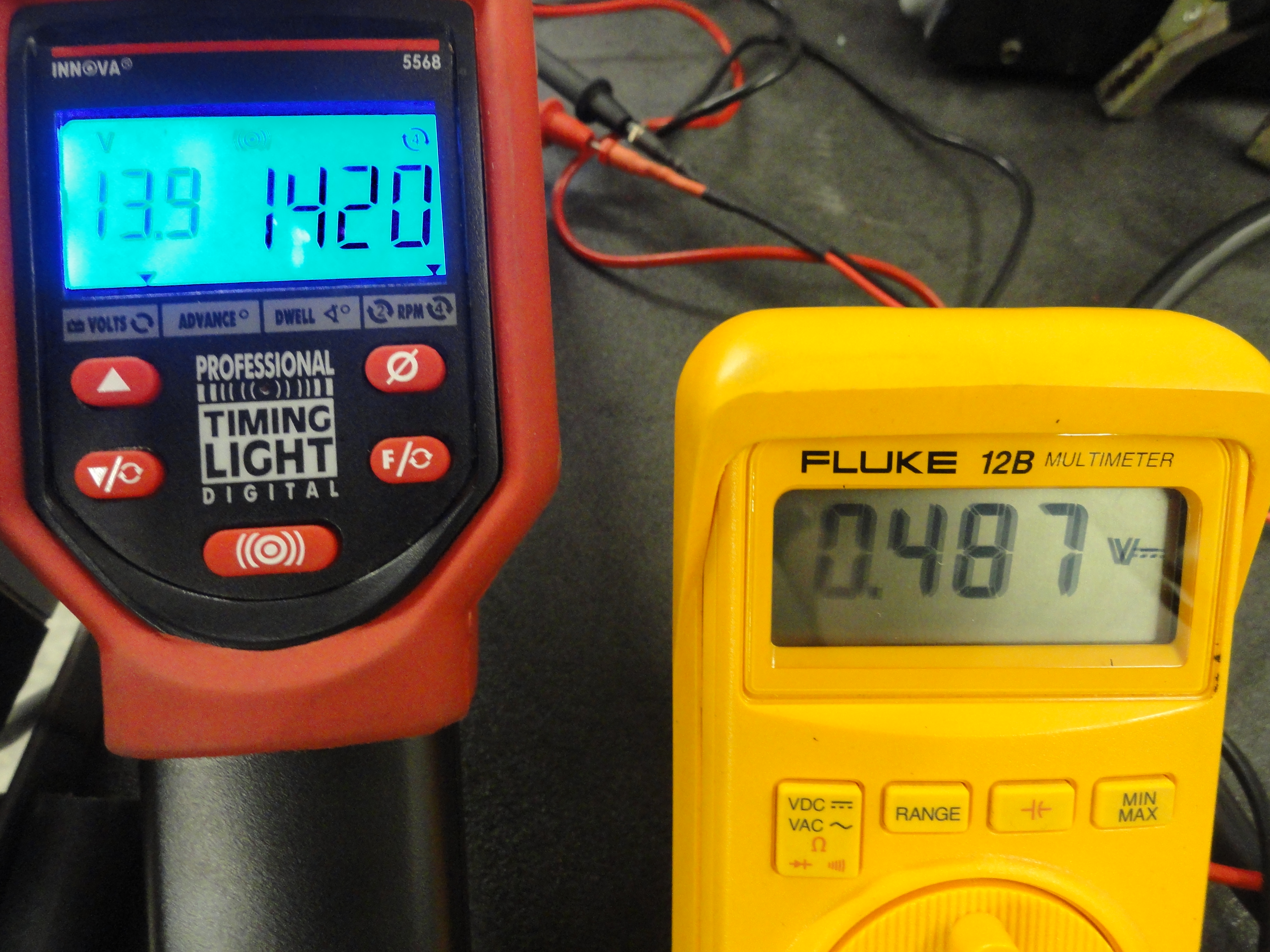
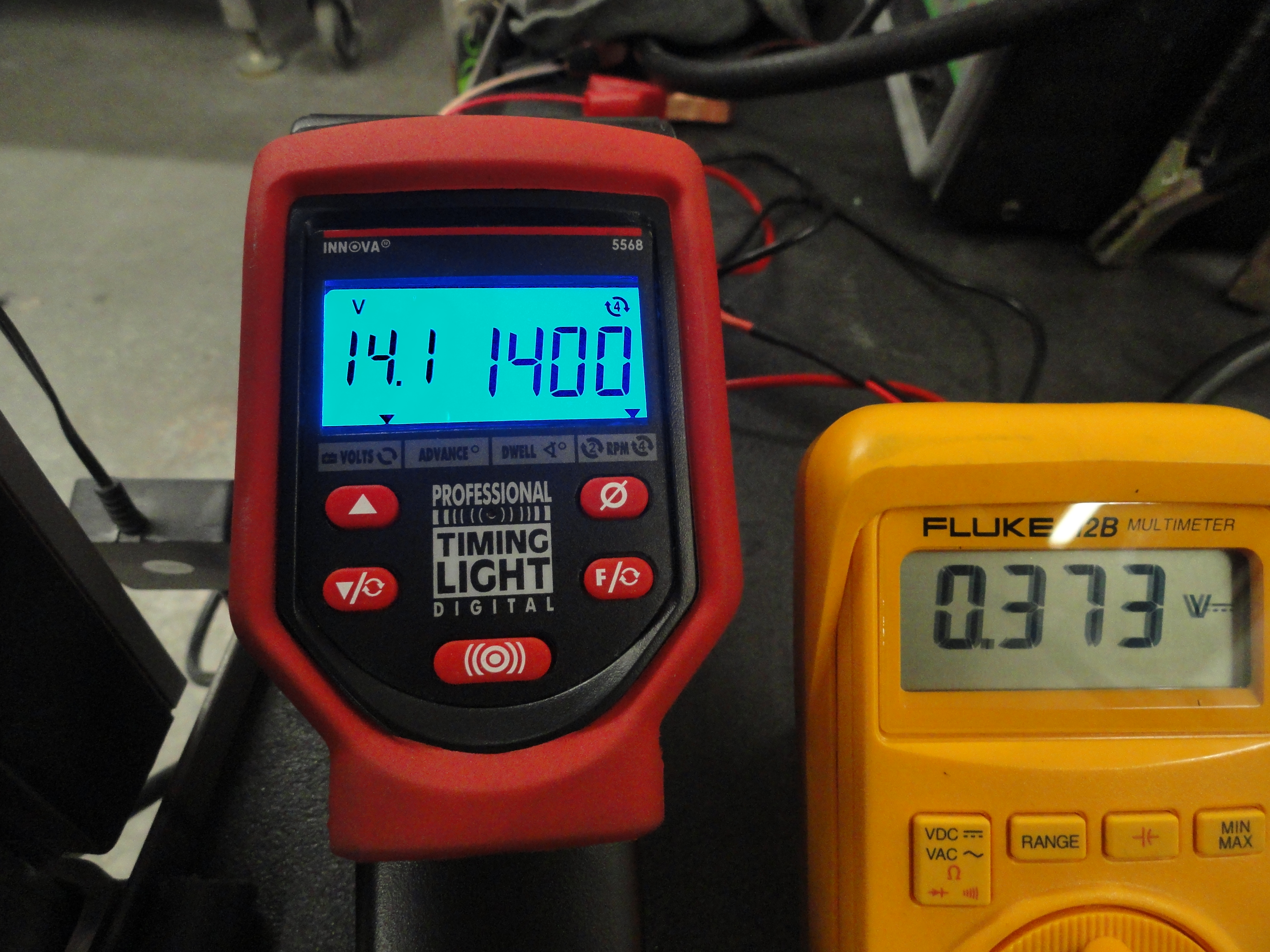
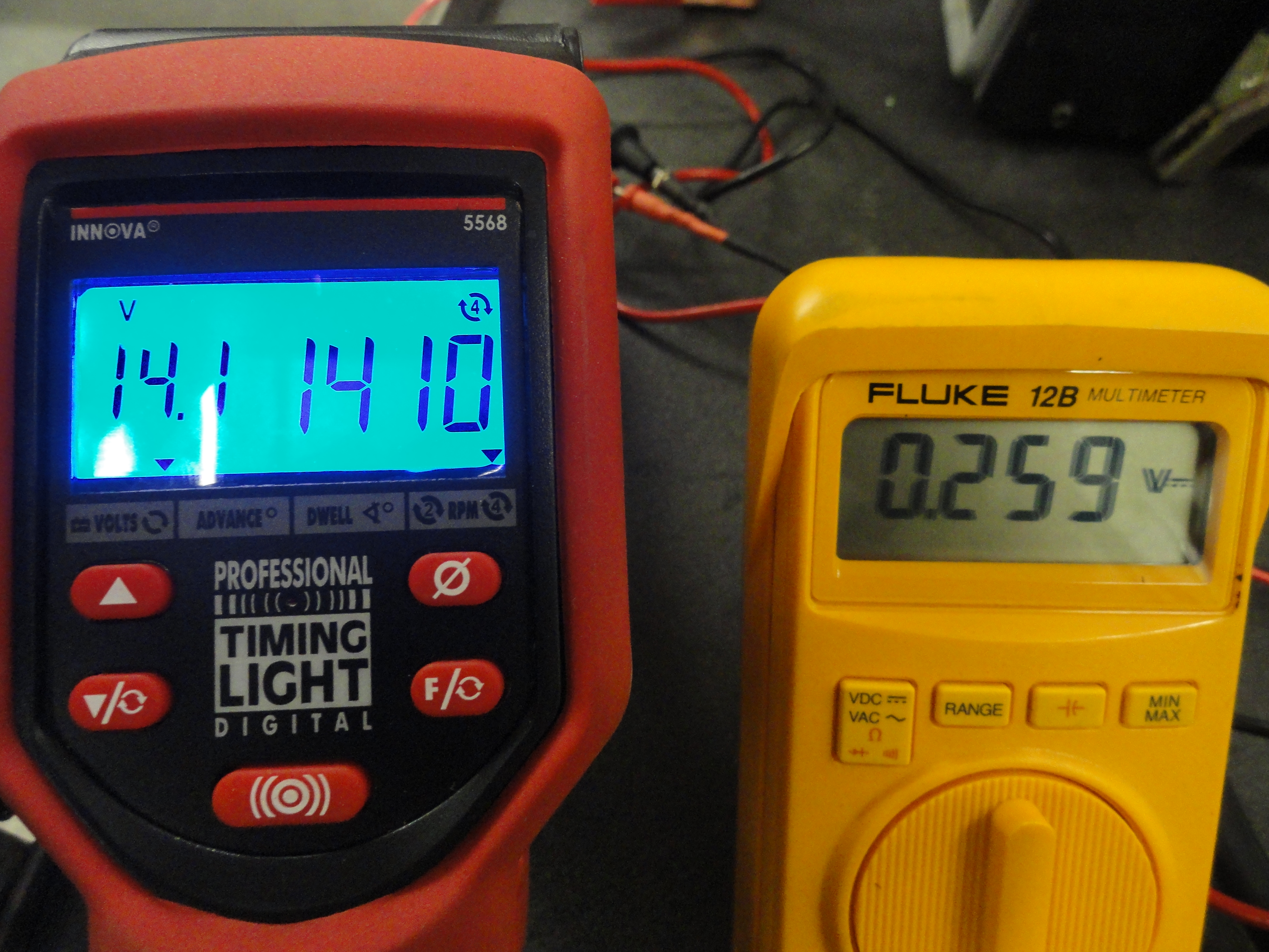
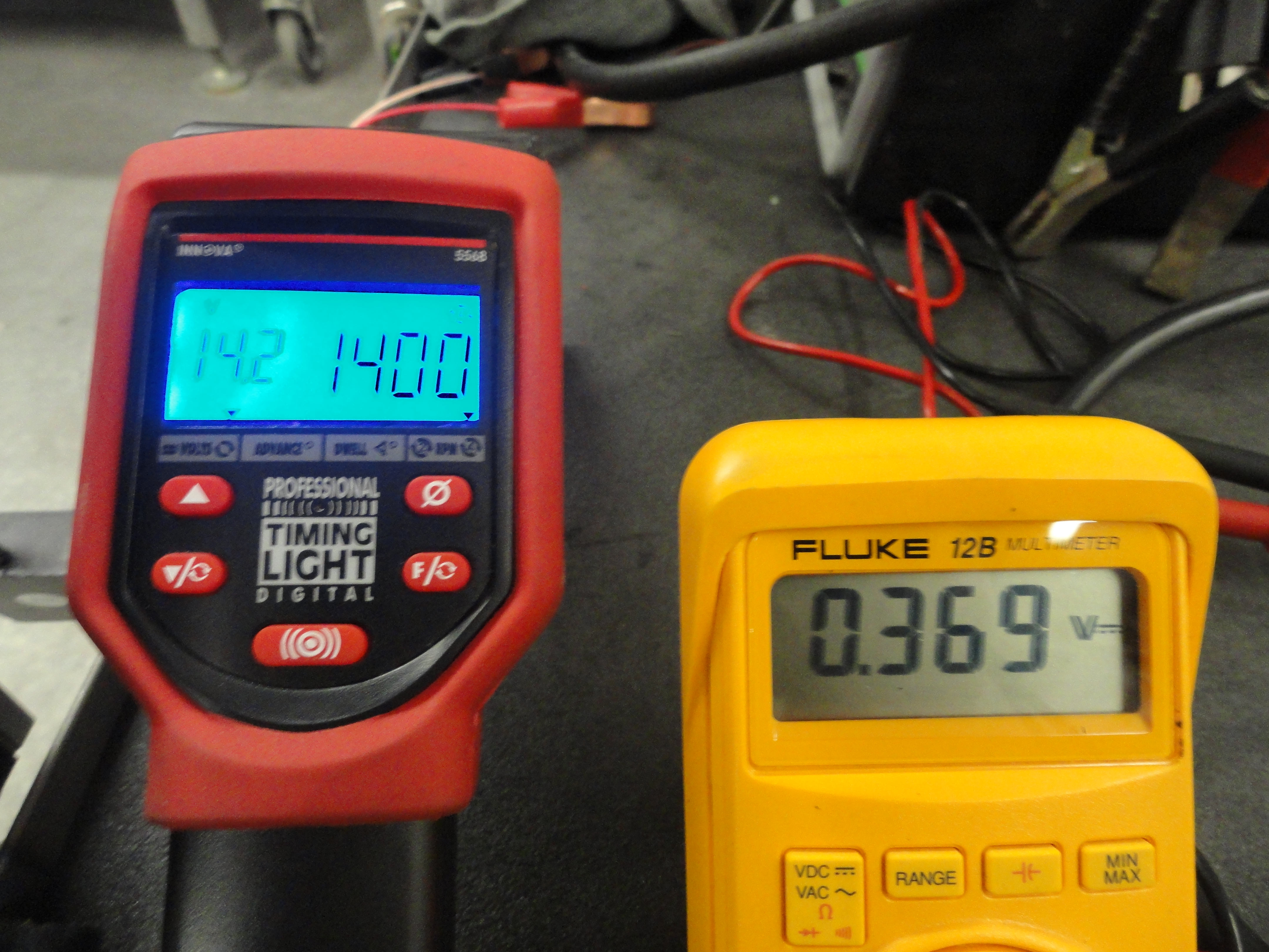
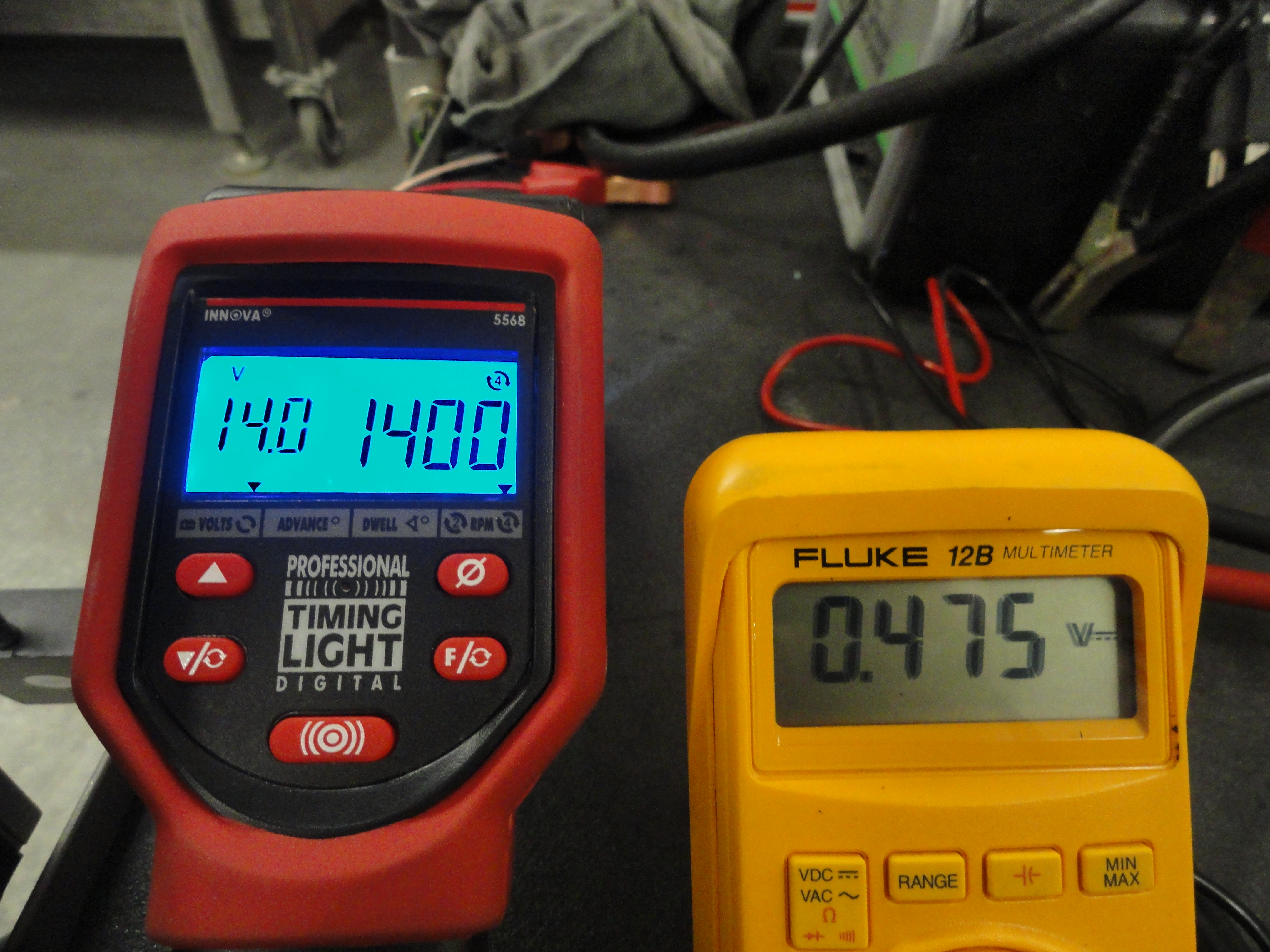
Test Two: Stock Ignition at 1401 RPM/30 MPH (.035 Plug Gap)
|
|
|
|
|
|
|
|
|
|
|
|
|
|
|
|
|
|
|
|
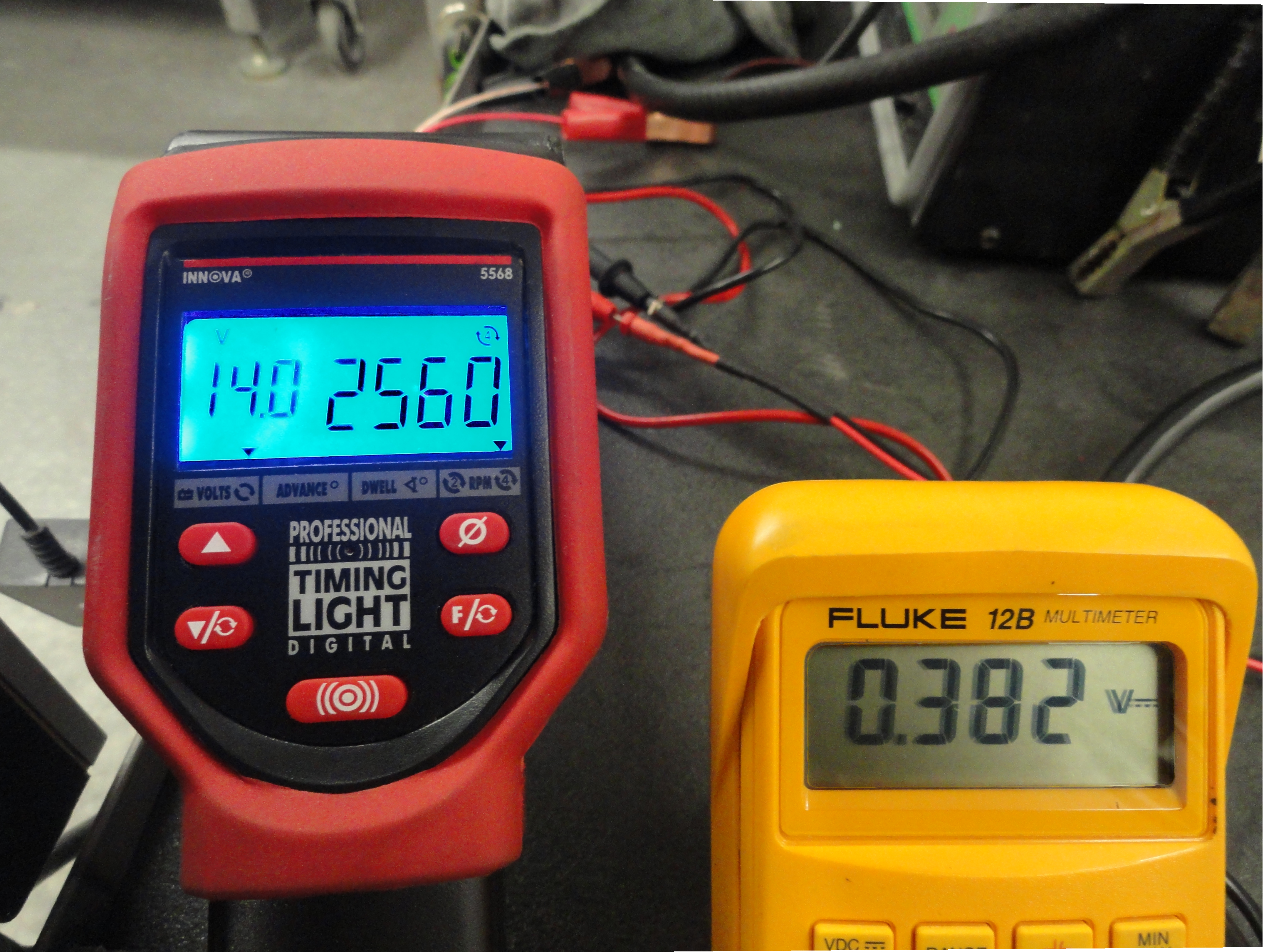
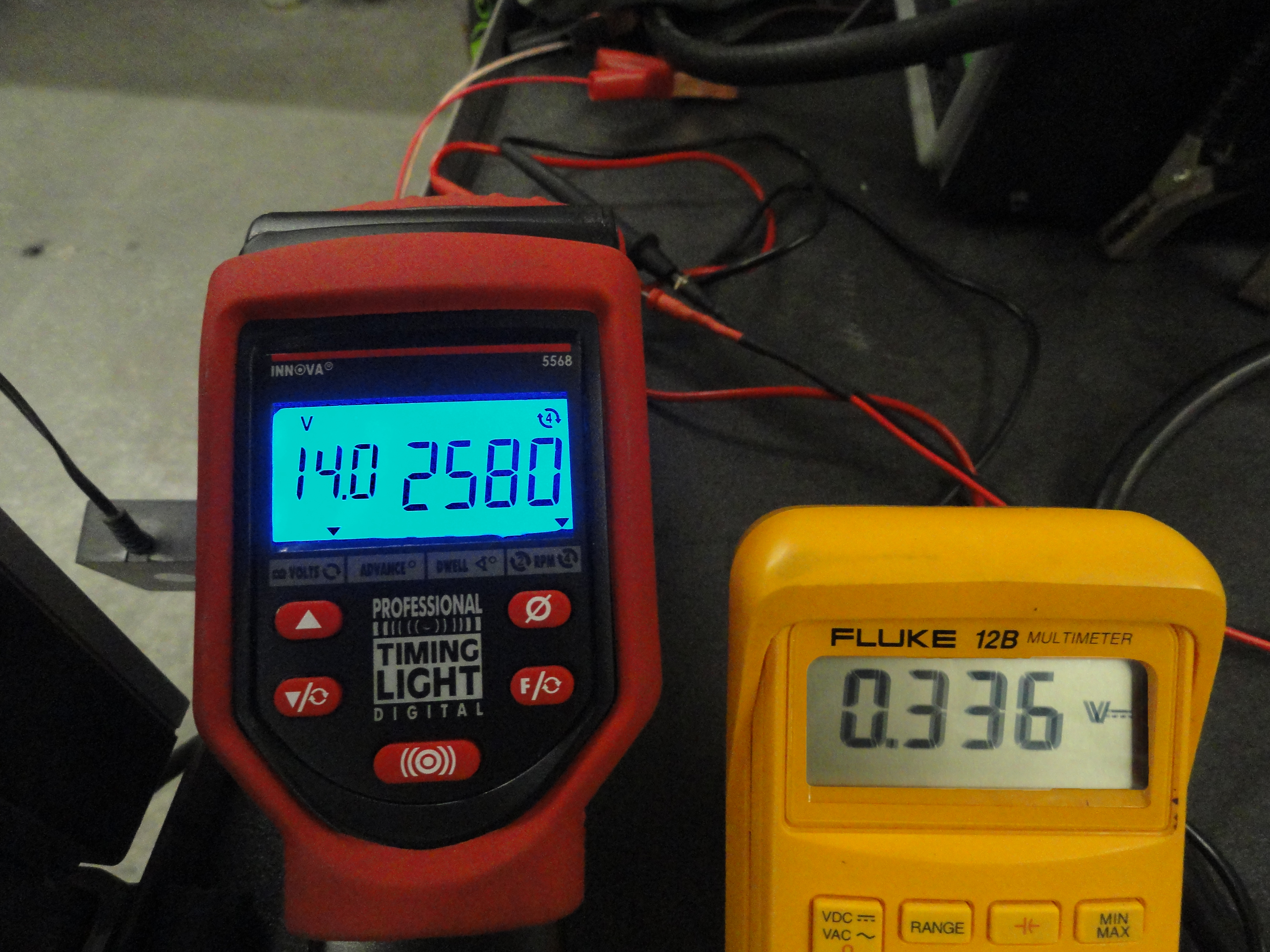
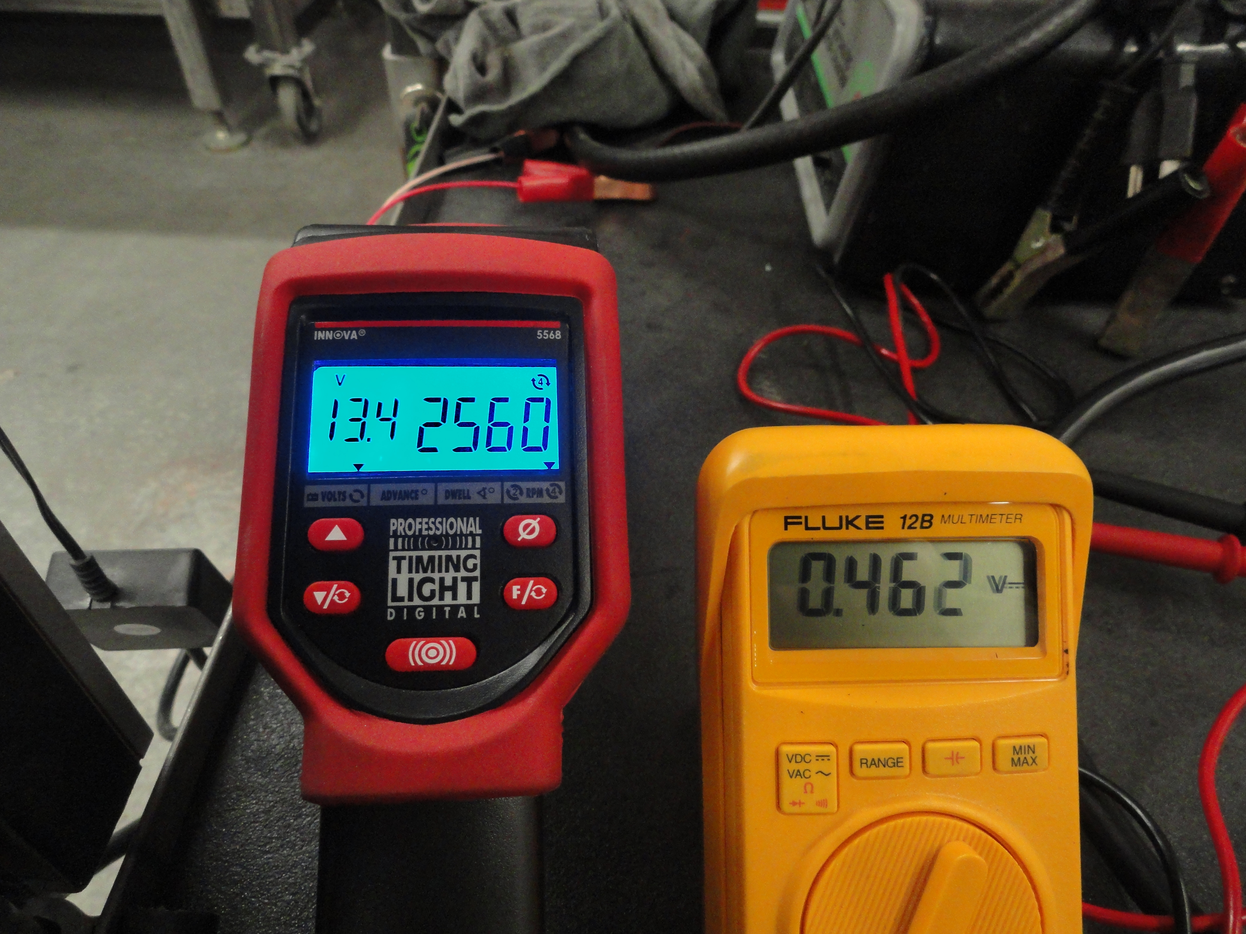
Test Three: Stock Ignition at 2568 RPM/55 MPH (.035 Plug Gap)
|
|
|
|
|
|
|
|
|
|
|
|
|
|
|
|
|
|
|
|

Test Four: Stock Ignition at Idle (.040 Plug Gap)
|
|
|
|
|
|
|
|
|
|
|
|
|
|
|
|
|
|
|
|
Test Five: Stock Ignition at 1401 RPM/30 MPH (.040 Plug Gap)
|
|
|
|
|
|
|
|
|
|
|
|
|
|
|
|
|
|
|
|
Test Six: Stock Ignition at 2568 RPM/55 MPH (.040 Plug Gap)
|
|
|
|
|
|
|
|
|
|
|
|
|
|
|
|
|
|
|
|

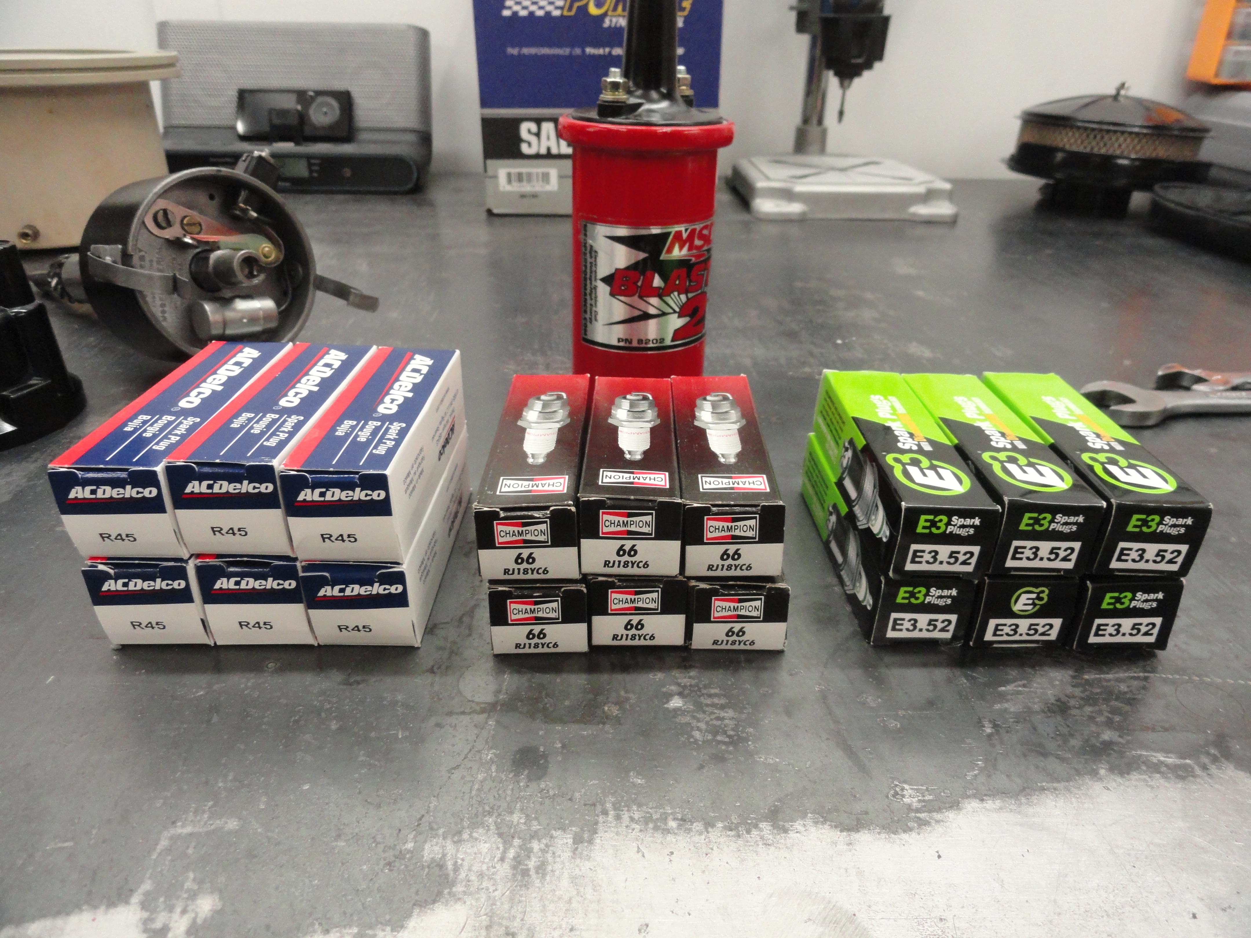
With the Stock Ignition system numbers recorded we can now move on to test the HEI System. For this test we will install the HEI adapter plate, reluctor, reluctor pickup and wiring into the distributor. We will connect the GM HEI Module to the Distributor and Coil. Our first HEI tests will be using an MDT 45,000 Volt Coil and special "High Gap" Champion Spark Plugs to achieve the gaps we need for HEI. The engine parameters will remain exactly the same as the stock tests to ensure accurate data.
Test Seven: HEI Ignition at Idle (.035 Plug Gap)
|
|
|
|
|
|
|
|
|
|
|
|
|
|
|
|
|
|
|
|
Test Eight: HEI Ignition at 1401 RPM/30 MPH (.035 Plug Gap)
|
|
|
|
|
|
|
|
|
|
|
|
|
|
|
|
|
|
|
|
Test Nine: HEI Ignition at 2568 RPM/55 MPH (.035 Plug Gap)
|
|
|
|
|
|
|
|
|
|
|
|
|
|
|
|
|
|
|
|

Test Ten: HEI Ignition at Idle (.045 Plug Gap)
|
|
|
|
|
|
|
|
|
|
|
|
|
|
|
|
|
|
|
|
Test Eleven: HEI Ignition at 1401 RPM/30 MPH (.045 Plug Gap)
|
|
|
|
|
|
|
|
|
|
|
|
|
|
|
|
|
|
|
|
Test Twelve: HEI Ignition at 2568 RPM/55 MPH (.045 Plug Gap)
|
|
|
|
|
|
|
|
|
|
|
|
|
|
|
|
|
|
|
|
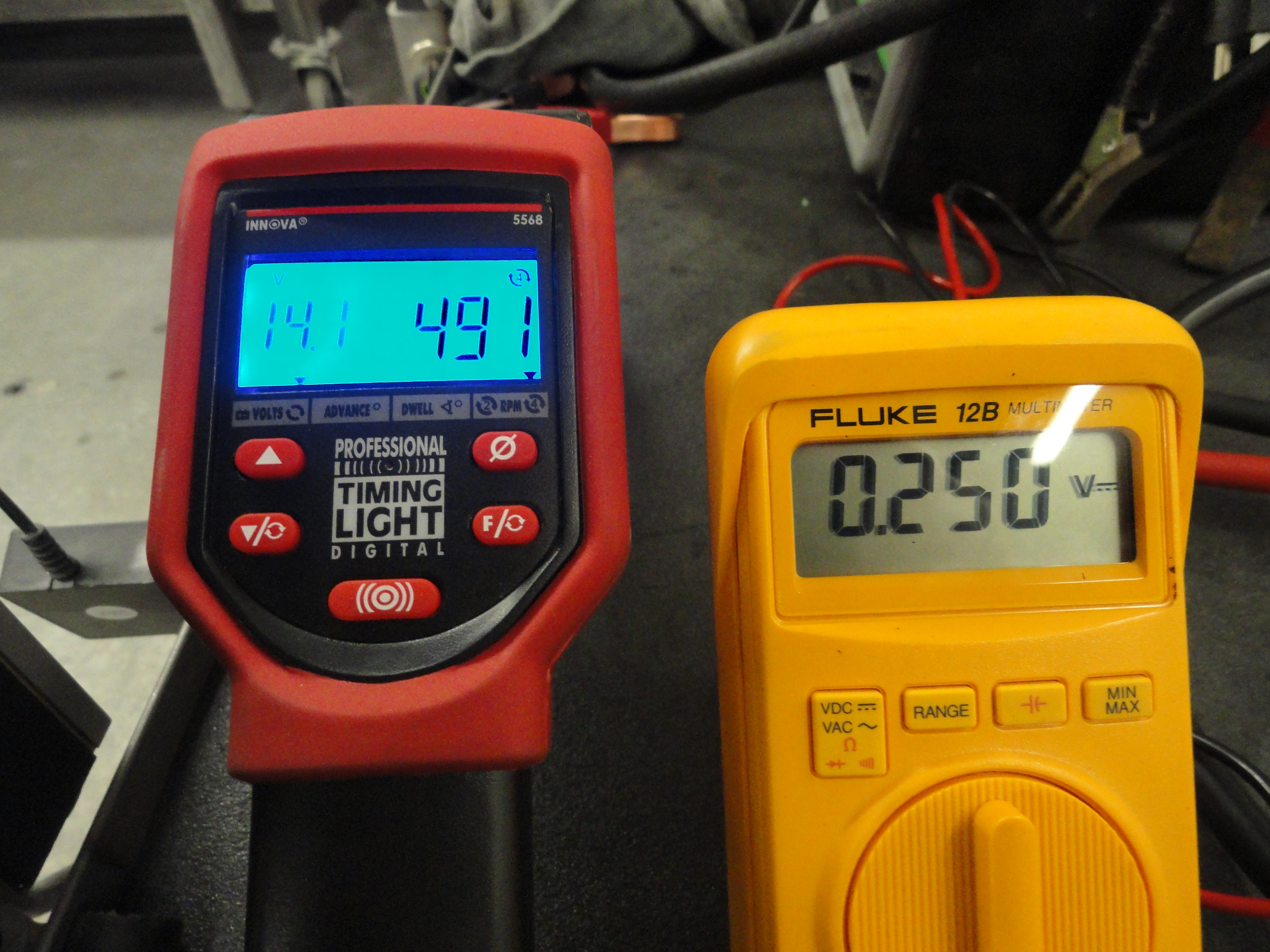
Test Thirteen: HEI Ignition at Idle 500 RPM (.060 Plug Gap)
|
|
|
|
|
|
|
|
|
|
|
|
|
|
|
|
|
|
|
|
Test Fourteen: HEI Ignition at 1401 RPM/30 MPH (.060 Plug Gap)
|
|
|
|
|
|
|
|
|
|
|
|
|
|
|
|
|
|
|
|
Test Fifteen: HEI Ignition at 2568 RPM/55 MPH (.060 Plug Gap)
|
|
|
|
|
|
|
|
|
|
|
|
|
|
|
|
|
|
|
|


I ran these tests the way I learned to run laboratory tests when I was a lab rat at Sandia National Labs. You do not favor one test over another in any way. You just run the tests and write down the results. You make sure you have the proper controls in place so each test is repeatable. I am confident that I could run these same tests over again, and have very similar results.
The conclusions are pretty clear. Properly gapped at .045, the HEI system has the fuel savings advantage. It also runs stronger since it takes away the dwell and timing duties and gives that to the computer. It is obvious at this level that THE weakest part of the 235 engine is now the Carb. Once the Ignition system is this clean, you can really see how misting into a single manifold stream to fire 6 different firing systems in a clean and reliable way does not really describe a Carburetor! I am very pleased that I can now say with total confidence the HEI wins on all counts. I encourage you to test for yourself if you are not absolutely convinced.
Since this particular HEI uses the Stock Distributor without making any modifications to the vintage parts, we want to look at a few other related issues. For example, this is not only cool because you can't tell it from stock, it's also cool because it is the least expensive solution out there. The DIY nature of this project guarantees that. If you are not a performance geek who wants the best of the best, we can eliminate one of the higher cost items... the MSD 45,000 Volt Coil. The stock coil will run the HEI just as well as the stock points system. So, if you want a more reliable, more trouble free system, but don't want a second coil laying around, bypass the Ballast Resistor (just a temporary jumper wire will do) and enjoy the reliability of the HEI system. BUT... what is the fuel mileage penalty and performance penalties you ask? Let's find out:
This test will be using the stock coil but bypassing the ballast resistor but other than that, the HEI system is intact. The reason for bypassing the Ballast Resistor is because we do not need a higher ohms system than we have to. We need as close to 12 volts at the negative side of the coil as possible. It also stands to reason the coil does not put out enough high voltage to keep the gaps as high, so the best compromise is to use a gap of .040. You can then compare the .040 gap tests using the stock ignition system (tests 4-6) to see how well you are doing.
Test Sixteen: HEI Ignition at Idle (.040 Plug Gap) using the Stock Ignition Coil (No Ballast Resistor)
|
|
|
|
|
|
|
|
|
|
|
|
|
|
|
|
|
|
|
|
Test Seventeen: HEI Ignition at 1401 RPM/30 MPH (.040 Plug Gap) using the Stock Ignition Coil (No Ballast Resistor)
|
|
|
|
|
|
|
|
|
|
|
|
|
|
|
|
|
|
|
|
Test Eighteen: HEI Ignition at 2568 RPM/55 MPH (.040 Plug Gap) using the Stock Ignition Coil (No Ballast Resistor)
|
|
|
|
|
|
|
|
|
|
|
|
|
|
|
|
|
|
|
|
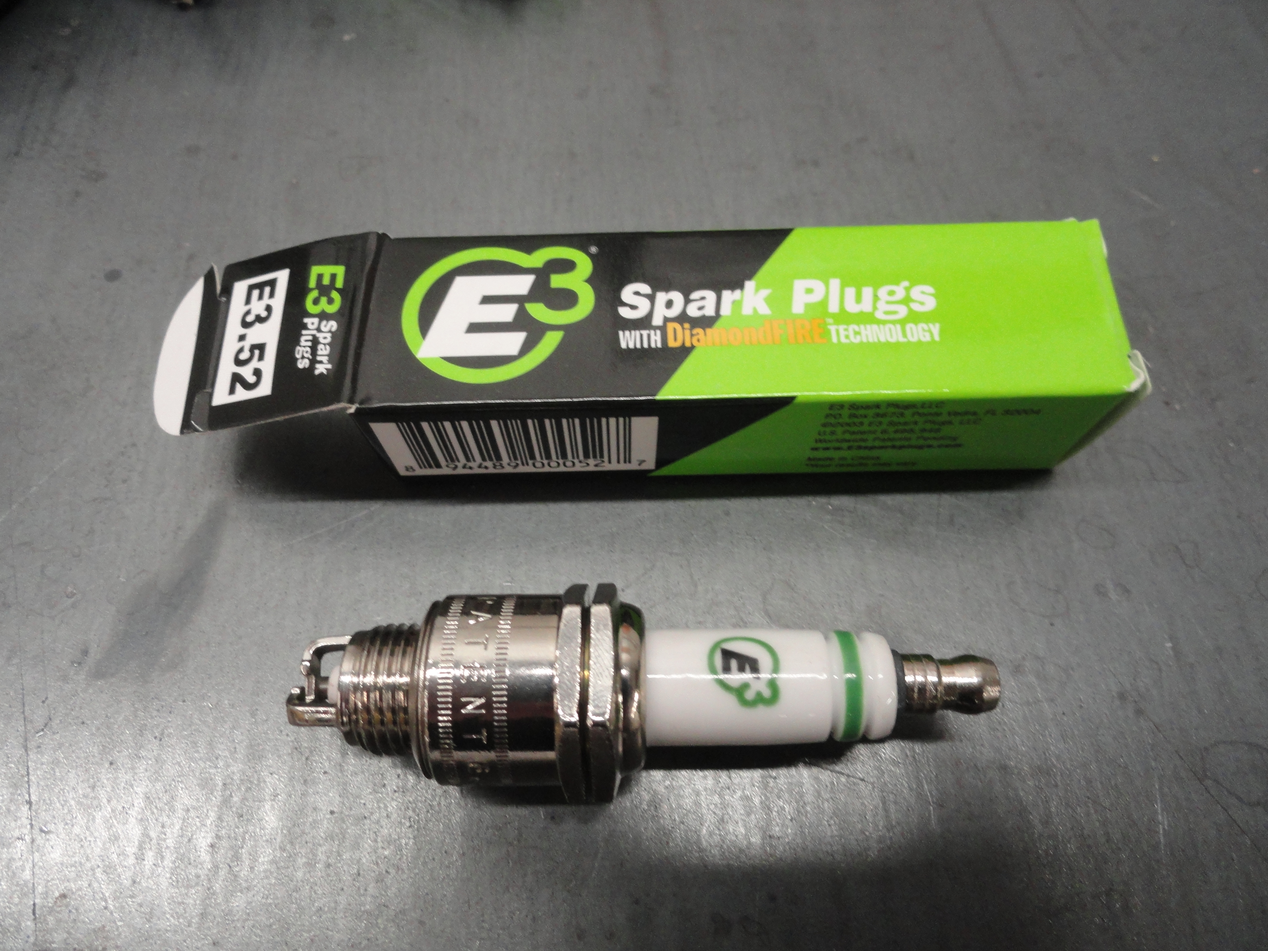
Test Nineteen: HEI Ignition at Idle (.040 Plug Gap) using the Stock Ignition Coil (No Ballast Resistor) Didn't we already do this? Well, I want to throw in another anomaly... I have this habit of watching PowerBlock TV on the weekends and they like to tout the wonders of the "E3 Spark Plug with DiamondFire Technology/Made in China/Your Results May Vary" Well, let's see how the previous tests compare with the only difference being stock plugs Vs. E3. E3 Plugs are not gap-able and are gapped at .040. So, run the tests if you don't believe it, but compare tests 19-21 with tests 16-18. I will let YOU say it!
|
|
|
|
|
|
|
|
|
|
|
|
|
|
|
|
|
|
|
|
Test Twenty: HEI Ignition at 1401 RPM/30 MPH (.040 Plug Gap) using the Stock Ignition Coil (No Ballast Resistor)(E3)
|
|
|
|
|
|
|
|
|
|
|
|
|
|
|
|
|
|
|
|
Test Twenty One: HEI Ignition at 2568 RPM/55 MPH (.040 Plug Gap) using the Stock Ignition Coil (No Ballast Resistor)(E3)
|
|
|
|
|
|
|
|
|
|
|
|
|
|
|
|
|
|
|
|

Conclusions: Turns out the HEI system (.045 Gap) with the 45kv Coil is the best running and gets the best mileage. This is not necessarily the best for you however. Maybe you would like to save a few bucks and go with the stock coil and stock plugs. The results of these tests give you many options. It has been a very rewarding test session! I was able to test my engine out in various configurations while providing some very useful data for those interested in Ignition Systems. I am not one of those who like to go on gut feelings, so now if anyone wants proof that HEI's do better with hotter spark and wider gap, or if fuel economy numbers is what they are looking for, you now have a place to go! This project only set me back for about 3.281 gallons of gas!
The Vac Advance is Optional! Jim Linder, the renowned ignition specialist we used for most of the technical aspects of this HEI modification says that if you feel the system runs better in all ranges without the vac advance, don't be surprised. The GM HEI module controls the dwell and timing using the RPM as its trigger, so it is entirely possible that you will find the vac advance unnecessary. To take the Vac Advance out of the equation, but keep it for aesthetics, drill a small hole in the vac advance mount for a screw and nut that in effect bolts the two parts of the mount together solidly. It is not enough to just block off the vacuum to it. You want that distributor solidly mounted in place like the stock system does not allow for. You can test this by using a small vise grip to hold them tightly, then unhook the vac from the base of the carb. The mechanical advance is still an integral part of the system. Since this is more of an individual preference, I will not bother trying to justify it one way or the other. I think testing is complete for the time being! Thanks and stay tuned for the rollout of the kits we are putting together for this.
Special Thanks to 32Vid (Jeffrey) and JoeH were especially helpful in helping me design the tests. Keep checking devestechnet.com and our forums from time to time for new projects. None of which would be possible without the help and cooperation of knowledgeable people!
We are developing more fun stuff for your engine. The Kits that are available now are Regular and Deluxe PCV Upgrade Kits, Spin-on Oil Filter Adapter Kits, and of course our popular HEI conversion kit. Check out all of our offerings at Farm-it-Out!