


Deve's Technical Network
1947-1955 1st Chevy Trucks
216/235/261 Engine Solutions & More

Shouldn't there be something better to work on fenders, hoods, doors, everything than a foldout table, or some flat surface? When it isn't possible
to use the vehicles frame, I think I have found the ultimate solution. I just couldn't stop thinking about it. You see countless TV shows, magazines,
How-To's on the Internet and they are all just opening a fold up table, or setting the piece on a regular table. Maybe this idea answers all
of your questions. Introducing the Resto Shop SuperJig! If you can't make this work for your shop, you aren't being creative enough! Read on, you should
agree..
Source for ALL hardware was McMaster-Carr.
The best way to approach a project like this is to decide on how we want it to work, look, feel before we get started. This is where Solution Criteria comes into play. I have this policy of making the Solution Criteria set in stone no matter how hard it is to accomplish.
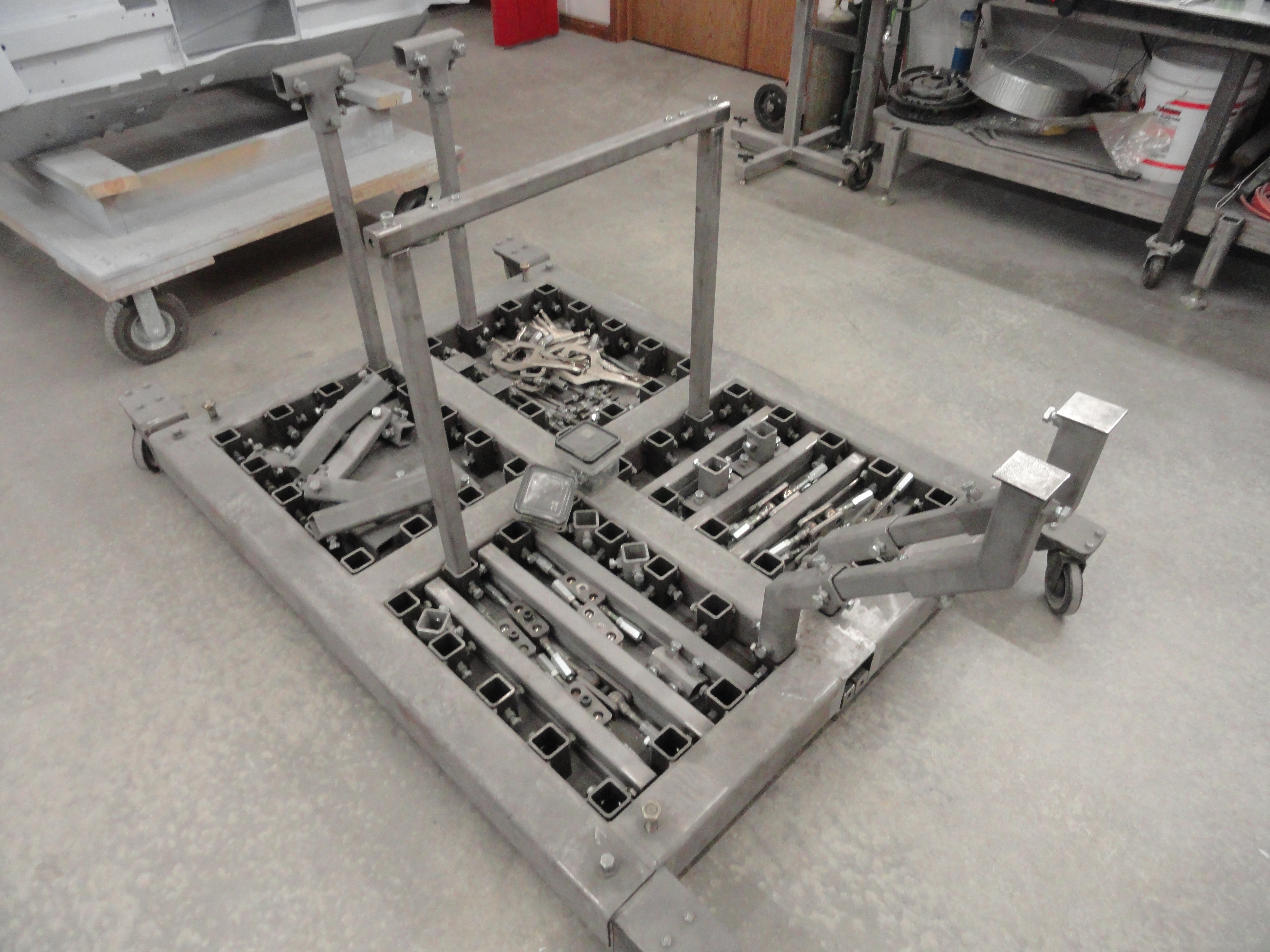
We will make the base cart for this project first. It's VERY heavy by design. If you have a fender or something on the jig and you are long-board sanding or something requiring even, consistent pressure, you don't want this moving on you. This is the main reason we are using such heavy materials. My first thought when building this prototype was that I may end up having to fill these 4 by 4 square tubes with concrete! Thankfully turned out to be totally unnecessary.
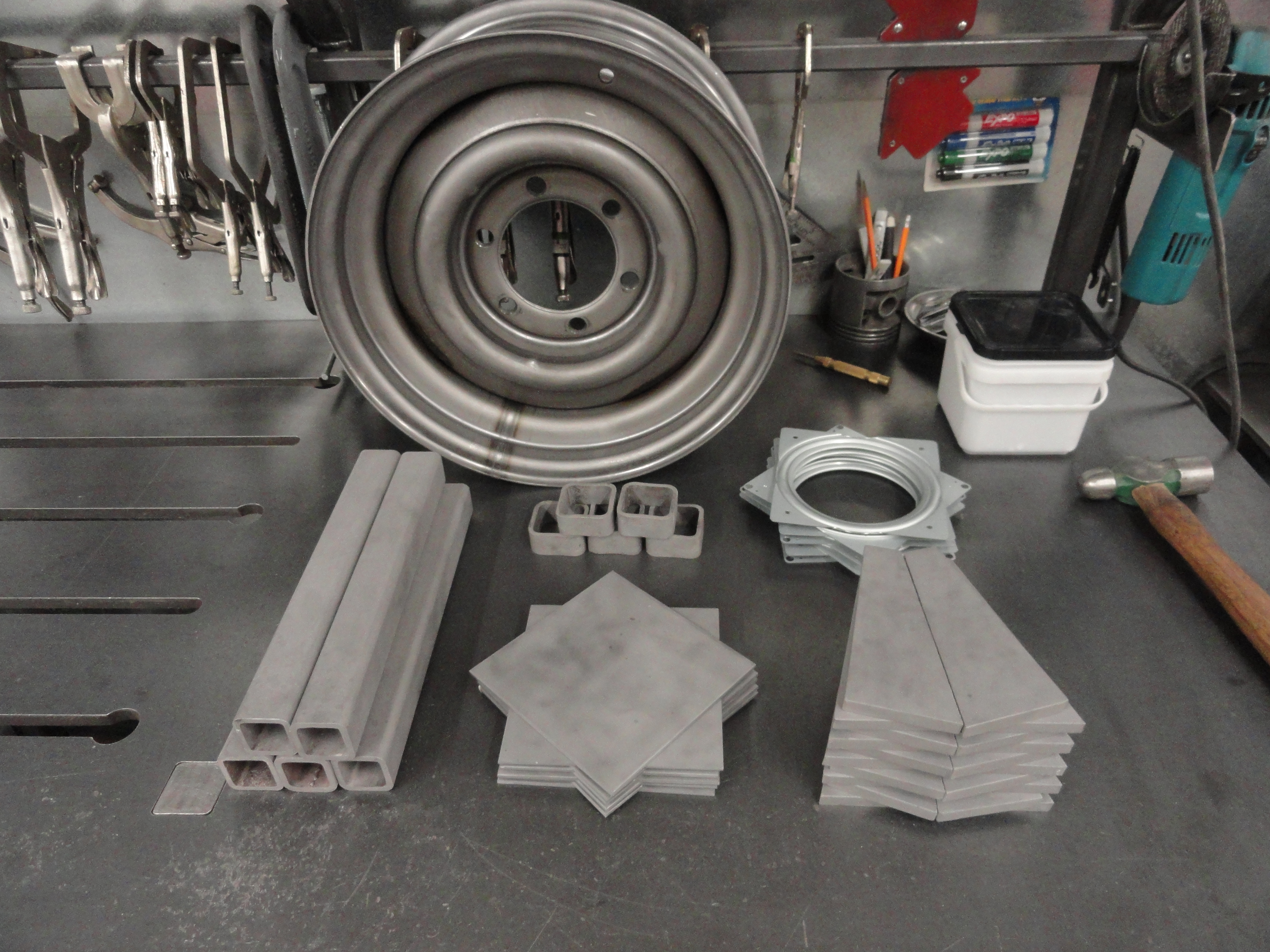
A very nice tool to have in the shop for this project is a Dry Cut Saw. We will be cutting square tubing ad nauseum and as long as you keep oiling the work with Cooking Spray, one blade will last completely through this project. Let's cut the 4" square tubing first. Cut two pieces 74" long, one at 60" long, and 6 pieces 18" long.

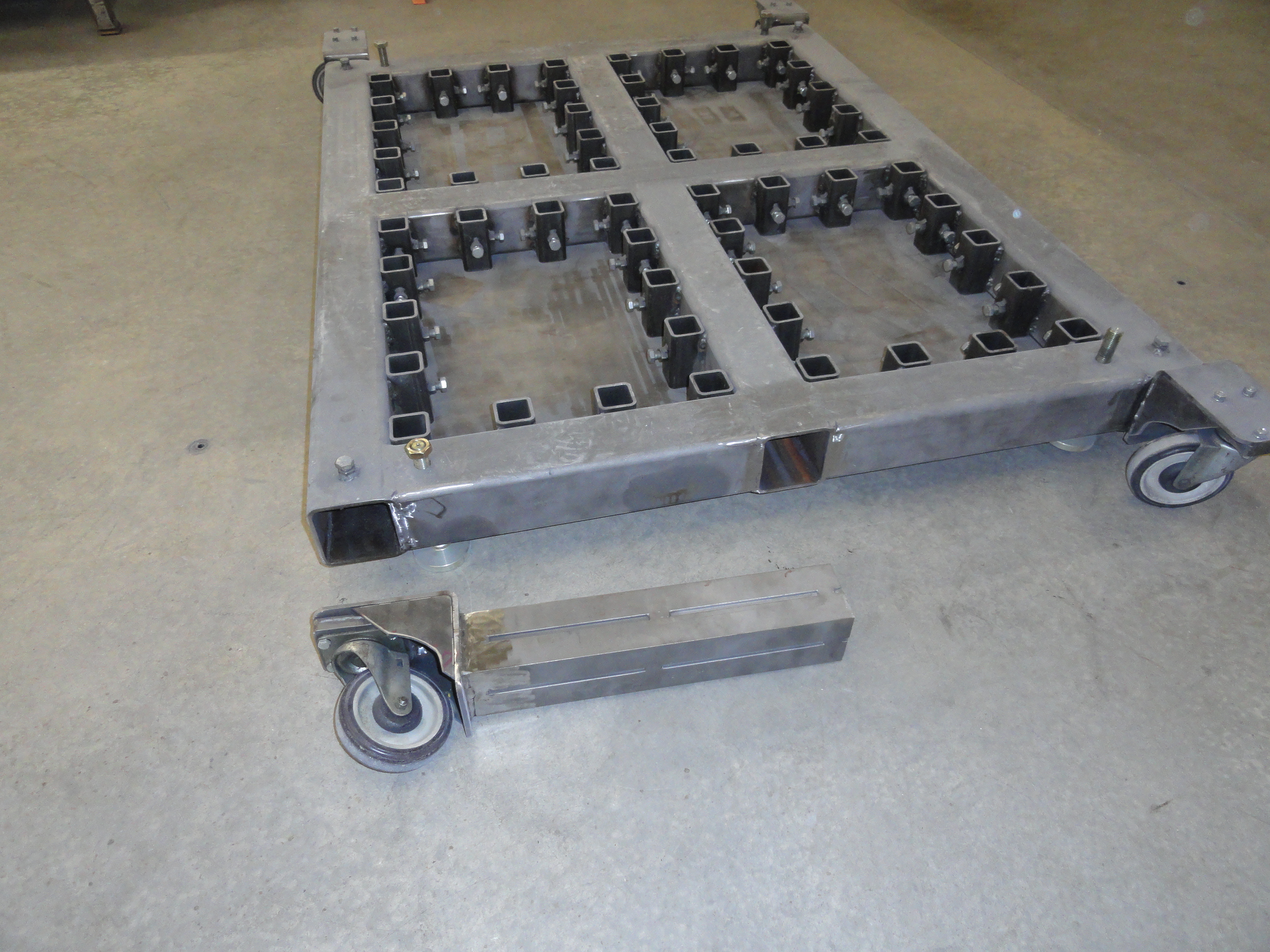
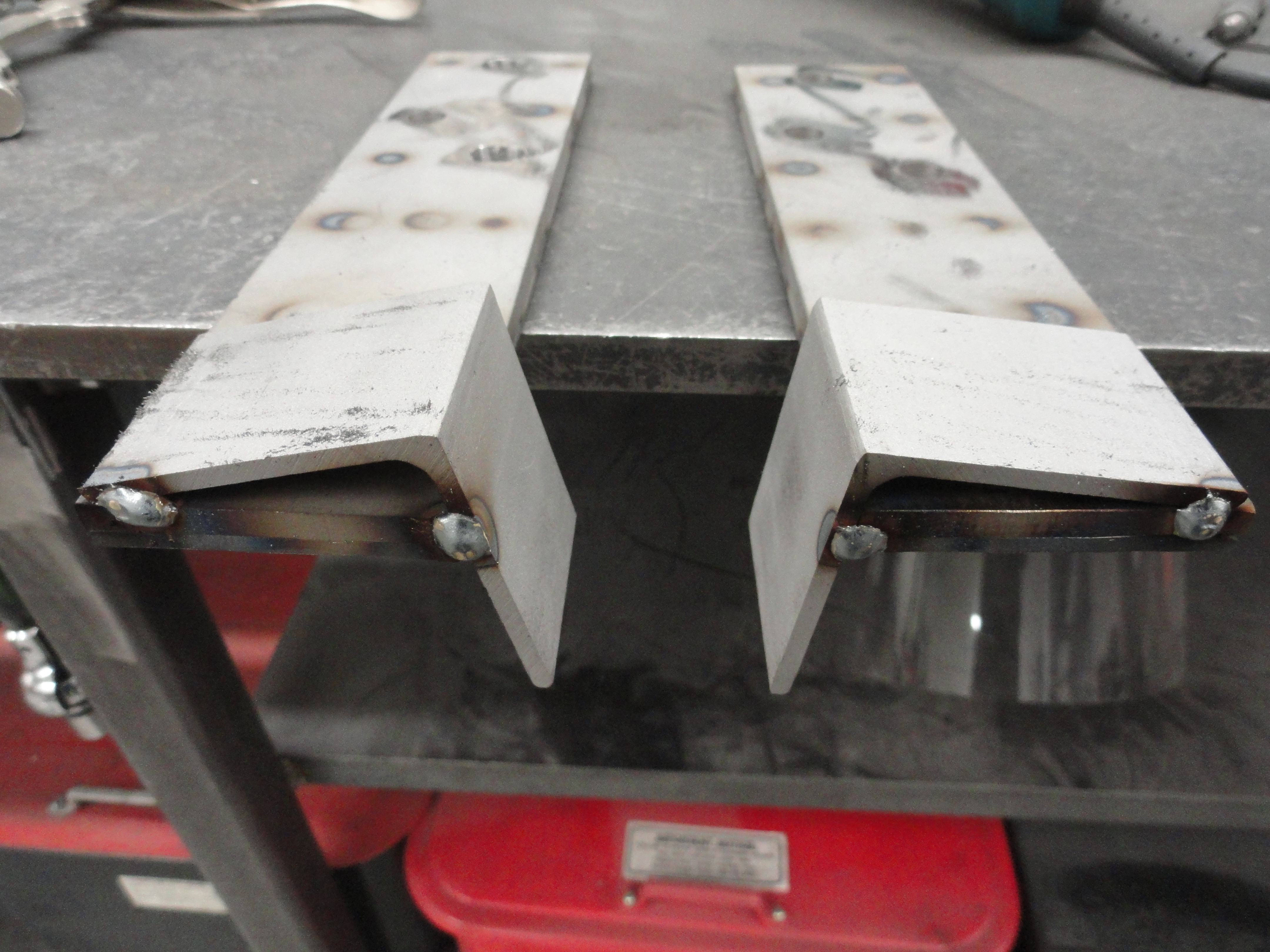
Let's take a look at the picture on the left and pretend the casters are exactly where they are, but are mounted inside the 74" pieces. Now take a look at the picture on the right. What we want to do is make THAT profile in the ends of your 74" pieces. This means keeping the middle 60 inches for the grid, but modifying the last 7 inches on each end with a similar profile to that shown. Since I didn't have you weld it all together first, you can take these two 74" pieces to your bench as well as the 5" casters and reason out the proper profile. You want the casters to turn 360 degrees without problems, but you also want as much structural support on top and on the sides as you can get. The casters should be mounted to the top directly, not the way the prototype has them. This will change the contour enough that it's just better if you reason it out. Once you are sure your casters move freely, and you have mounted them to make sure, remove the casters and continue...
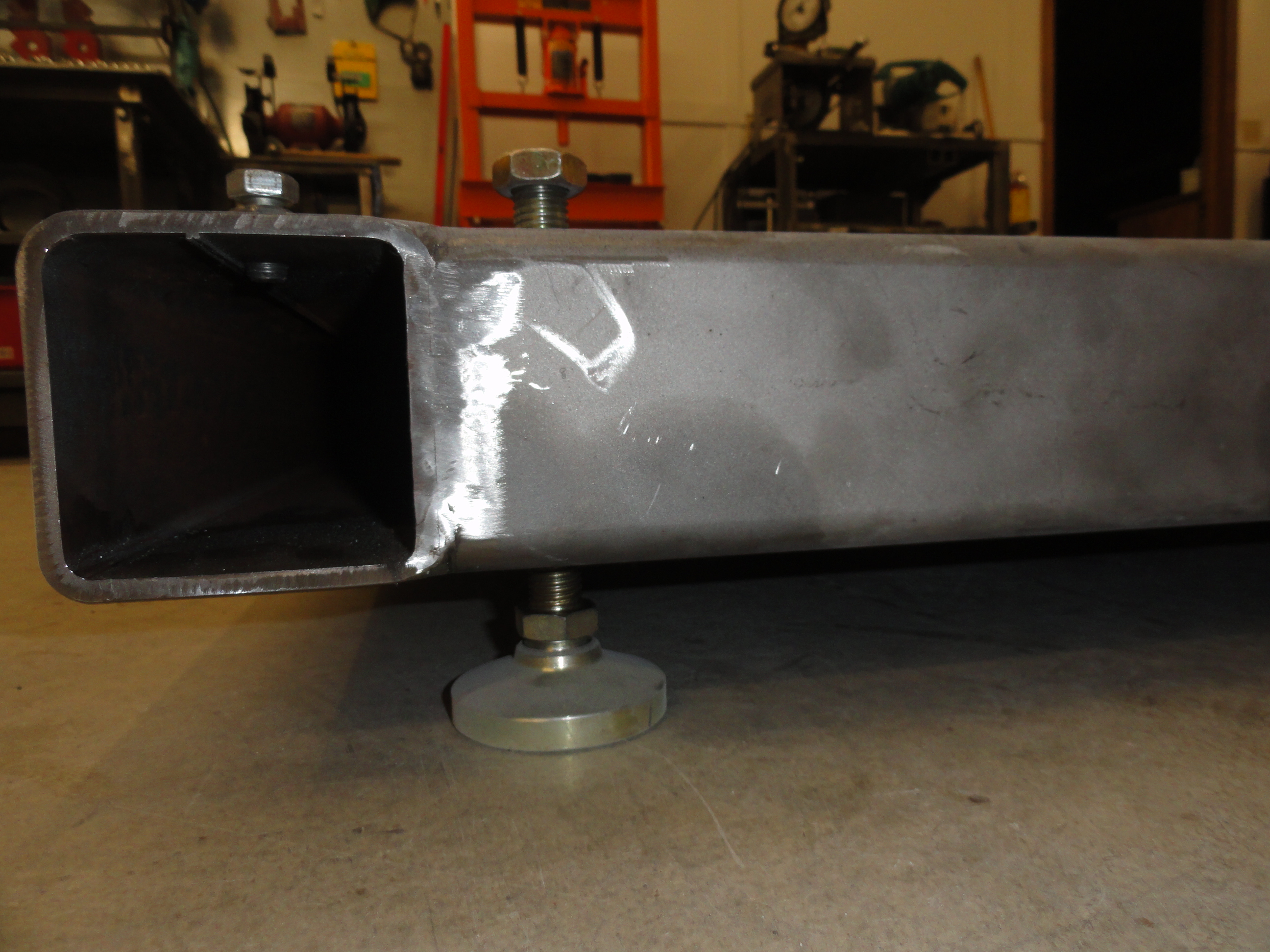
Next we want to drill 4 holes to accommodate the adjustable feet. Drill the appropriate size hole for the leg shaft size. This is about 1 inch in from the
end of the 18" pieces used for the outside of the grid. You will want to weld a weld nut to the bottom of the cart to make the height adjustable, then
weld a nut to the very top so you can take a socket or wrench to turn them in and out. As shown on the left.
Your call as if you want to weld that weld nut on the INSIDE of that 18" piece since it's so close"
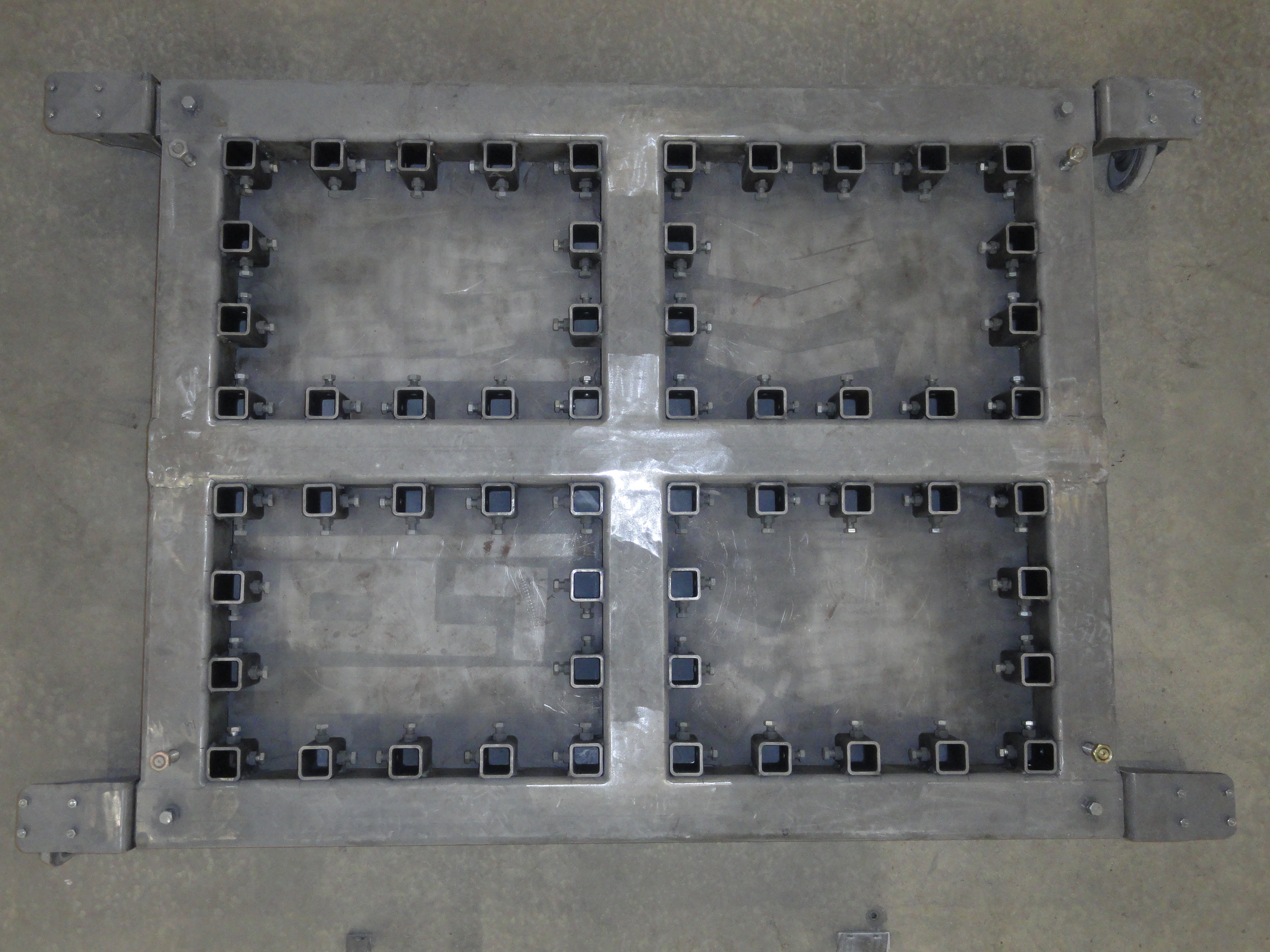
Lay the pieces out on a flat concrete floor so that the 74" ones are on the outside, the 60 incher is in the middle, and the 18" ones where they belong to make a 4 place grid where each of the four inside measurements are exactly 18" by 24". Measure off 7 inches on each end of the 74" ones. Mark them good and understand that we are putting casters inside of those ends, so ensure there is 7 inches, then 60 inches, then 7 inches again in your layout. Like in the picture but not. In the end you will have a 48 by 60 platform (not counting where you modified the corner ends for mounting wheels). Use squares and those 90 degree welding magnets to ensure your grid is 100% straight. Don't assume your saw is cutting straight. Make sure everything is nice and square then weld up the seams in such a way as to not warp the frame.
Next cut out 4 pieces of the 12 gauge plate steel to measure 18" x 24". These are for the floor of the cart. If your measurements are not exactly 18" by 24" you may have to adjust accordingly. We will not fasten them yet, but it's important they just barely fit inside the grid so they can be welded 'just' inside the grids corner surface.
So have we considered every angle here? I certainly hope so. I may have done this before, but I have full confidence you can do it better. If all has gone according to Hoyle.. we have wheels we can install, legs we can raise and lower, and 4 very large holes we can play with. Now it's time to do the boring part. But do NOT think of it that way because it will look bad if you don't do the next steps exactly right...
Every single 2 inch square receiver is 5-1/2 inches apart. So, with a Sharpie, from any corner, measure 1 inch out, then 5.5 inches, then 5.5 inches, etc. in each corner you will have 1 inch left. Works out perfect right? Be sure to put a nice precise mark and then remember the 2 inch receivers will need to be marked for center so they go in the right place. Now let's go and cut 56 pieces of 2 inch square tubing exactly 3-3/4" long. Set yourself up a stop of some sort so they all come out the same. Before welding them in, debur each one and remove the mill scale so you get good clean welds when the time comes, but we aren't there yet.
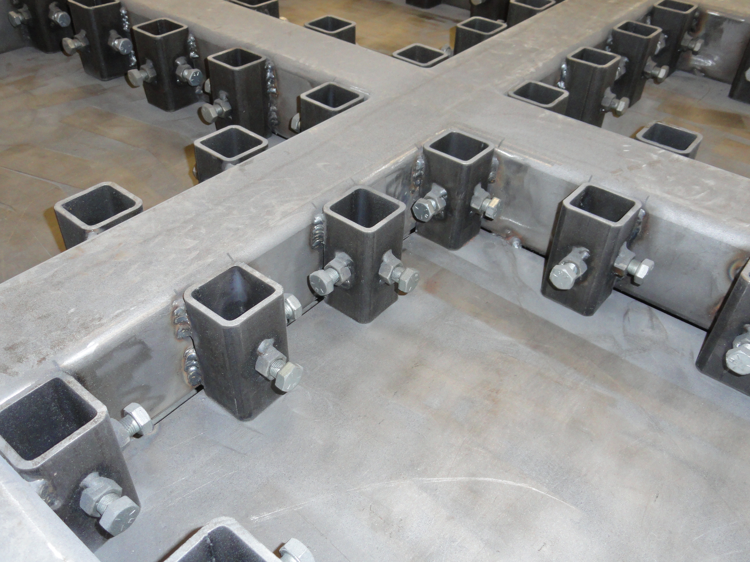
We need to drill these pieces, one at a time to accept the 1/2" inch weld nuts and the 1/2" by 1 inch bolts that will hold down our accessories. Again, use your talents to figure out how to make a stop jig for the drill press so they are all the same. I used my dual plane drill press vise for this. Each 2" by 3-3/4" piece gets two 1/2" holes on adjacent walls in the very center. It doesn't matter which two surfaces since you can turn them anyway you want. Once you have all 112 holes drilled, set up a system for welding the nuts on the sides. To get good welds, you will need to remove the zinc plating on these nuts. I just put them in my blast cabinet and cleaned them up that way. You can also use a flap sanding disc, or whatever works for you. I put a second nut inside and bolted the nut to the side of the piece, then removed the bolt and inside nut once welded. It's a lot of work and very well worth it.
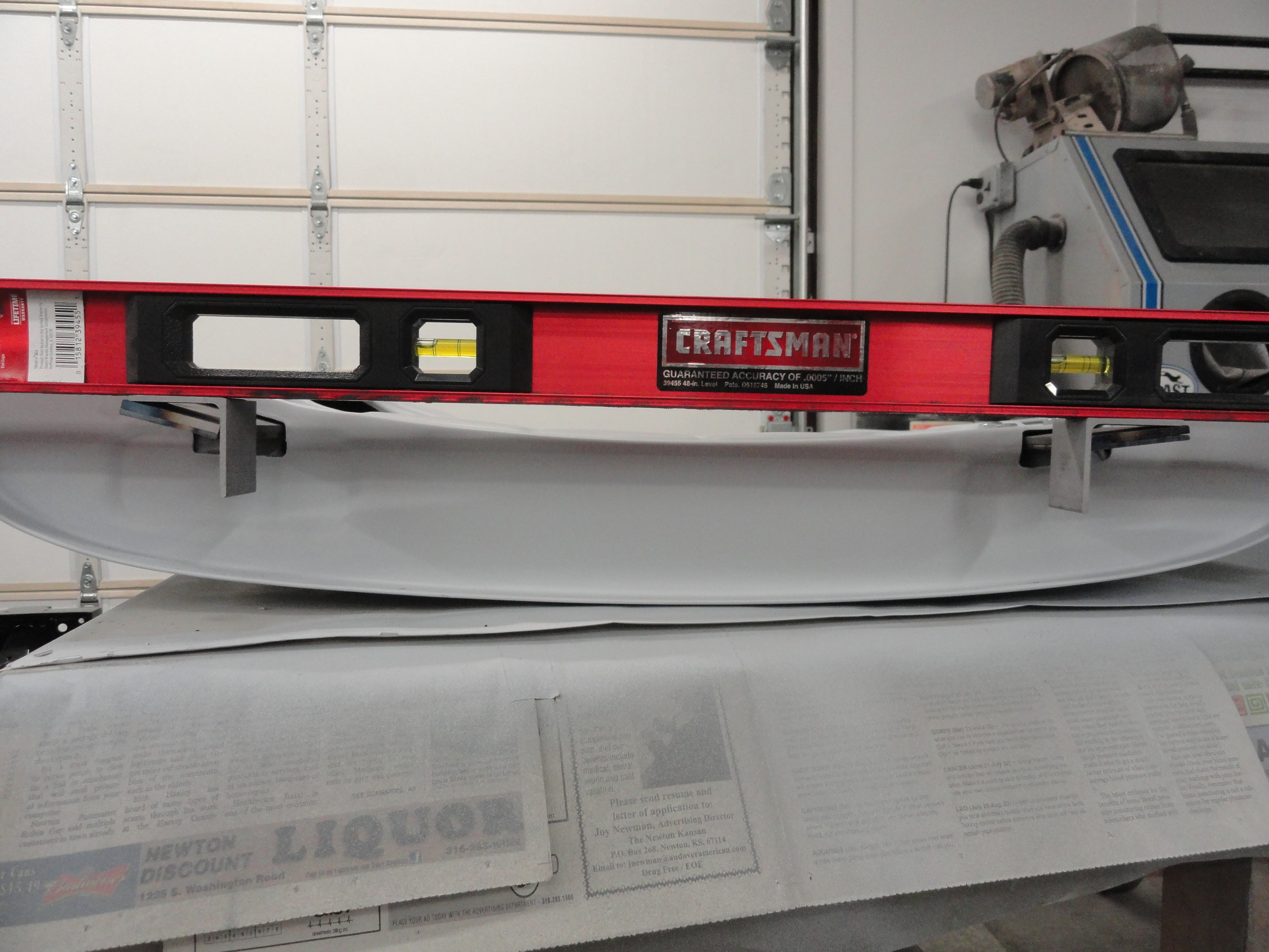
The reason I didn't tell you to weld the floors of the grids in just yet is because I didn't want you yelling at me because that would make it harder to get these 2" by 3-3/4" pieces welded in. My way of thinking is to put the floors in THEN weld in the 2" pieces. Sure it's harder to get the MIG wand in there, but the advantage is, you can set them against the floor solidly so they all measure out much nicer. So, your call, but you can weld the floor in by turning it upside down and use magnets and a 4 foot level to ensure the floor is recessed IN flat with the bottom of the grid. The floors should not be below the grid, rather, flush with the bottom of the grid. This is why you didn't cut those 2 inchers to 4 inches high. Once the floor is welded in, flip it back over to where you previously marked your grid every 5-1/2 inches and prepare to weld the receivers in.
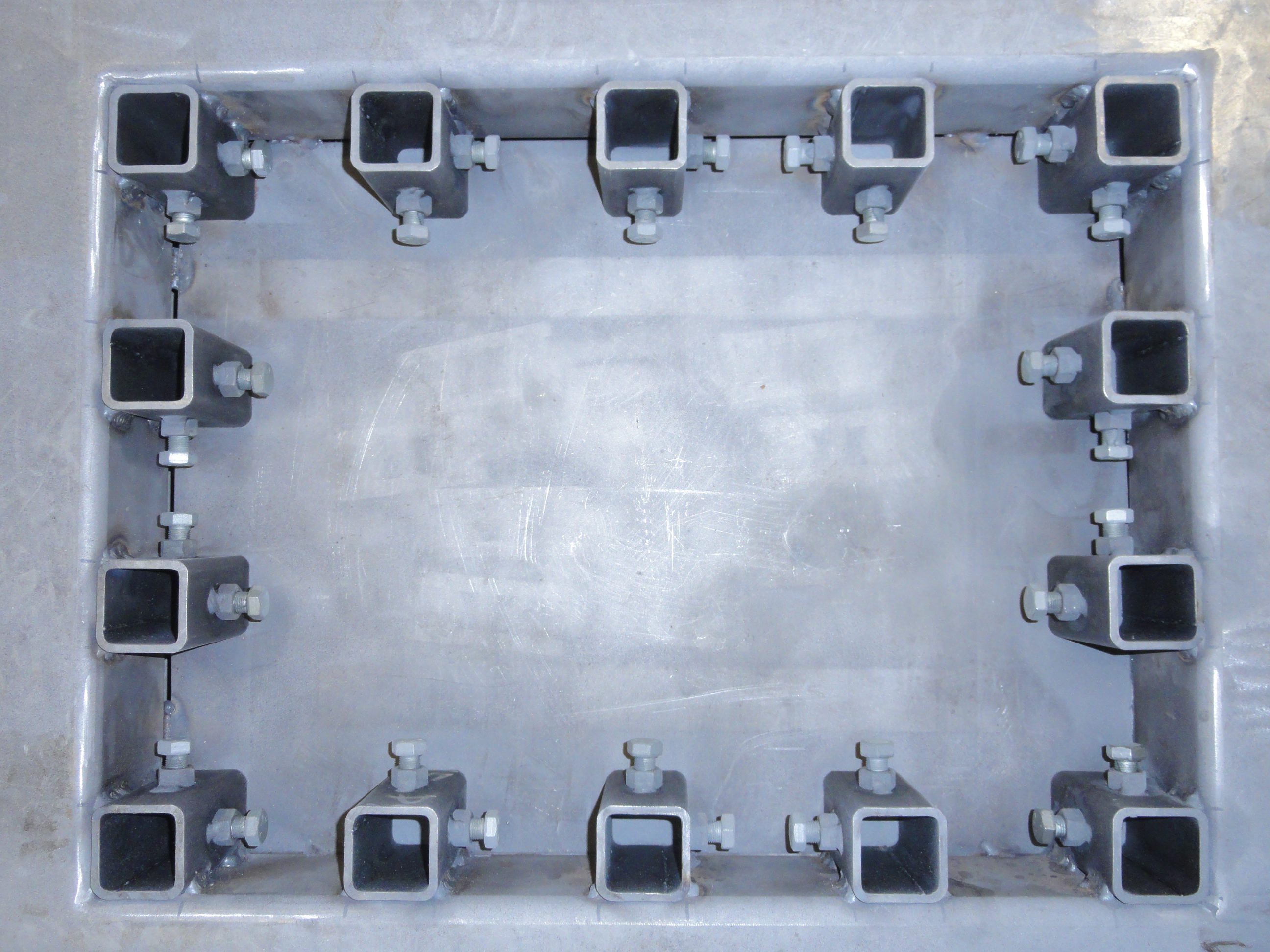
Watch the orientation carefully. There was a method as to which sides the bolt/nut combinations were placed. Of course the corners are a no-brainer, so start with those. Then think about how you will store the 17-1/2 inch sticks we are going to make later and how everything will set into place. If you trust I did it right, just use the picture to the left. Remove the bolts so you can get the Mig in there okay, and make two 3/4" welds on each side, one near the top, the other near the bottom. Good strong welds starting with cleaned metal are essential so you never worry about a broken weld. Once you are done, you can swipe a straight edge across the entire top of the jig and the only protrusions you will have are the 4 adjustable feet.
Install the wheels, the legs and lubricate the moving parts. This includes the 112 bolts. You want to be able to turn each one by hand all the way through their range. I just used white lithium grease. Be aware that any contaminant can be detrimental when that jig is in the paint booth. If all went according to plan, your SuperJig is finished! Congratulations! Now we need to make it useful. The rest of this document will be dedicated to the accessories that make this effort stand out.
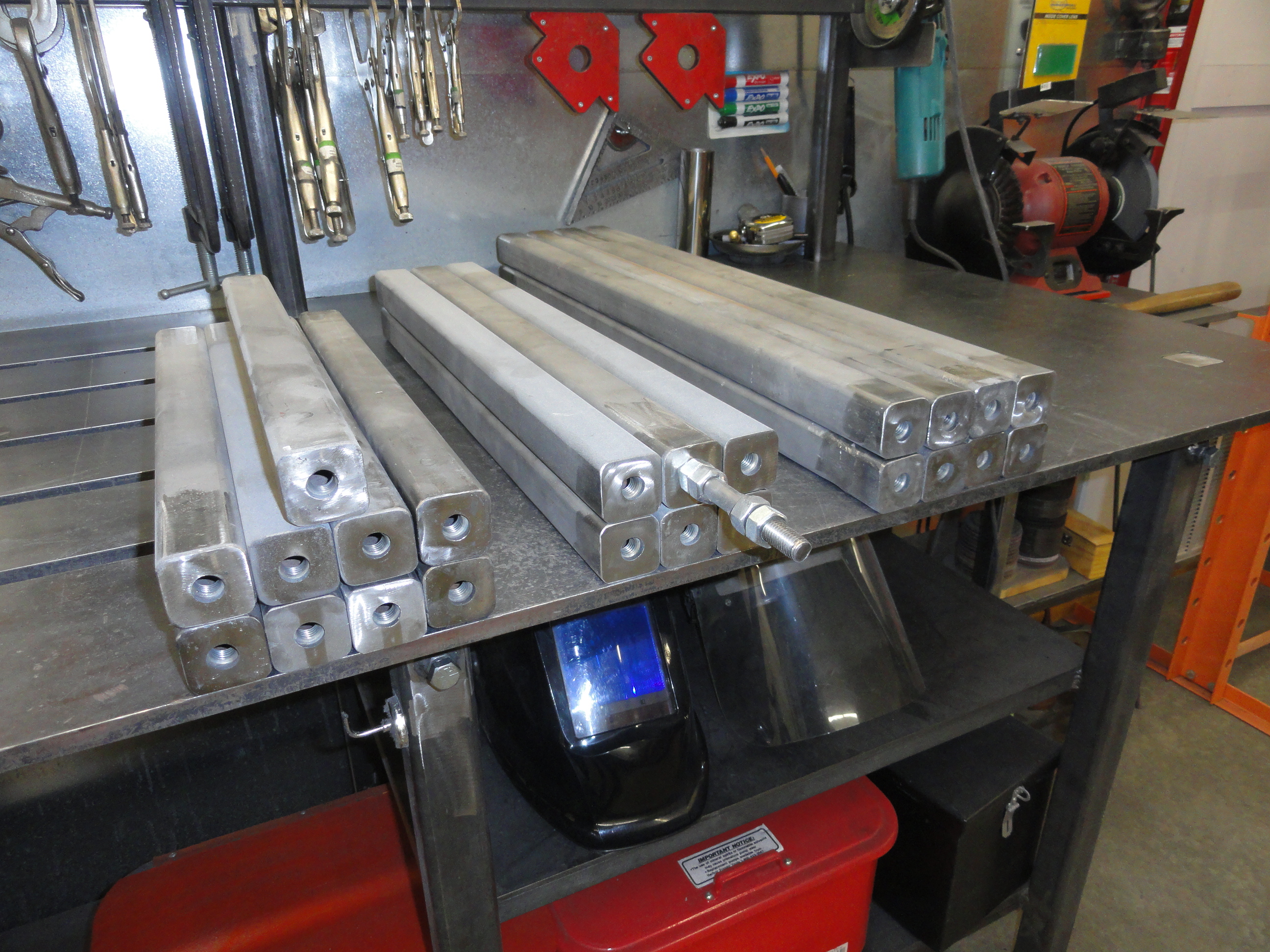
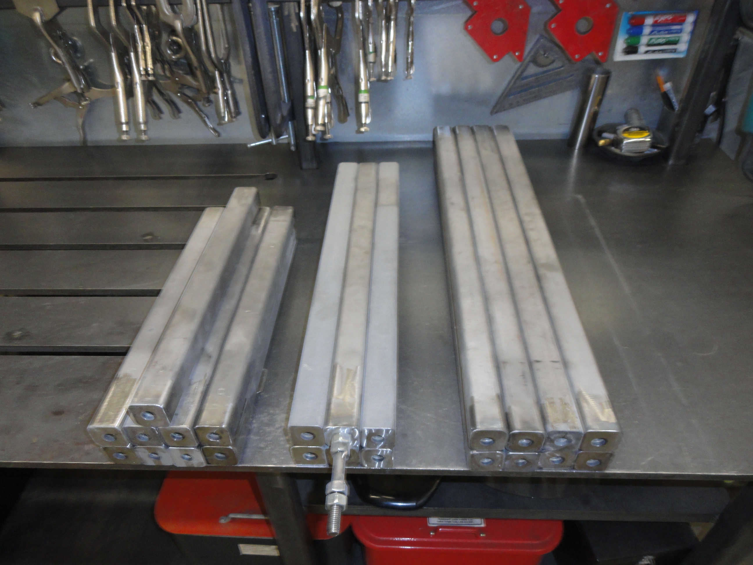
There are a few technologies we will meld into a cohesive system. Let's start this section off with making the 1-1/2" square tubing extensions. I felt making 8 of length 30" was nice because the storage for them is inside the center of the base of the jig. After giving it much thought, the same goes for the 17-1/2" ones. Why 17-1/2? Because they will fit going the 18" way inside the grid. I then felt that I only needed 6 of the middle size 23-1/2 ones. It's your Jig, make however many of each you choose! So, in review, 3 sizes of 1-1/2" square tubing. 8 of the 30 inchers, 6 of the 23-1/2 inchers, 8 of the 17-1/2 inchers.

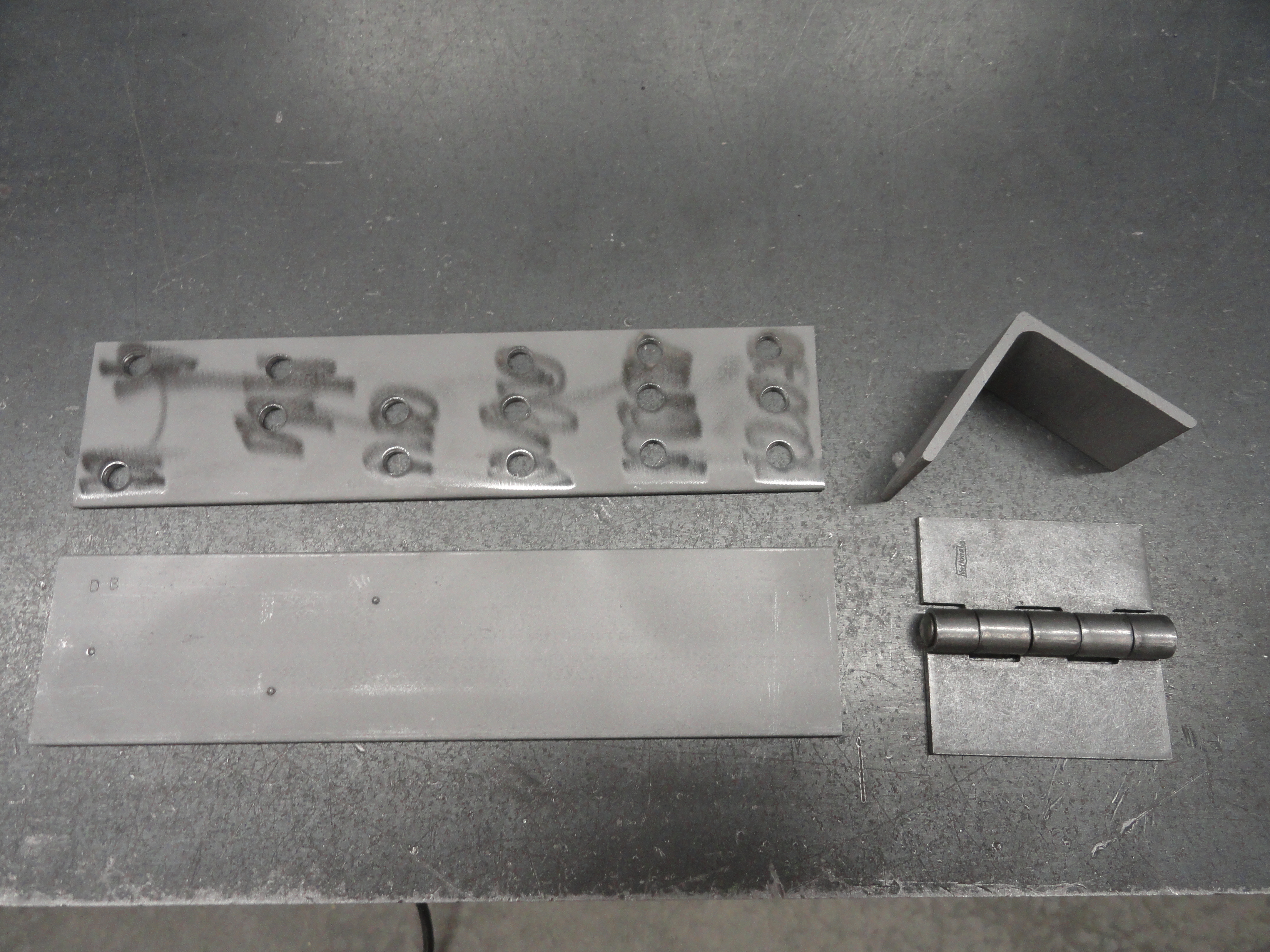
We are not going to just cut those sizes and be done with it, to make this jig as useful as it is, we need to add weld nuts on each end. This way, we can extend these pieces and do a whole bunch of cool things with them. So we have 22 ends that we need weld nuts for if you go with the quantity of 1-1/2 inchers stated above. Go ahead and cut your 1-1/2 inchers at your desired lengths, then make as many weld nut plates as you need. The weld nuts are 1/2" coarse thread. The way I did it was, I cut out 30 (in case I decided I needed more) 1-1/4" square pieces of plate steel out of 12 gauge material. I then marked each hole carefully in the center of that piece. You can make an X from corner to corner on these square pieces and get them perfectly in the center everytime. Drill the half inch holes, then bolt a nut to them to secure the nut in the right place for welding. Don't forget to clean the Zinc plating off the nuts or you risk poor welds due to contamination. Shown on the right.
Once you have all of your 1-1/4" square pieces made, the idea is to weld them inside of each end so as not to add to the length. You may have to grind off the corners a bit to get them to fit. Once you can set them into place, use a magnet to keep them in place for tack welding, then finish welding. Grind off any excess weld to make the ends smooth. Do this for all of your pieces, then you can move on to the next step.
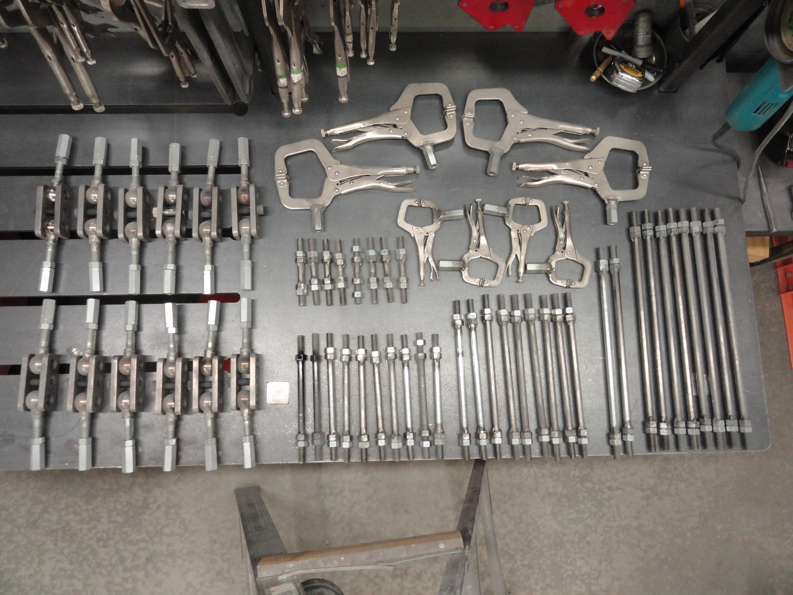
Now we need some accessories to take advantage of this new system. I am at a disadvantage when it comes to Lathe work. I don't have one, so I farmed out the following to my local welding shop. We need 8 each of the following size 1/2" solid round stock threaded on each end: 17-1/2", 15", 12", 9", and 5". I had them put threads on 1-1/2" of the stock on each end. Coarse threads are needed for the weld nuts you put in each end of your 1-1/2" square tubing pieces. I then threaded nuts all the way down to the bottom of each one and welded them in place. This is a much more secure way of tightening things down. To make them easier to use, I just threaded a second nut on each one so I am not looking for nuts when I need them.
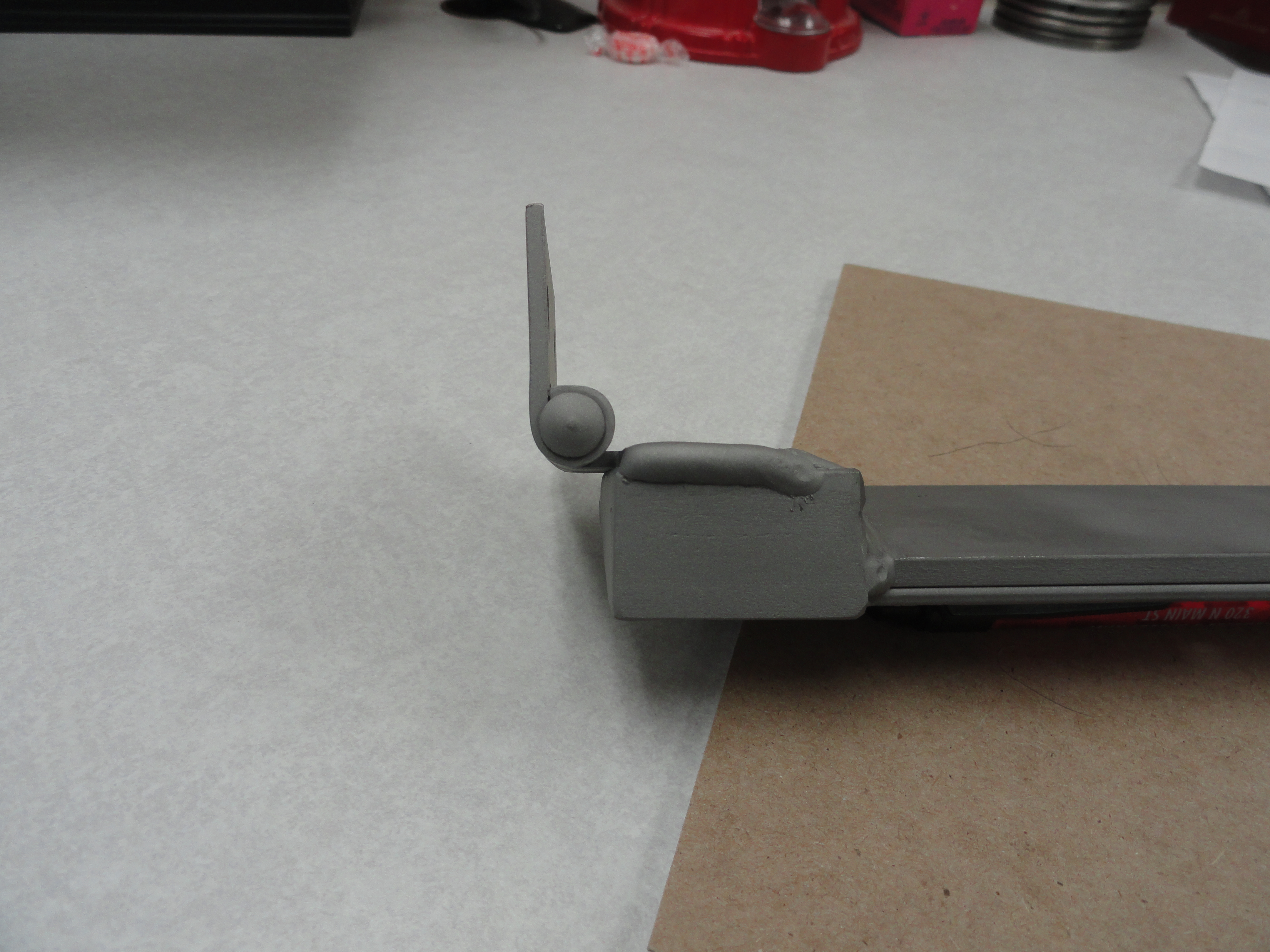
Now we have extensions that we can use for just about anything. The 1/2" rod is plenty stout for most automotive needs. Let's make them even more useful. I got my Vise Grips from Harbor Freight. Reason for not using good ones is because we are going to weld a long 1-1/2" Coupling Nut to the vise grip. Since the Vise Grips are Zinc plated, welding will ruin the finish on the Vise Grip. I just couldn't see doing that to really good ones! So, weld these coupling nuts as shown to the Vise grip. Now we have a method of clamping, but what we don't yet have is a method of turning our work to any desired direction. We need to make turnbuckles for this purpose.
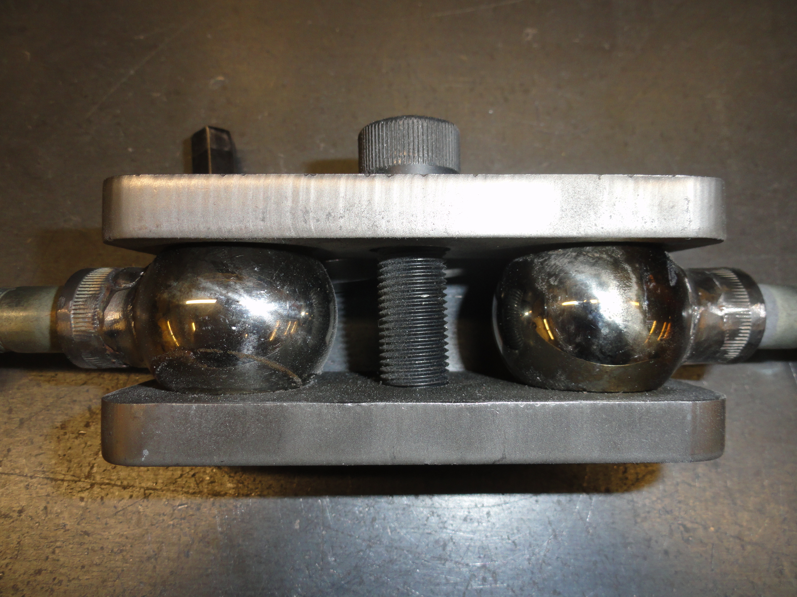
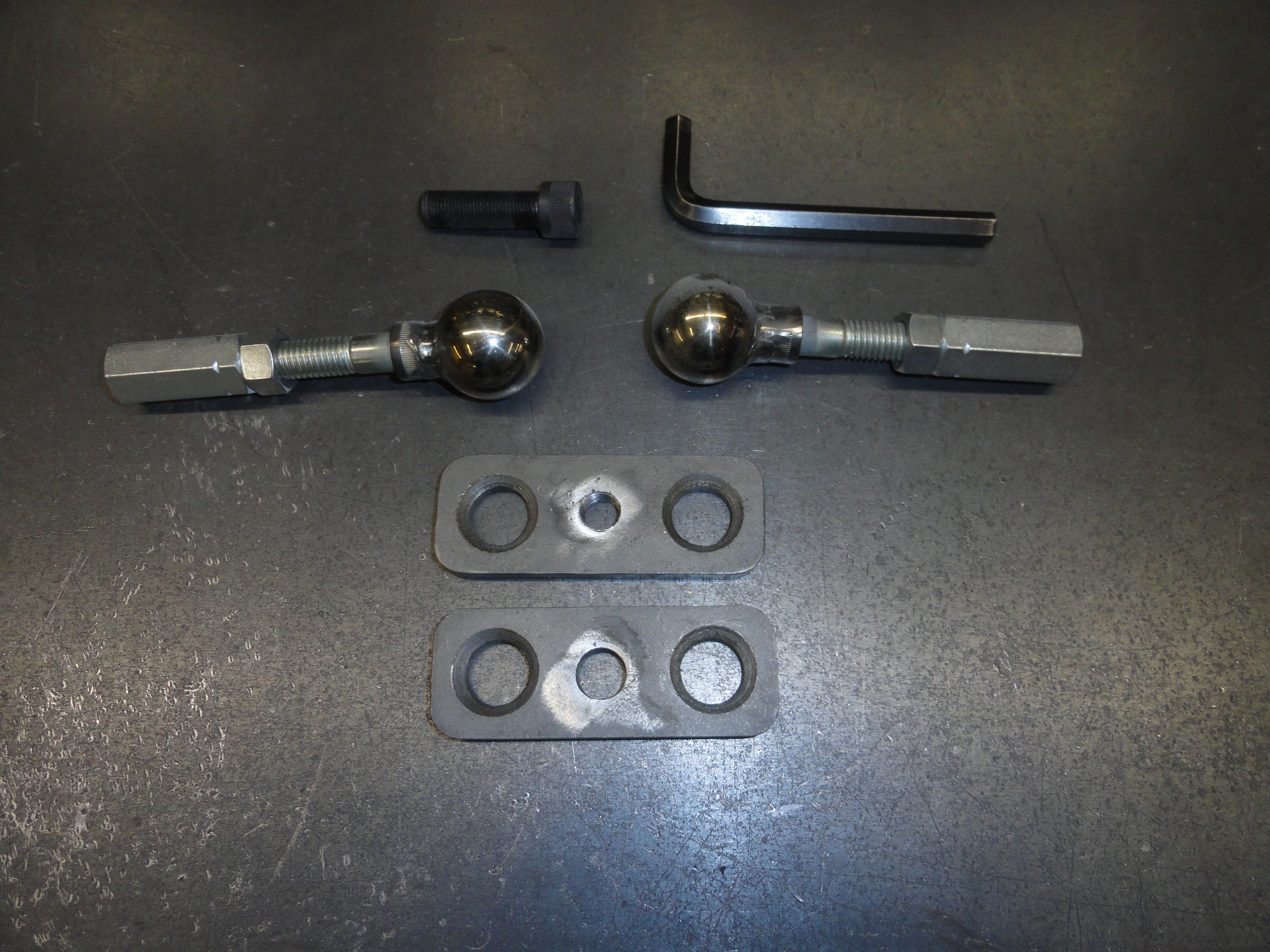
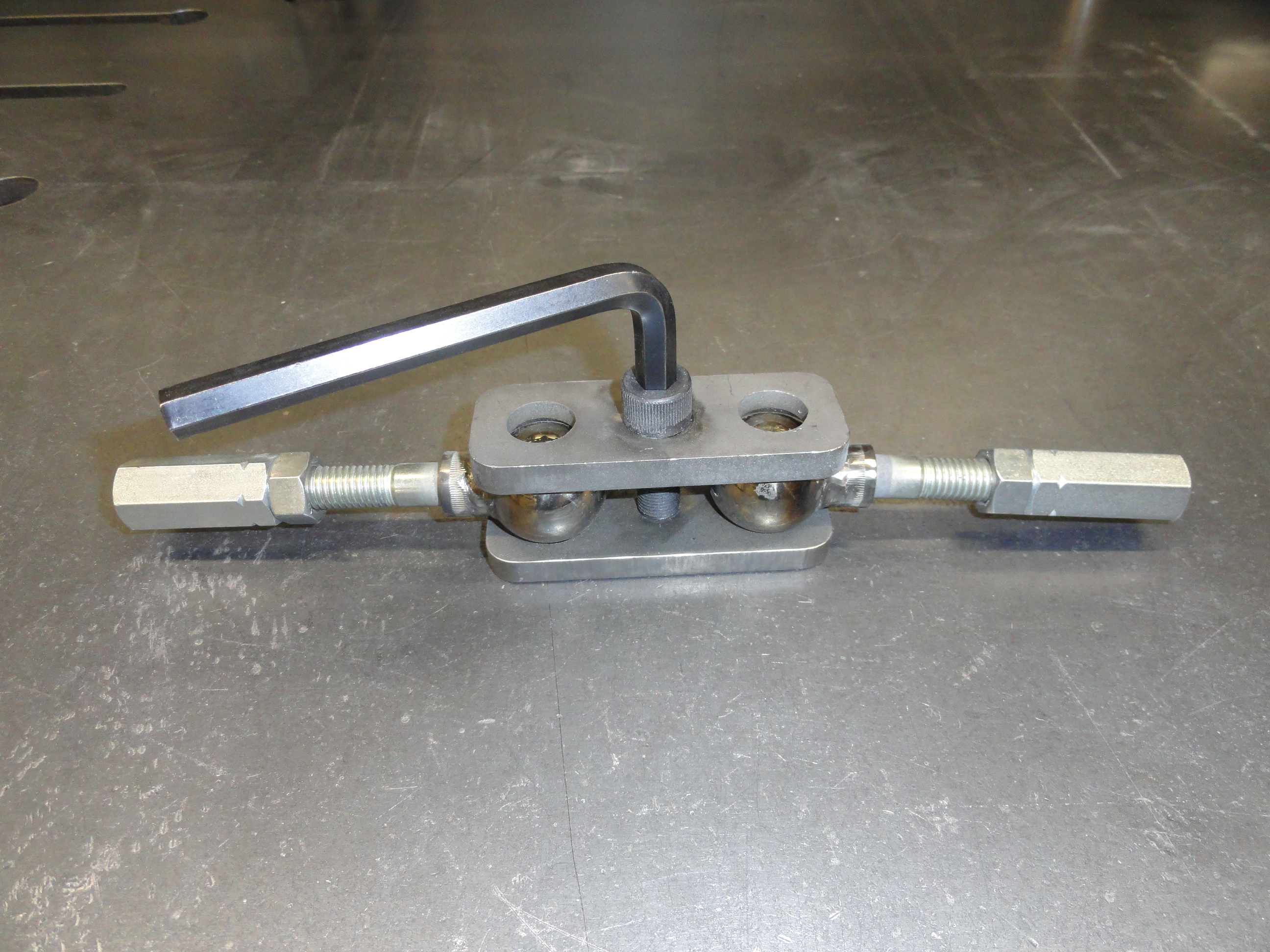
I got this idea from a YouTube video from Lazze's MetalWorking. What a great idea! Although this isn't an easy thing to get right, it has proved to really enhance this effort. Thanks Lazze! But it IS hard to get right. There are two plates that we will sandwich two ball bearing assemblies into. So, cut your plates out of 3/8" plate steel to 4 inches by 1-1/2 inches. In the very center of HALF of them, drill them out to 33/64". This is just an adequate through-hole for the 1/2" fine thread Allen bolt to go through. On the other half, drill them to 29/64" for tapping a 1/2" fine thread(24) hole to accept the Allen Bolt. I made about 20 of these turnbuckles because I can see a need for them around the shop. The smart thing to do before drilling anything is realize how absolutely essential these holes being EXACTLY across from each other are. Rather than drilling them one at a time, drill them in sets to the smallest hole size, in this case 29/64", then re-drill the other half for the bigger size. Install the Allen Bolt and cinch the two down together tightly.
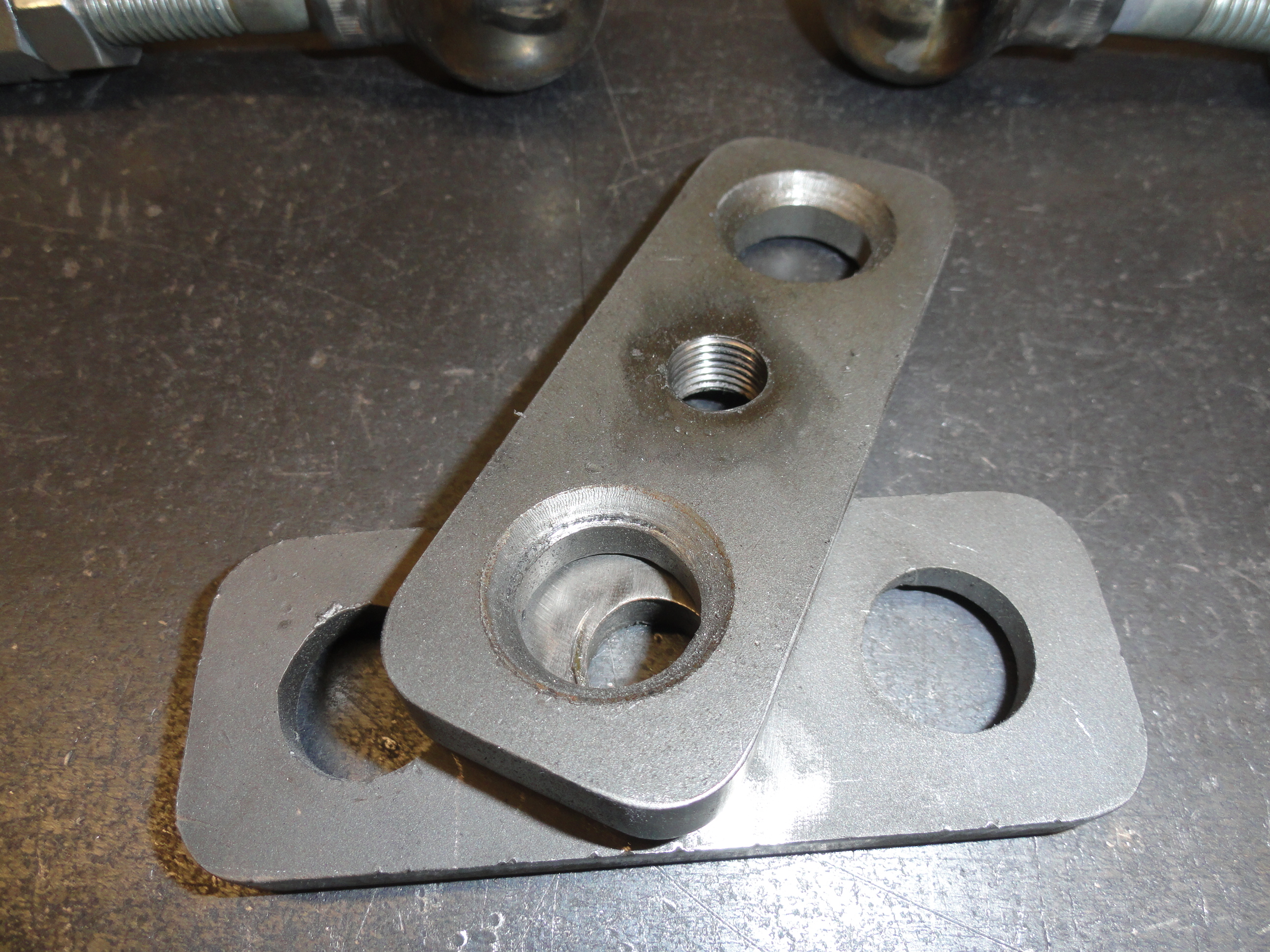
Once again, precision is so important here. Mark your next two holes for drilling 3/4" from each end. Your mark will represent the center of the hole. Drill the two holes using a 3/4" drill bit making absolutely sure the two pieces do not move AT ALL. Since they are drilled together WITH the center Allen Bolt in, the system will work great in the end. Now, with a 1-1/2" Chamfer Bit such as the Keo - 55433 - Countersink Head Diameter(Inch): 1-1/2 very carefully put about a 1/8" deep chamfer on the inside only. This is to make the ball bearings work much more efficiently. If you don't want to spend about $150 for this bit, it may be better to outsource this step to a local machine shop. It's an important step to make sure the ball bearing has enough contact with the two plates to work efficiently.

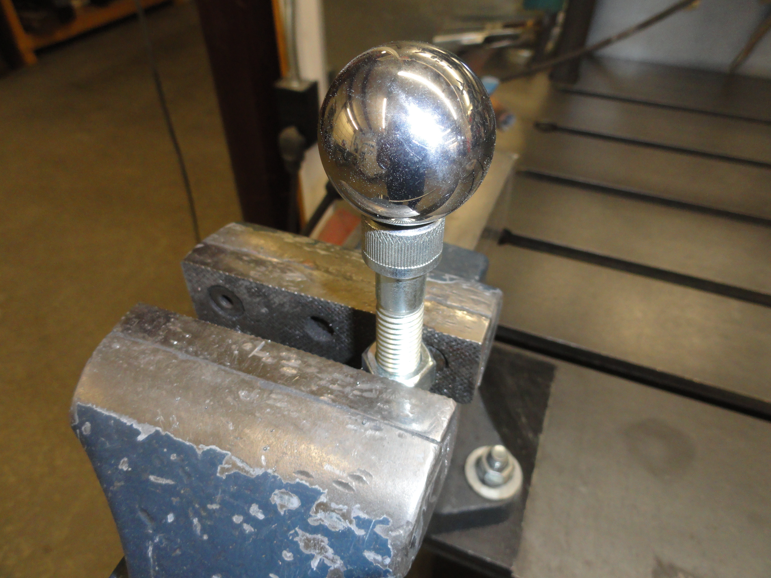
The ball bearings to use are the carbon steel ones with a hardening factor of about grade 5. The diameter is 1-3/8". Since you have to weld these ball bearings to the head of a bolt, we really need the least hardened HARDENED steel balls for this. I used an Allen Head 1/2" Coarse Thread bolt for this. The Allen head allows for the ball to sit centered in it for welding a bit better than other styles of bolt heads. I used my bench vise for this. I threaded two nuts on the bolt and clamped them in the vise with the bolt pointing up, placed the steel ball on top, then used a propane torch to preheat the hardened ball. This gives you a bit more insurance that your 220 Mig Welder on its Hottest setting will penetrate good enough for the weld to hold. I then pushed down on it using a piece of 3/4" pipe to keep the tack welds from moving the ball, then tacked on two sides before finish welding. I am very happy so far with the results. I put a coarse thread nut on each end so that when I use them, I don't have to look for them.
So those turnbuckles are not easy for a guy with a home shop. I know a lot of you don't have a 220 Mig. Sometimes it's just worth it to get your local welding or machine shop involved. By making these turnbuckles, you just made it possible to put the accessories you have already made together in such a way to make any configuration you want. It is no longer the equipment that is lacking. Just your imagination. But we are not done yet! Now we need to make some basic connection pieces for that 1-1/2" square tubing. This will eliminate the concern that 1/2" round stock isn't stout enough for some applications.
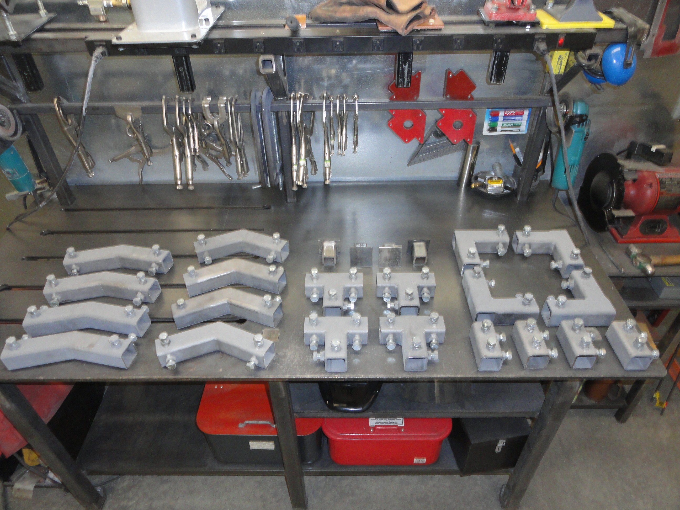
Check out the picture on the right. We need to do that! This will enable you to put together some VERY strong structures used for just about anything. The only problem with this entire SuperJig is how many of each thing do you need? In the case of these pieces, I feel the very least is 4 of each.
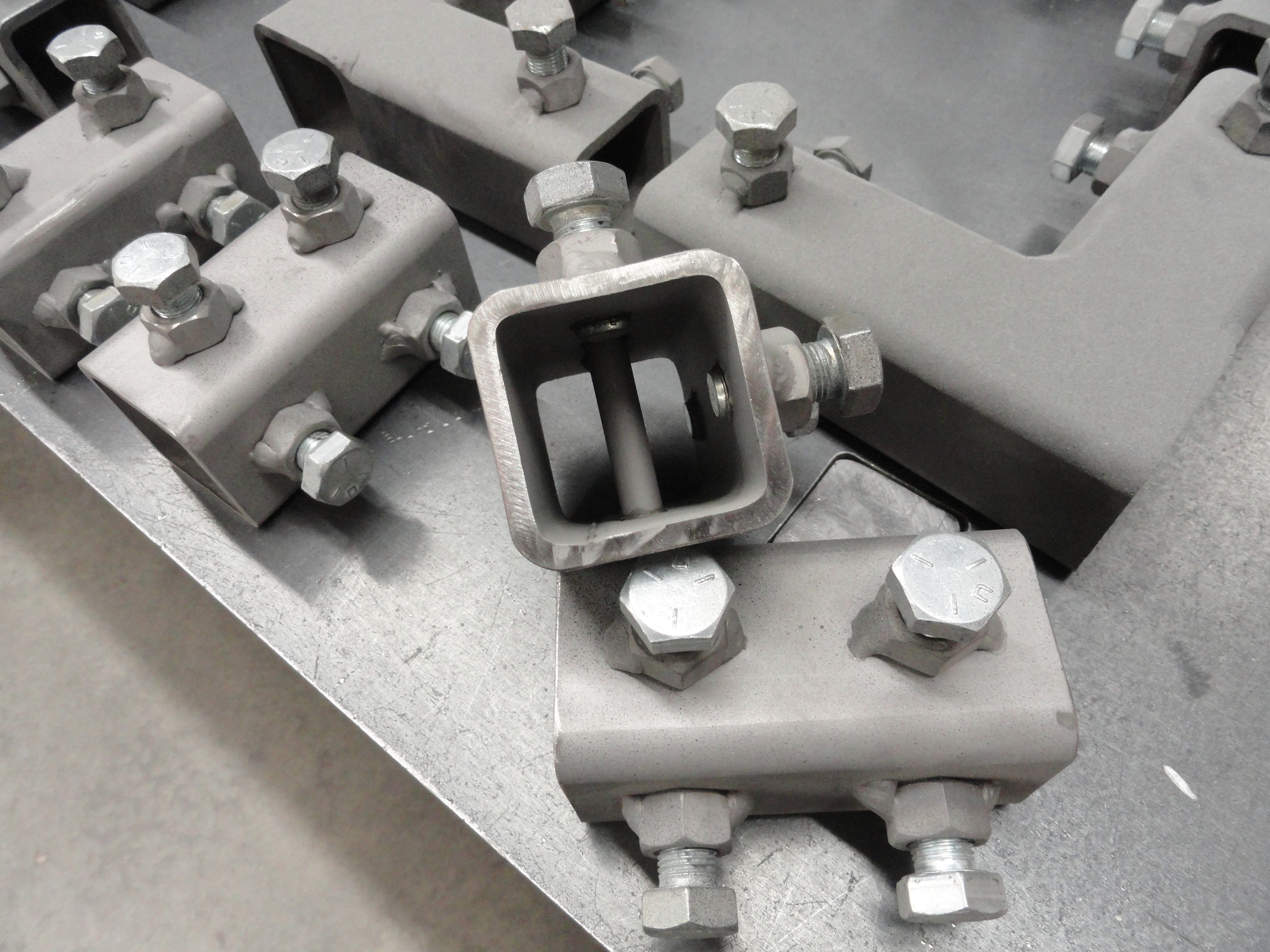
So the 22 and 45 degree couplers use 6 inch sides. It's not 12 inches total due to the angle. The 90 degree coupler is 6 inches on one side, 4 inches on the other. The T couplers are 6 inches across, 4 inches for the middle member. The straight couplers are 4 inches with a 3/8" round stock welded into the center. You need a stop in the center of a coupler so you can ensure both sides are supported equally. The caps are used to dress up the end of something. Not real necessary, but I was into the moment! Each piece uses the signature dual bolt and weld nut system for keeping everything tight. If you got this far, I do not need to describe how to do it. Take your time and try to have at least as much fun as I did!
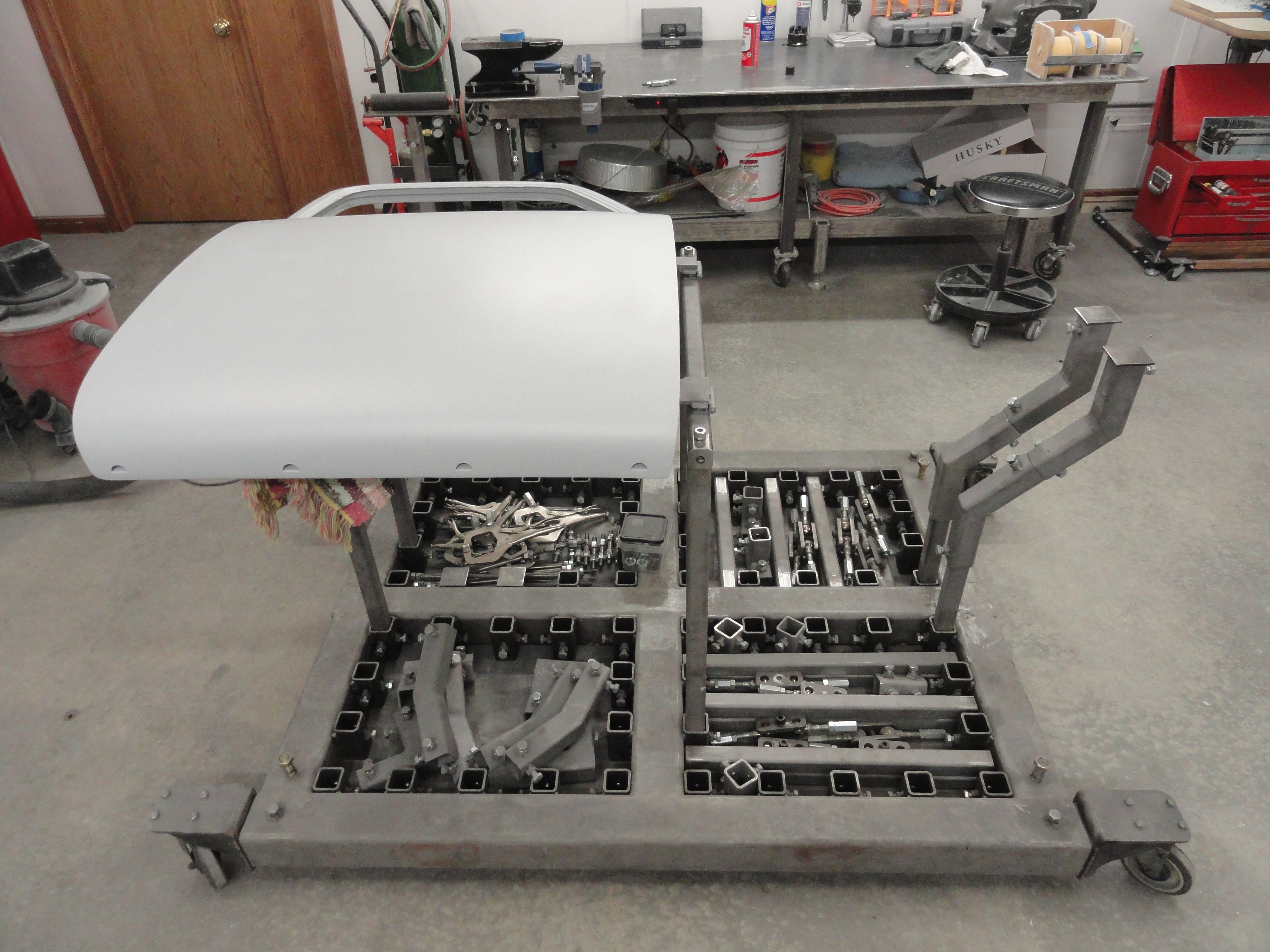
This will describe how to put a 1947-1955 Door on the SuperJig. If you have a different vehicle, the idea will be the same. We will start by making a center hinge point out of parts that are already a part of the SuperJig. You will need 3 of the 30 inch long pieces with the 1/2-18 holes on the ends. Place two of them upright as shown, then the top one will be modified to support hinges and bolting to the other two 30 inchers. Start with the holes needed to bolt to the uprights. These will be two 1/2" holes spaced the distance across. Tighten down tightly the two upright pieces, then measure the distance across them to the center points of the existing holes. Place that distance in the middle of your 30 inch cross piece. If your dimensions are exactly like mine, the distance across was 27.5 inches to the center of the hole, leaving me to mark 1-1/4" in from the end of the 30 inches. Drill the one on each end of 1/2" hole all the way through. Using two Allen Head screws left over from the ball bearing project, (1-3/4 x 1/2 x 18), bolt down the cross piece. If you have trouble getting things to line up, re-drill the bottom holes to 5/8".
To measure where your door hinges will meet the top support, measure from the center of the top hinge opening to the center of the bottom hinge opening. For me that was 19-3/4". Again, place that measurement in the center of the 30 inches. In my case that was 5-1/16" from each end. Mark the center of two, 2-1/2" x 1" un-plated hinges. (the one inch measurement is one side of the hinge). On one side with the hinge facing up, mark 1/2" down (the center of the hinge) and 1/2" from each end. Center punch that junction for two 21/64" holes. We only need the holes on one side since we will be welding them to the actual door hinge. Drill the two holes in two hinges in the exact same place. Very important these holes in the hinges align perfectly with each other. Measure precisely. NOTE: The drivers side and passengers side doors are not the same, so you will need a total of 4 sets of everything before you can mount both doors to your jig. For time savings, you can go ahead and drill all four hinges and set two of them aside.
With the holes drilled, mark the top of your cross piece and drill 21/64" holes from top to bottom on the cross piece to fasten down the hinges. I marked in the very center of the width of the cross piece to keep things uniform. I then used 5/16 x 1-3/4" hex head bolts to fasten the hinges to the cross piece. With your hinges dangling from the cross piece, we can move on to the door hinge parts that will be welded to them.
Find a total of four flat bars that are 8-1/2" long by 5/16" thick. I couldn't find such a thing so I did it the hard way and got a 1/4 x 48" strip and then another 1/16 x 48" and sandwiched them together. You can't just live with the 1/4" because you will ruin the inside of your door. The width of your strip MUST be 5/16". If you are using other types of doors, check this out before making the strips by measuring the thickness of an actual door hinge. I just drilled a series of spot weld holes at different intervals to keep these two pieces together. With four 8-1/2" long by 5/16" thick strips, set two of them aside and lets concentrate on one door at a time from here. Place a bar inside the TOP door hinge cavity. If you can't get it in far enough to make that end hole, do some rounding of the bottom of it to get it to fully engage. Once your bar is flush against the stop, yet with enough meat to get a hole drilled there, mark all three holes very precisely for the three 3/8" bolts that will hold it in place. (I had a full 1/4" between the top of the bar and the beginning of the hole.)Be sure your flat bar rides in the center of the opening and not to one side before marking. Center punch and drill to 13/32" to give yourself enough slop to be able to adjust them slightly. Bolt in place on the door with 3/8x24 bolts with flat washers to protect the area. Do the same on the bottom bar.
Once you have both bars bolted in properly, measure from the edge of the door opening to the exposed end of the flat bar. Measure 3-1/4 inches down (that much should be protruding) and mark it. Do the same for both. You will need to cut the excess off so that there is 3-1/4" protruding from the hinge opening on each bar. Once the excess is cut off, bolt them back in place for the next step.
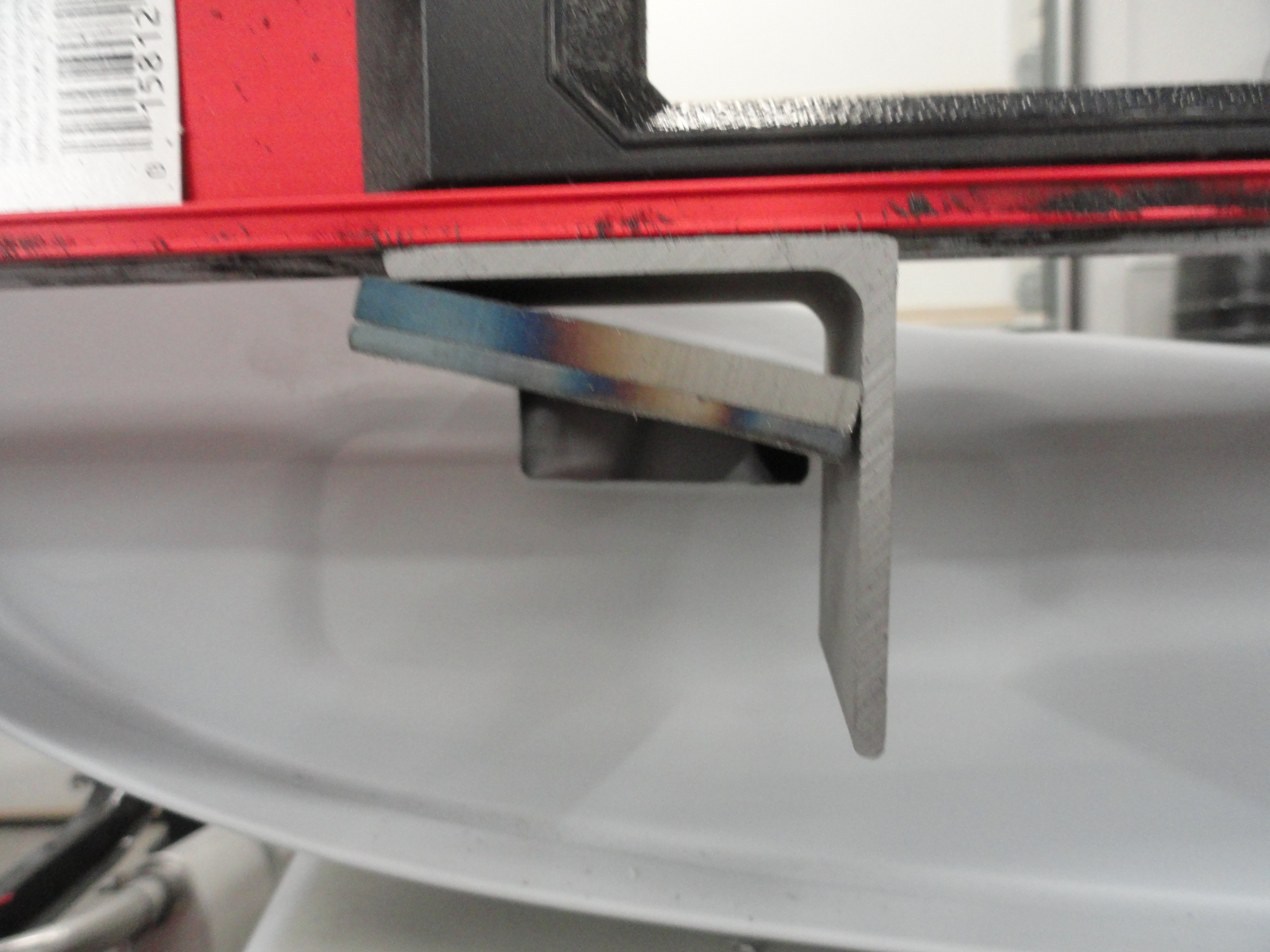
As you can see, the flat bars are not straight across from each other. They are angled differently. Get yourself some 2 inch angle iron (8 inches of it will do) and cut 4 pieces 1-1/2" long. This will act as our equalizer. With a MAGNETIC 48" straight edge, set the straight edge magnetic side down across the two bars. place your angle iron piece as shown so that the magnet is holding up the angle iron properly for a flat surface. Tack weld your two pieces of angle iron in place, then remove the bar from the doors for final welding. I used alot of weld and really closed it all up. I didn't want to leave any cavities that can create more places for rust, or dirt particles to settle. That is an issue during final paint! Once you have your flat bars flat to each other, bolt them back on the door, recheck your work, and if you are happy with it, we can go ahead and get the hinges ready for welding to the flat bar.

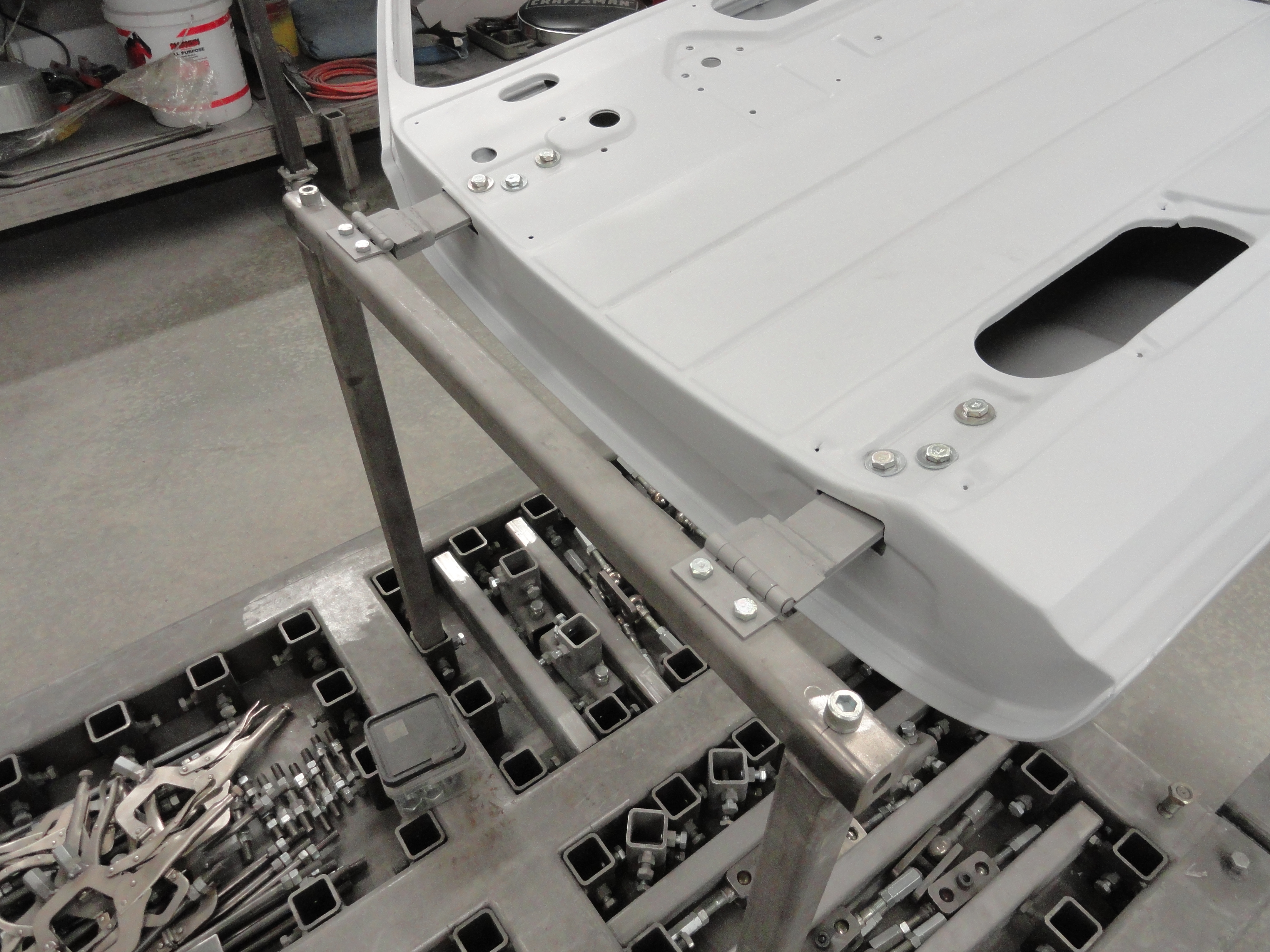
The rest of this setup for doors is just parts that you already made for your SuperJig. I took two 30 inchers and placed T connectors on top and then put them in the appropriate holes on the base to coincide with where the door will rest squarely. On the other side of the jig, I noticed I need to go 'outside the box' and used two very short 1-1/2" square pieces that were just the right size to go inside my 45 degree connectors, then the regular short piece, then the other 45 degree then capped it off with a cap. This turned out right where it sat level on both sides of the hinge. Use some sort of carpet, blanket, or other covering over the stop areas to keep your doors from getting damaged. Once everything is tightened down, that door will be VERY solid.

Once you have made both resting ends, place the door with the bars on it carefully up against the hinges resting one end on the rest, the other in your hand until you can get two vise grip clamps on. Once the vise grips are holding the hinges securely, you can make minor adjustments until you are ready to weld the hinges to the bars as close to center as possible. Weld them as shown. I just tacked them in place, then removed the assembly and did the rest of the welding on the welding table. Clean it up to your satisfaction, bolt everything back together, and do it all over again for the other door! Now you can see the benefits of the SuperJig. We didn't have to reinvent the wheel for most of it, it was done for us already, and now you have attachments for your doors! With your new door system, you can go from sandblasting to final paint and get to everything with ease.
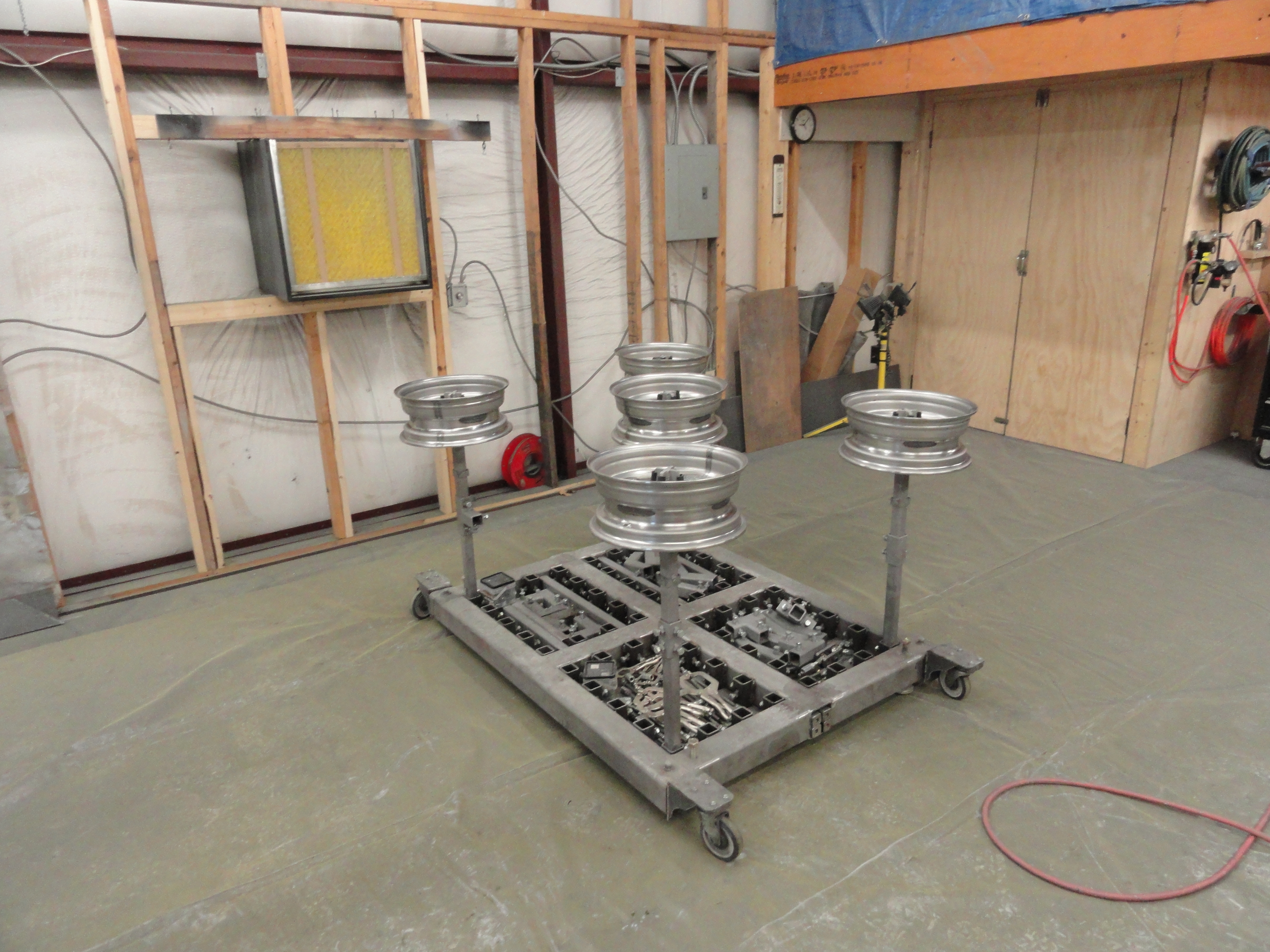
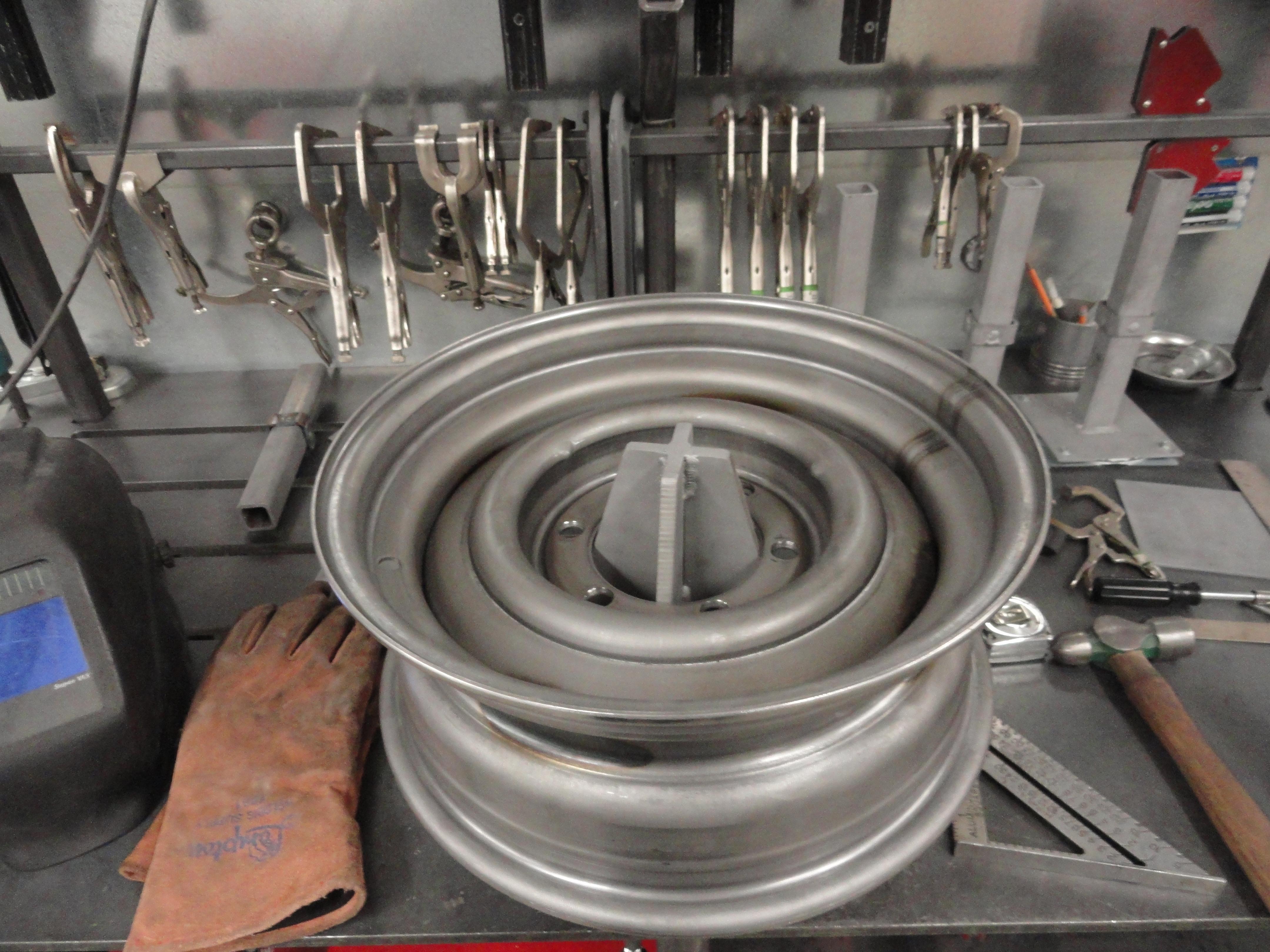
For every project vehicle, you have potentially five wheels to process/paint. This add-on will make it so you can do them all at once! We will use our SuperJig for the base of each spinner and place one in all four corners and one in the middle. This gives us all the access we need to sandblast, primer and paint our wheels all at once. We will coat the inside of each rim first, then flip them over and do the front side. This allows us to get to every square inch of the rim. Not shown in my pictures, is the 3/8" fuel line hose split to cover the angle where the rim meets the spinner. Use RTV to adher the rubber hose to the metal sides. This makes it safe to turn them over and paint the other side without marring the finish.
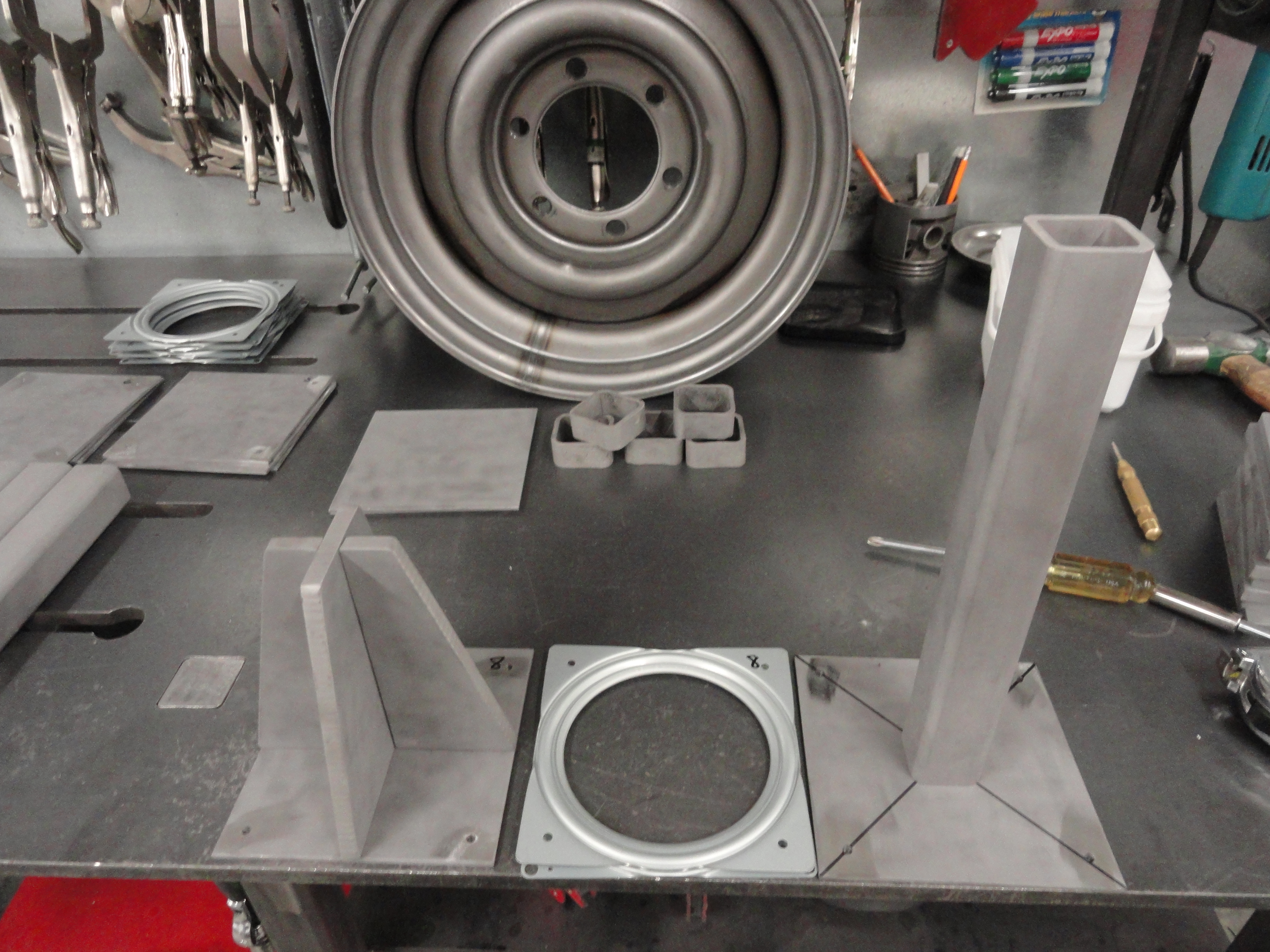
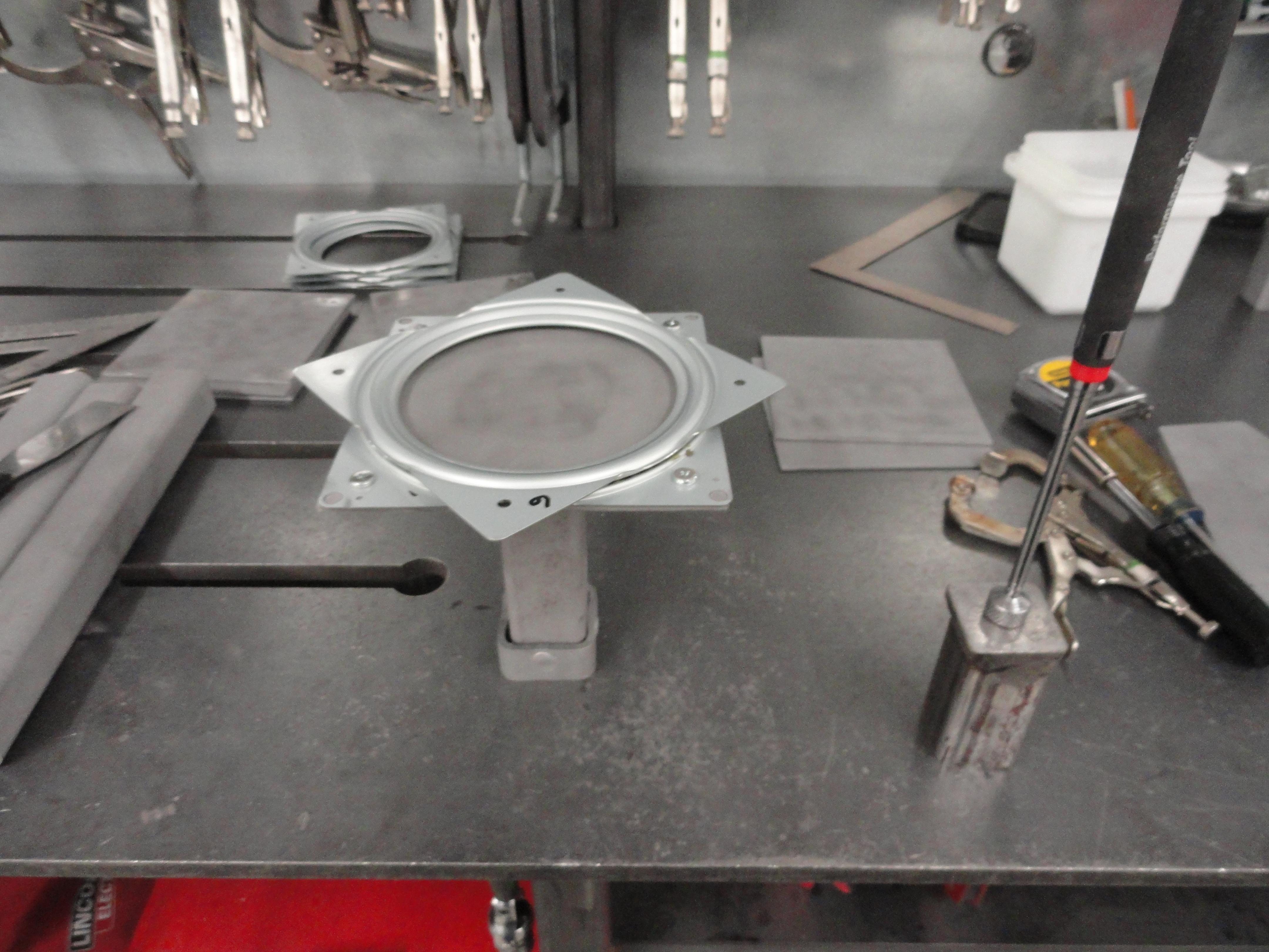
Start by purchasing 5 each of 6 inch square Lazy Susan bearing assemblies. I got them from the local lumber yard. Next cut out 2 each of 6 inch by 6 inch pieces of 11 gauge plate for each spinner. These will be considered Top and Bottom Plate. The Bottom Plate needs a 1-1/2" by 12" square tube with 1/8" walls welded to the center of it. This will be mounted to the SuperJig using the couplers we made previously.
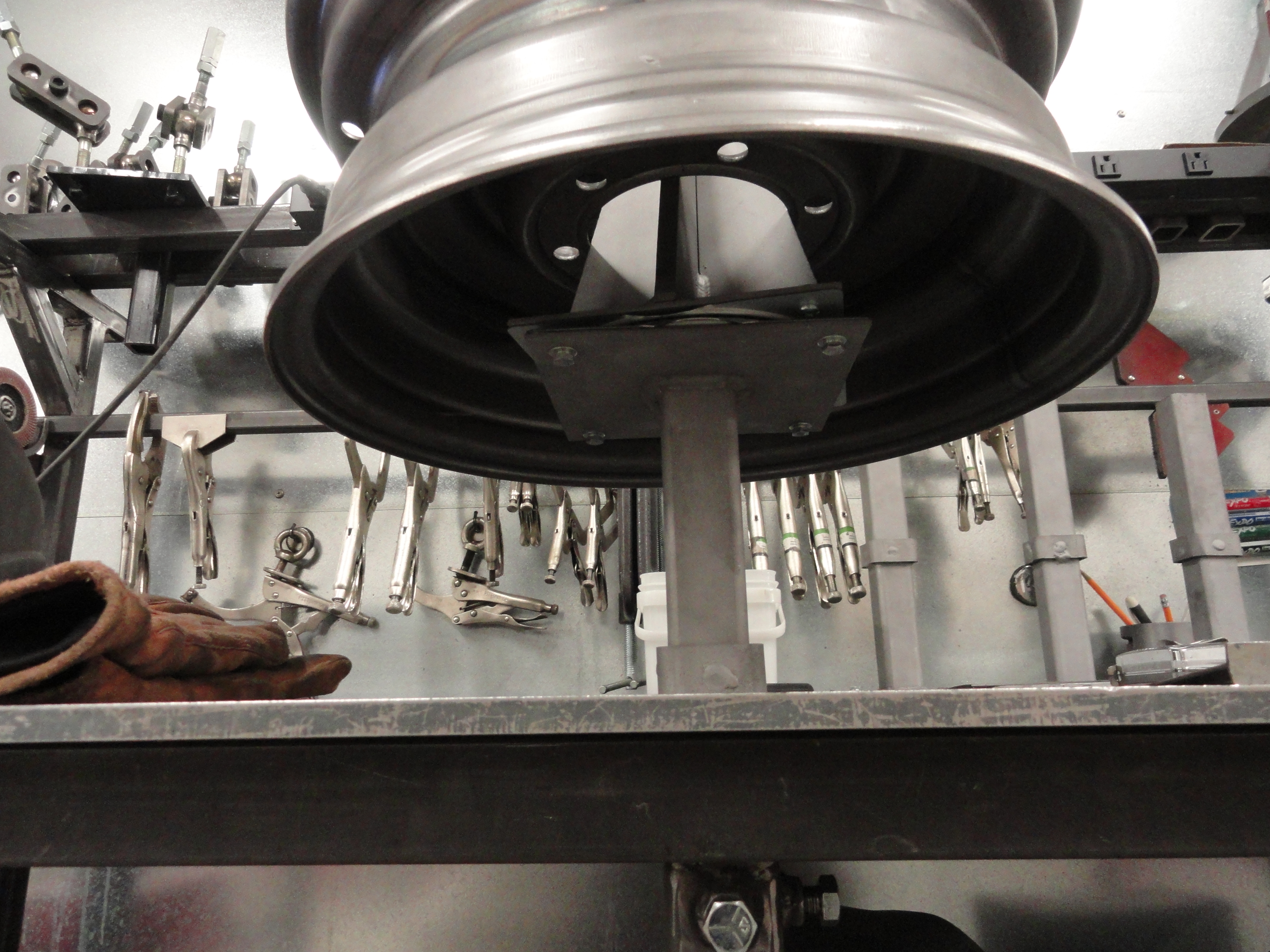
Next drill the four holes in both of these plates to secure the Lazy Susan bearing mechanism. Next, at the 6 inch point of the 12 inch pipe, place a 2 inch by 3/4" square tube STOP so that when you drop the unit into the SuperJig or any of your table receptacles, it stops before bottoming out at 6 inches. Now that you have the base completed, we need to make the part that comes in contact with the wheels.
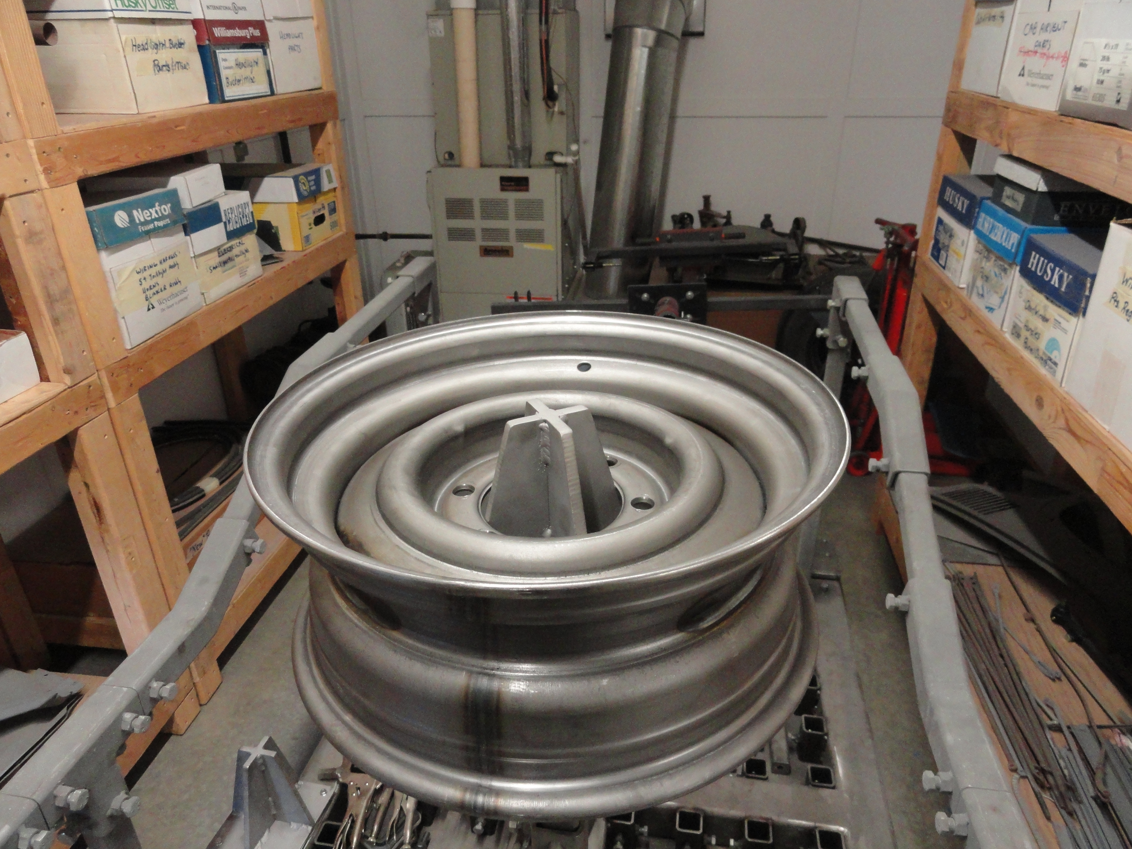
For each Spinner, cut one piece of 3/8" by 6" by 6" plate steel and cut the taper from the bottom to the top on each side at a 14 degree angle. Next cut two pieces of 3/8" by 2-3/4" and angle them at the same 14 degrees. That assembly is then welded to the base as shown. Grease the bearings well, clean off the excess so it does not end up in your paint, and you are good to go!