


Deve's Technical Network
1947-1955 1st Chevy Trucks
216/235/261 Engine Solutions & More

Before we get to the Revelations, let's examine the stock 1947-1955 GM Fuel System. The system consists of a Fuel Storage Tank, a 6 inch Rubber Hose (1/8" NPT Female to 5/16" Flare), 5/16" Fuel Hard Line, a Mechanical Fuel Pump, more 5/16" Hard Line, a Glass Bowl Fuel Filter and a Carburetor. For the electricals we have a Gauge and a Sending Unit. This system works quite nicely for it's time. With the advent of modern technology, there are ways to make it much better, but it is nice we have something solid to work with.
The reason for the rubber hose coming off the in-Cab fuel tank is that the Cab floats on Cab mounts that allow for movement separate from the frame. At the tank there is a fuel shutoff valve. This valve when turned all the way in, keeps fuel from flowing to the fuel pump. One of the improvements I would make is to put a short SOFT line from the frame to the pump. This is because the engine moves independently from the frame also causing excessive pressure on the hard line.
The Pro's are, it is a simple and mostly reliable system. Hats off to the engineers at GM who managed to keep 65 year old technology pretty much in Modernity. The Con's are harder starting after the Carburetor's fuel bowl contents deplete as a result of evaporation, pump longevity due to todays more caustic gas formulas and lack of a filter between the tank and the fuel pump.
What do I mean by more caustic? Every lawn mower and small engine manufacturer in the world has a warning that says, if you use Ethanol, be sure to drain your gas tank after THIRTY DAYS because the gas will become unusable after that. Ethanol is known to corrode some rubber and neoprene products at a substantially higher rate. My suggestion is to avoid Ethanol for your vintage vehicles at all costs. Nothing good can come from a 30 day restriction on fuel usage! For those of you who do not have a "NO ALCOHOL" gas pump available, get a product called "STABIL" and use it with every fill-up.
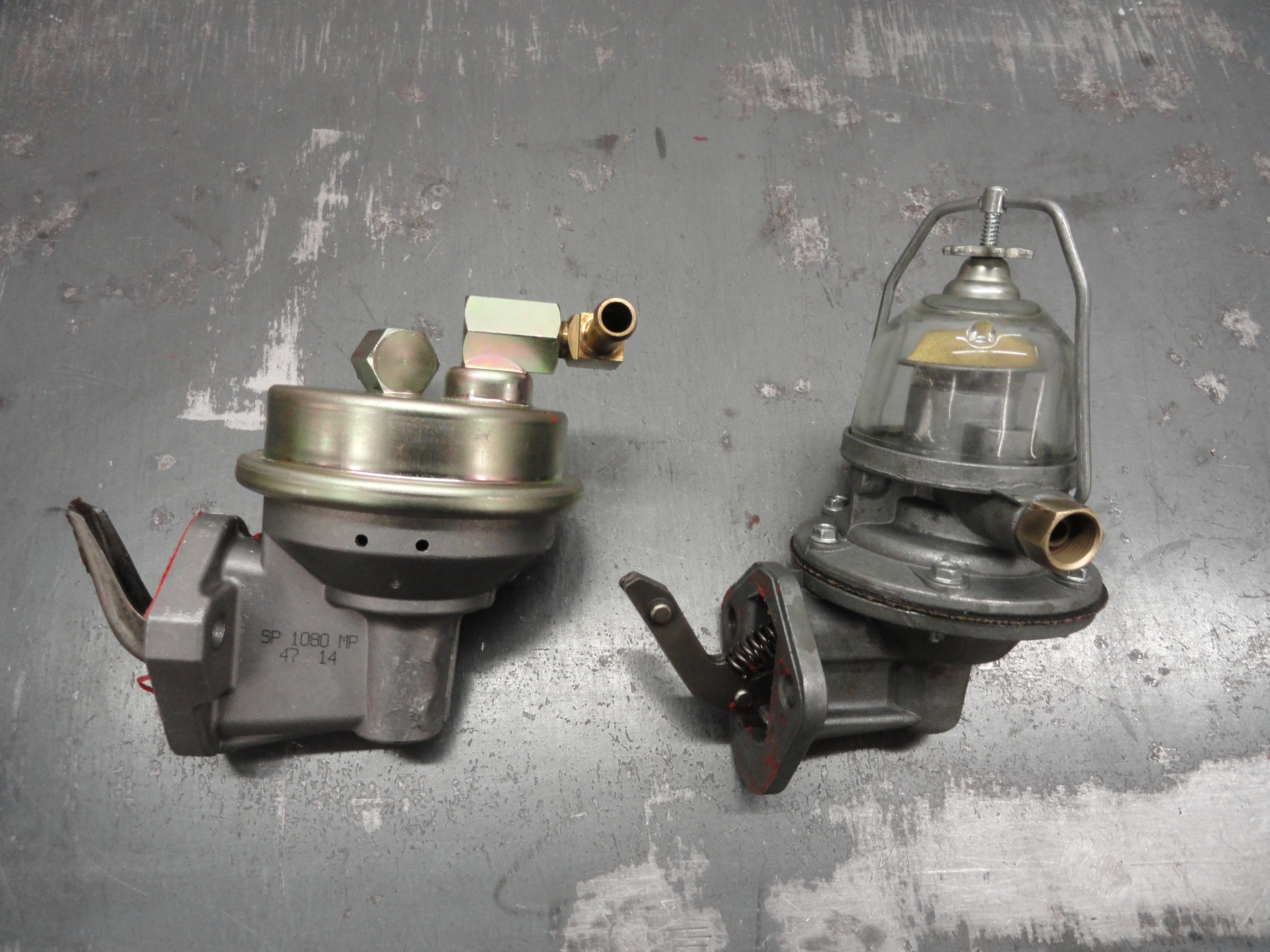
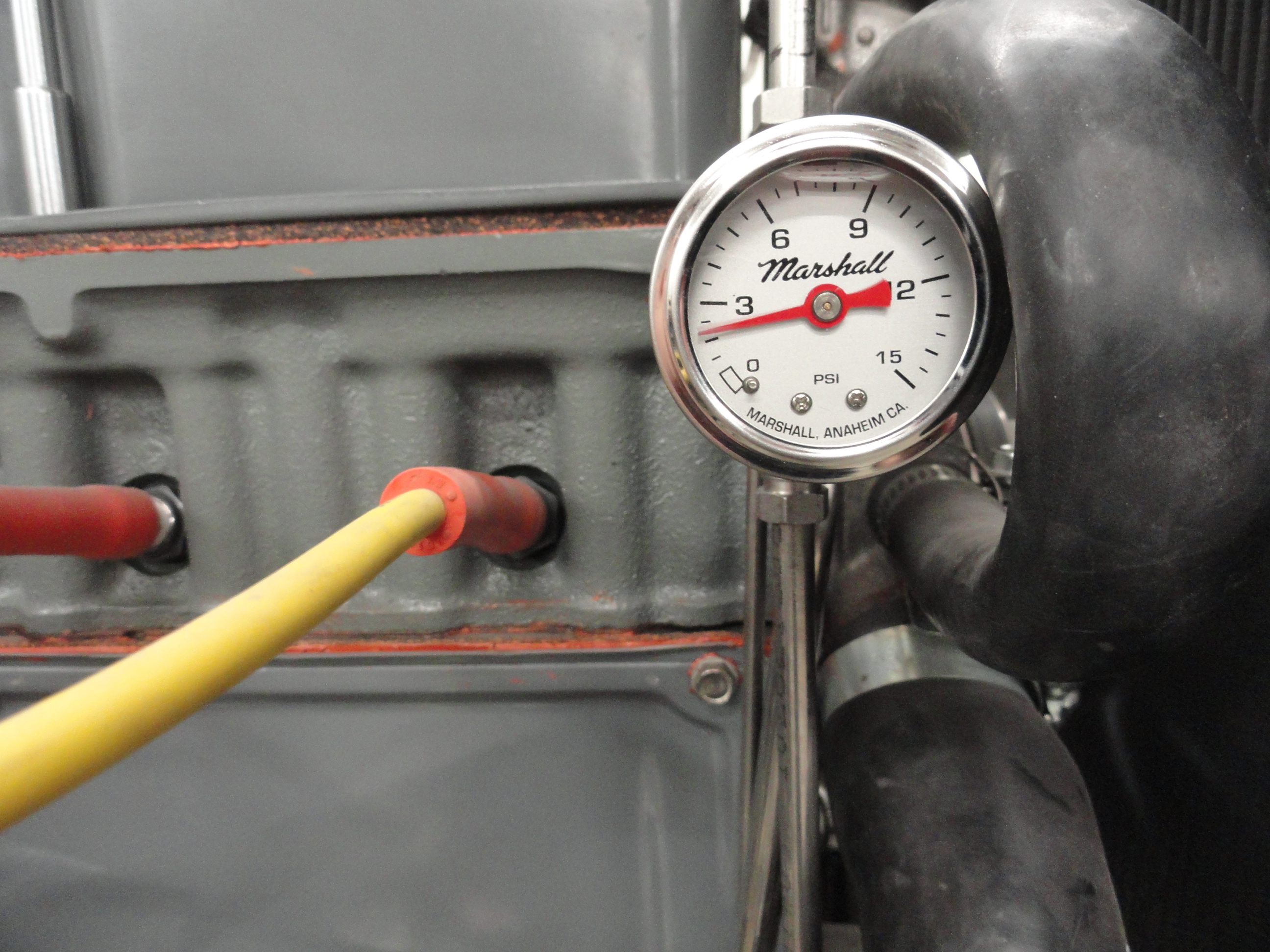
The stock mechanical fuel pump works off the engines Camshaft. Due to the cam action, the pump's lever being in contact with the cam allows for fuel flow in the direction of the Carburetor. The stock mechanical Fuel Pump is rated to deliver a maximum of 25 gallons per hour and provide between 3.5 and 4.5 pounds per square inch (PSI) of pressure against the Carburetors Float Valve. This means that no more than 25 gallons each hour will be consumed by an engine with that fuel delivery system. It also means the pump is not responsible for pushing more fuel into the Carburetor than can be consumed due to the Carb's Float Valve only allowing enough fuel in to keep the Carburetor's Fuel Bowl Full.
When I say "fuel flows in the direction of the Carburetor", I mean ONLY in the direction of the Carb. Fuel is restricted from flowing backwards by the mechanical Fuel Pumps check valve. There is no check valve the other direction, which is significant because it means fuel can freely flow past the mechanical pump if another pump is used to augment the existing one. This enables us to do some pretty cool stuff to make this system far better!
The Mechanical Fuel Pump has gone the way of the Dinosaur as they say and Mechanical Fuel Pumps have not been used for OEM purposes since the mid 1980's. They do however have one advantage; They stop fuel flow when the engine stops. In order for us to consider an Electric Fuel Pump, we need a way to stop fuel flow when the engine stops. It is not safe or desirable to just hook an electric pump to 12 volts and let it run all the time. In the case of an accident, you do not want fuel pumping out of the tank, so we must devise a way to ensure the fuel pump stops dead upon engine shutdown.
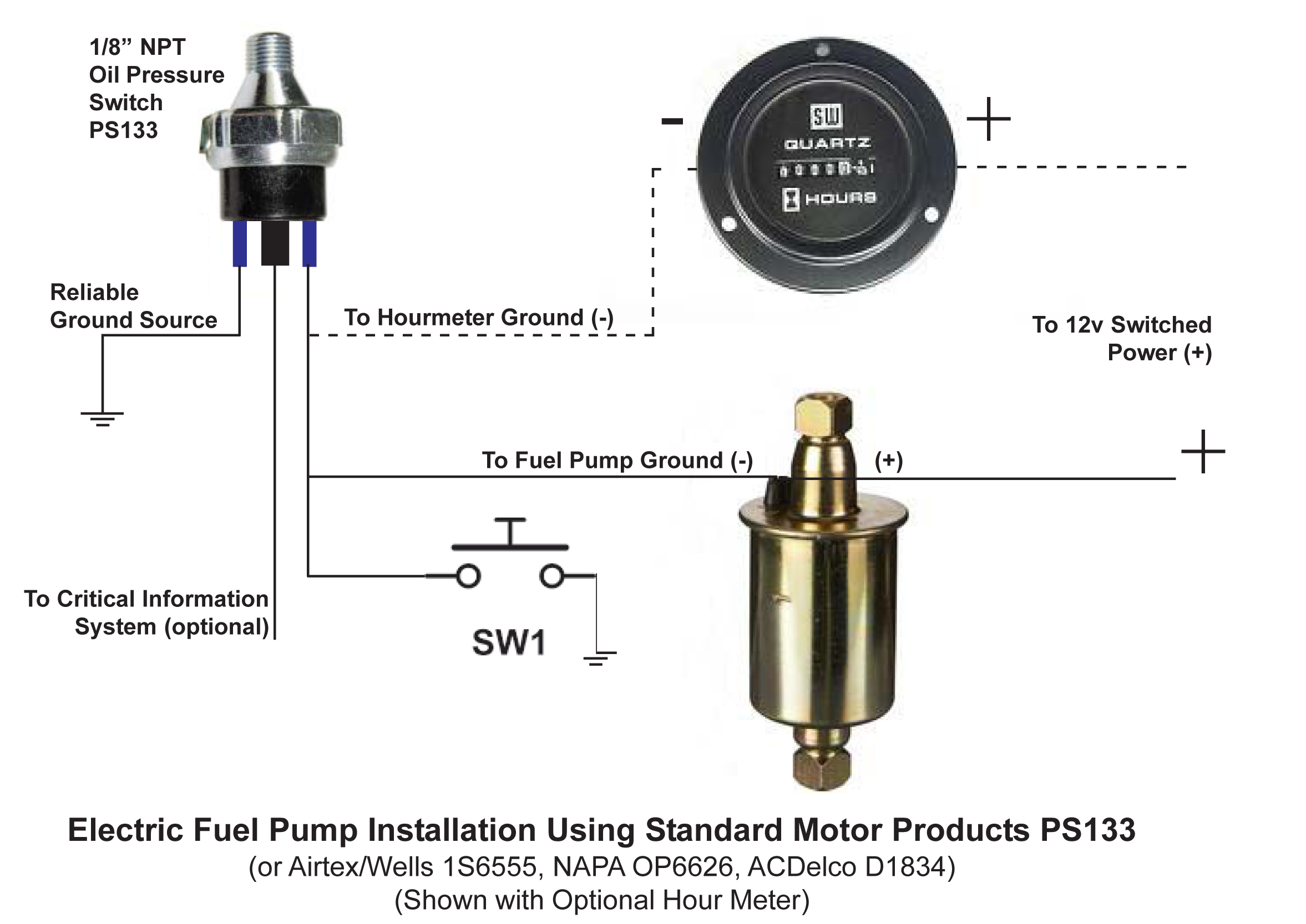
The way the GM got around this in the 80's and 90's on OEM installations was using a Fuel Safety Switch that was based on the presence of Engine Oil Pressure. The Standard Motor Products PS133 is a good example of an oil pressure switch used for this purpose. The two terminals across from each other are connected together internally only after 12psi of oil pressure is present. Properly wiring this switch into the system will prevent the Electric Fuel Pump from coming on until the oil pressure is at or above 12 psi. This puts the mechanical and electrical pumps on Par with each other allowing them to behave the very same in the Fuel System.
Electric Fuel Pumps work similar to their mechanical counterpart in that they PULSE fuel through the system. The diaphragm that pushes the fuel is smaller and the pump is OEM so it has been engineered for modern fuels. Electric Pumps work exactly the same in the vehicle's fuel system as the mechanical ones; when sufficient fuel is pumped into the Carburetor to bring the Carbs Float to maximum, the fuel pump stops pumping. This is because the Carb's float valve will hold back about 10psi of pressure and the pump is only rated to put out 3-5psi. Really, the only difference between mechanical and electrical pumps is the method by which they are powered.
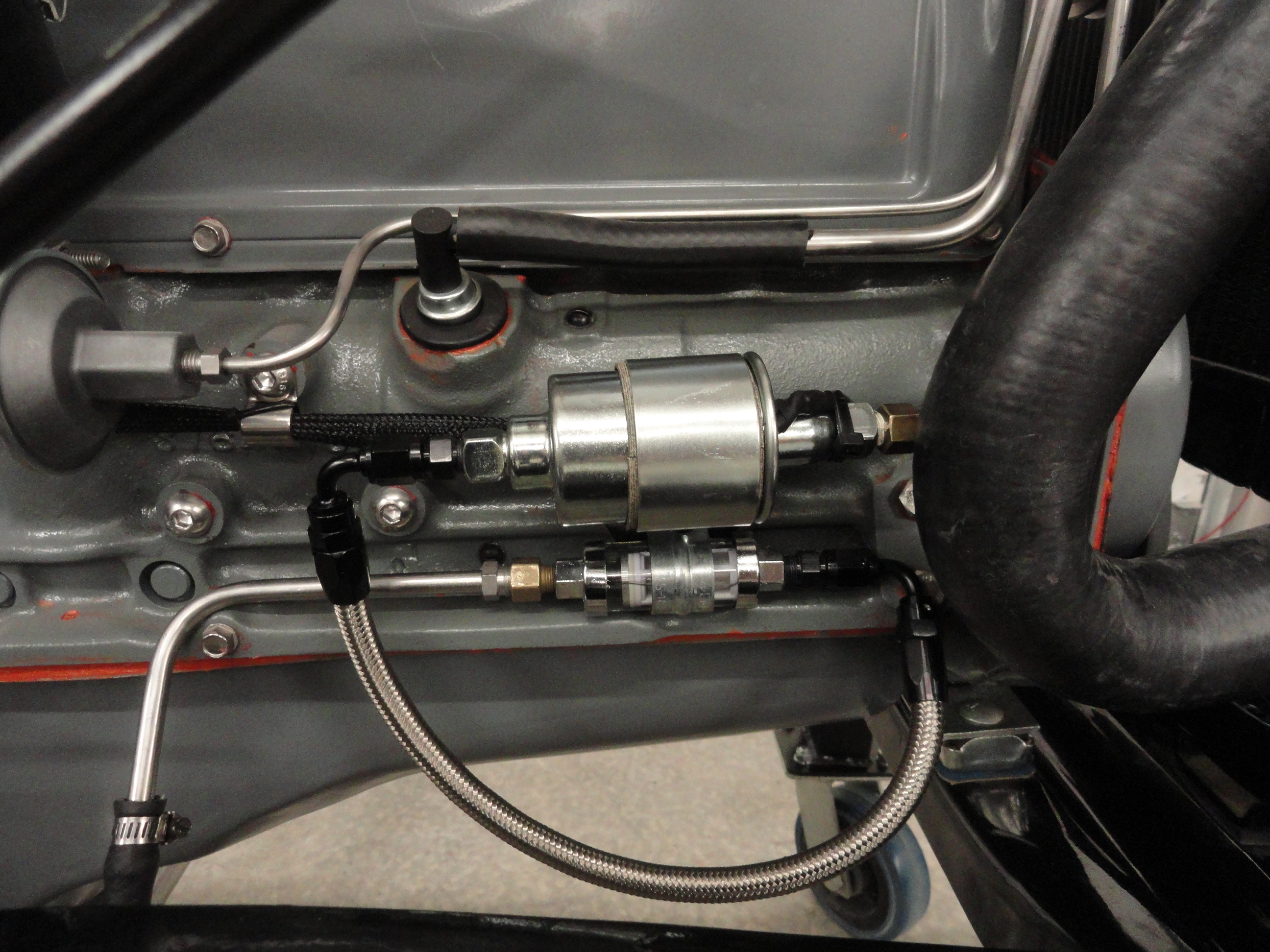
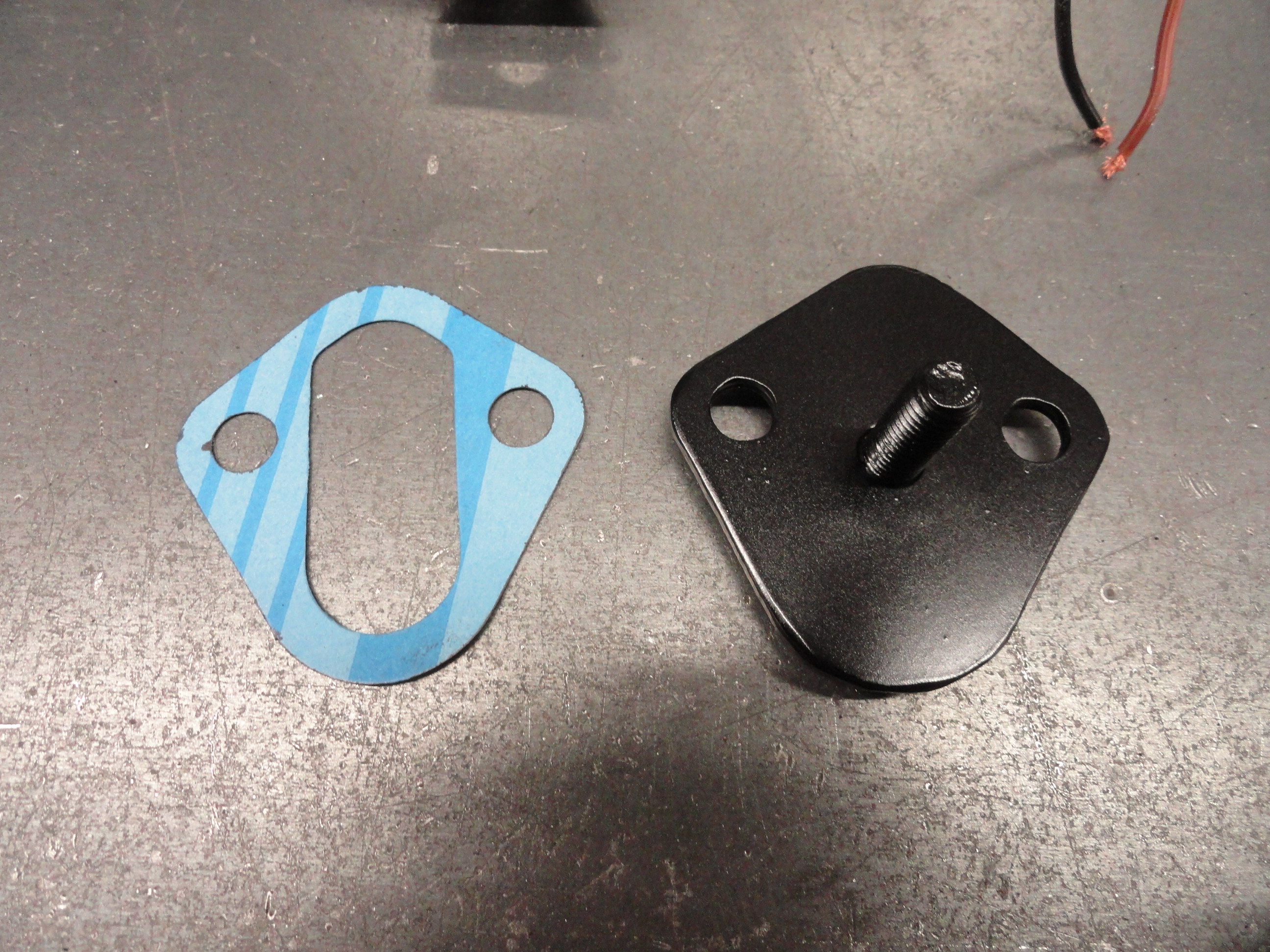
Installation of an Electric Fuel Pump can be accomplished by mounting to the frame rail, or if you are replacing your existing Mechanical Pump you can make a bracket that places the new pump exactly where the old one was located at the side of the engine. The advantage to mounting it in the same place is, with a little tweaking, we can use our same hard lines to connect it. This bracket can easily be made out of 5/16" steel. Trace around a fuel pump gasket for the pattern, drill the two holes for mounting, then drill a 3rd hole in the center for a 3/8" bolt, weld the bolt into place from the inside, and you are good to go. I feel welding is the safest way to do this since you do not want a condition where that bolt could drop into the engine. Be sure to check our Farm-It-Out page. Most of the ideas here are available for purchase.
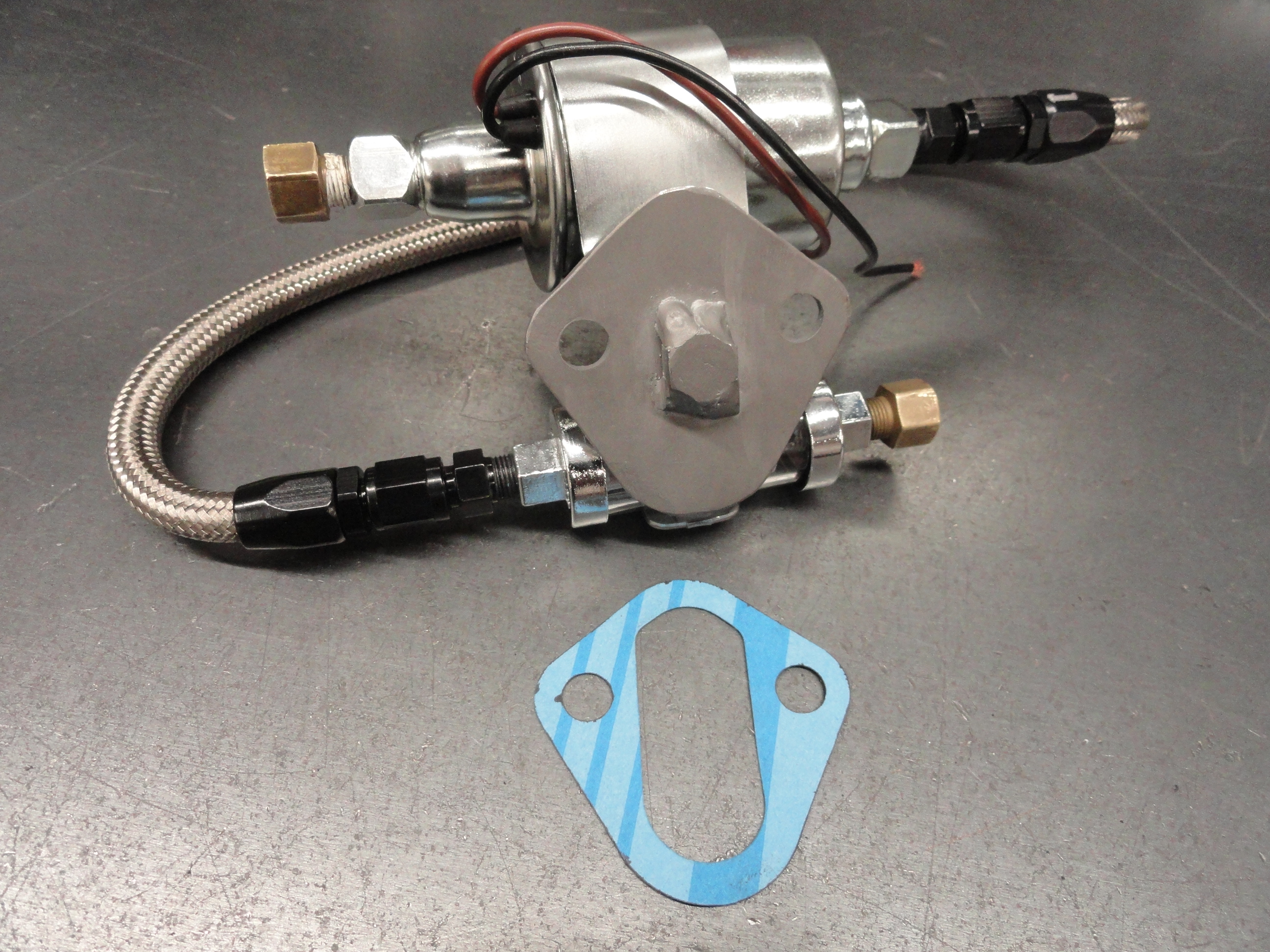
The idea of using the same mounting surface and bolt holes for the electric pump from where the mechanical pump used to be worked great. There may be some minor tweaking of the hard line to get it to fit, but may save having to recreate hard lines. This is more true with the 1940-1953 pumps (mechanical) that have the inlet and outlet directly across from each other. If you have one that has offset in's and out's, you may need new hard lines to the carb at least. One Important Caveat; The electric pump works great in the same location as the mechanical pump IF you went to the PCV system. The road draft tube gets in the way and cannot be used if mounting the electric pump there. If you are not running PCV, you should be! The article covering that is HERE.
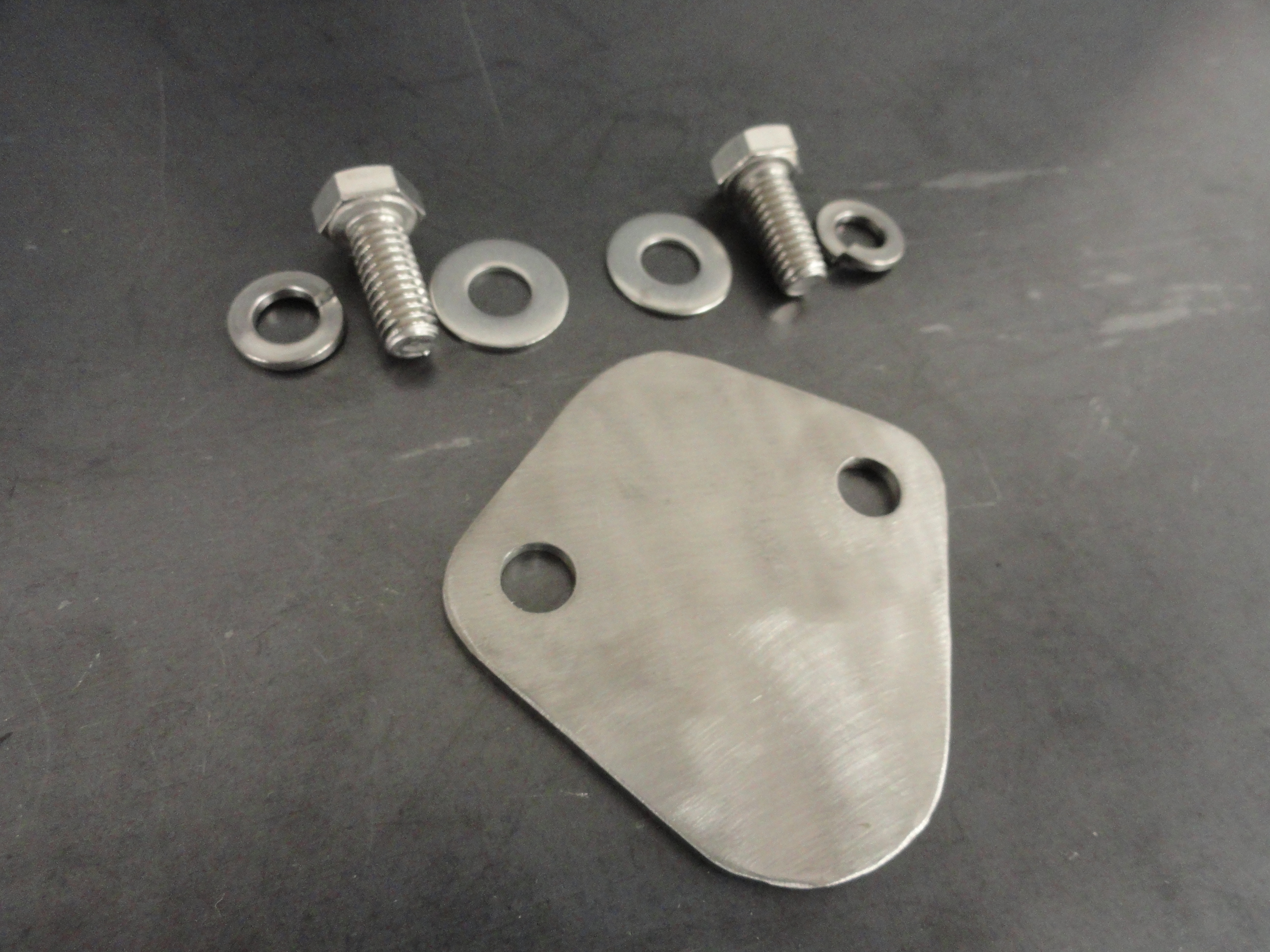
Let's not forget we need to address the hole in the engine block that used to accommodate the mechanical fuel pump. This of course if you choose to remove the mechanical one. Take a mechanical fuel pump gasket and trace around it on a nice piece of 14 gauge Stainless Steel! Drill the appropriate 5/16" holes, add a few stainless bolts and hardware and some gasket sealer, and you have really done things in style!
Finding just the right Electric Fuel Pump took a little research but we found some very good candidates. Here is the current list:
To build everything outlined in this article yourself, some part numbers might come in handy. Here is the list of everything needed. Hardware is stainless steel where-ever possible.
All of the Electric Pumps and Filter use a 1/8 NPT (1/8"-27) thread size and allow you to use either Barbs and Flex rubber hose, or make it more permanent with hard lines using flare fittings. The common Fuel Line size is 5/16" Tube. A few other interesting facts is the electric pump should be attached to your Ignition Switch and uses about 3-5 amps of current. A 10 amp fuse will work great using 14 gauge hookup wire. Follow the schematic and enjoy a very reliable fuel system. Of course nothing is foolproof, but ask yourself why ALL car manufacturers went to Electric years ago. The Electric solution is considered more reliable and another thing to not have to concern yourself with when you start your engine! I am not sure if engine performance is increased in removing the mechanical pump or not.
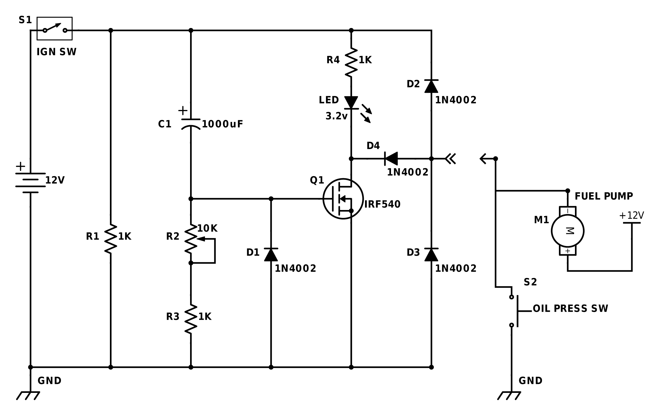
So far we have been able to perfectly emulate the Mechanical Fuel Pump using an Electric one. We have it mounted and delivering the exact same fuel volume. We have one MAJOR improvement to make however. With the electric pump wired to the Fuel Safety Switch (oil pressure), we STILL do not get fuel to fill the Carburetor's depleted fuel bowl until after cranking. The easy way to solve it is to just add a momentary push button inside the vehicle. But why should you have to push a button when we are in the year 2016? Why not incorporate a very reliable circuit that starts the fuel pump upon hitting the IGN Ignition Switch, runs the Electric pump for XX Seconds then shuts down deferring control to the Fuel Safety Switch? The system is cycled and ready for re-deployment by turning the IGN switch off.
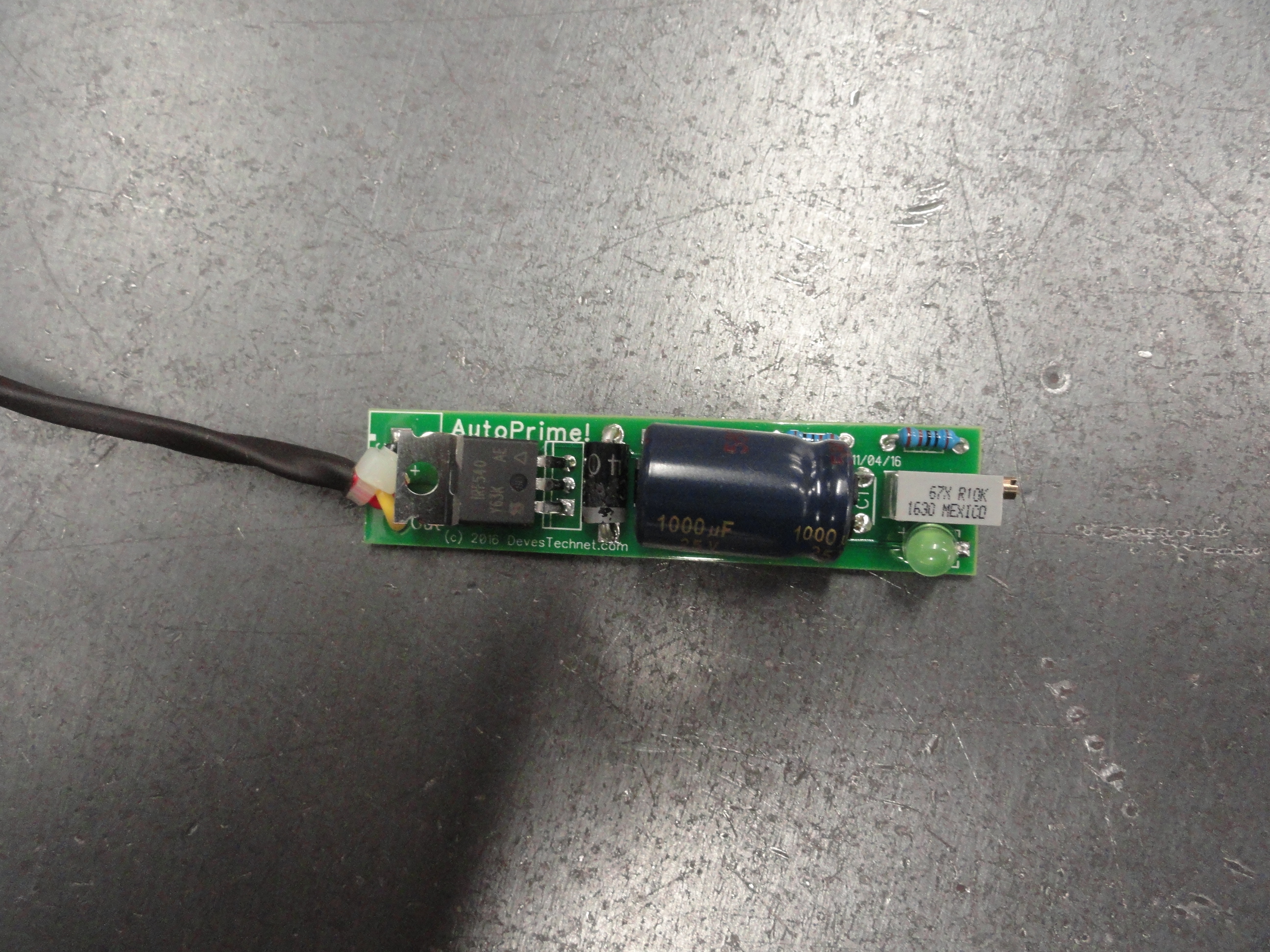
Enter AutoPrime! This little circuit uses no moving parts such as relays to get the job done. We instead chose a power transistor (MOSFET) for triggering. With no parts to wear out and a very intuitive, long lasting design, we can be sure our little circuit will be long lasting and care free. We need our circuit protected against the elements and an easy install, so I chose to encase this rascal in 3/4" (ID) PVC Pipe. The LED is viewed through the end cap and the variable resistor to allow you to adjust the number of seconds (between 2 and 15) is on the end cap as well.

As with everything else on Deve's Technical Network, the plans to do this yourself are here in this document. You are
not forced to pay anyone else to do it, however, I ask that if you make one, make ONE for yourself and refer your friends
to our Farm-It-Out section. I have plenty in stock
and cannot use all of them myself! Use the schematic and make it yourself if you wish. I use Digi-Key.com for all of the
parts listed below except for the circuit board. For you to do it yourself you would need to do it on a generic proto
board or order the bare board from us. For safety sake, get the professionally made one from us!
So far we have replaced the mechanical pump with a more modern electrical pump, placed it in the location of your choice, and made it work as advertised. But what if we already have a perfectly good mechanical pump and wish to provide a Redundant Backup System? The word redundant gets a bad name but in the Aircraft industry, it is a mainstay concept. Two of everything means a higher degree of safety. In this case it means twice the reliability of your fuel system. Electric one dies, fuel still gets there. Mechanical one dies, fuel still gets there.
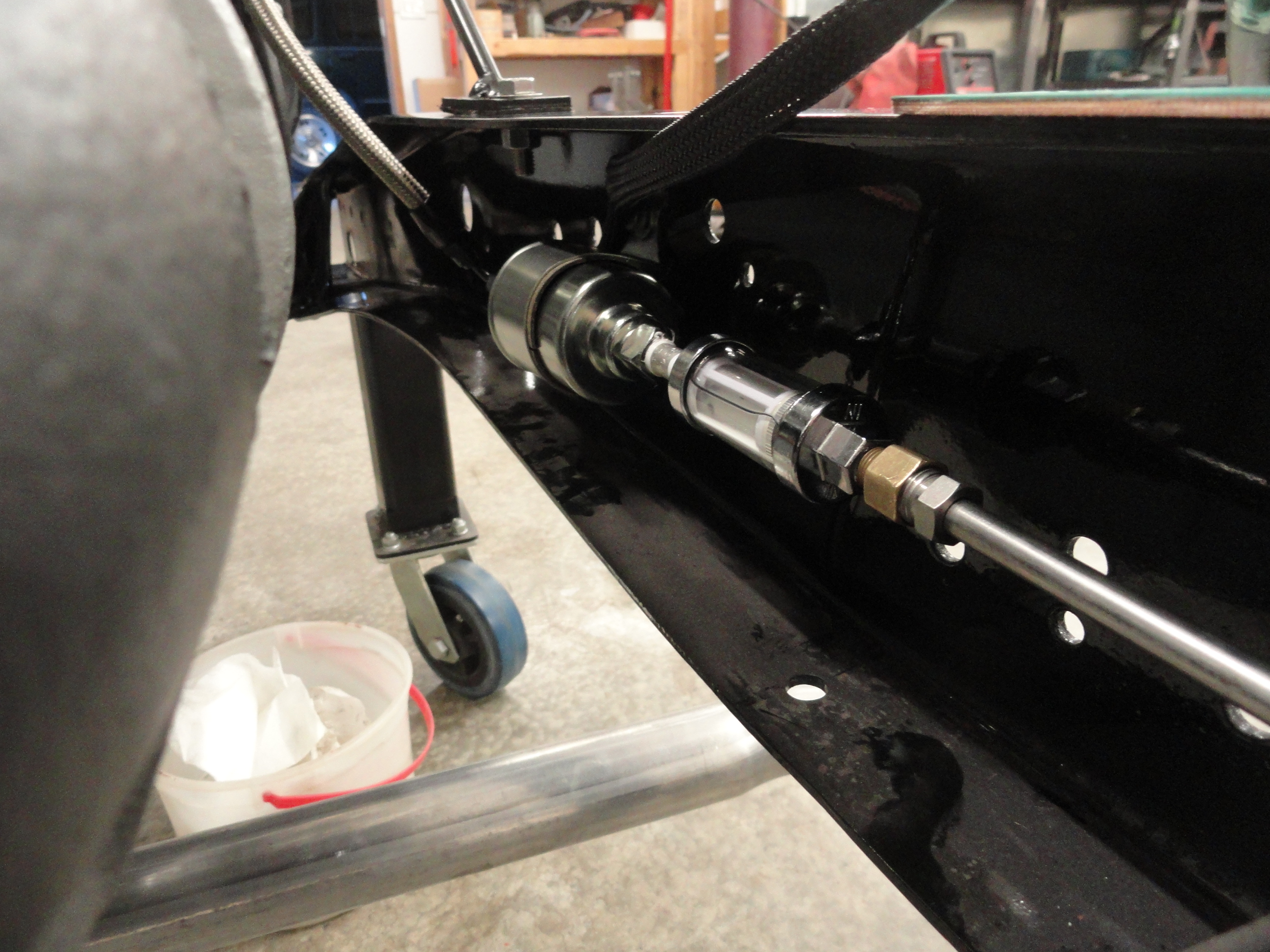
Turns out that in our testing, we discovered that fuel flows from the tank to the carburetor without any restriction even if the electrical pump is not connected, or the mechanical one is not working. This makes it possible to just put the electrical pump before the mechanical one on the frame rail and everything will work together perfectly. The pressure is NOT additive, so everything maintains its 3.5 - 4.5psi window.
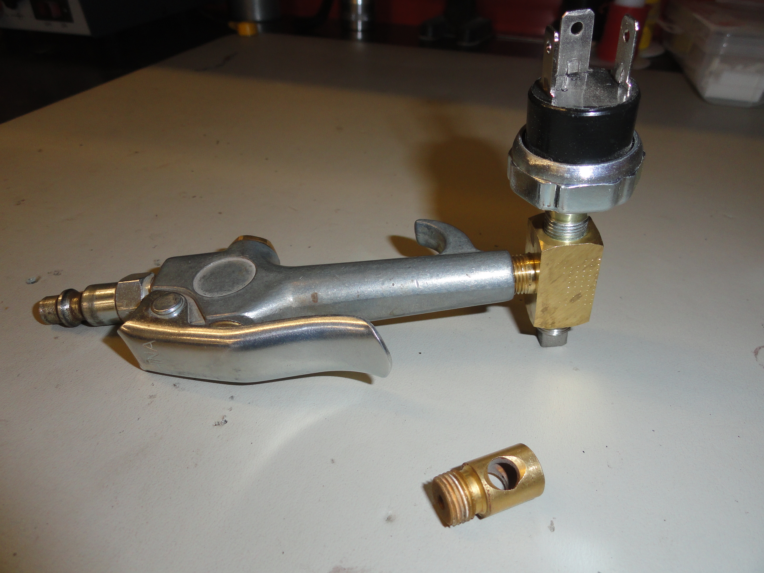
Simply install the electric pump on the framerail and connect a soft line to the mechanical pumps inlet. To test the safety switch, you can use a standard air blower gun. Remove the safety end and screw the switch in then using compressed air, you can test the switch.
We didn't cover the Fuel Gauge or the Sender because that is fully covered in: Going Native! near the bottom of the page.
We also didn't cover the Carburetor because that is also fully covered in: Servicing the Rochester B Carb
With a super fast starting Fuel System, it may be interesting to look at: HEI Using Your Stock Distributor to enhance the other side of things.