

The Strength and type of steel used in a bolt is supposed to be indicated by a raised mark on the head of the bolt. The type of mark depends on the standard to which the bolt was manufactured. Most often, bolts used in machinery are made to SAE standard J429, and bolts used in structures are made according to various ASTM standards. The tables below give the head markings and some of the most commonly-needed information concerning the bolts. For further information, see the appropriate standard.
| SAE Bolt Designations | ||||
| SAE Grade No. | Size Range | Tensile Strength (ksi) | Material | Head Marking |
| 1 | 1/4 through 1 1/2 | 60 | Low or medium carbon steel |  |
| 2 | 1/4 through 3/4 7/8 through 1 1/2 |
74 60 |
||
| 5 | 1/4 through 1 1 1/8 through 1 1/2 |
120 105 |
Medium carbon steel, quenched and tempered |  |
| 5.2 | 1/4 through 1 | 120 | Low carbon marten-site steel, quenched & tempered |  |
| 7 | 1/4 through 1 1/2 | 133 | Medium carbon alloy steel, quenched & tempered |  |
| 8 | 1/4 through 1 1/2 | 150 | Medium carbon alloy steel, quenched & tempered |  |
| 8.2 | 1/4 through 1 | 150 | Low carbon marten-site steel, quenched & tempered |  |
| ASTM Bolt Designations | ||||
| ASTM Standard | Size Range | Tensile Strength (ksi) | Material | Head Marking |
| A307 | 1/4 through 4 | 60 | Low carbon steel |  |
| A325 Type 1 |
1/2 through 1 1 1/8 through 1 1/2 |
120 105 |
Medium carbon steel, quenched and tempered |  |
| A325 Type 2 |
1/2 through 1 1 1/8 through 1 1/2 |
120 105 |
Low carbon marten-site steel, quenched & tempered |  |
| A325 Type 3 |
1/2 through 1 1 1/8 through 1 1/2 |
120 105 |
Weathering steel, quenched & tempered |  |
| A449 | 1/4 through 1 1 1/8 through 1 1/2 1 3/4 through 3 |
120 105 90 |
Medium carbon steel, quenched and tempered |  |
| A490 Type 1 |
1/4 through 1 1/2 | 150 | Alloy steel, quenched and tempered |  |
| A490 Type 3 |
1/4 through 1 1/2 | 150 | Weathering steel, quenched and tempered |  |
Often one will find "extra" marks on a bolt head - marks in addition to those shown above. Usually, these marks indicate the bolt's manufacturer.
ASTM A325 Type 2 bolts have been discontinued, but are included above because they can be found in existing structures. Their properties can be important in failure investigations.
While the bolts shown are among the most common in the U.S., the list is far from exhaustive. In addition to the other bolts covered by the SAE and ASTM standards, there are a host of international standards, of which ISO is perhaps the most well-known.
The strength of a bolt is determined by its diameter and the strength of the material from which it is made. Minimum material strengths for various grades of bolts are given in a related page. Here, we deal with the diameter.
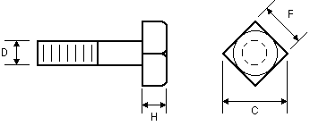
It may seem that the determination of a bolt's diameter is a simple matter of measurement, and this is indeed the case when the shank is exposed. In many cases, however, the shank is hidden, and the engineer who is charged with determining the strength of the bolted joint must infer the bolt's diameter from the size of its head. Fortunately, there are standards that govern the relationship between bolt size and head size. The following tables are based on information in the following:

| Square Bolt Dimensions (inches) | |||
| D | F | C | H |
| 1/4 | 3/8 | 1/2 | 3/16 |
| 3/8 | 9/16 | 13/16 | 1/4 |
| 1/2 | 3/4 | 1 1/16 | 5/16 |
| 5/8 | 15/16 | 1 5/16 | 7/16 |
| 3/4 | 1 1/8 | 1 9/16 | 1/2 |
| 7/8 | 1 5/16 | 1 7/8 | 5/8 |
| 1 | 1 1/2 | 2 1/8 | 11/16 |
| 1 1/8 | 1 11/16 | 2 3/8 | 3/4 |
| 1 1/4 | 1 7/8 | 2 5/8 | 7/8 |
| 1 3/8 | 2 1/16 | 2 15/16 | 15/16 |
| 1 1/2 | 2 1/4 | 3 3/16 | 1 |

| Hex Bolt Dimensions (inches) | |||
| D | F | C | H |
| 1/4 | 7/16 | 1/2 | 3/16 |
| 3/8 | 9/16 | 5/8 | 1/4 |
| 1/2 | 3/4 | 7/8 | 3/8 |
| 5/8 | 15/16 | 1 1/16 | 7/16 |
| 3/4 | 1 1/8 | 1 5/16 | 1/2 |
| 7/8 | 1 5/16 | 1 1/2 | 9/16 |
| 1 | 1 1/2 | 1 3/4 | 11/16 |
| 1 1/8 | 1 11/16 | 1 15/16 | 3/4 |
| 1 1/4 | 1 7/8 | 2 3/16 | 7/8 |
| 1 3/8 | 2 1/16 | 2 3/8 | 15/16 |
| 1 1/2 | 2 1/4 | 2 5/8 | 1 |
| 1 3/4 | 2 5/8 | 3 | 1 3/16 |
| 2 | 3 | 3 7/16 | 1 3/8 |
| 2 1/4 | 3 3/8 | 3 7/8 | 1 1/2 |
| 2 1/2 | 3 3/4 | 4 5/16 | 1 11/16 |
| 2 3/4 | 4 1/8 | 4 3/4 | 1 13/16 |
| 3 | 4 1/2 | 5 3/16 | 2 |
| 3 1/4 | 4 7/8 | 5 5/8 | 2 3/16 |
| 3 1/2 | 4 7/8 | 5 5/8 | 2 3/16 |
| 3 3/4 | 5 5/8 | 5 1/2 | 2 1/2 |
| 4 | 6 | 6 15/16 | 2 11/16 |

| Heavy Hex Bolt Dimensions (inches) | |||
| D | F | C | H |
| 1/2 | 7/8 | 1 | 3/8 |
| 5/8 | 1 1/16 | 1 1/4 | 7/16 |
| 3/4 | 1 1/4 | 1 7/16 | 1/2 |
| 7/8 | 1 7/16 | 1 11/16 | 9/16 |
| 1 | 1 5/8 | 1 7/8 | 11/16 |
| 1 1/8 | 1 13/16 | 2 1/16 | 3/4 |
| 1 1/4 | 2 | 2 5/16 | 7/8 |
| 1 3/8 | 2 3/16 | 2 1/2 | 15/16 |
| 1 1/2 | 2 3/8 | 2 3/4 | 1 |
| 1 3/4 | 2 3/4 | 3 3/16 | 1 3/16 |
| 2 | 3 1/8 | 3 5/8 | 1 3/8 |
| 2 1/4 | 3 1/2 | 4 1/16 | 1 1/2 |
| 2 1/2 | 3 7/8 | 4 1/2 | 1 11/16 |
| 2 3/4 | 4 1/4 | 4 15/16 | 1 13/16 |
| 3 | 4 5/8 | 5 5/16 | 2 |

| High Strength Structural Bolt Dimensions (inches) | ||
| D | F | H |
| 1/2 | 7/8 | 5/16 |
| 5/8 | 1 1/16 | 25/64 |
| 3/4 | 1 1/4 | 15/32 |
| 7/8 | 1 7/16 | 35/64 |
| 1 | 1 5/8 | 39/64 |
The usual purpose of a bolted joint is to clamp two or more parts together. The clamping force is achieved by applying torque to the bolt head and the nut. The mechanical advantage of the wrench and threads allows one to actually stretch the section of the bolt between the head and the nut (an area known as the grip), creating tension in the bolt. This tension is known as pretension because it exists before any other forces are applied to the joint.
The pretension is transmitted to the mating parts through the head, nut, and any washers that may be present. It squeezes the mating parts together, and, if the joint is designed, assembled, and maintained properly, prevents the mating parts from separating or sliding under normal loads.
The pretension in a bolt is often quite high: 70% of the bolt's tensile strength is not uncommon. At first glance it may seem that this leaves very little strength left to carry the externally applied loads, but it turns out that bolted joints are pretty clever when it comes to carrying loads, and their capacity is greater than you might expect.
Consider the joint shown below: Two D-shaped yokes clamped together with a single bolt. First the bolt is tightened. This draws the faying surfaces (the portions of the mating parts that come in contact) together and applies a compressive force to the mating parts. The joint is in equilibrium, with the compressive force across the faying surfaces equal in magnitude to the pretension in the bolt.

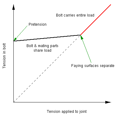
As the external tensile load is applied to the joint, the joint responds by distributing the load. As expected, part of the load goes into the bolt, increasing its tension. But part of the load also goes into the mating parts, decreasing the compression at the faying surfaces. In most joints, this decrease in compression absorbs most of the applied load, shielding the bolt from large increases in tension. Exactly how much is shielded depends on the geometry and material makeup of the joint, but it is not unusual for as much as 90% of the applied load to be taken by the faying surfaces, leaving only 10% to be borne by the bolt.
Of course, the compression at the faying surfaces can only decrease so far. Once the compression has been reduced to zero, the faying surfaces lose contact with each other and the bolt then carries all the applied load. A graph of the bolt tension vs. the applied load shows this change in behavior as a kink at the point at which the faying surfaces part (sometimes referred to as the decompression point.)

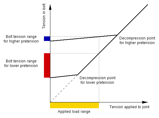
Parting of the faying surfaces is generally considered a bad thing, especially in joints that are subjected to fluctuating loads. If the applied load cycles back and forth between levels below the decompression point, the cyclic stress range in the bolt is relatively low. If, however, the applied load cycles to levels beyond the decompression point, the cyclic stress range in the bolt jumps dramatically and can lead to an early fatigue failure. The graph below shows how a lowered pretension can create this effect.

For this reason, fatigue failures in bolts are often associated with low pretension.