

Deve's Technical Network
1947-1955 1st Chevy Trucks
216/235/261 Engine Solutions & More
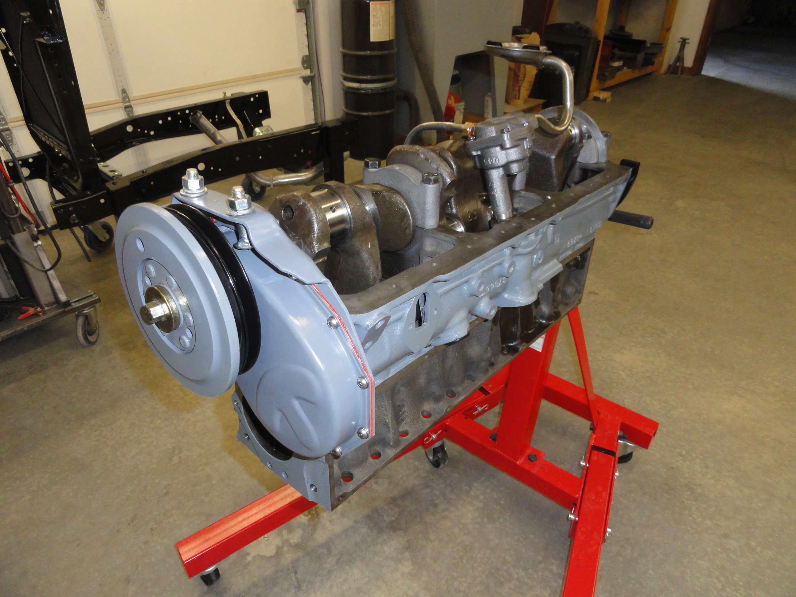
We are going to take a 235 6 Cylinder stock GM engine that we have no idea the condition of it to start, completely tear it down, and by the end of this journey, we are going to test run it, explaining in detail everything we did from start to finish! All sub-systems will be addressed so that the home garage enthusiast can accomplish a start to finish engine rebuild. The idea is to give you instructions on how to make the Engine Shop portion of this journey as inexpensive as possible without compromising quality. We hope you enjoy this very long, very detailed journey.
This engine was sitting in a garage all taken apart in boxes. No idea where each specific lifter was located when it was running, no idea about the condition of the motor, really this engine is completely unknown. This is good for the purpose of documenting because we aren't taking anything for granted. This will make for a really special build!
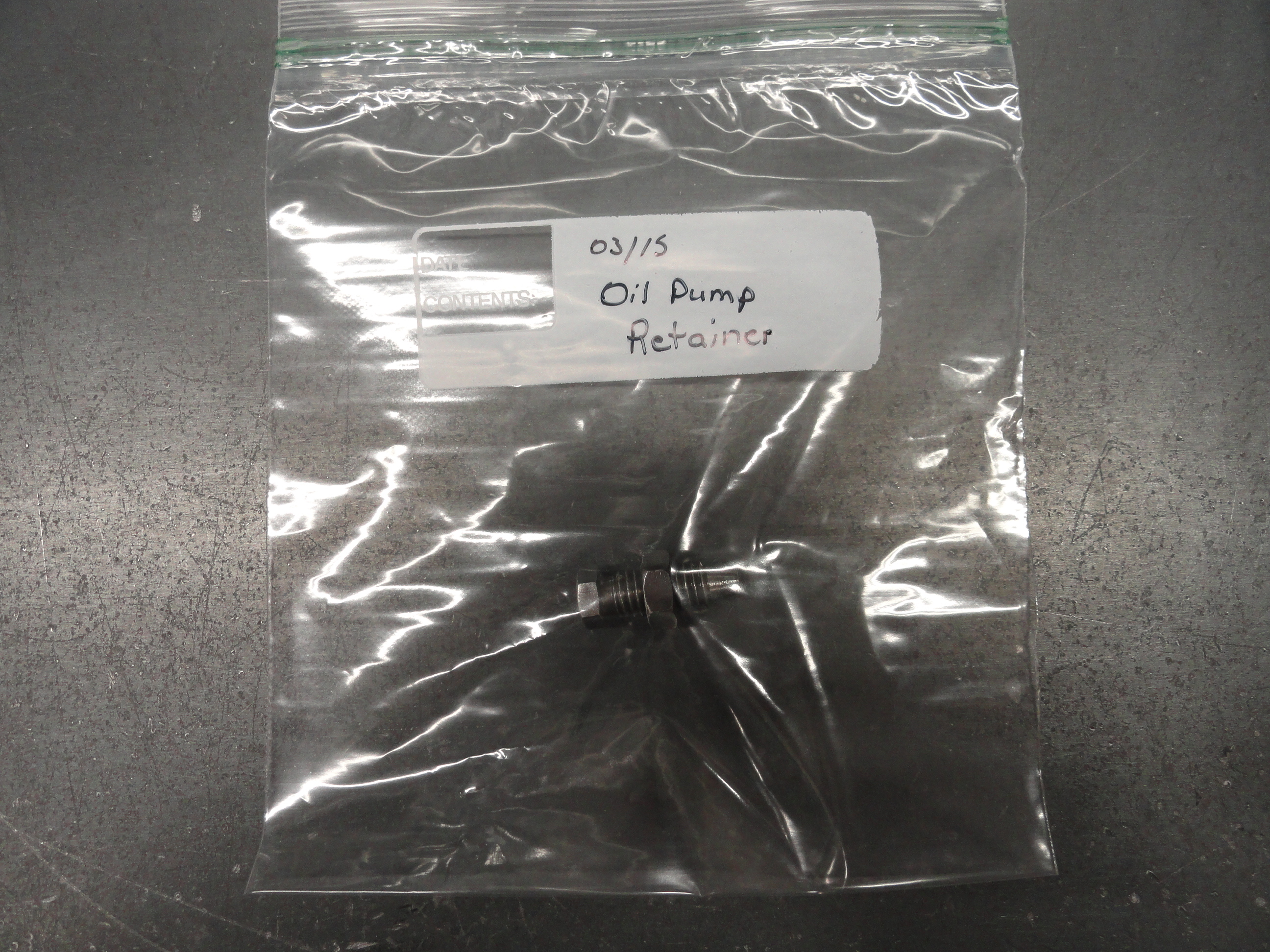
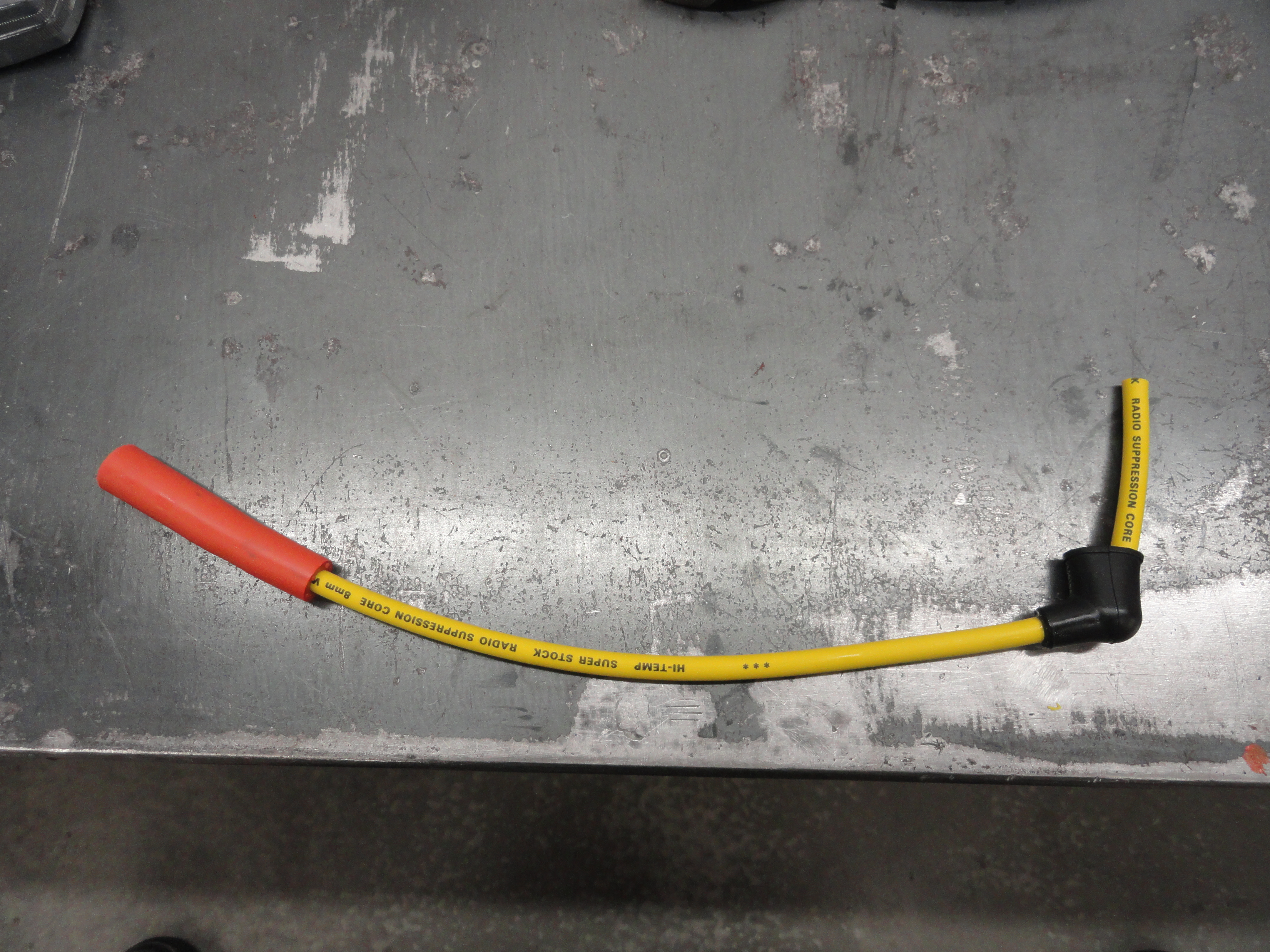
Your engine will not be all apart in boxes. So, since we are doing a complete rebuild and do not care about the current timing of the engine, remove the Distributor, plug wires, Spark Plugs, Coil, Road Tube, Starter, Generator or Alternator, Water Pump, Carburetor, Intake and Exhaust Manifold, Valve Cover, Lifter Side Cover. Organize these sub-systems carefully keeping the hardware separate. Separate the hardware, putting things in labeled ZipLock Bags. We will address how to restore these sub-systems later in this Article.
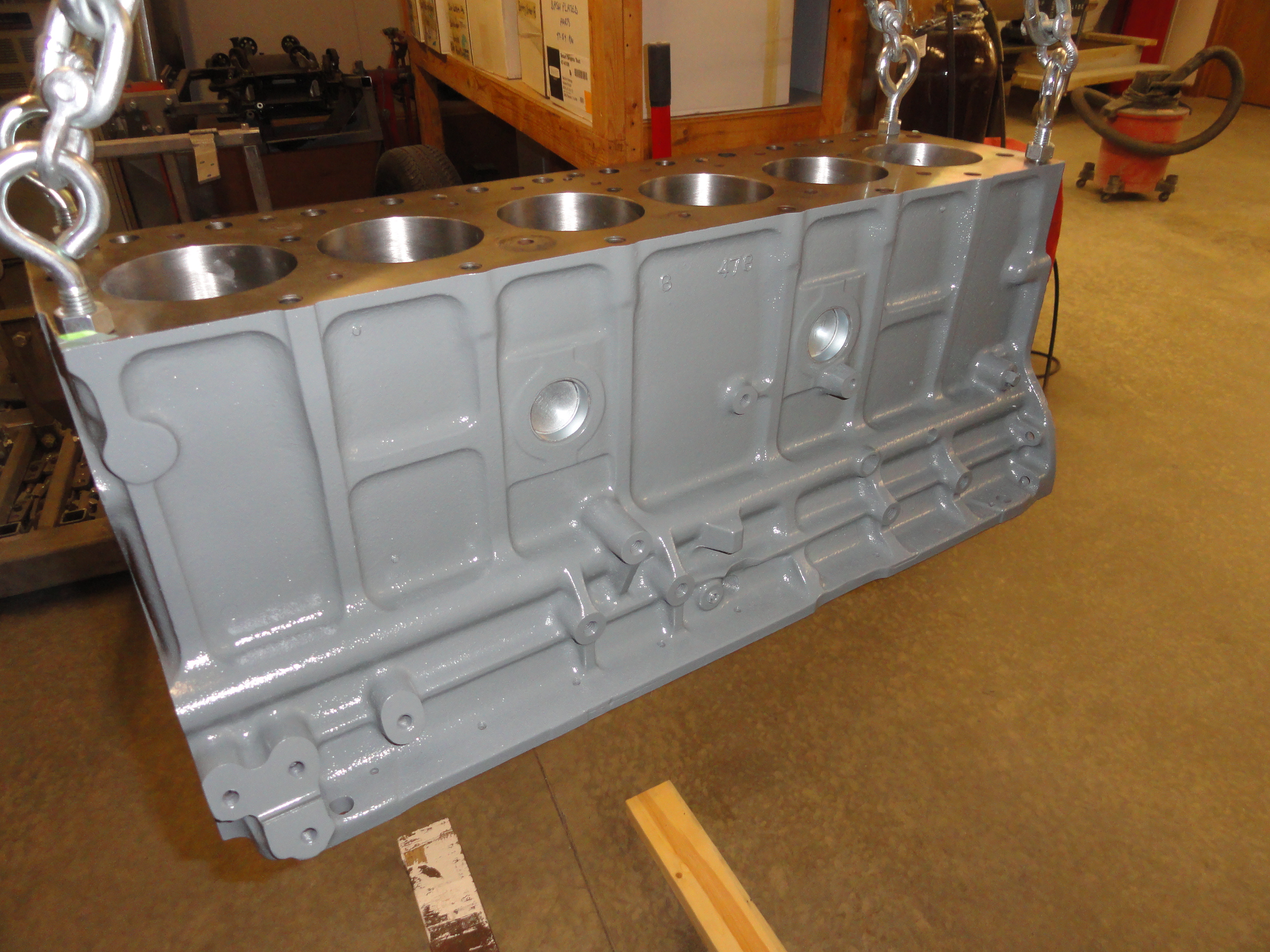
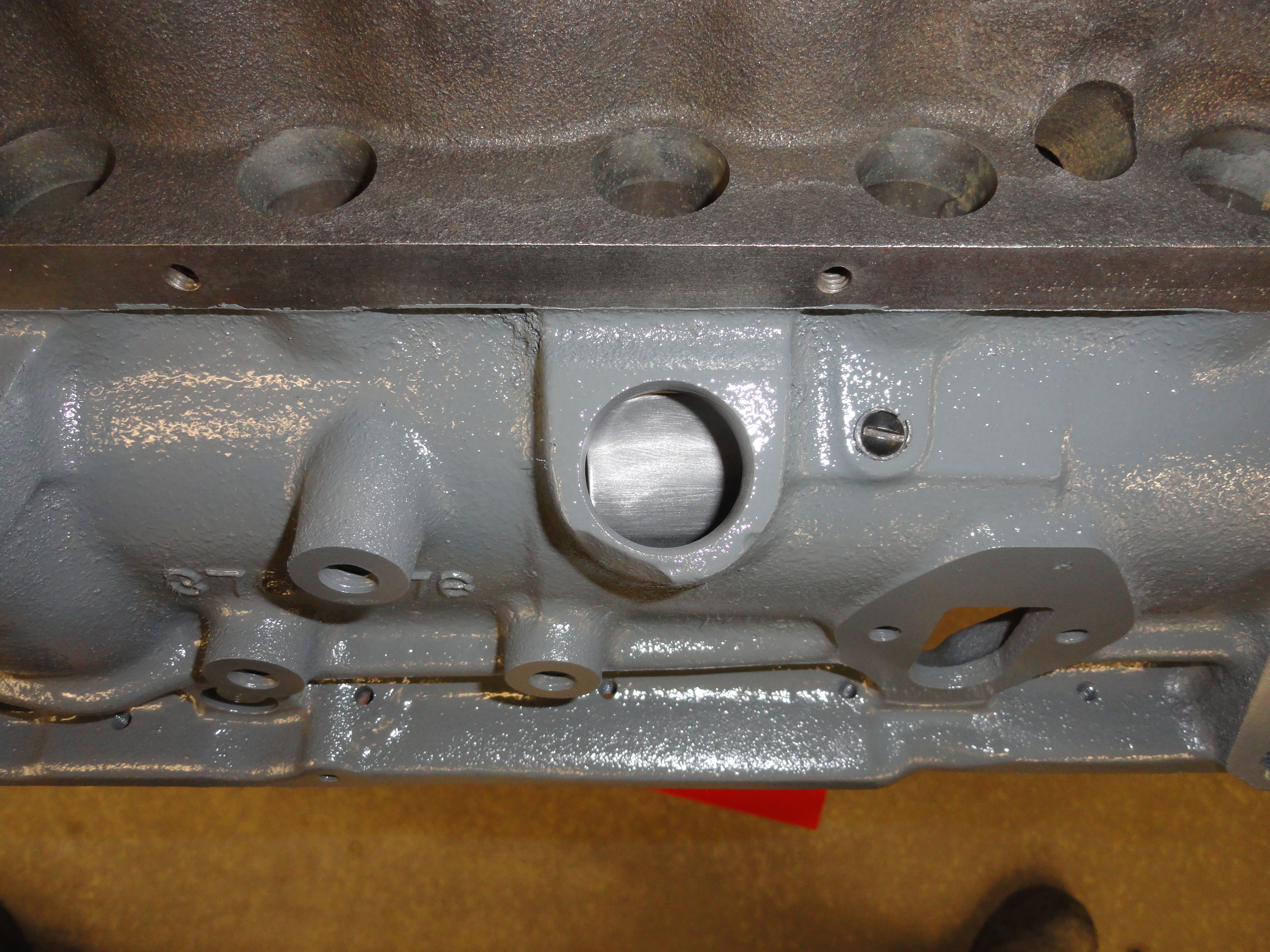
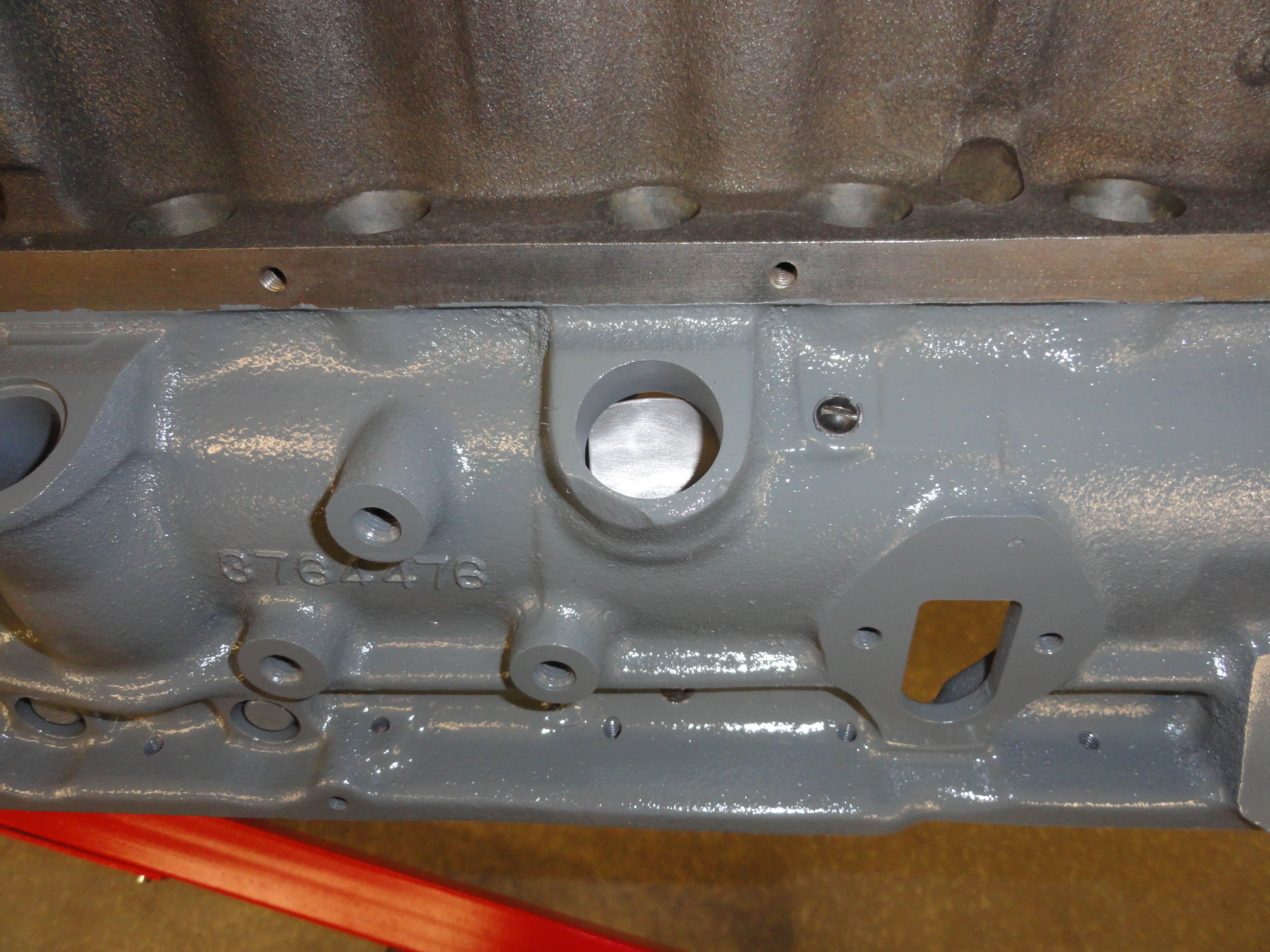
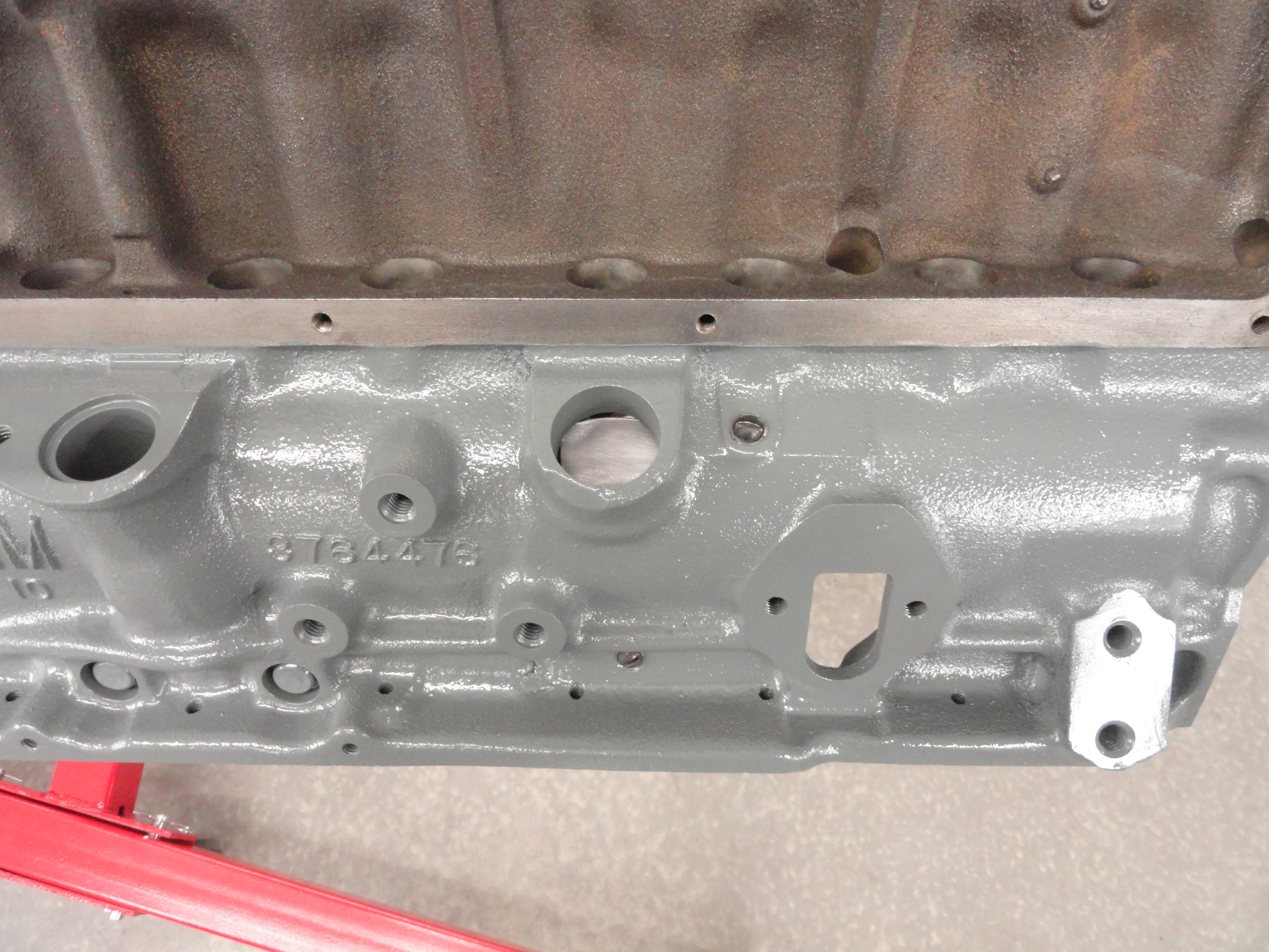
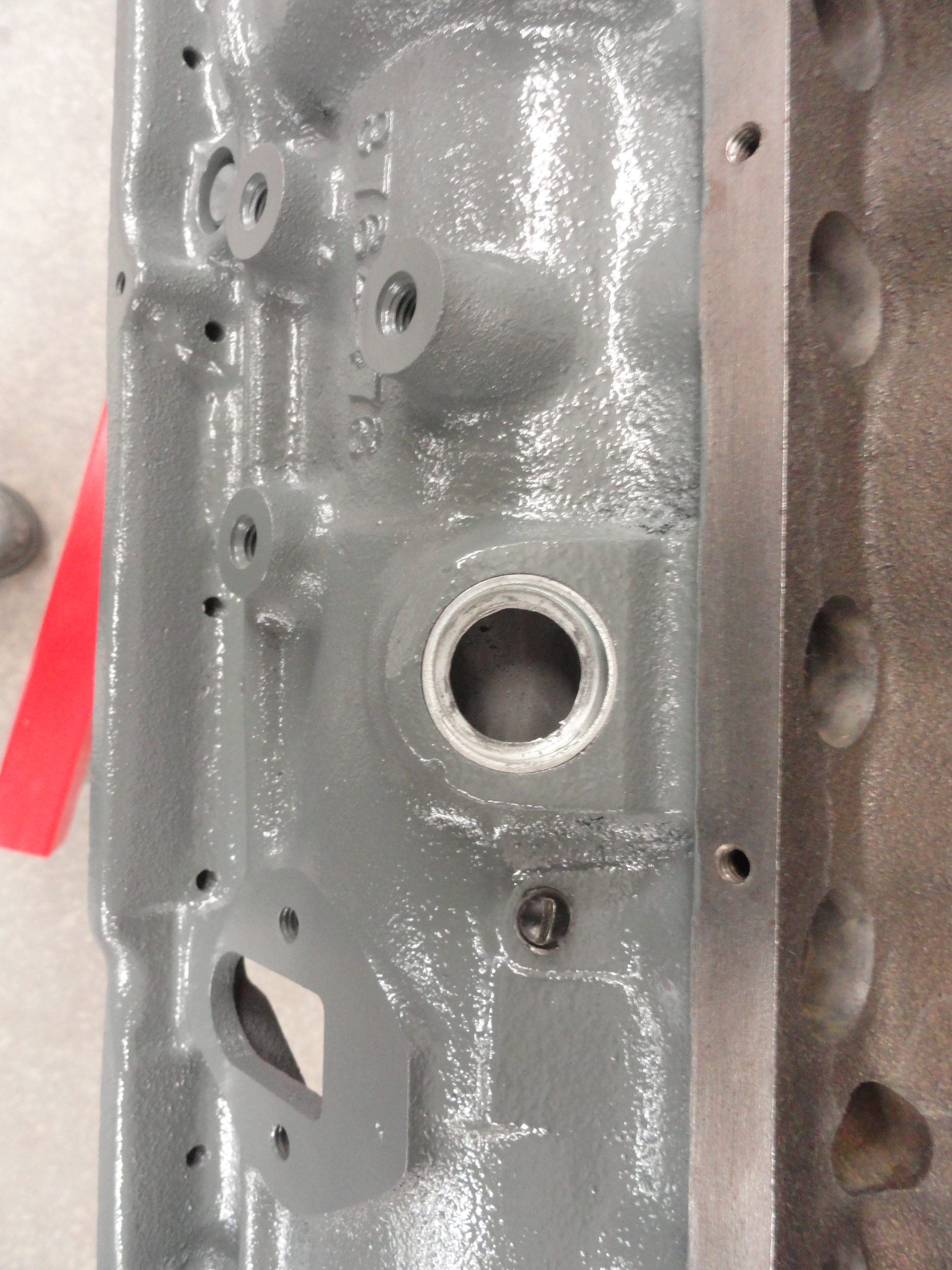
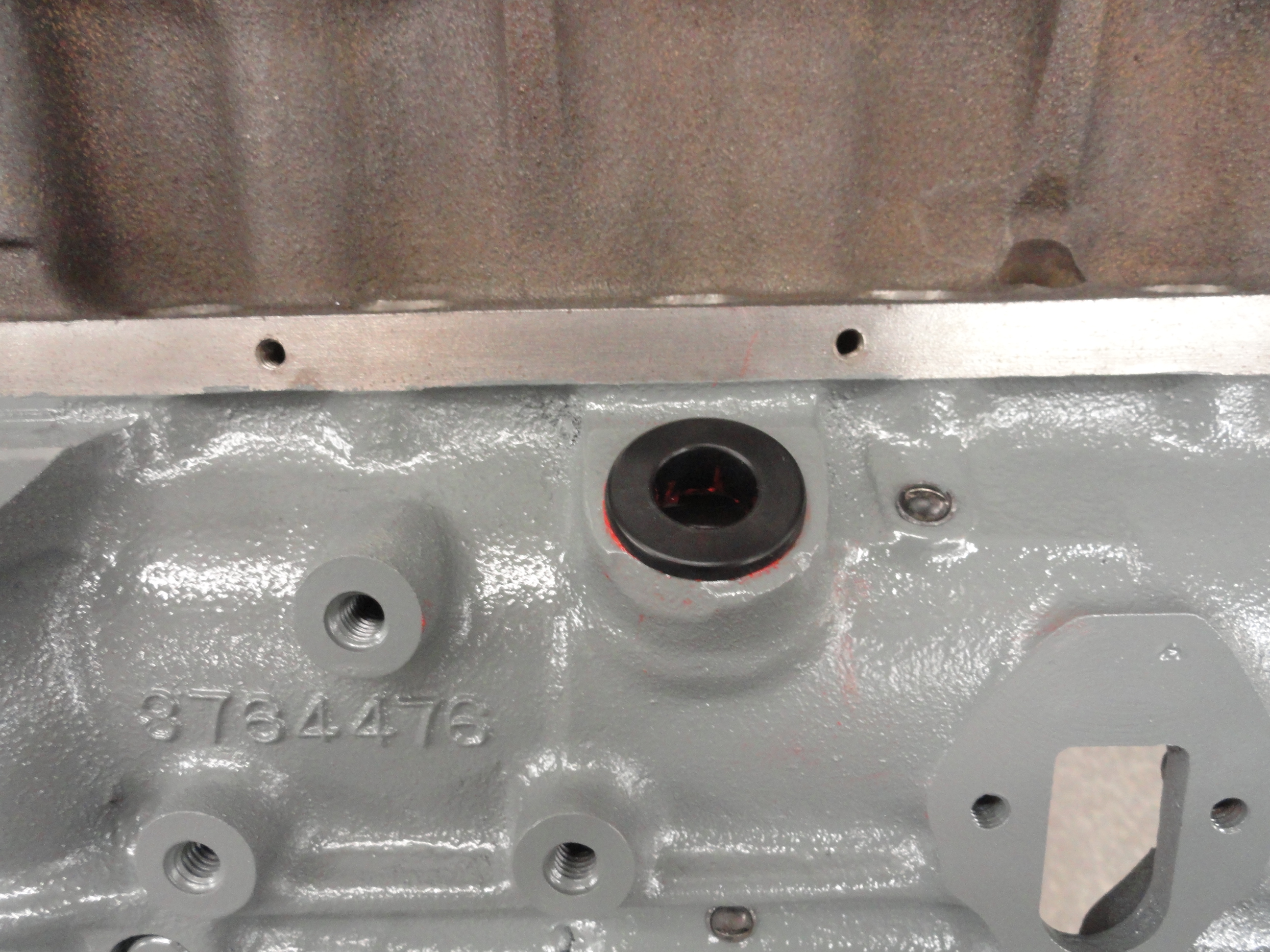
To identify any GM engine from 1942 though at least 1964, you can go to The Casting Numbers Database. The following text on how to identify the engine we are working on presently will give you the clues you need to identify yours. Let's start by properly identifying this engine. Below the distributor is the casting number, 3764476. This engine was built between 1959 and 1962. Then just above the starter is another clue CON3 (the third conveyor at the factory) and B 28 9. B is February, 28 is the day of the month and 9 is the year. So we know this engine was built on February 28, 1959. In other words, The first letter corresponds to its month, A through L (A meaning January, L meaning December). Now let us take a look at the serial number that is stamped on the flat part of the distributor deck. that number is F302B. That number breaks down as follows "F" means the engine was made in Flint, Michigan. 3=3rd month=March. 02=day of month=3rd and finally B=model/series=car engine with Powerglide (Hydraulic Lifters). So mark your calendars because March 2, 1959 is the reason for all this Hoopla! I don't know the guys name who made it, but this is about as good as it gets! When you stop and think about it, they must have been very busy at the time since the serial number only lagged the casting of the engine by 2-3 days!
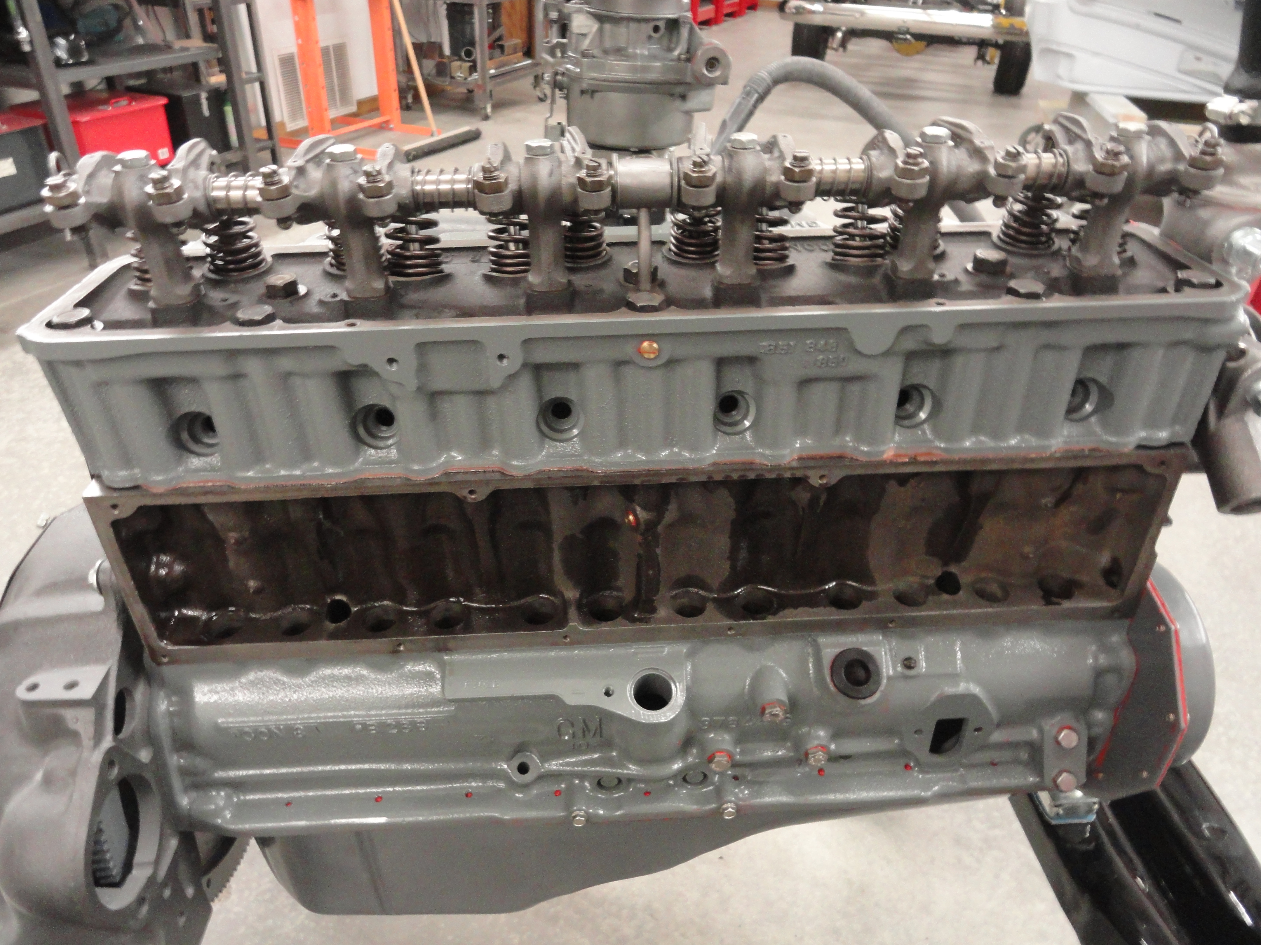
The Head follows a similar numbering scheme. On the drivers side (left) on the outside, not covered by the Valve Cover, is the casting number, in this case 3836848. This tells us the Head was made between 1955 and 1962 and was used on Cars and Trucks. Then just inside the Valve Cover in almost the same location is another clue CON9 (The 9th Conveyor at the Factory), and about 4 springs to the right of that is another number H 3 0 which is the date the Head was made. H 3 0 converts to August 3, 1960. So, thinking about it, this probably isn't the head that originally came with the engine unless the engine sat on a shelf for about a year and a half. When you see the casting numbers ending in 848 you know you have the highest compression Head Chevy made for that engine. A great resource for clues on how to identify your Head or Engine can be found At Tim Ledermans Site
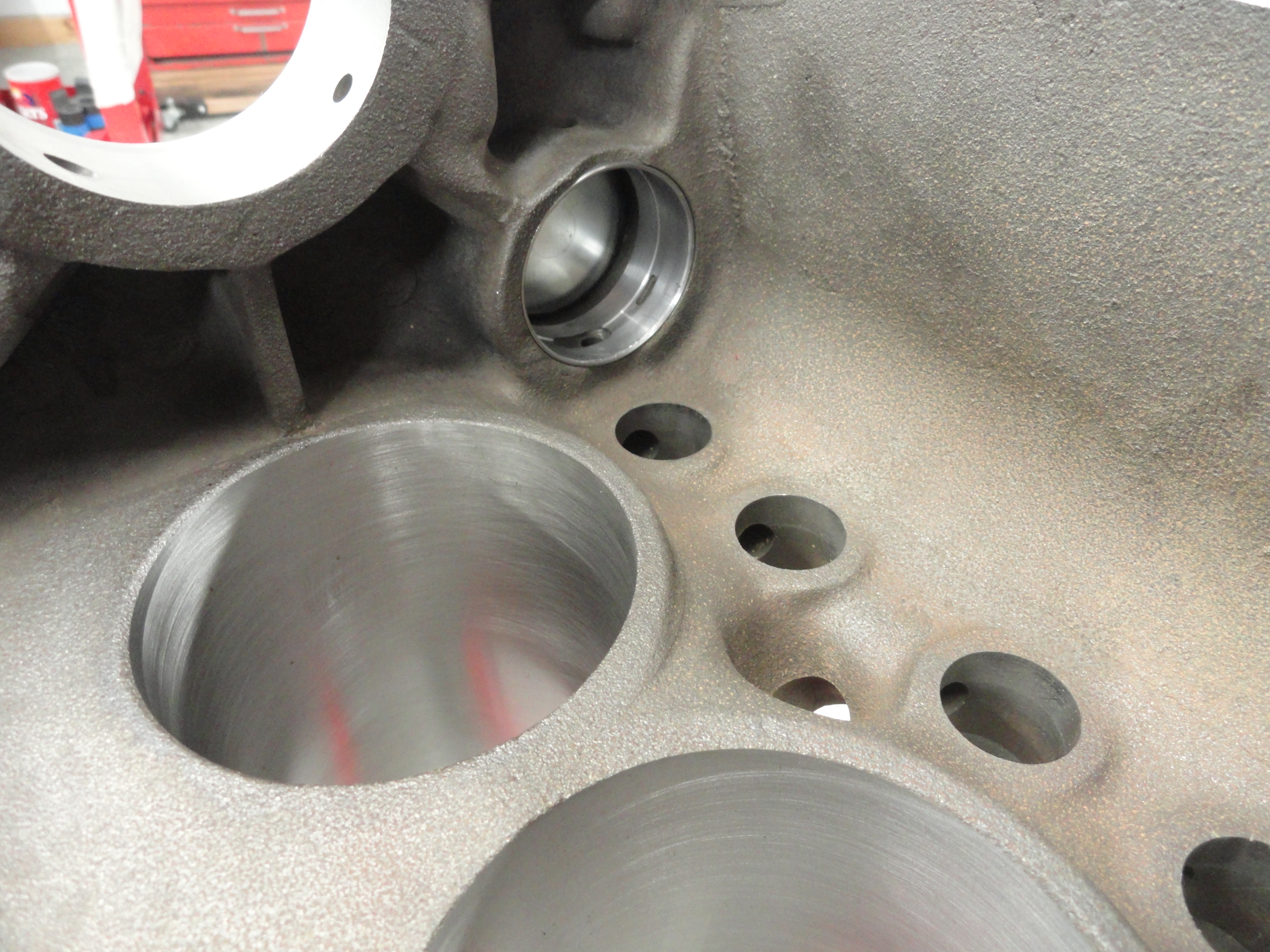
The engine we are documenting here is completely unknown. In your case, there might be a good reason you want to rebuild it. One good indication an engine is in need of a rebuild is excessive Blow-by. This is obvious by the amount of visible smoke that comes out of your valve cover cap. There shouldn't be any. This could be Valve Adjustment, or worn Piston Rings. Another good way to check the condition of your engine is a compression test. This is really beyond the scope of this article since any number of things could cause your engine to misbehave. What we are talking about here is the quality of the engine candidate. Is this engine worth the considerable expense to rebuild? Do you see visible cracks in the water jacket or anywhere else? Do you have any documentation that would lead you to understand the cylinder bore size that was done at the last rebuild?
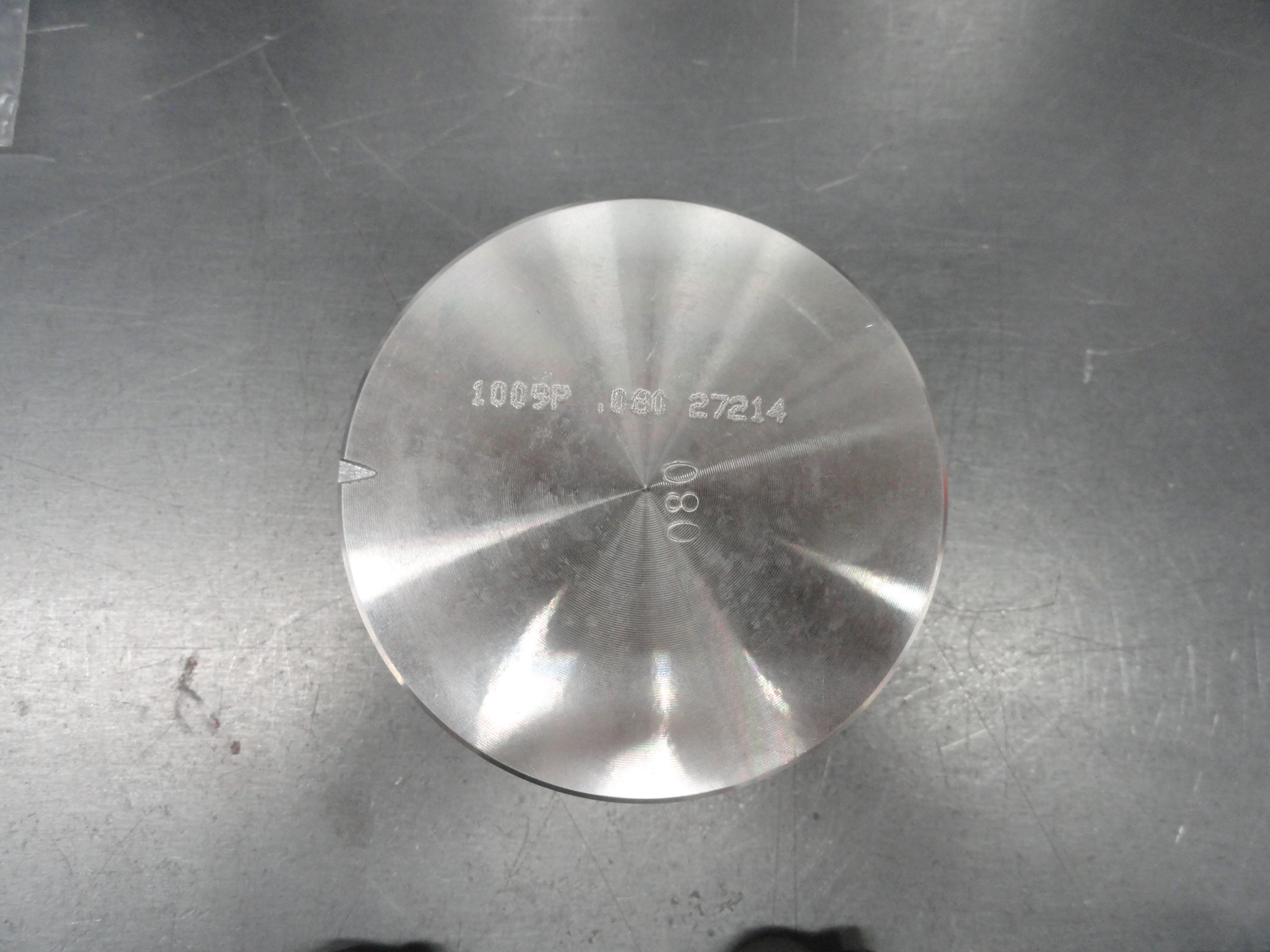
Something rather interesting and could be important for you to know is that sometimes the piston has a number stamped right on the face of it. You can discover something very important the minute you remove the head of an unknown engine. Wire brush away the carbon and dirt from the center of the top of the piston. If you see a .10, .20, .30, etc., on the piston, that tells you the last cylinder bore size. If it says .60, you are getting very close to the last bore size that is available for these cylinders. This may be a prohibitive factor for you since it costs just as much to do the first overbore as it does the last.
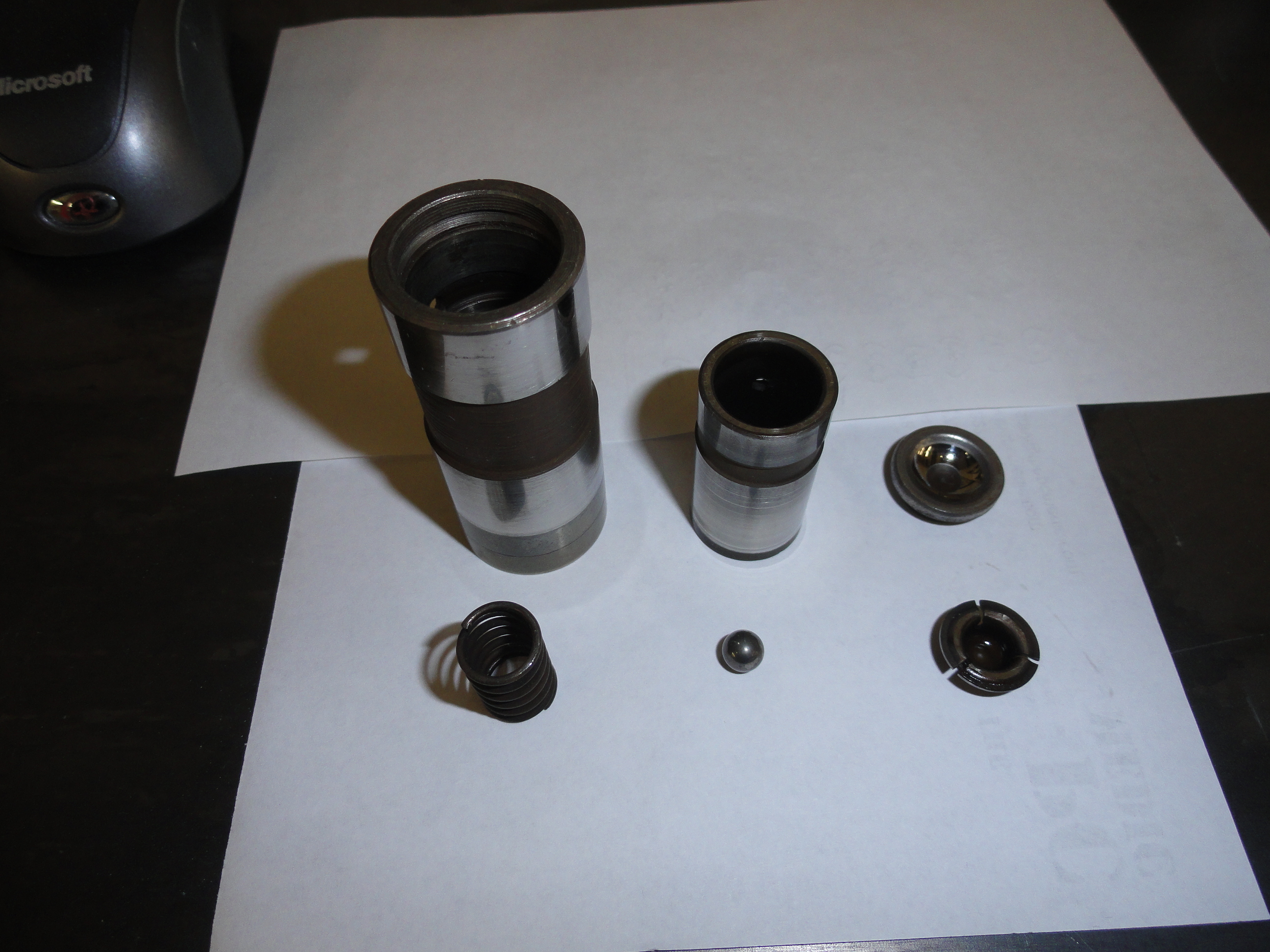
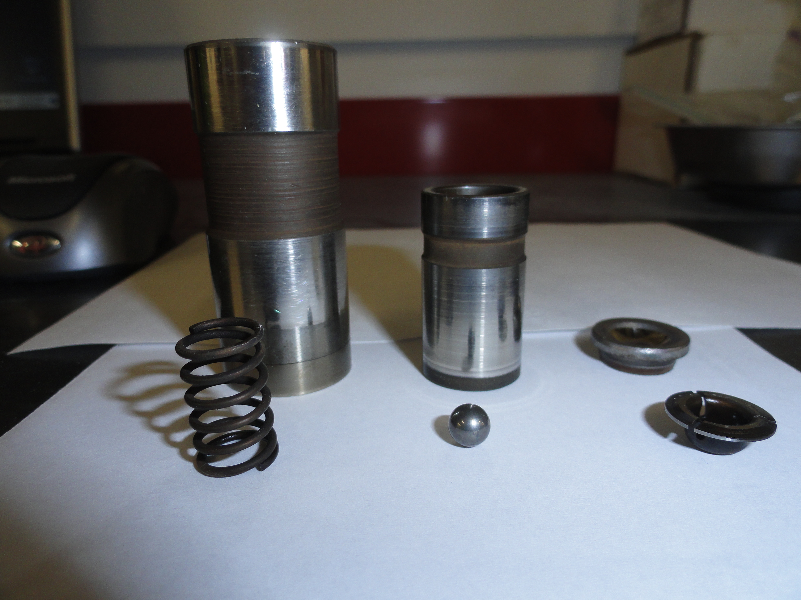
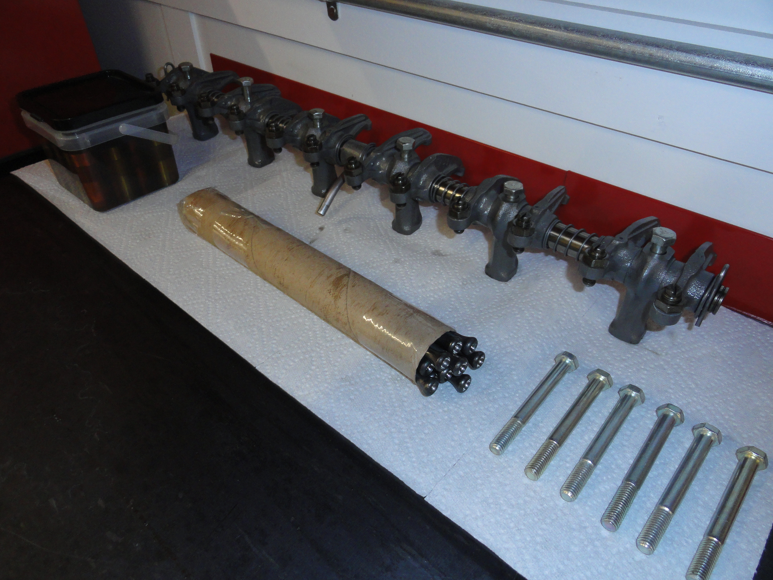
So this particular engine has hydraulic lifters. I personally like that even knowing that an argument could be made that they cost horsepower, because the engine is very quiet and runs very smoothly without much adjustment. Looking in the box, I find the 12 lifters for the project. Three of them are missing the retainer springs and the caps and there is stuff are all over the bottom of the box. Since Hydraulic Lifters are expensive let's see if we can save them. After a little research I learned that I can take them to a machine shop and have them surfaced so that they run against the cam as good as new. I will NOT use them if the machine shop expert says to buy new ones. But to get there, let's clean them up a bit. And the fun begins!!

Before we get our hands dirty, let's think about how to best proceed in addressing the 60 years of gunk and crud that is most
likely there for you to deal with. Thanks to some fellow enthusiasts from various forums around the world, here are a few nice
ideas.
There are many tools required for this job. As we address each system, we will update this list. Where possible I will add a link to a picture of the item.

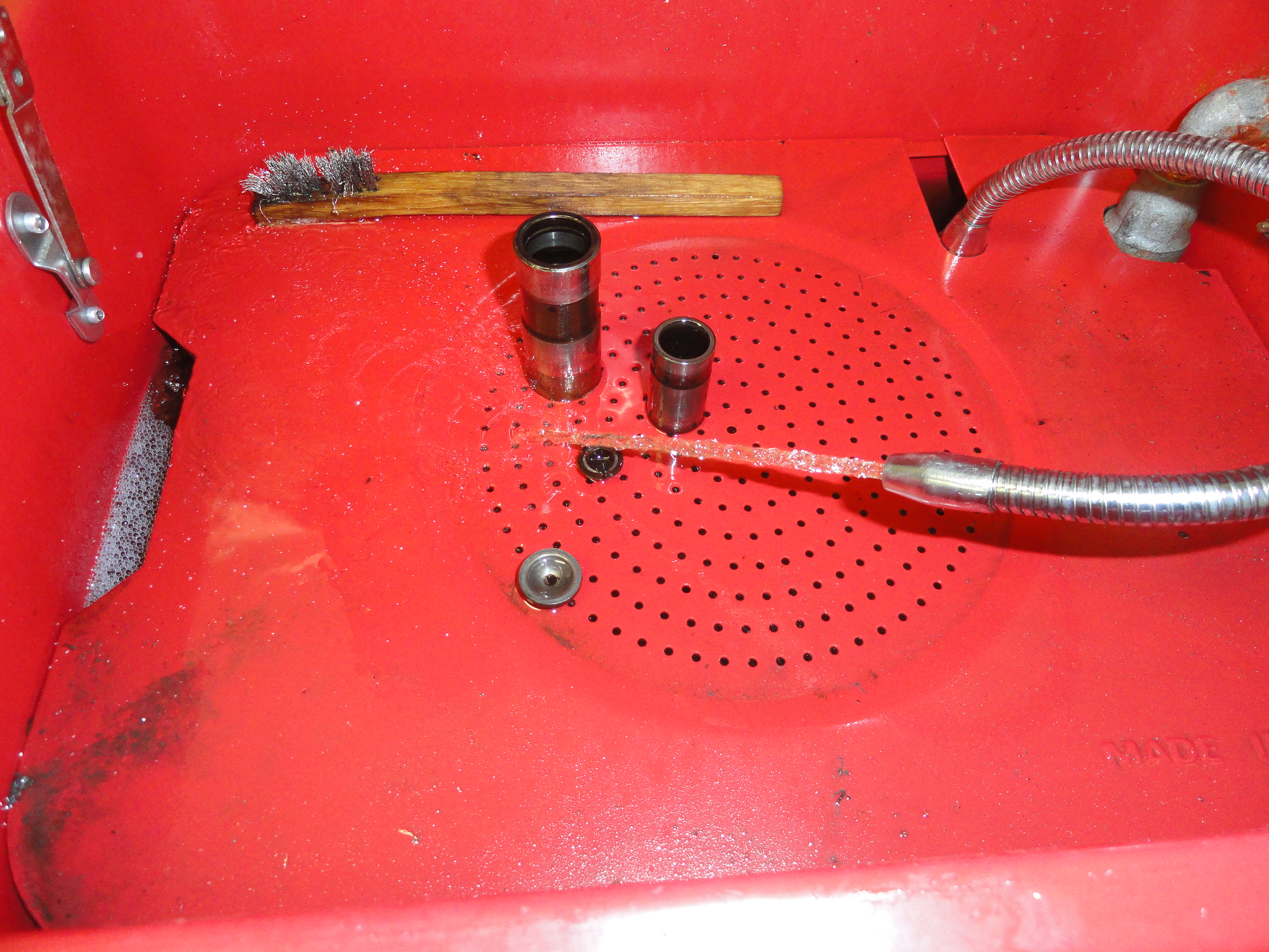

I just loaded each lifter one at a time into my little kerosene parts cleaner making sure to keep the parts together and not mix them with any of the others. The first three didn't have the retainer clips so I substituted a 3/4" snap ring retainer from one of my StoreHouse boxes. The edge of the retainer may need to be carefully ground down so it is away from the push rod, but it's a very solid fix.
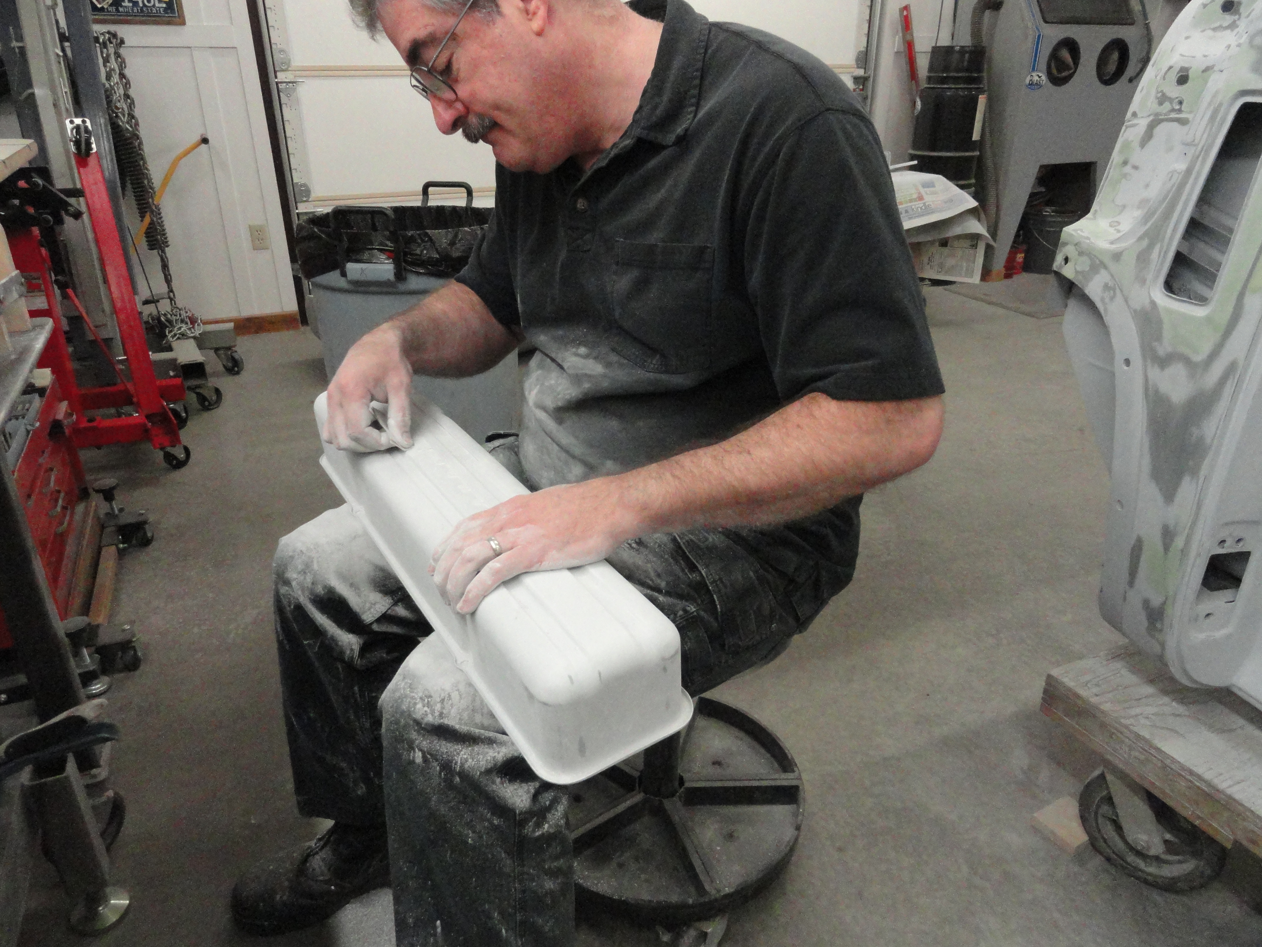
Once the parts are cleaned using Kerosene and a soft brush, I let them soak overnight in Simple Green. This removes all of the petroleum
based contaminants and you start off with fresh metal. I used a soft green scotch-brite pad for cleaning, rinsed each part carefully and
applied some motor oil to all of the surfaces. These lifters look like new. Let's put them together. I cannot take pictures and work
at the same time when I have oil all over my hands so I will describe the procedure.
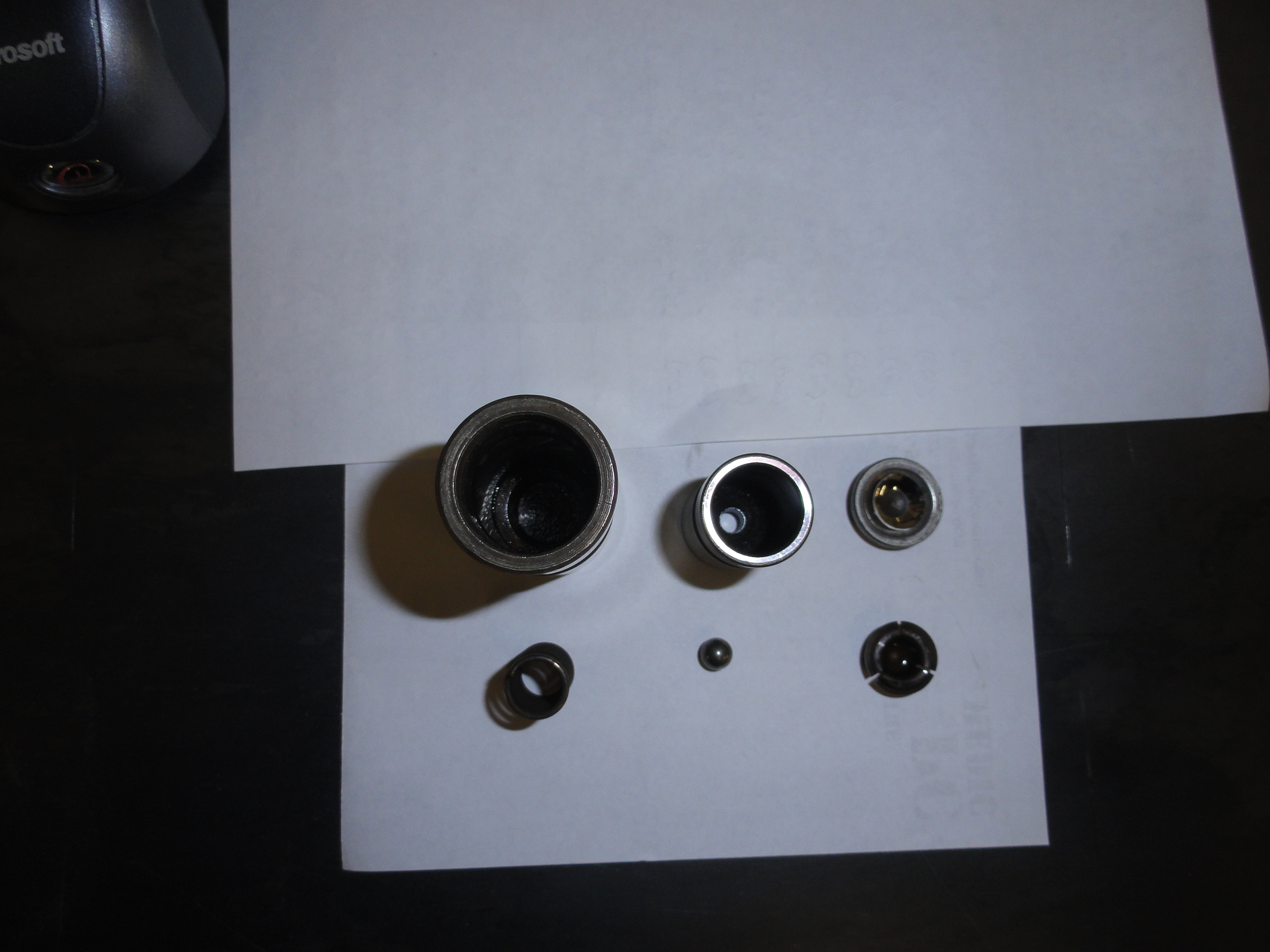
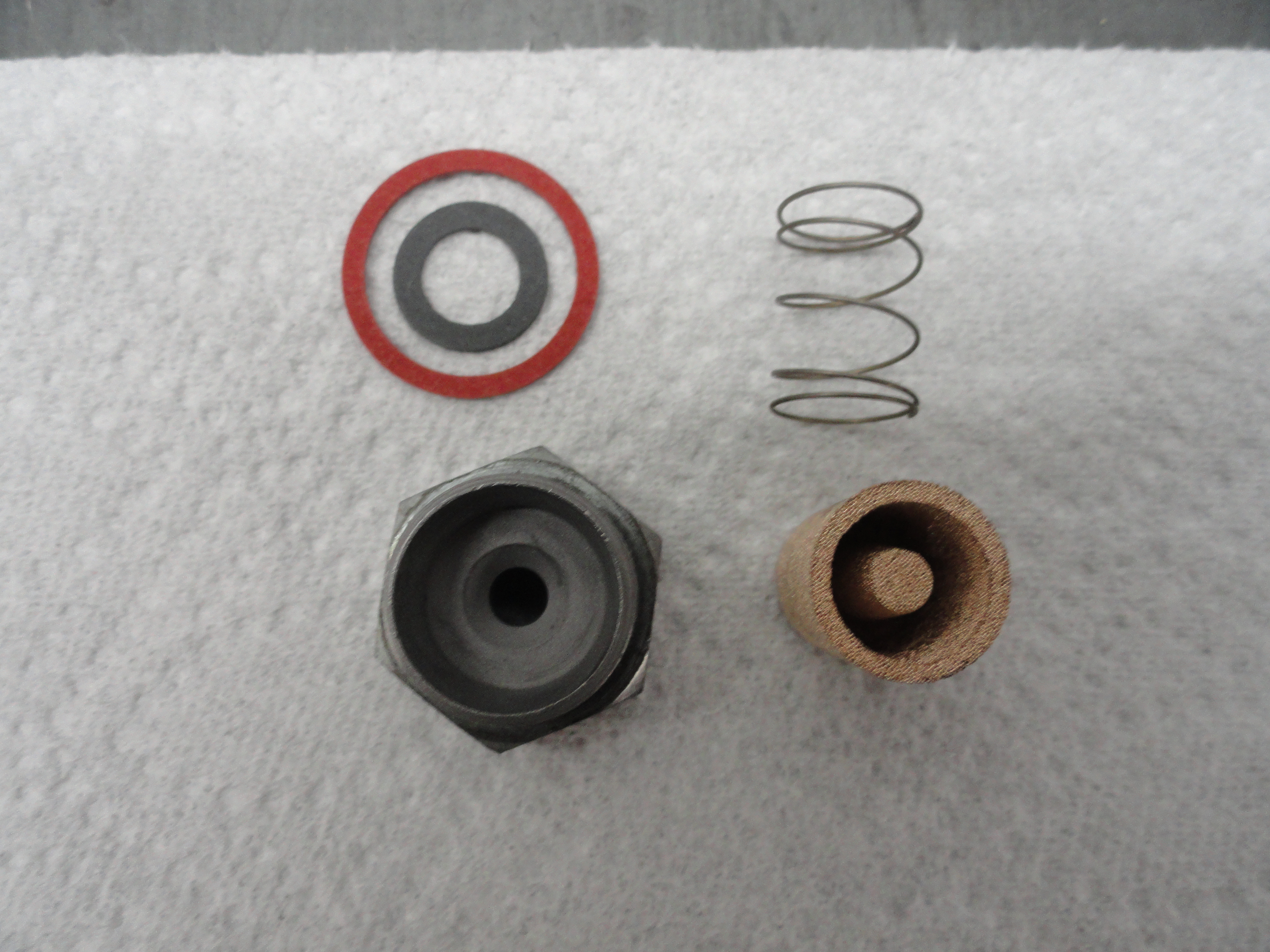
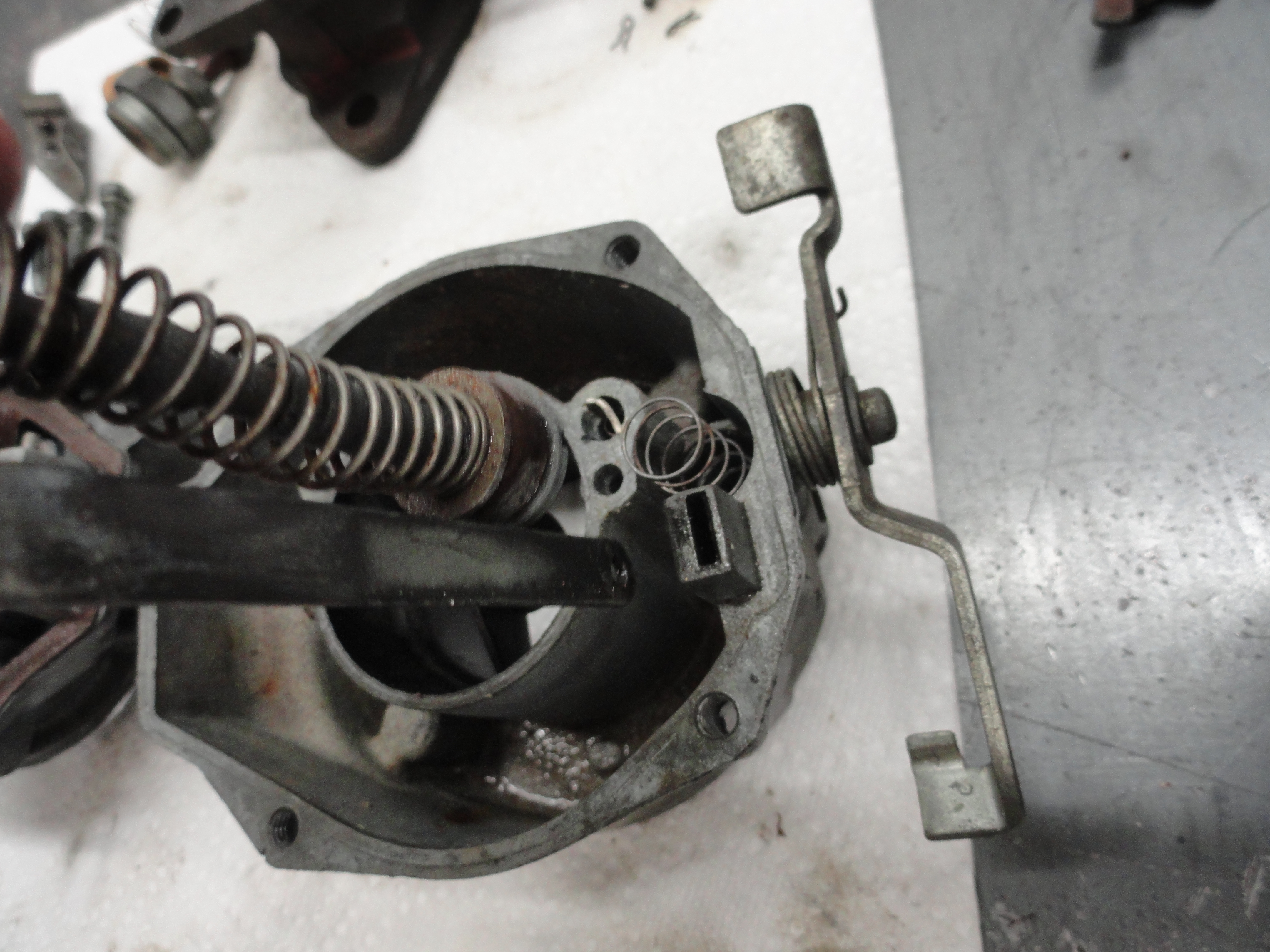
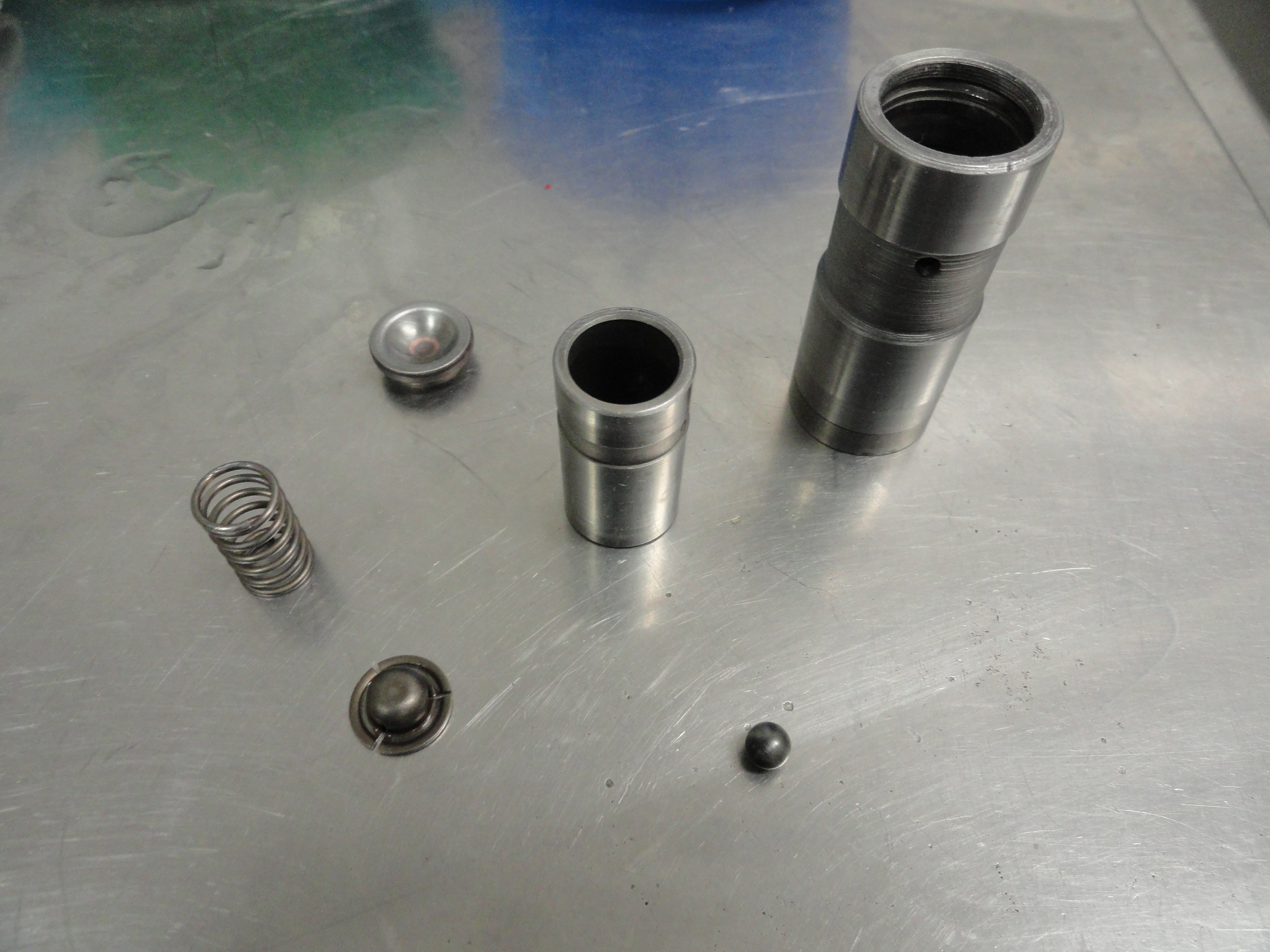 The picture on the right shows (from left to right):
With oil all over everything, including inside the Lifter Housing, turn the Inner Lifter Barrel upside down and place the ball bearing over the hole, then place the Ball Bearing Cover over the top of it. I like to drip a little oil over this assembly to sort of make everything stick together. Place the Tension Spring on top of the Ball Bearing cover. Everything should go together just as if it fits perfectly that way. If it doesn't you are doing something wrong. Now while balancing the Inner Housing, Ball Bearing, Ball Bearing Cap and Tension Spring in one hand, Turn the Lifter Housing upside down and gently twist it down over the assembly. It should be very smooth until you get some hydraulic resistance. Most of the resistance you feel is from air being trapped between the two barrels. With a very small, thin tool (I used the plastic straw from a WD40 can) push on the ball bearing just a little and you will feel the resistance just BURP away.
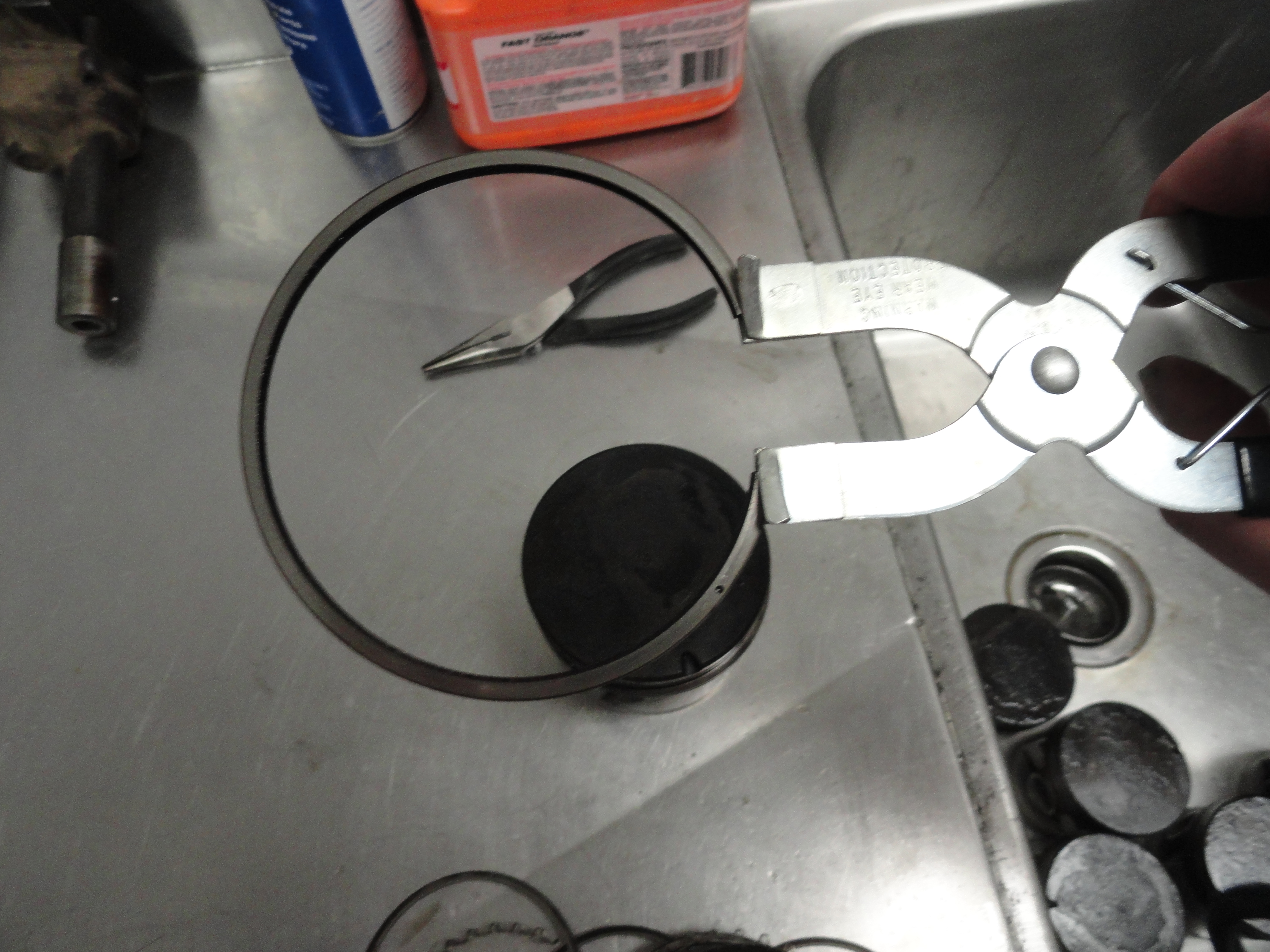
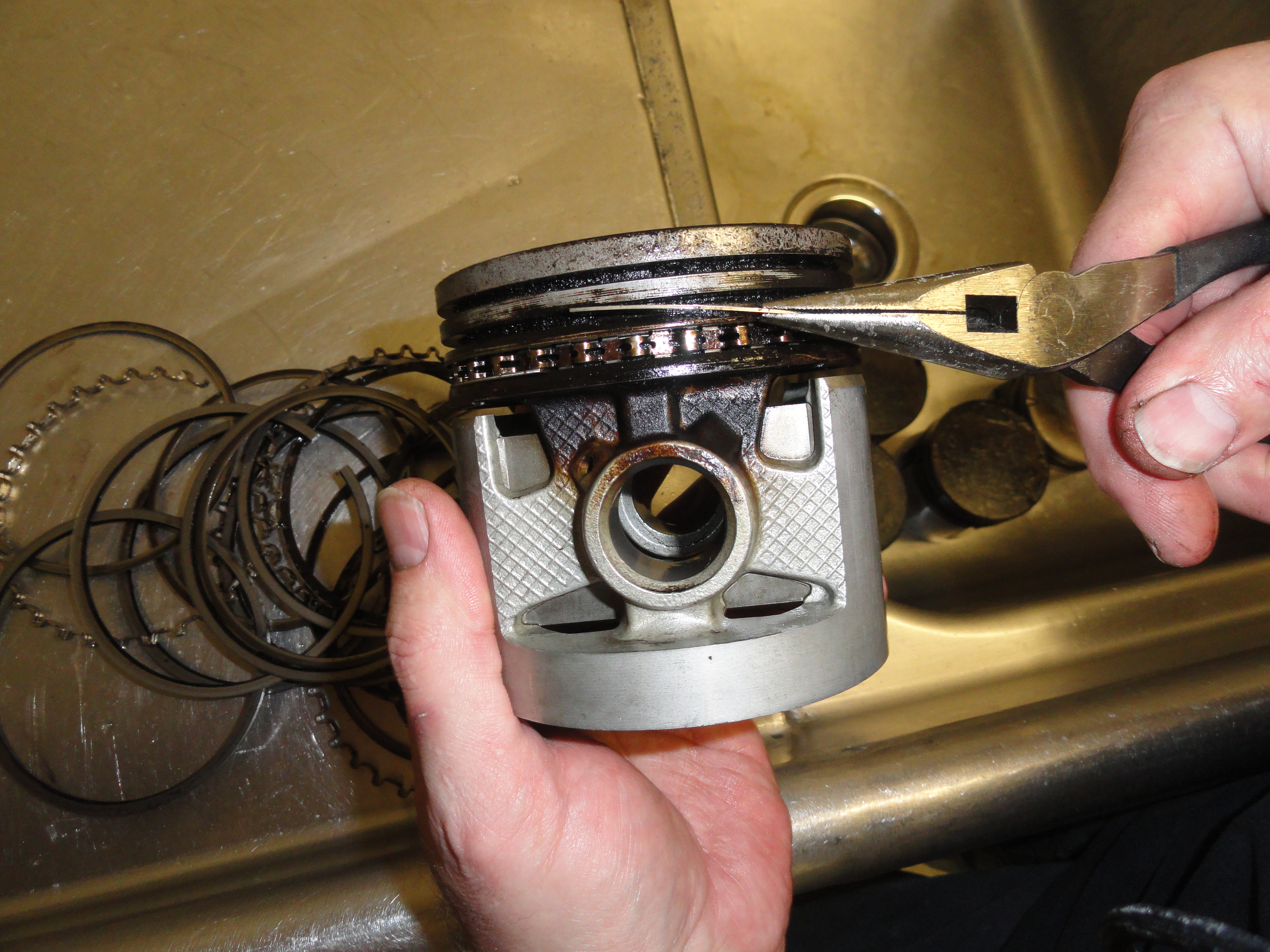
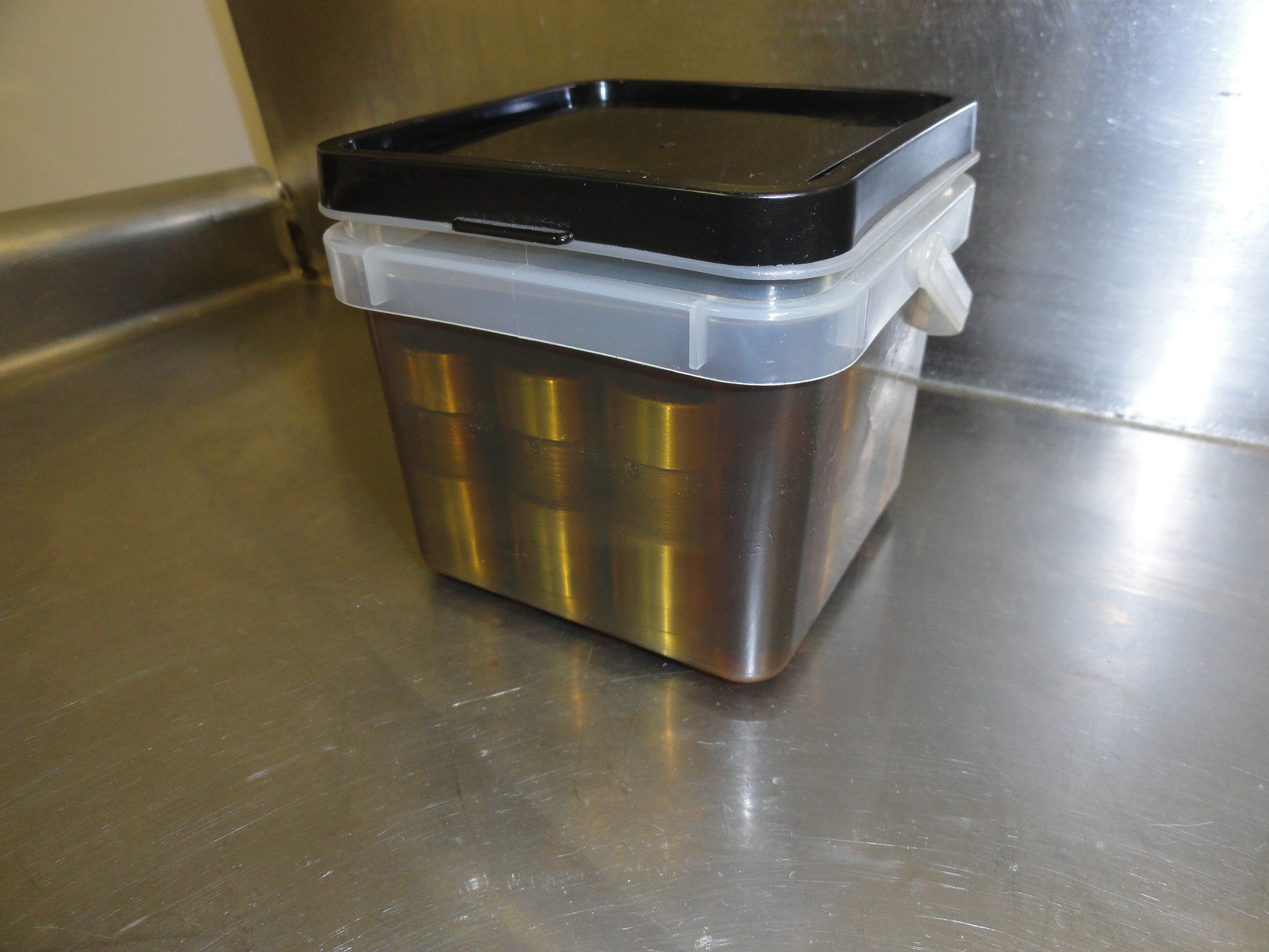
Keeping just a little downward pressure on the assembly, place it on a flat surface and fill the Inner Lifter Barrel to the top with engine oil. Place the Push Rod Cap over the top. You will notice this cap will push down below the surface of the Lifter Housing. Place the snap ring in the pliers and holding it over the Push Rod Cap, push down on the assembly using a push rod so that the cap is sufficiently below the surface of the Lifter Housing to get the snap ring to engage. Keep in mind, most lifters have their own retaining spring that is MUCH easier to install, but I am telling you this just in case you run into what I did! You should have one fully loaded, fully burped, serviceable Hydraulic Lifter. Now do that 11 more times! When finished, find a nice container that you can use to hold all 12 of them and be able to fill with engine oil over the top of the Lifters as shown.
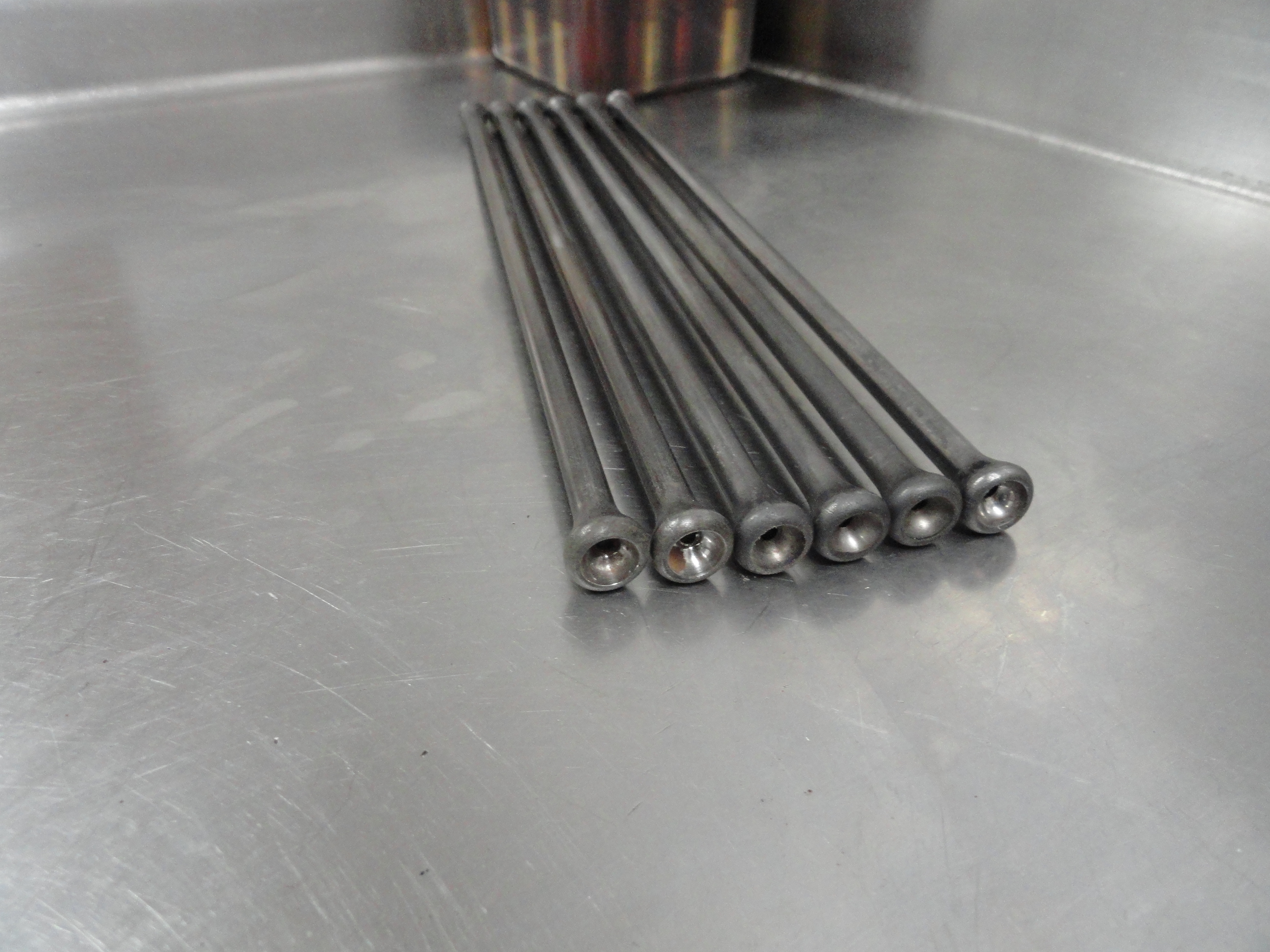
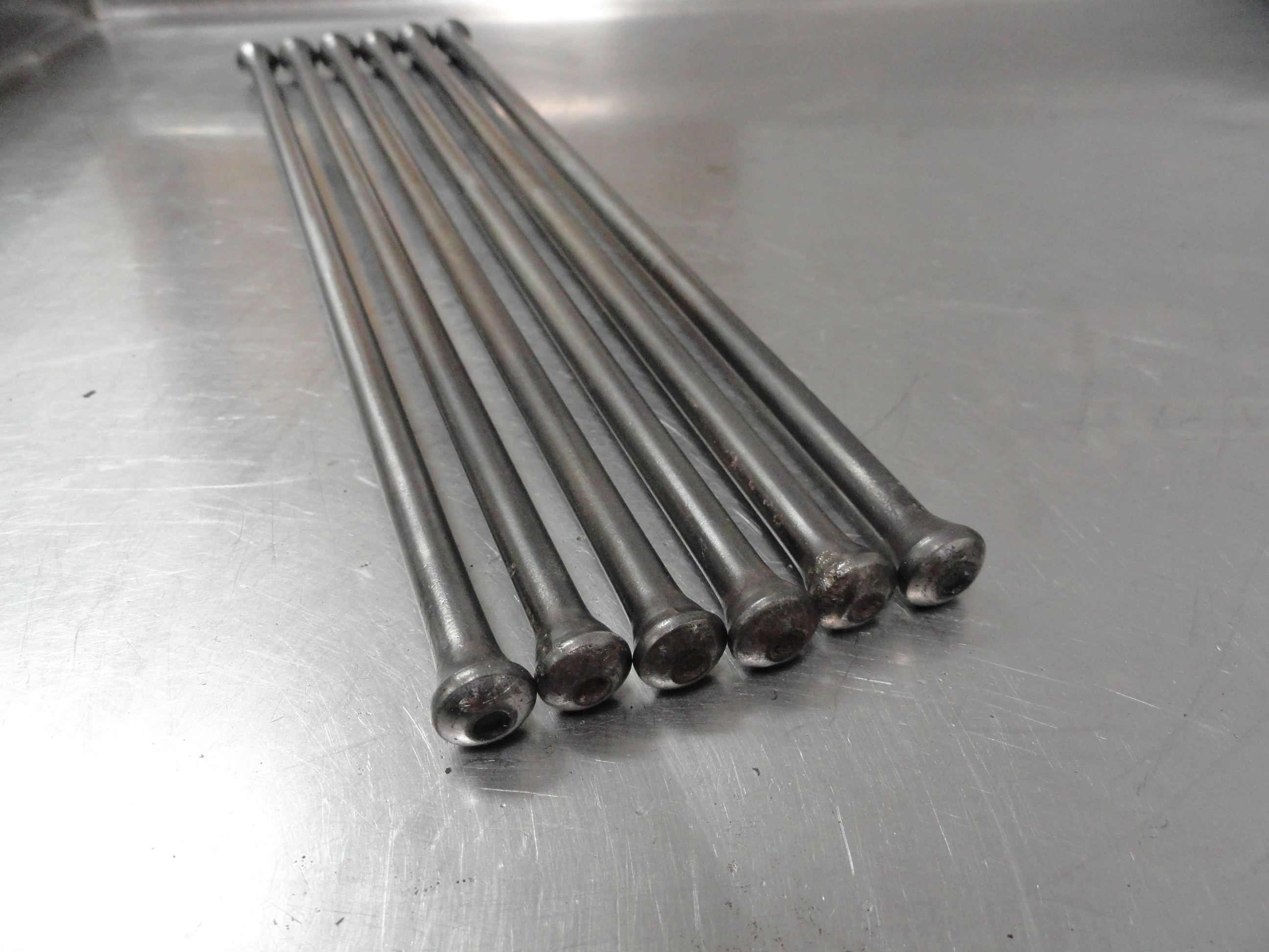
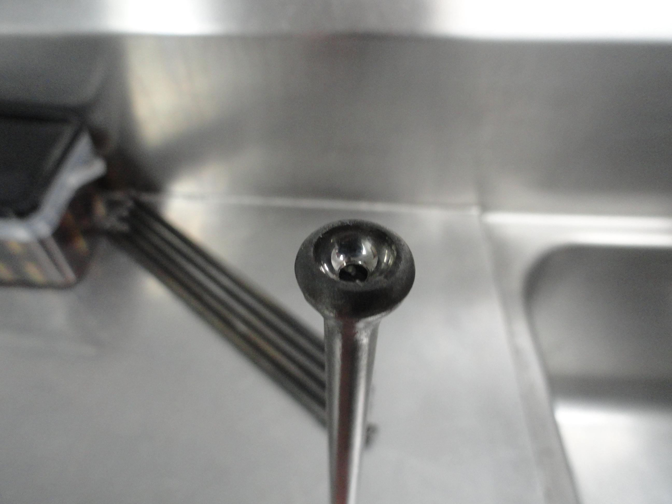
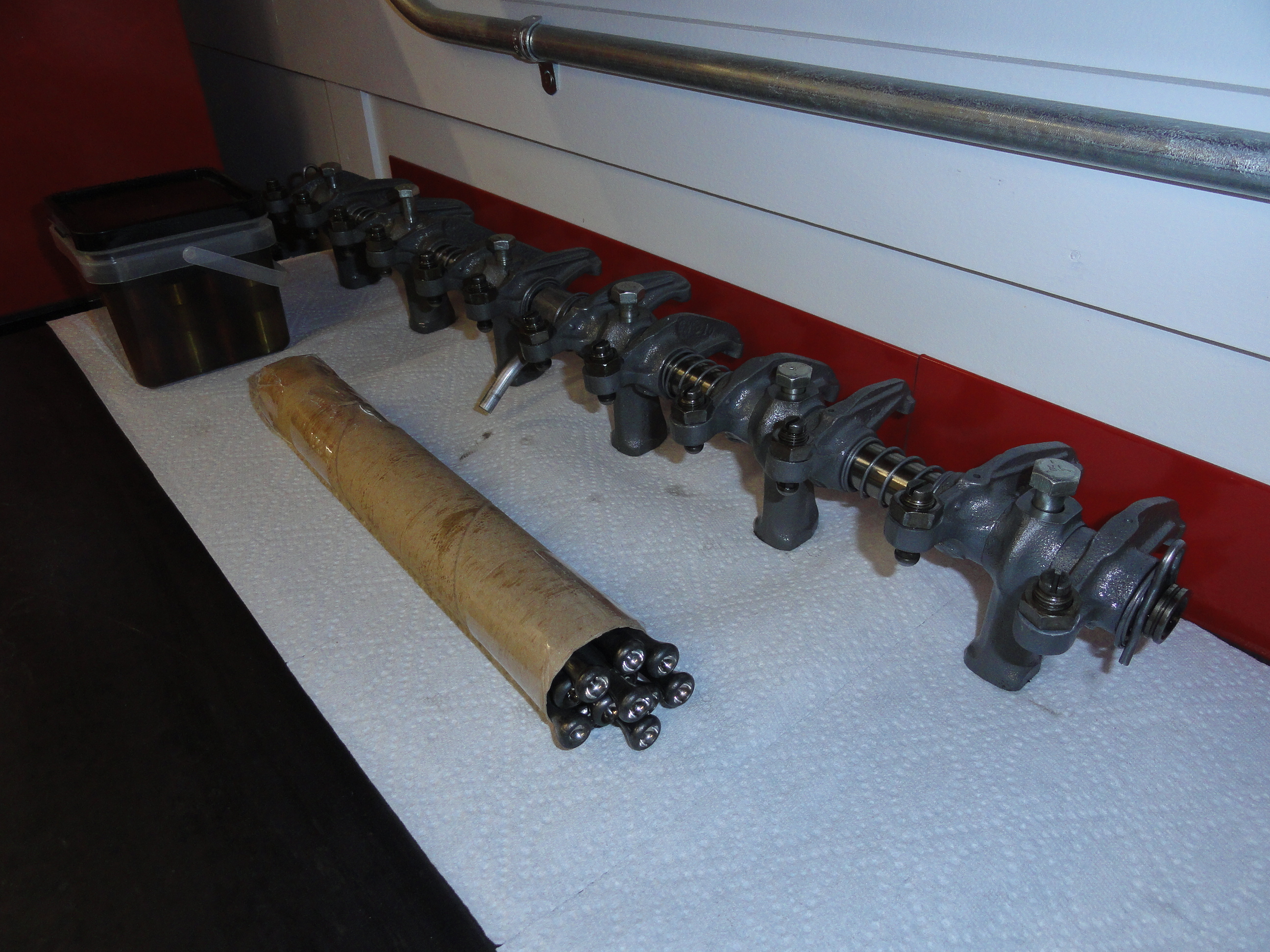
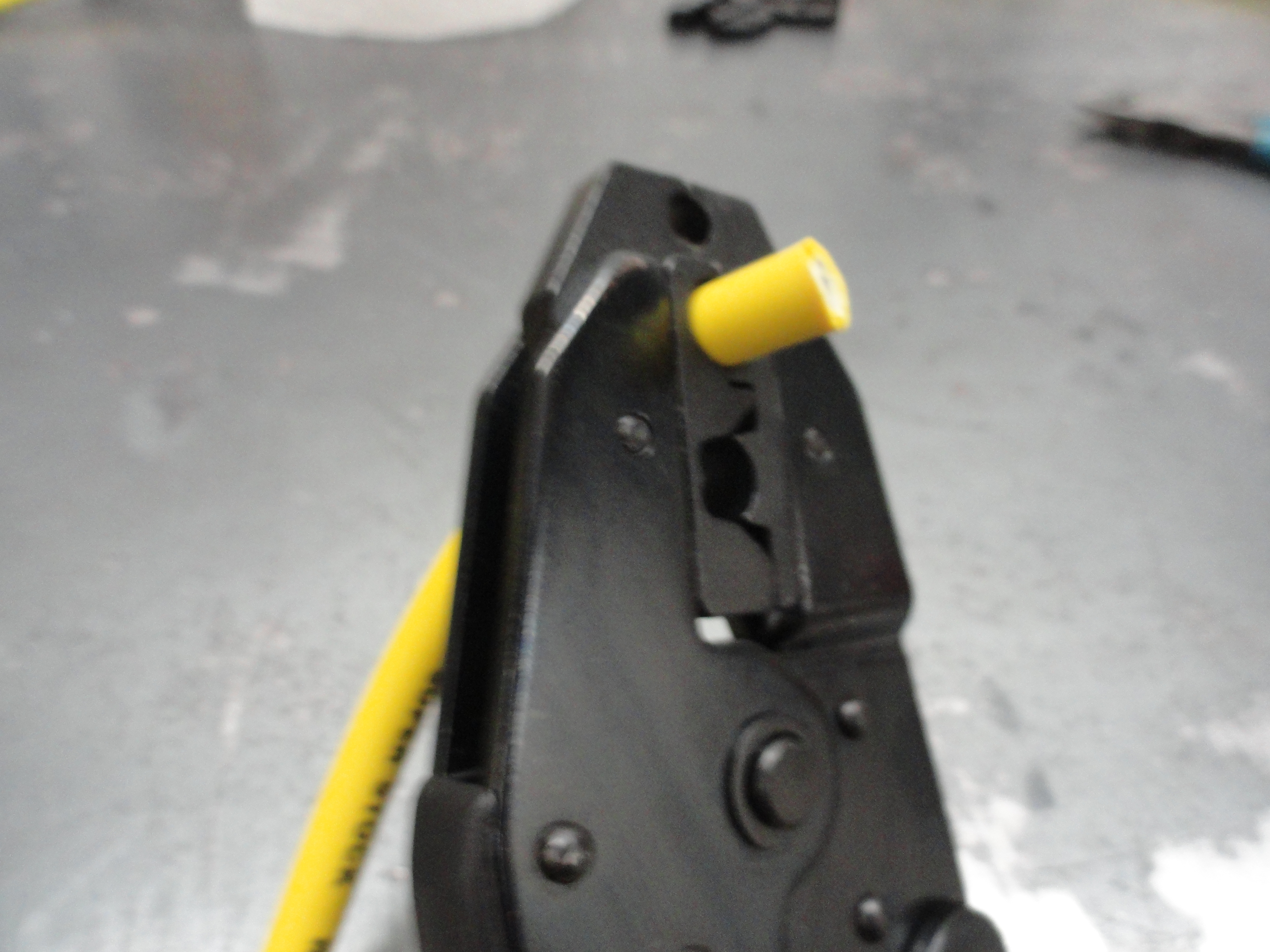
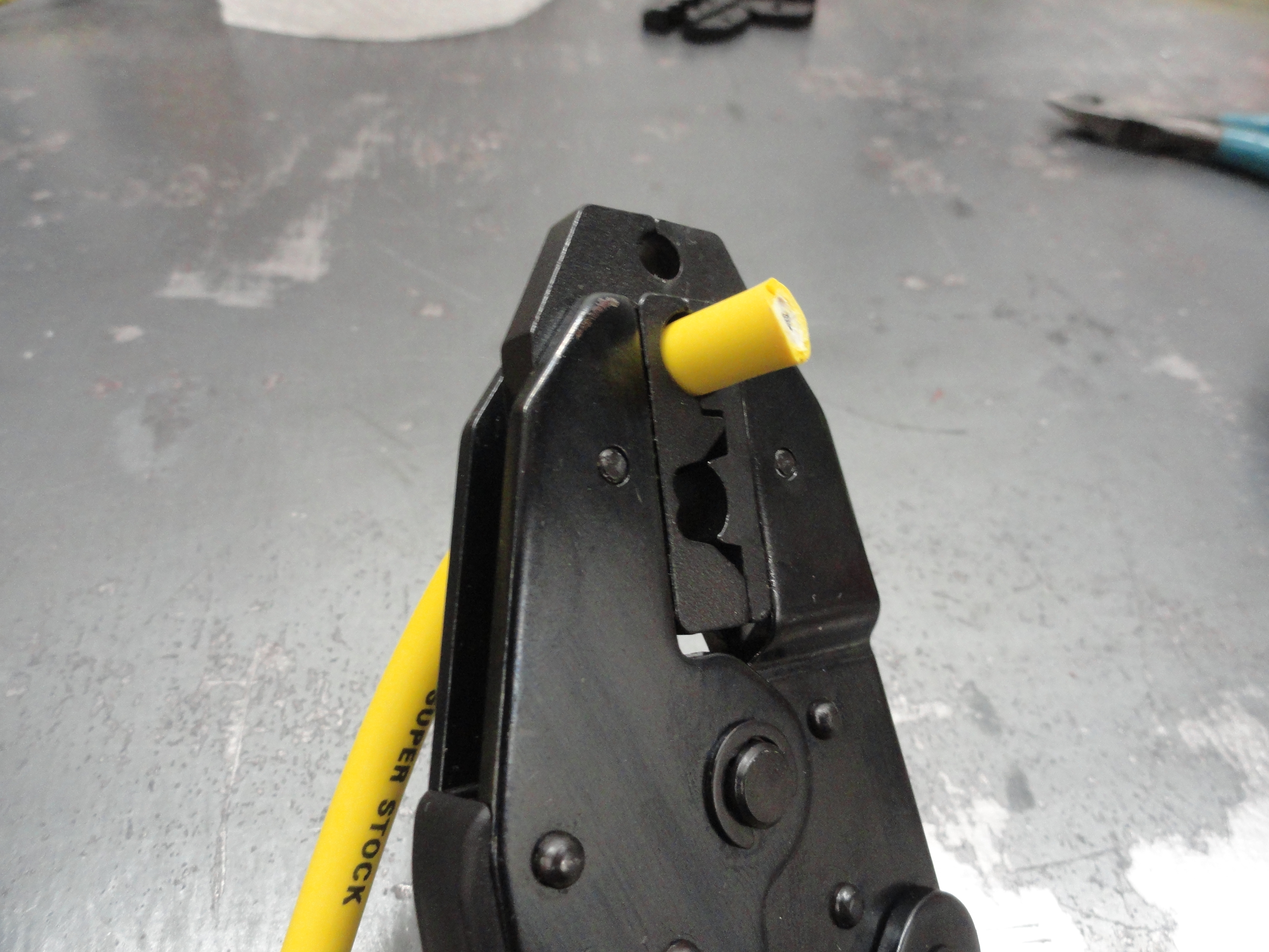
The Push Rods were also in the box. We need to test them to be sure they are perfectly straight and that each end is in the proper
condition to be used. To do this, find a perfectly flat surface (glass is good) and roll them across the table watching for any wandering or out
of straight condition. If they are not straight, do not try to bend them back, just get new ones. Next, carefully inspect each end
to make sure the little hole in the center is pronounced and clean. If there is any residue in the center, clean it
thoroughly so that its surface is shiny and smooth. I like to go the extra mile and Scotch-Brite the entire length and clean them up
really good. Test for straight one last time. That is the procedure, however, in this case, I was not happy with the condition of
about 5 of them. One had a very significant wear spot that actually reduced the diameter, the others were just slightly bent. Good
for me, I had a box of old push rods off these old Stovebolts and found 5 perfect replacements.
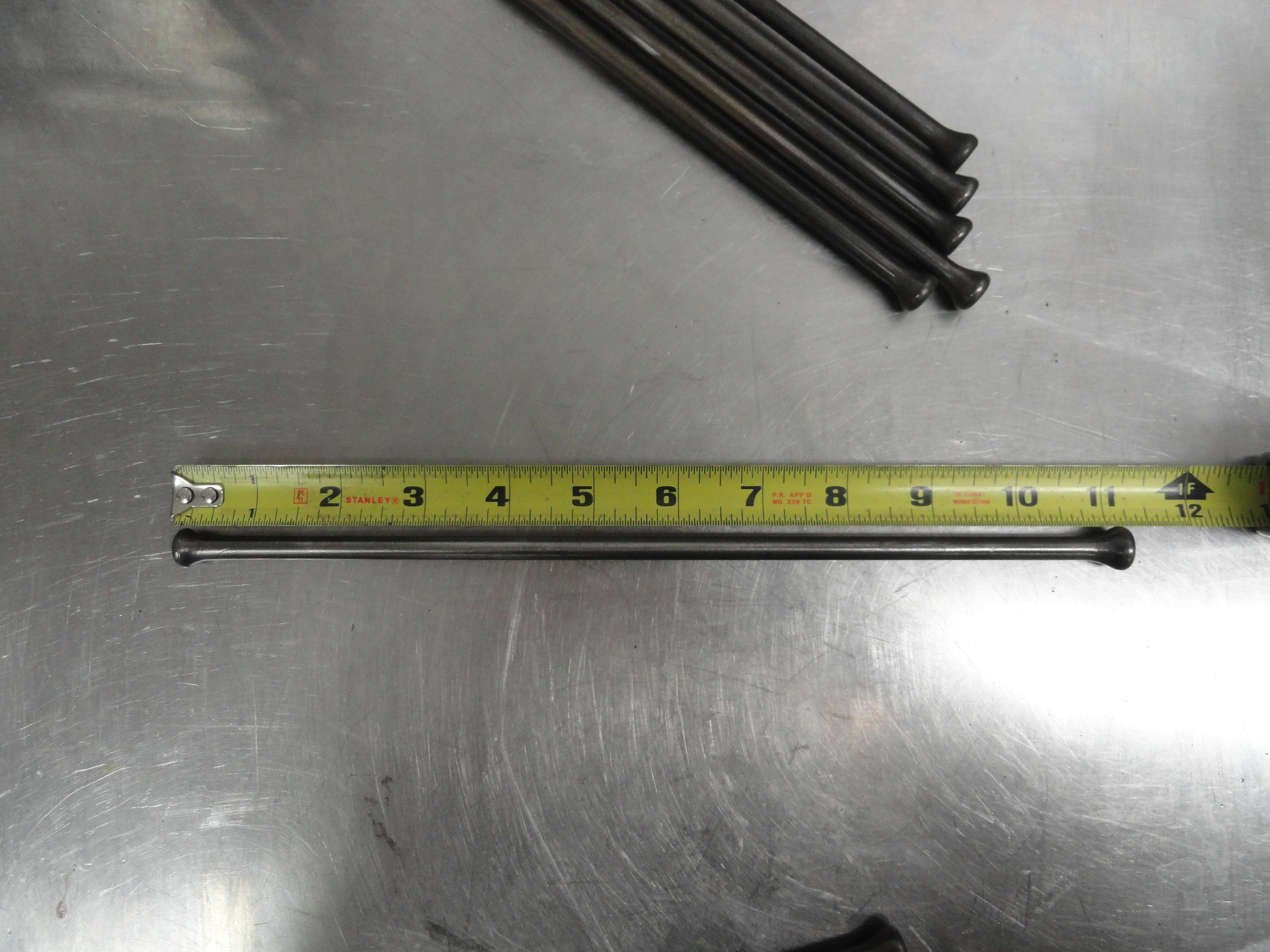
This engine has 11-1/4" Push Rods.
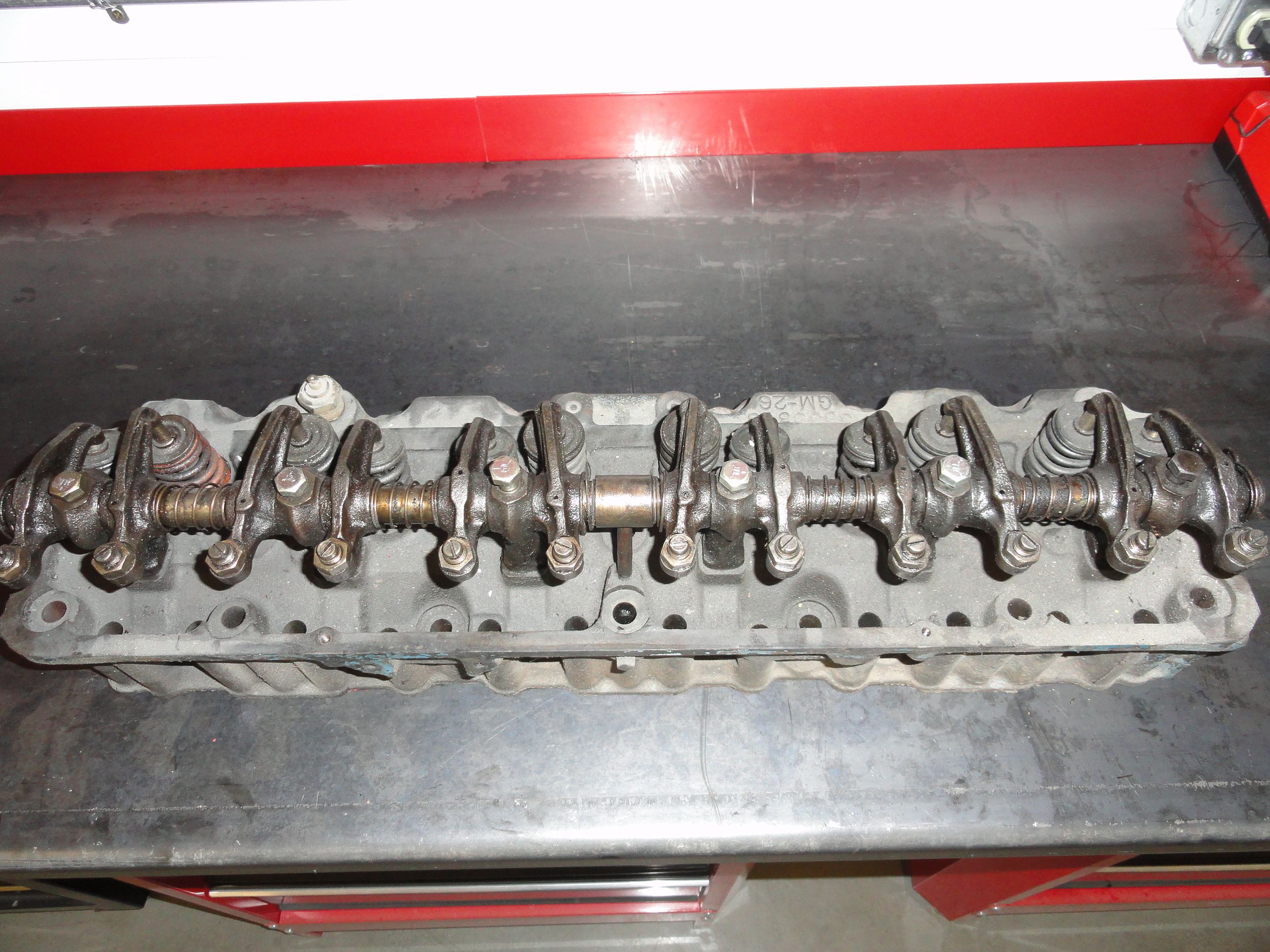
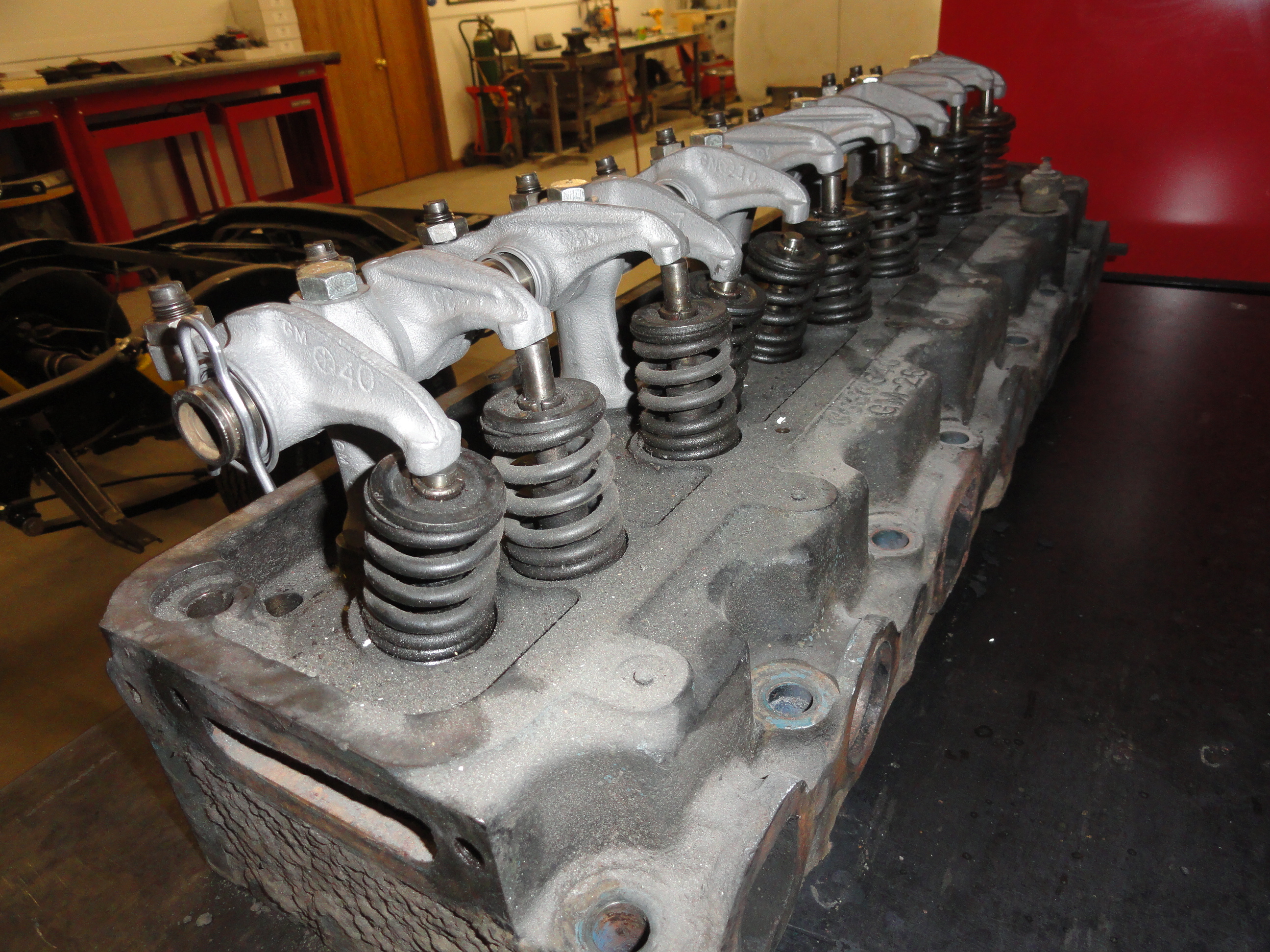
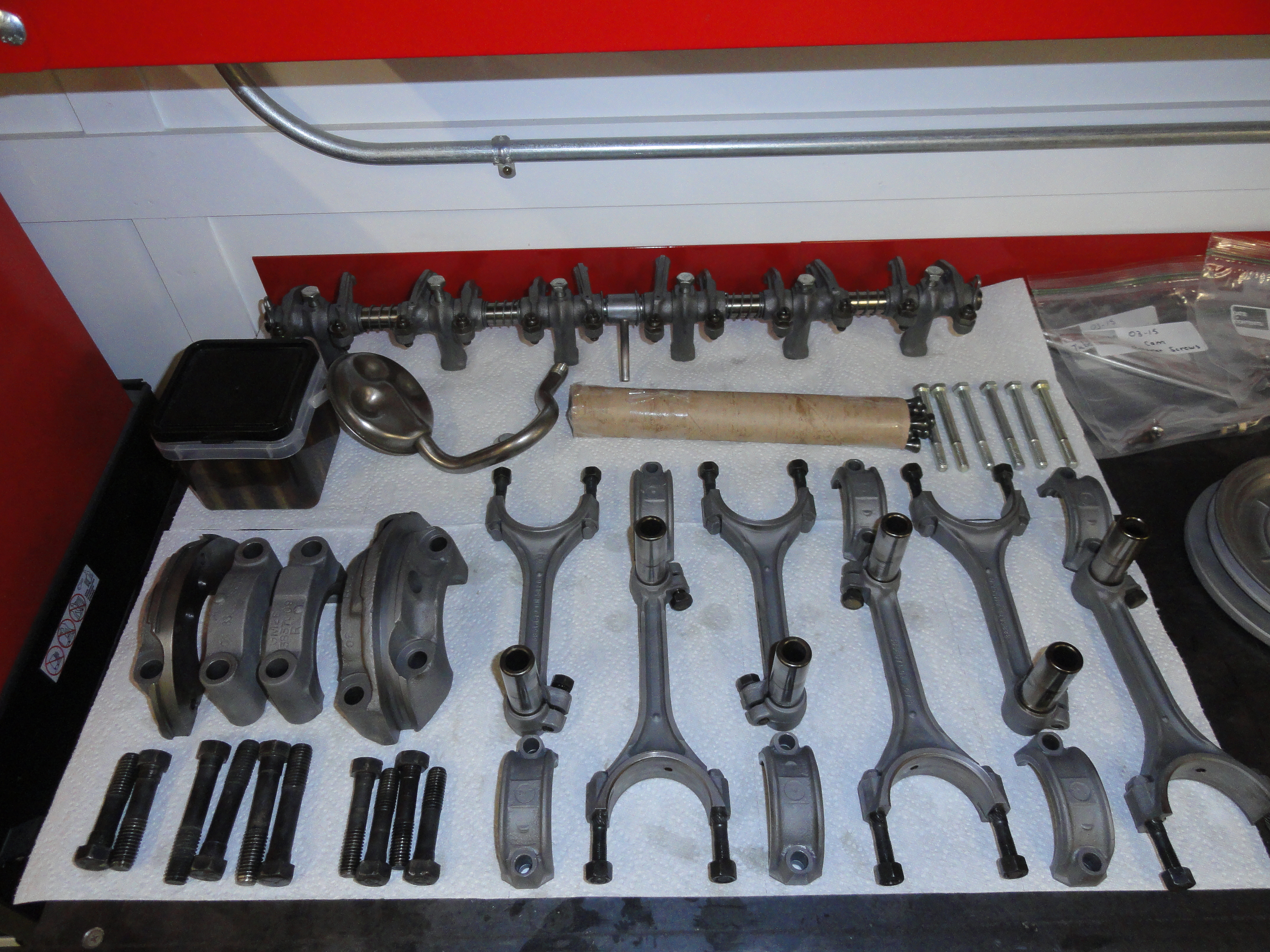
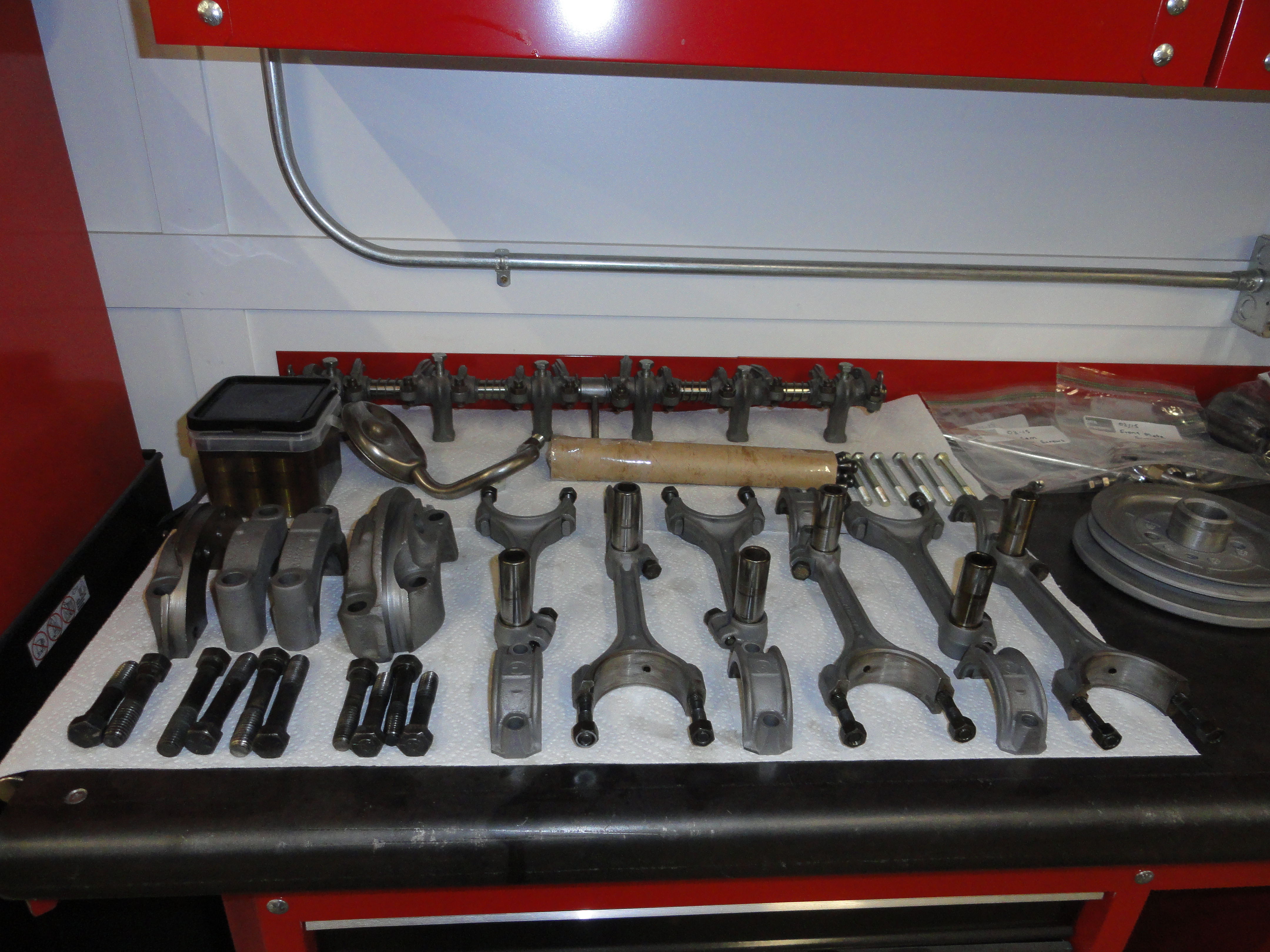
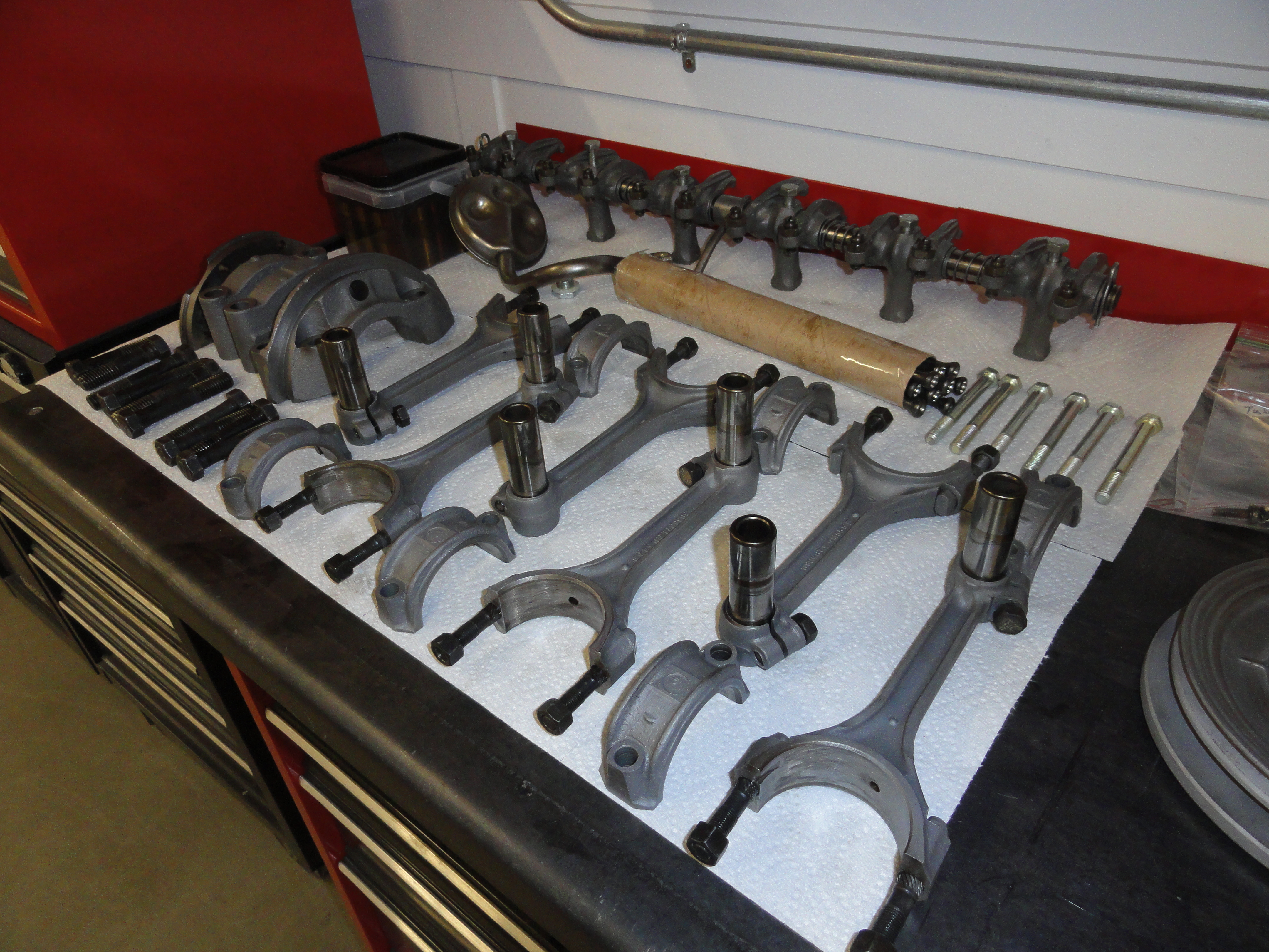
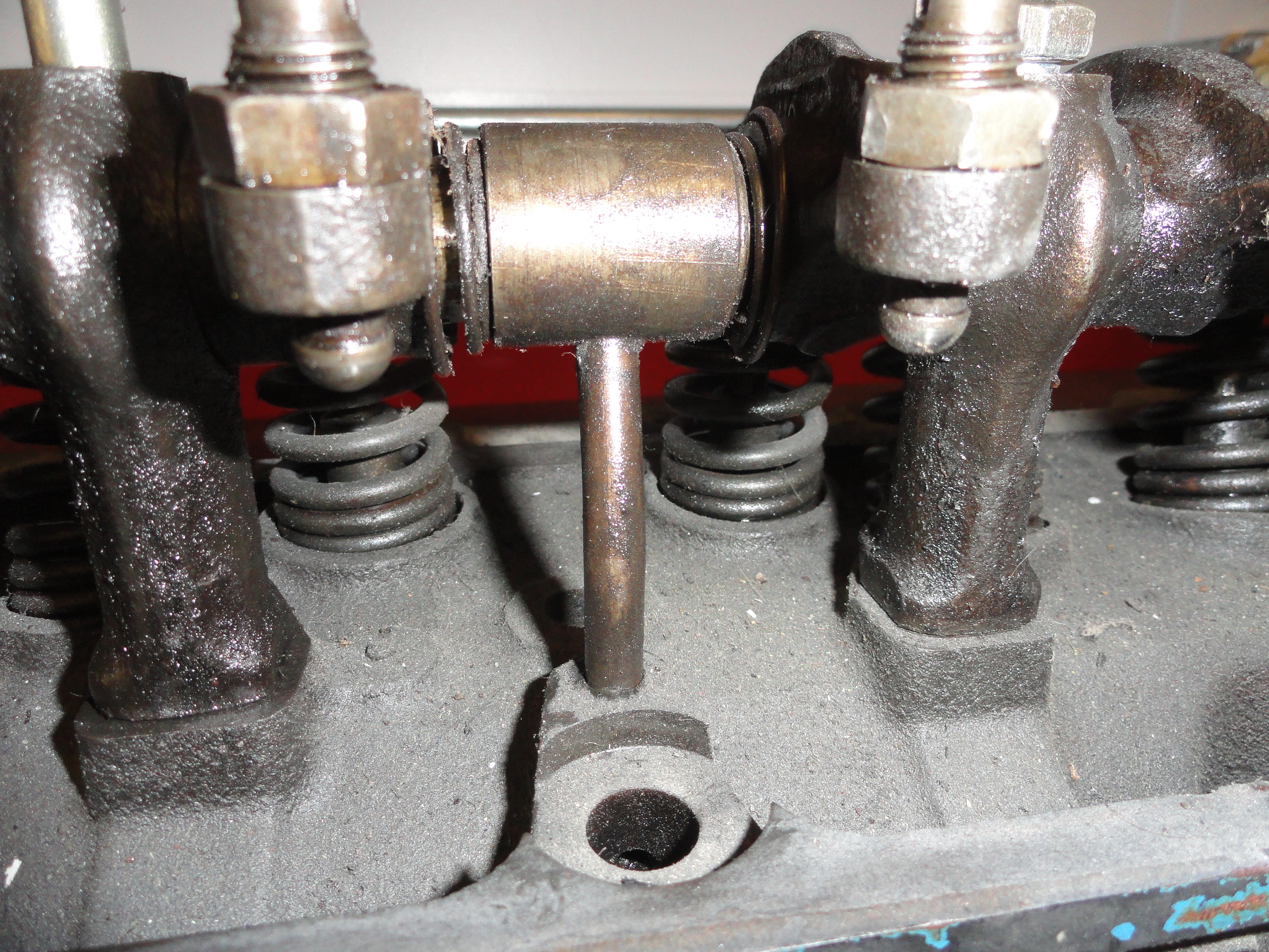
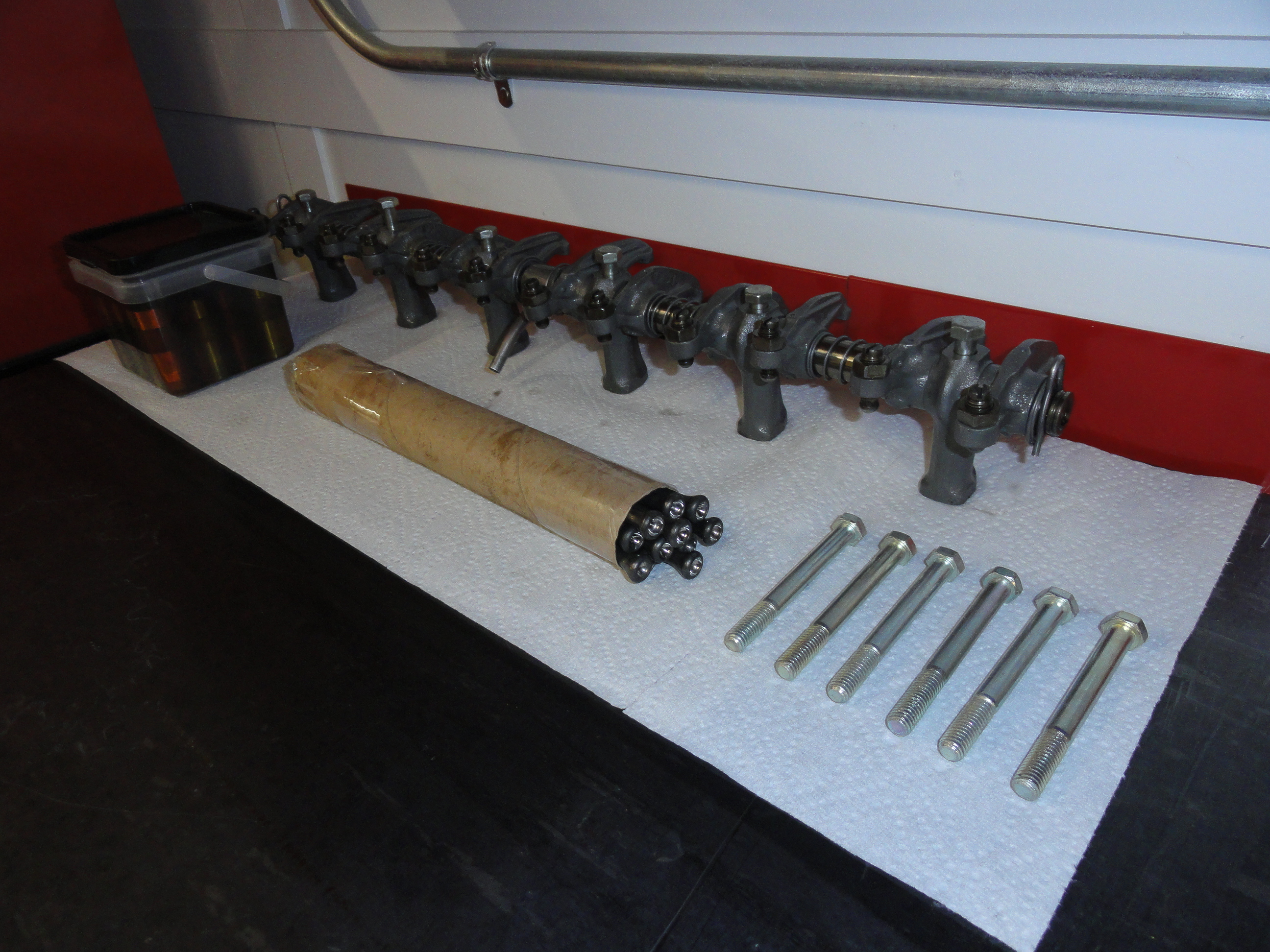
Now I haven't taken any of this project to my engine/machine shop yet, but there are many things we can do beforehand. The Rocker Assembly is one of them. This assembly is bolted on top of the Head and consists of two shafts, the rockers, springs, etc, etc. This is the assembly you adjust your Valves with. It goes together only ONE correct way. Getting any shim, or spring in the wrong place will lead to excessive wear or premature failure. This assembly is notorious for being very dirty, mostly or completely clogged, and the mounts can be stuck to the rocker shaft. Just doing this right will make this engine so much better. With all of these parts just sitting in a box, I reconstructed the assembly just to make sure we had all the parts and everything was serviceable. Then I took the picture on the left so I wouldn't wonder how to put it back together. Lucky for me I have a 261 sitting in the shop and I took the valve cover off just to make sure. This engine is the newer style 235 with a center flow spout that has no second tube coming out and looping back to the bottom of the assembly. This newer style puts all of the upper engine oil flow through the rocker assembly shaft system before dumping it back into the reservoir.
As with everything else, I like to clean things very thoroughly before even thinking about a successful assembly. Too often, cleaning reveals something you need to address. In this case, I will go out of my way to ensure this assembly is perfectly clean. To do this, you really want to take it apart carefully and place things in the proper order. In this case, there are two rocker shafts that meet in the middle. Once disassembled, these two shafts need to be inspected carefully for excessive wear. It's very common for these rocker shafts to be considerably worn where the rockers move on them. It's worse when there is no oil reaching the rockers. In the case of this engine, both shafts have very little wear and look really good for their age. Now take about a 14" piece of 3/8" steel rod and push it all the way through the inside of the shaft. Do it very slowly and knock off all of the crud with a small screwdriver or something as you go past each hole. Use your parts washers pump action to push Kerosene through the shaft. Repeat doing this until all that comes out is clean. On the outside, use double O steel wool and make sure the entire surface is perfectly smooth. Don't expect to get all the stains off, but do clean it thoroughly. Don't use an aggressive grinding wire wheel for this. The finish needs to remain as much as possible. Do NOT sandblast the shaft.
It's always a good idea to pick up a Shop Manual for your particular engine. Since the Shop Manual for a Truck of that year is
very similar to the Car Manual, I use what I have. Remember, this is a Car engine. Of course the only difference is Hydraulic
Lifters and Cam. There is a nice picture of the Rocker Assembly layout in the manual. The Manual will have most of the information
you need to really do this right. When in doubt and even when you think you know, check the Shop Manual. It will keep you out of
trouble!
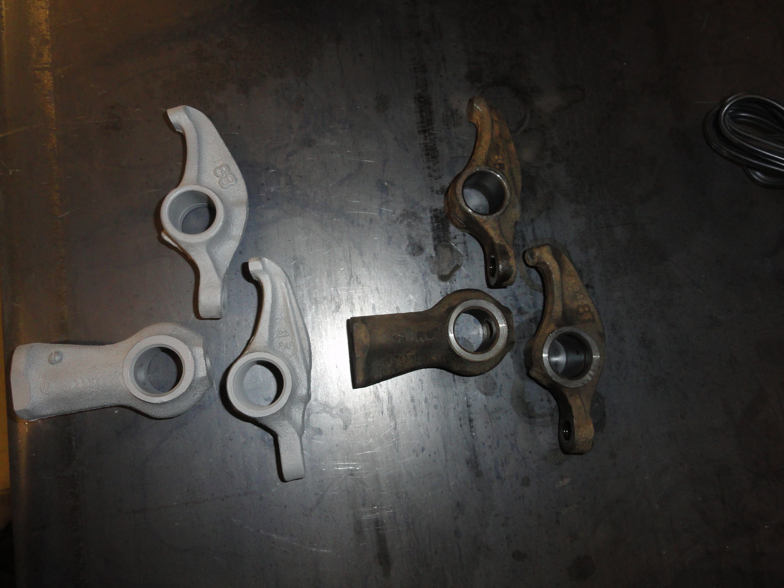
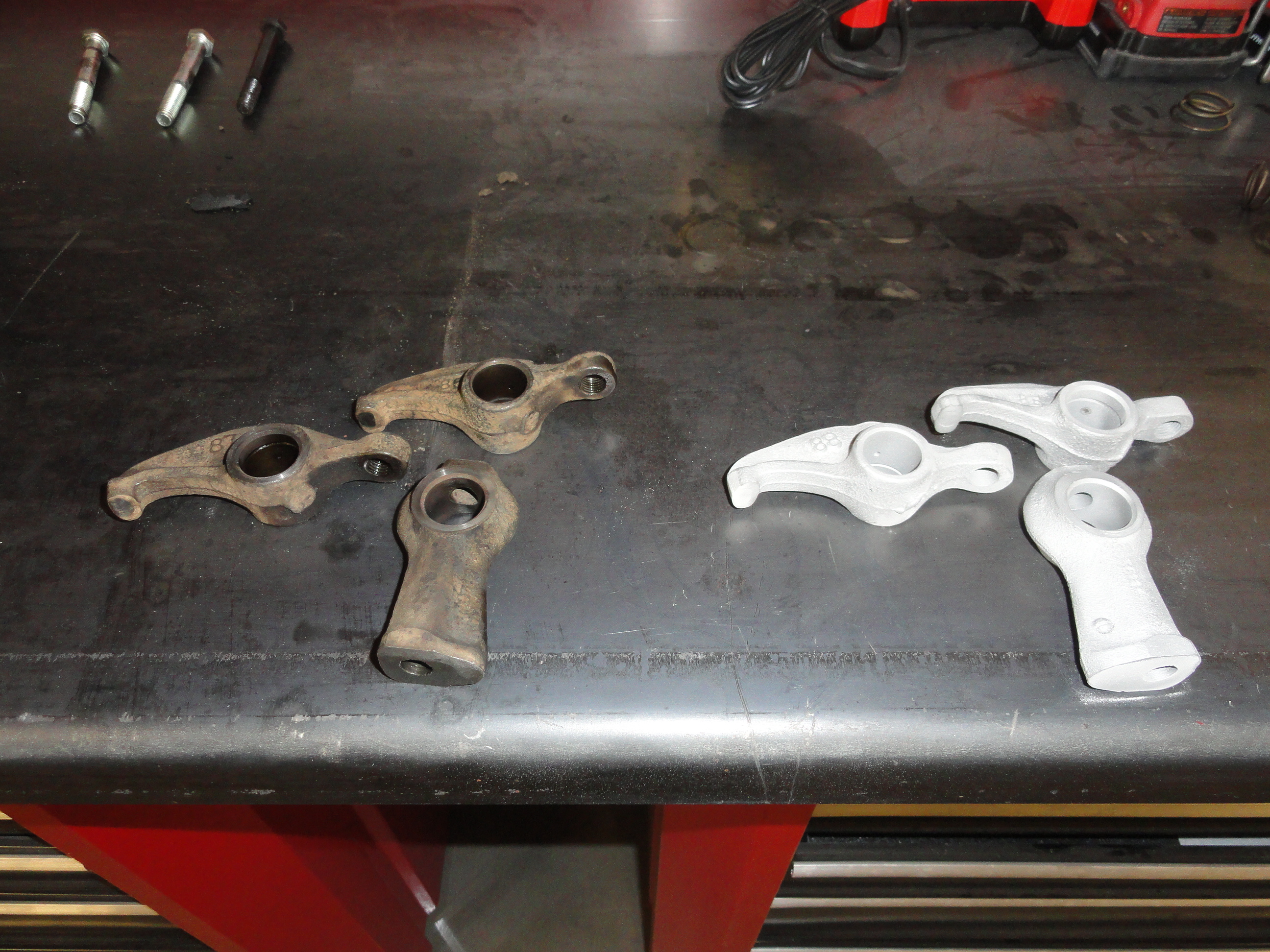
At this point we need to clean up all the Rocker Assembly parts. I first run them through the Kerosene wash, dry them off, then remove the push rod contact assembly from the rocker arms. This is because we want to thoroughly inspect the ball that comes in contact with the push rods to ensure there is no damage or excessive wear. We also do not want to sandblast that part of the rocker. Once apart, sandblast the rockers but do not hit the valve contact area. I just avoid that but if you want to tape that small area up, that works too. I use my blast cabinet and #1 Silica Sand to do the job. It's almost the consistency of Flour or Fine Sugar so it is very gentle on the parts. The truth is, it's just to make them look better than new. If you don't have a blast cabinet, a good cleaning with Kerosene then light oil would work just fine.
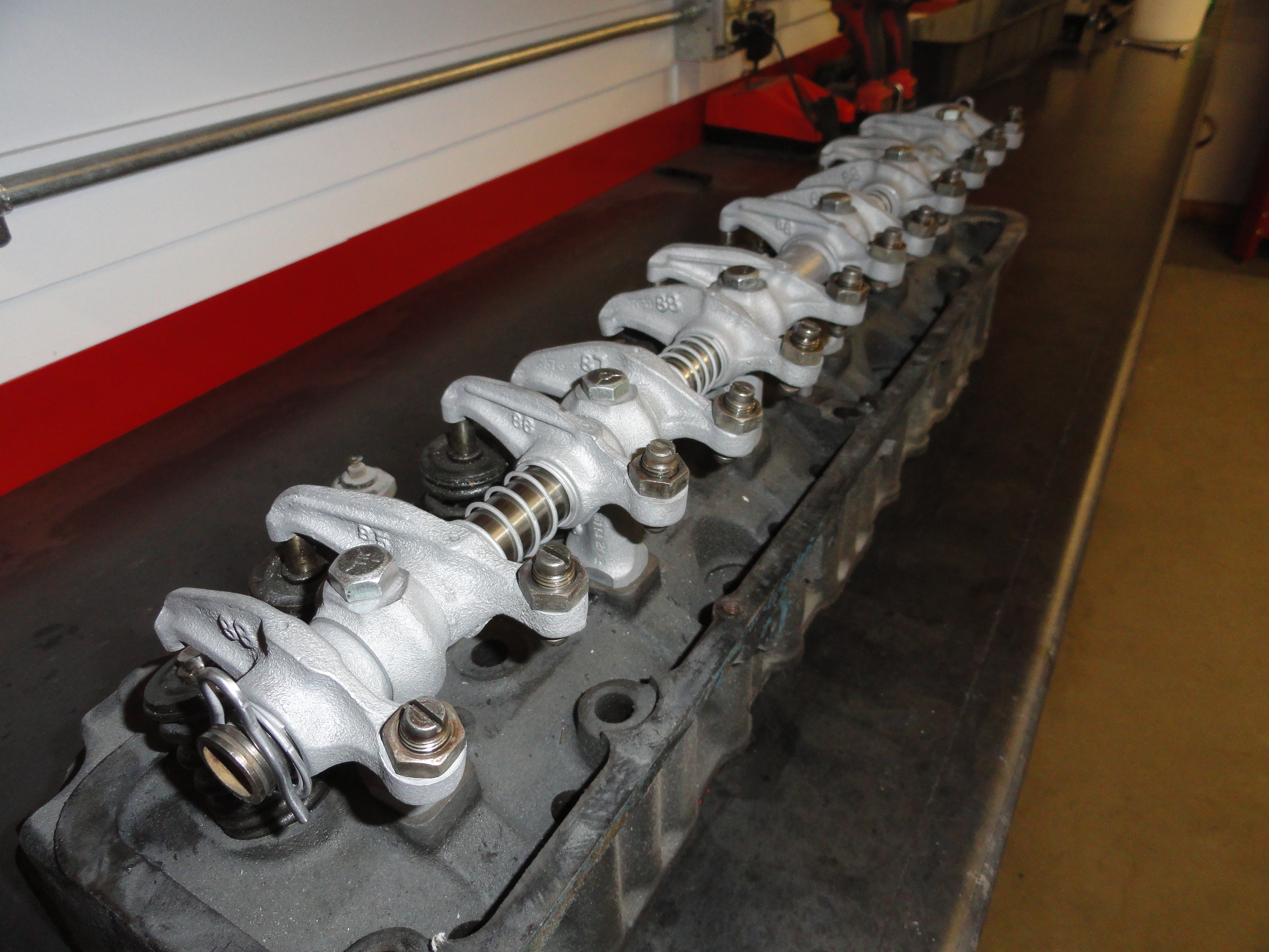
You want to clean each Rocker thoroughly. Chase the threads, use a piece of safety wire or a paper clip to clean that little oil hole then once blasted or otherwise, take some 400 grit sandpaper and run it through the shaft hole, on the flats of everything, then remember when assembling the shafts oil holes face downward. Once the entire assembly has been cleaned, put it back on the Head to make sure each Rocker contacts the Valves exactly in the middle. Once you are happy with the whole thing, spray some WD-40 all over the assembly just to keep the rust at bay while everything else is happening. I like to leave about 3 threads showing on the Rockers. This is a good neutral position for the Valve adjustment procedure later on. Once your Rocker Assembly is all nice and clean, set it aside. As this rebuild progresses, you will be glad you addressed these issues before going to the Engine Machine Shop. Had any lifters or rods been bad or you want a second opinion, you will have this information beforehand. Now the Head is ready to go and get its machine work done. Let's take a look at the engine next...
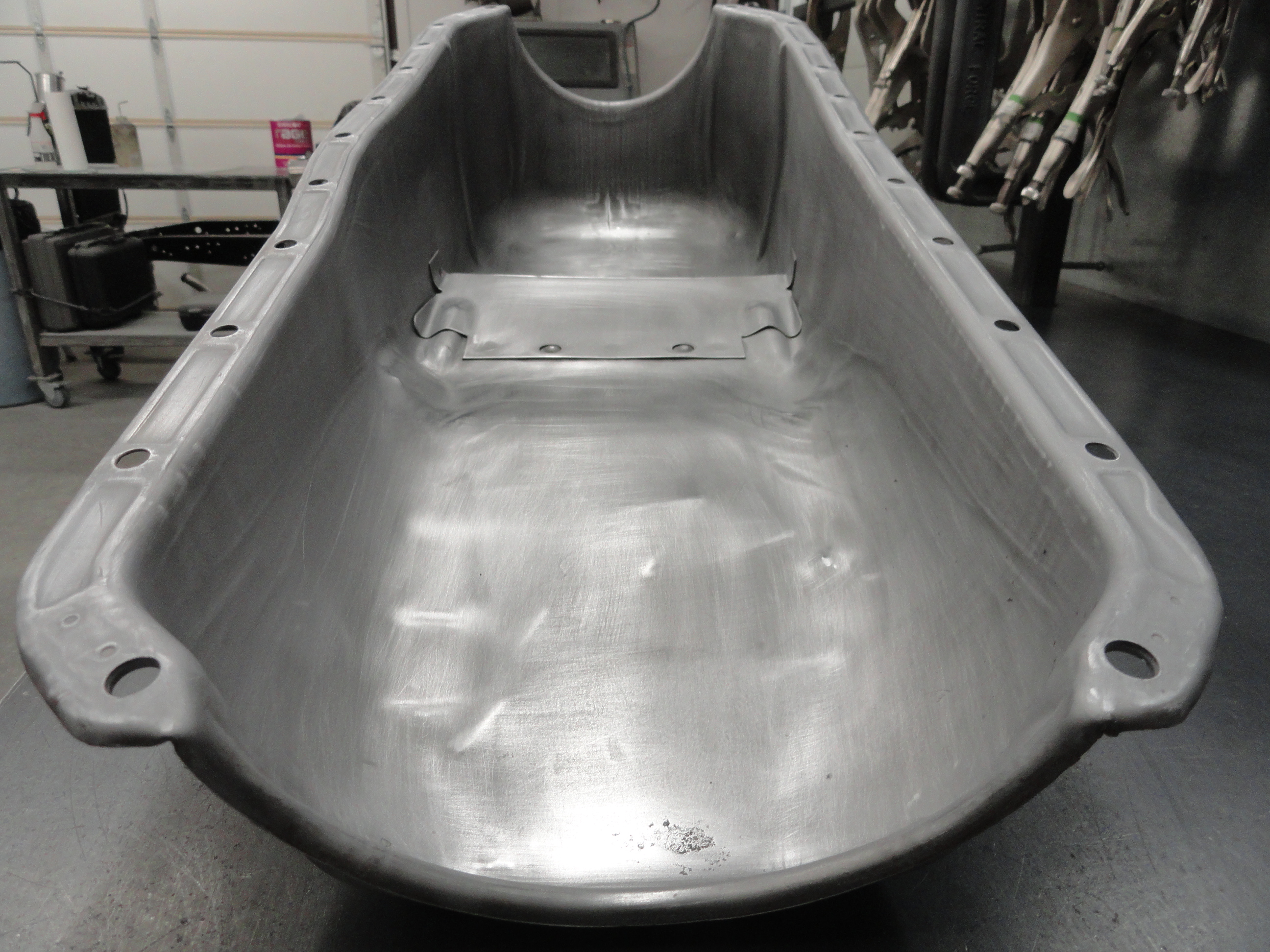
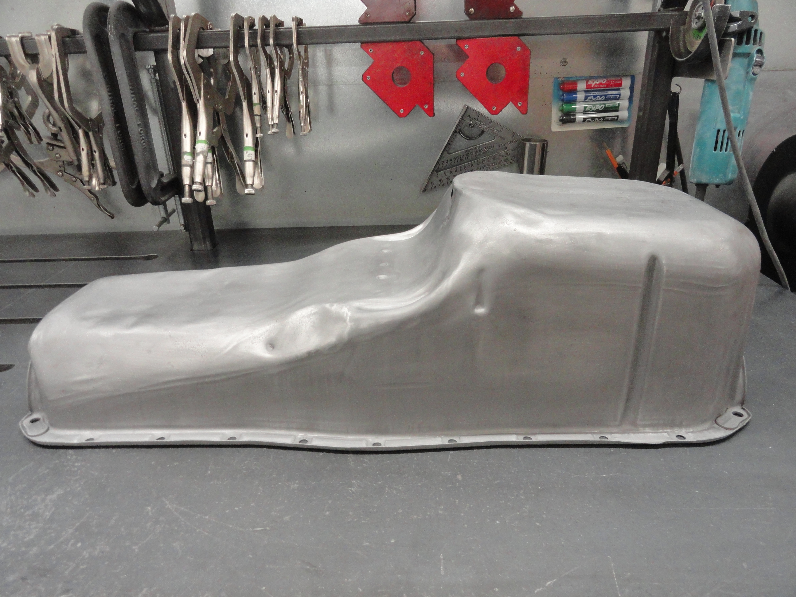
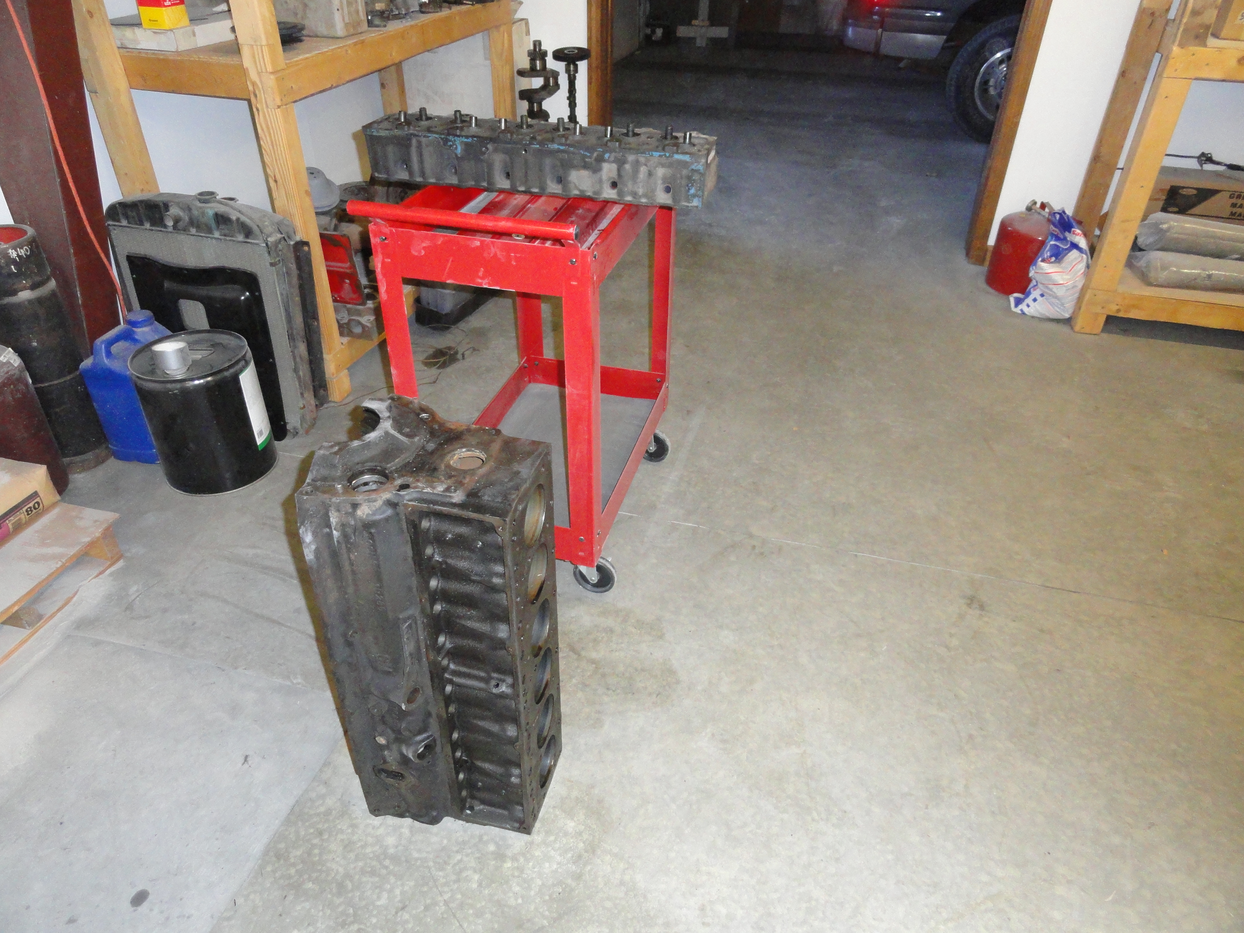
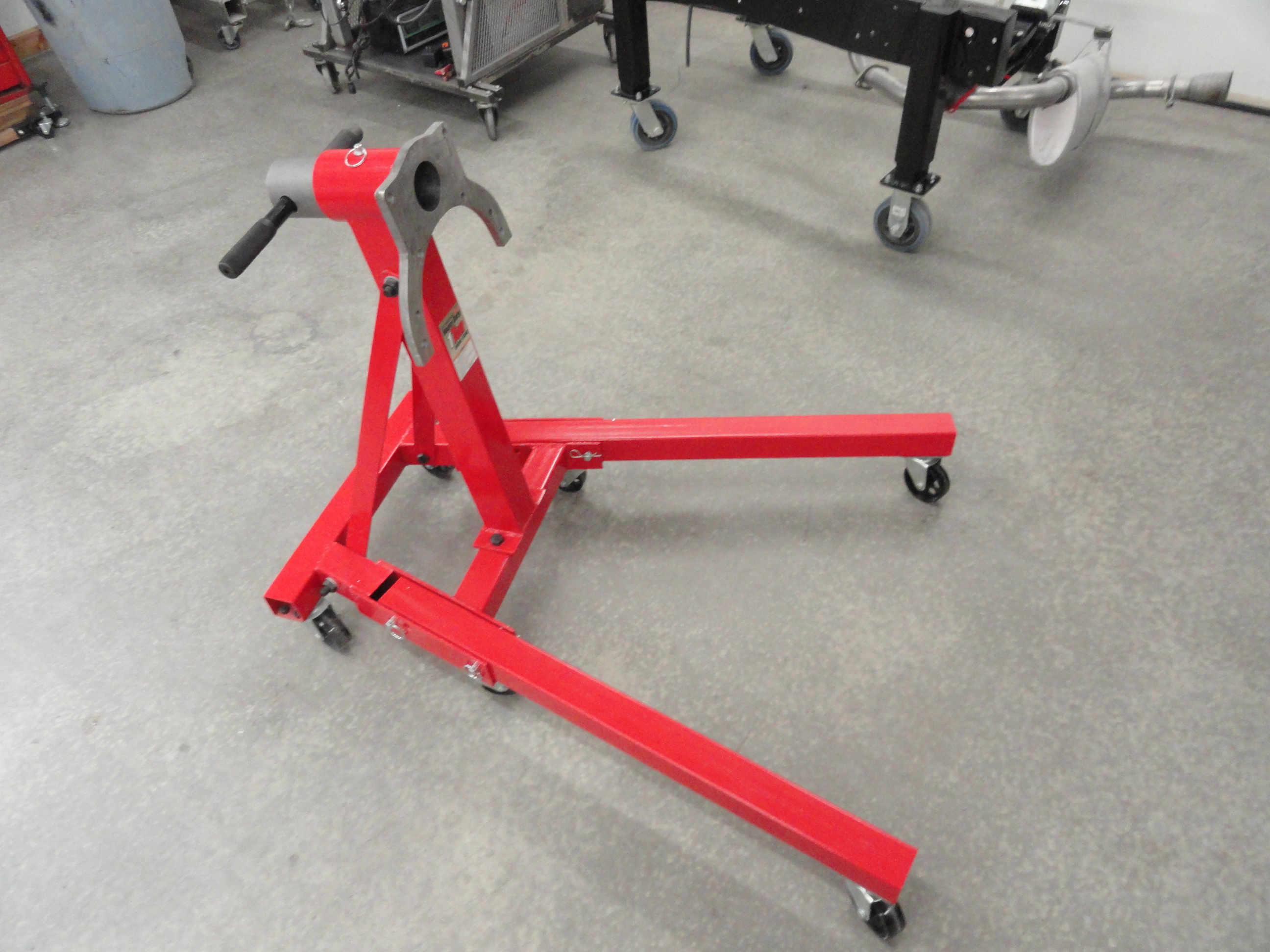
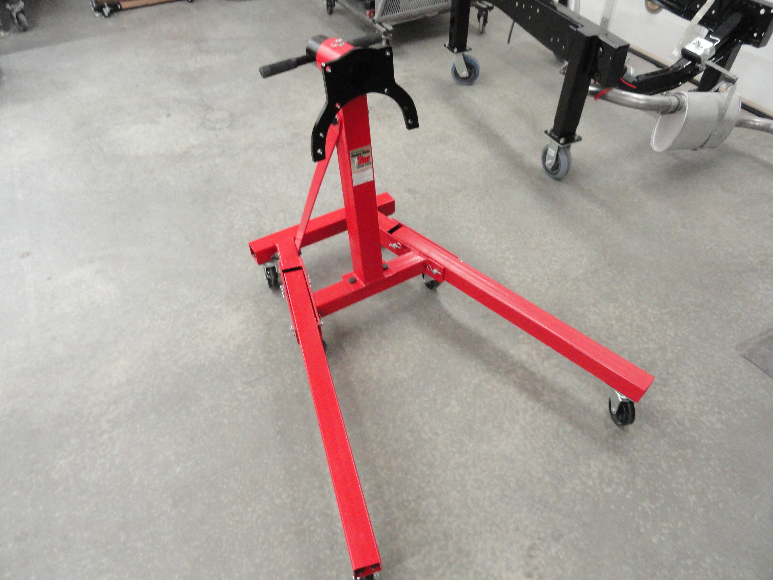
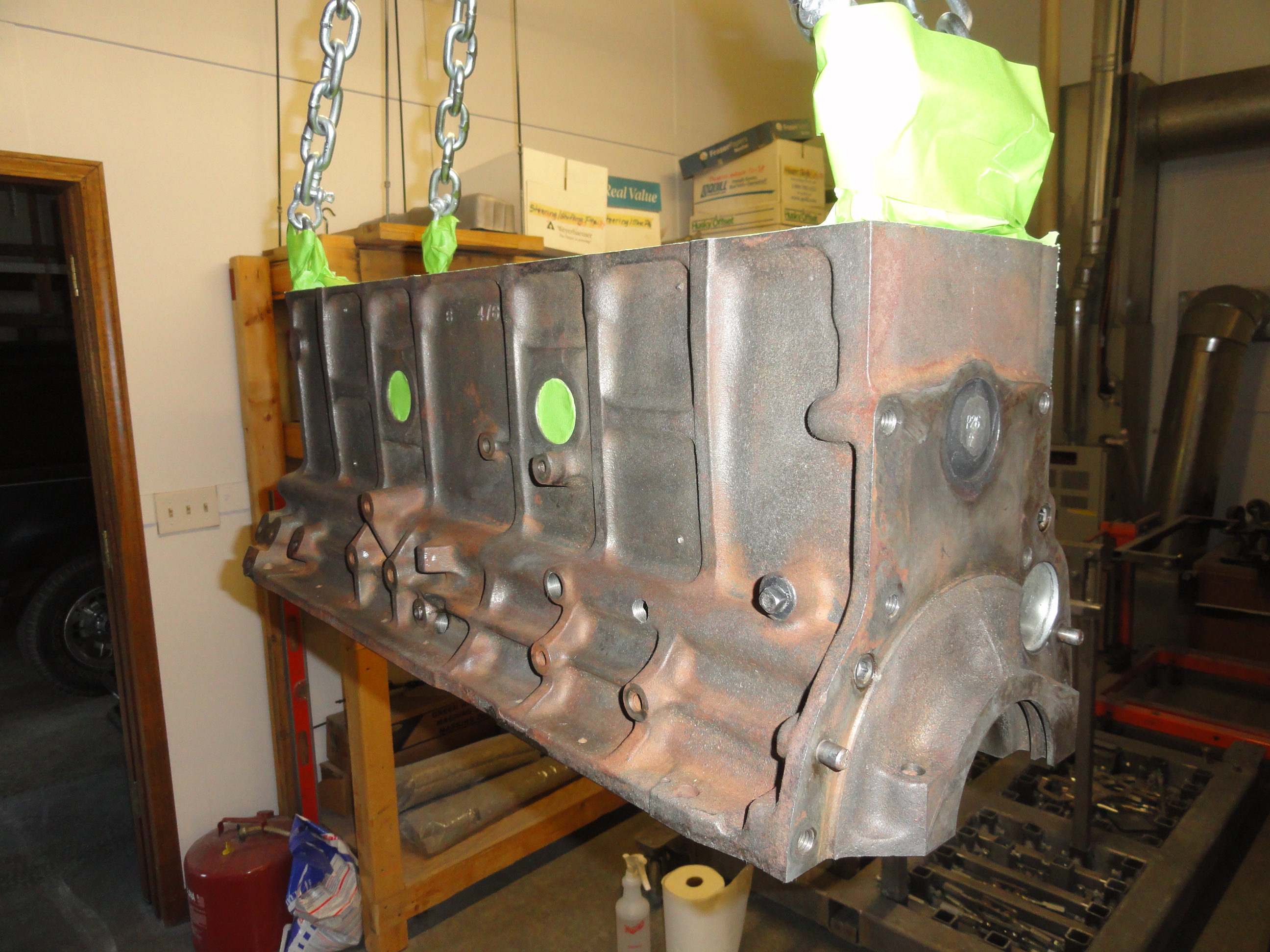
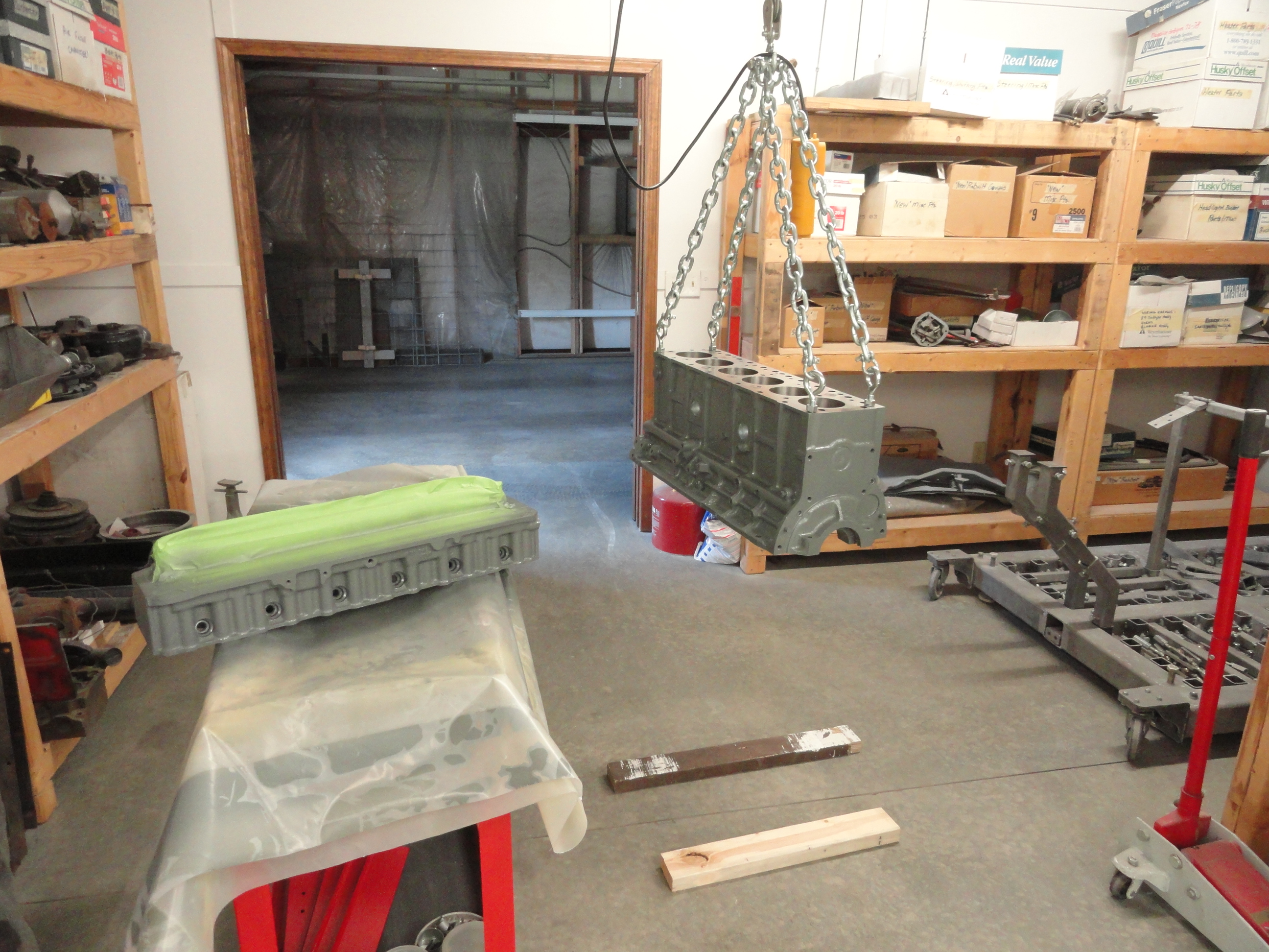
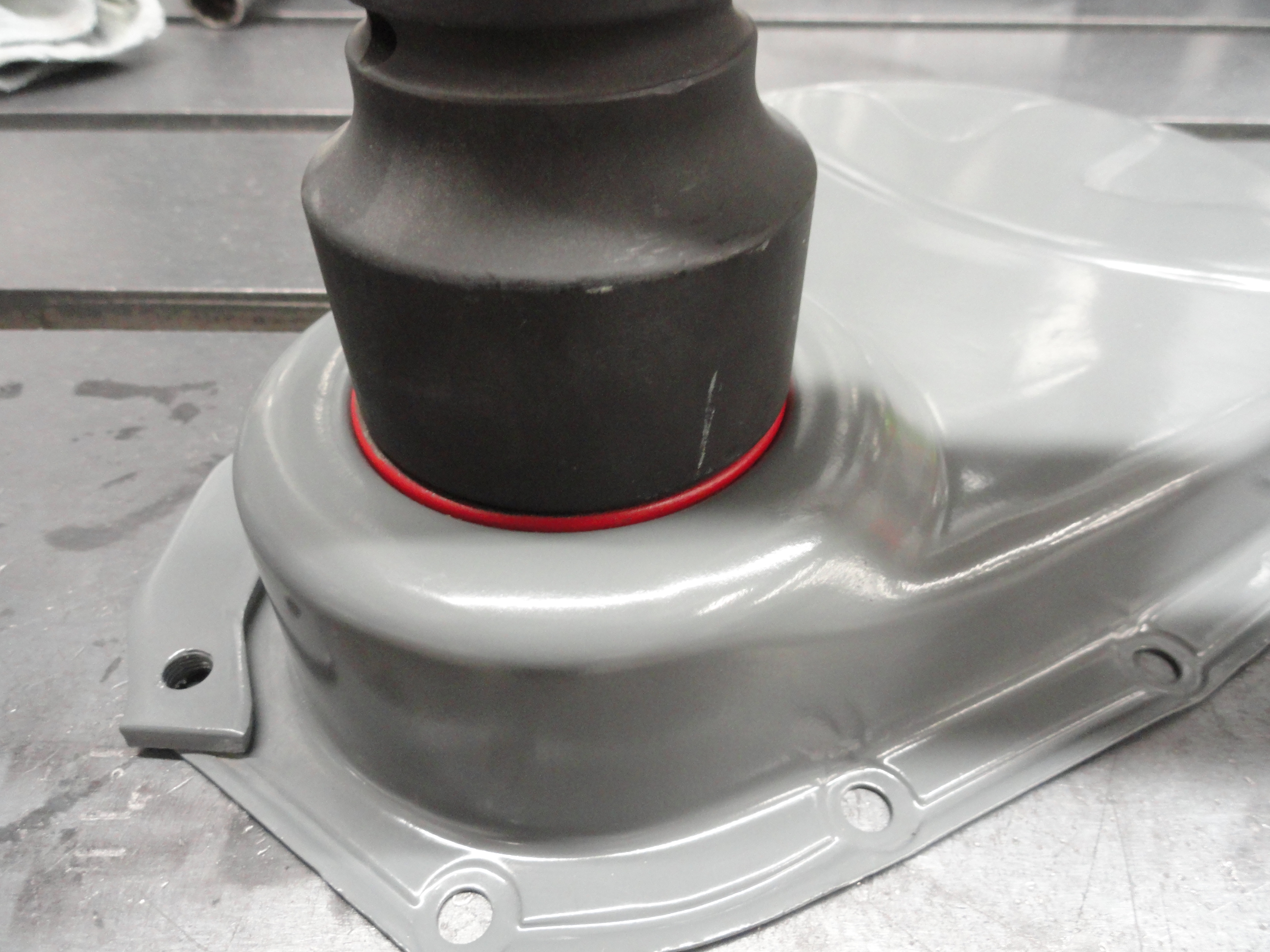
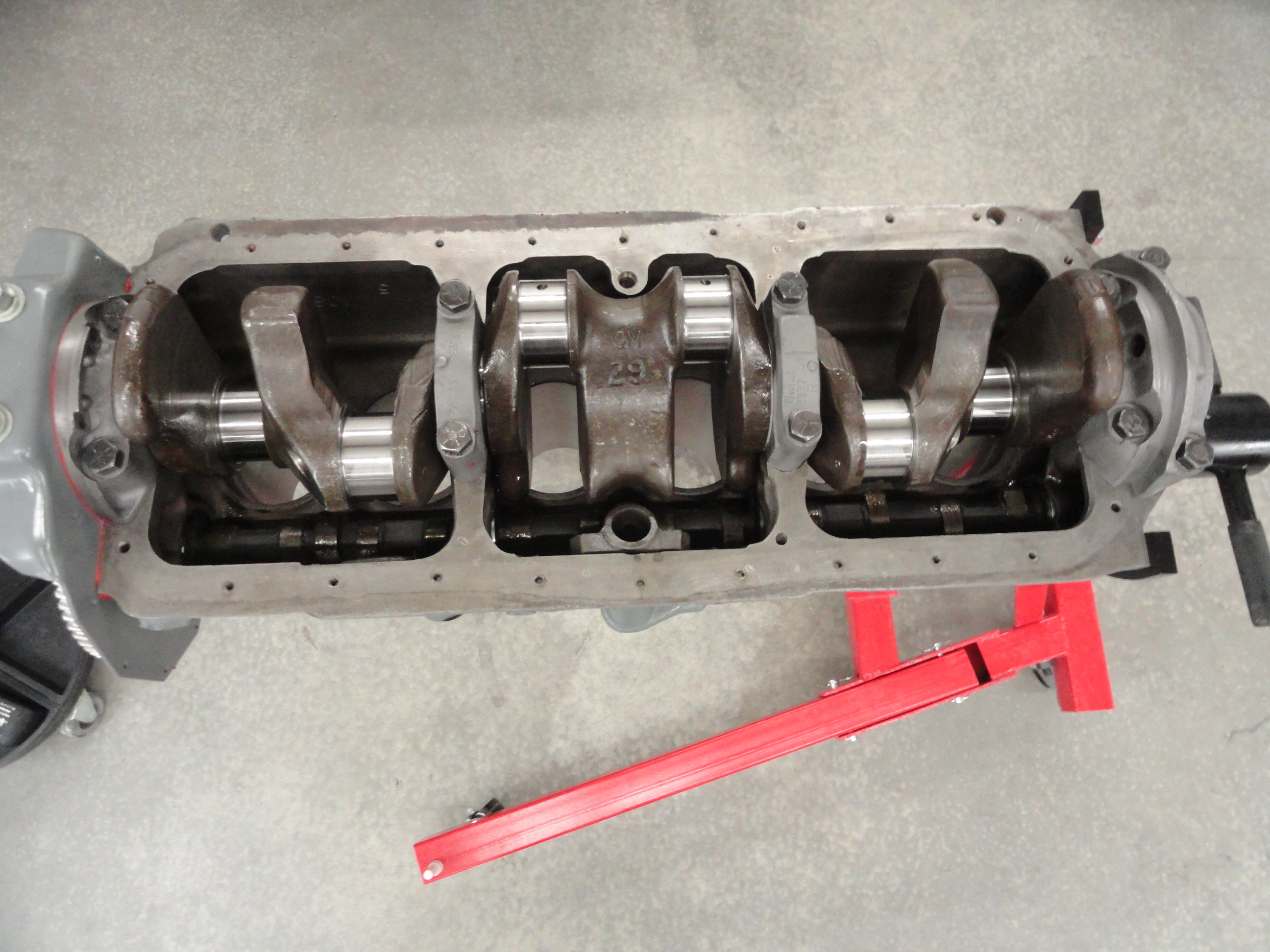
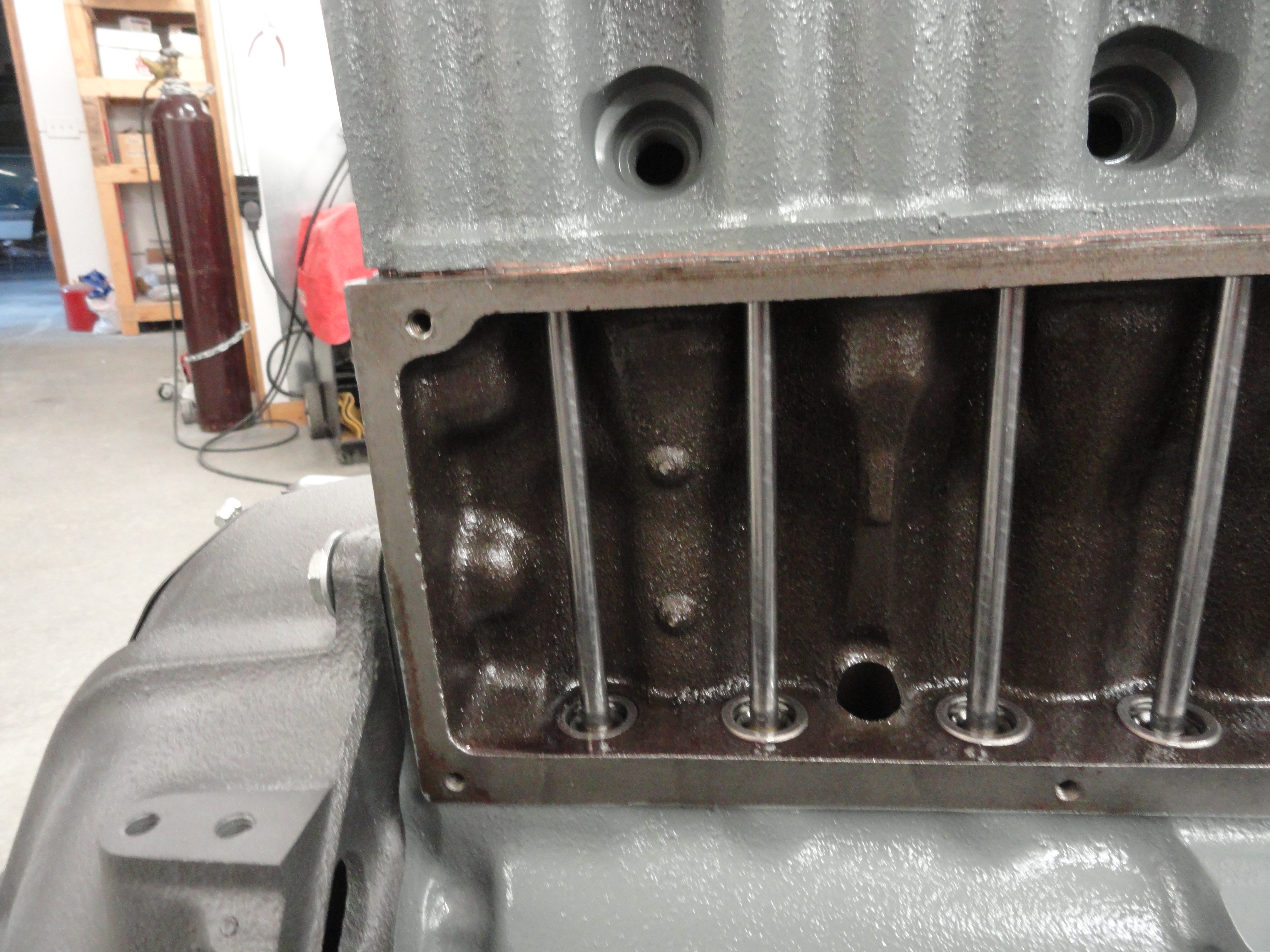
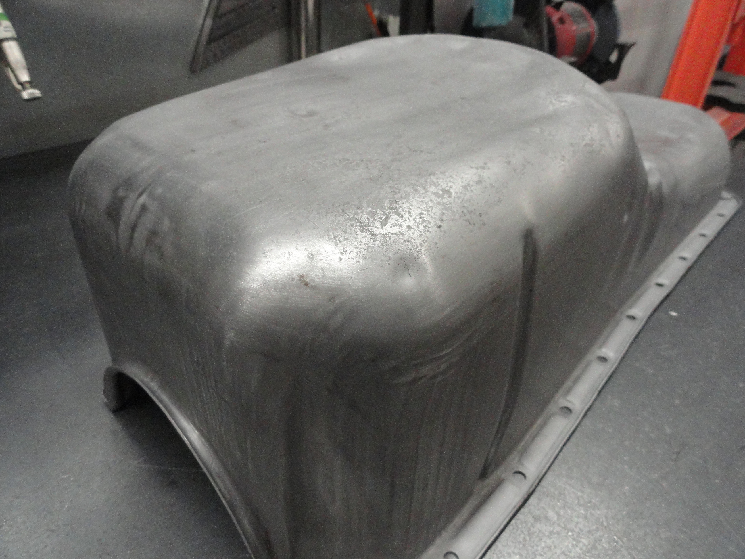
This particular engine was given to me sitting on a pallet, oil pan UP. I transferred it over to one of my wheel dollies so I can move it around. This is a good orientation to start with. Once the Head is removed, you have a nice flat surface to set it down on. First order of business is to remove the Oil Pan. It should be bolted down with exactly 18 screws and 4 Hex Head Bolts. Once you have that many screws in your hands, take a rather thick tool, something like a 1-1/2" stout Scraper to try and pry it off the Block. I don't like Screwdrivers for this because of unnecessary pry marks on the Pan. Use the same Scraper to scrape all of the gasket material and crud off the block. Once the Oil Pan is off you can see the condition of the inside.

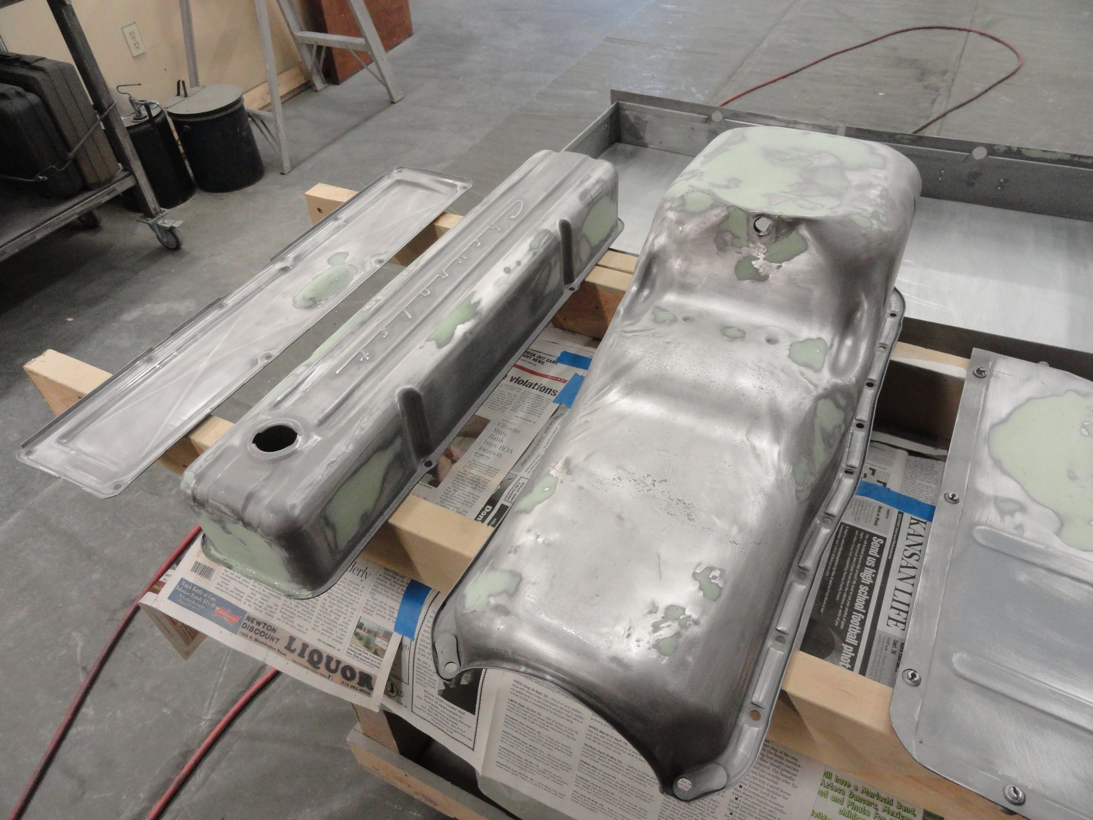
The Oil Pan is probably the most neglected piece of tin on the truck. Rocks dent it, the stress warps it, and then a gorilla comes along and over-torques the drain plug. Then, water condensation causes major rust pits and even rust-through. I spent an entire day sandblasting this Oil Pan and inspecting it. Once it's sandblasted, I took 400 grit sandpaper and sanded the entire pan inside and out. This makes it easy to see cracks, bumps, abnormalities in the surface.

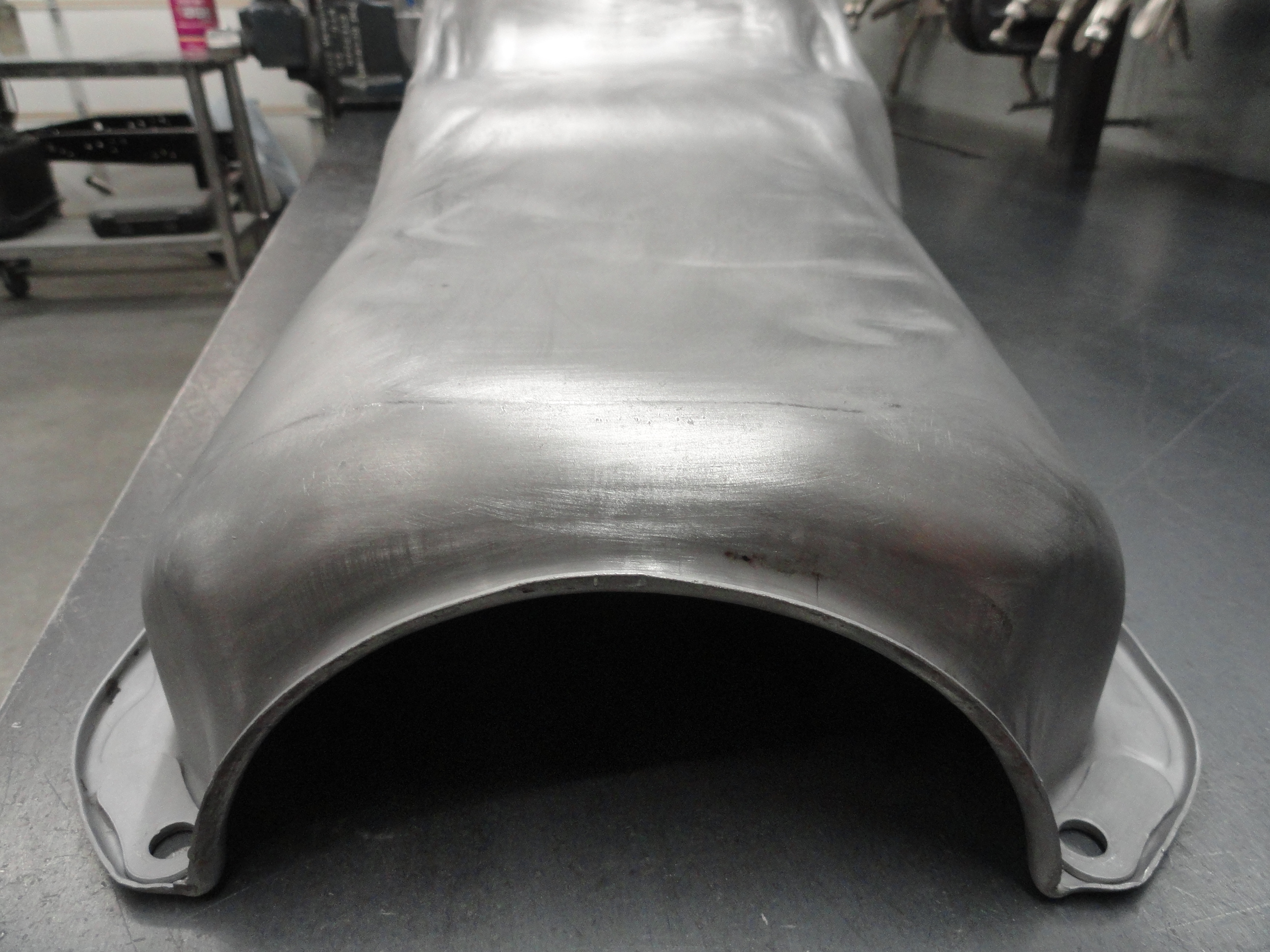
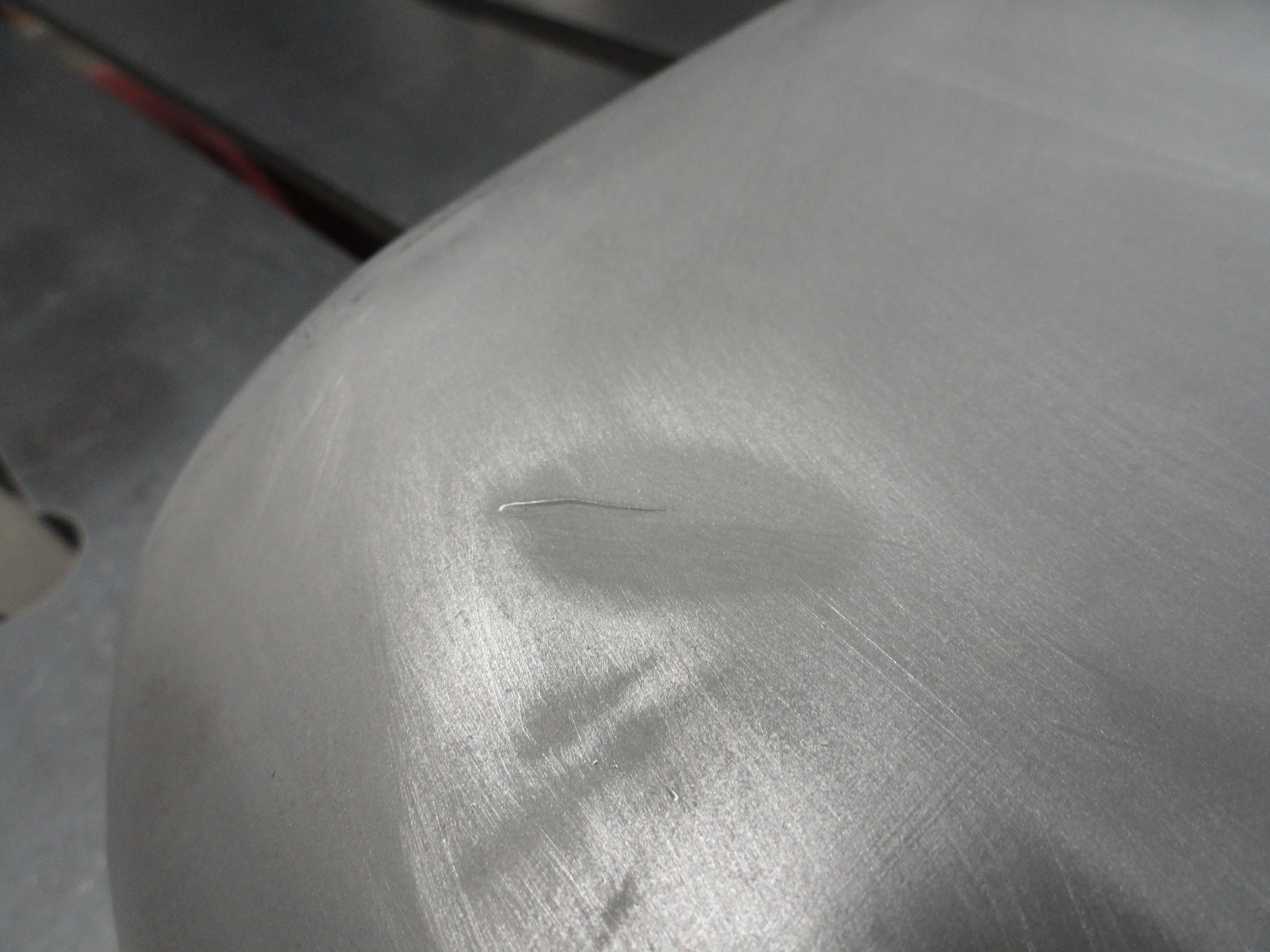
In this case, someone didn't want to address the small hole made by a sharp rock and used bondo to cover it. In all, I found 3 holes. One was a rock, another was rust through, and another was an actual crack, about an inch long. Nothing of any surprise really since the pan IS over 50. So, since it's down to the bare metal we can add some weld to seal these holes and cracks up. First a little body work, smoothing and light hammer and dolly work to get things straight again. Once all the bumps and bruises are smooth again, weld the holes and cracks shut, re-dress the metal, and then it's time for another decision.. how far do you want to go with dressing this oil pan up. There are rust pits and various imperfections. My answer is always NO SHORTCUTS!
If you follow up all of your metal working the same as if it were part of the truck, it gets rather time consuming. I draw the line with putting bondo on the oil pan because of rocks kicking up and making it look much worse than if you would have just used an Epoxy Primer. Even then, the least amount of substrate, the better. When welding up cracks, you want to start about 1/4" before the crack on each end. This ensures the unseen start and finish of it will be addressed too. The rust-through was minor and went pretty smoothly.
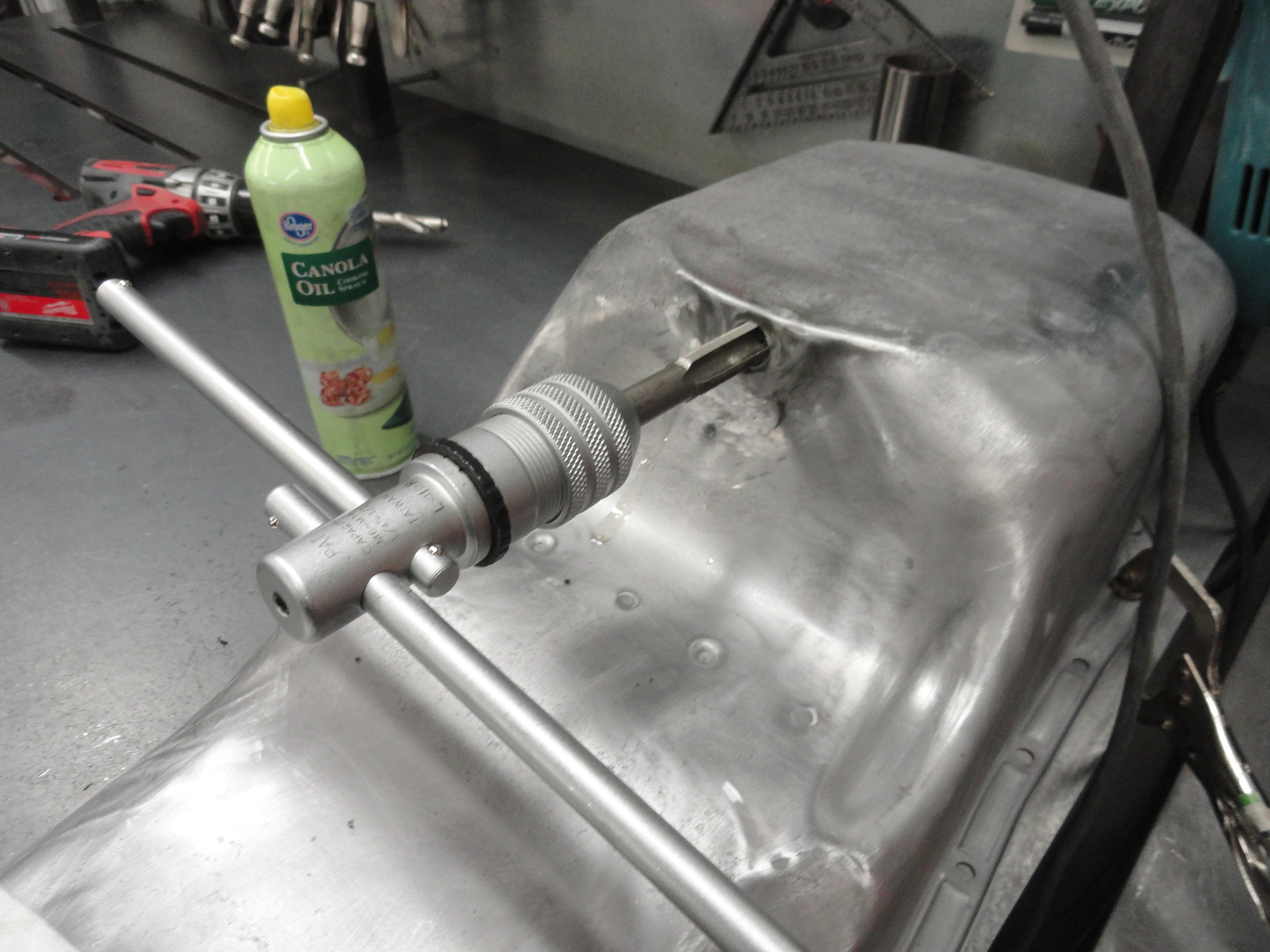
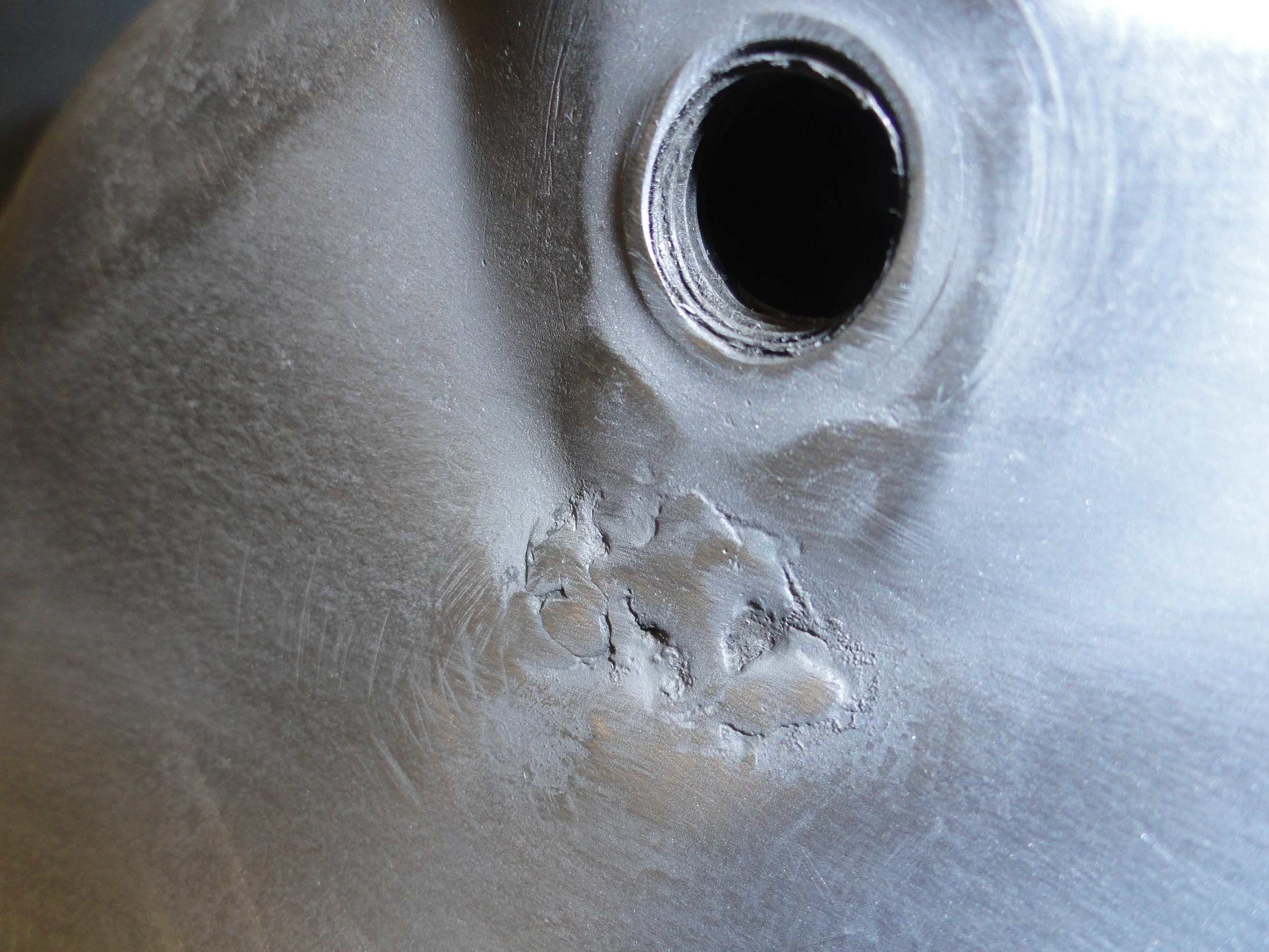
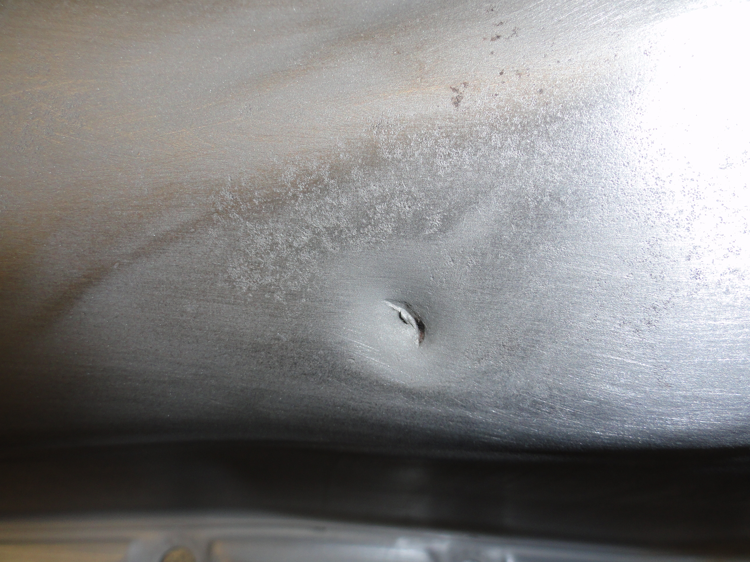
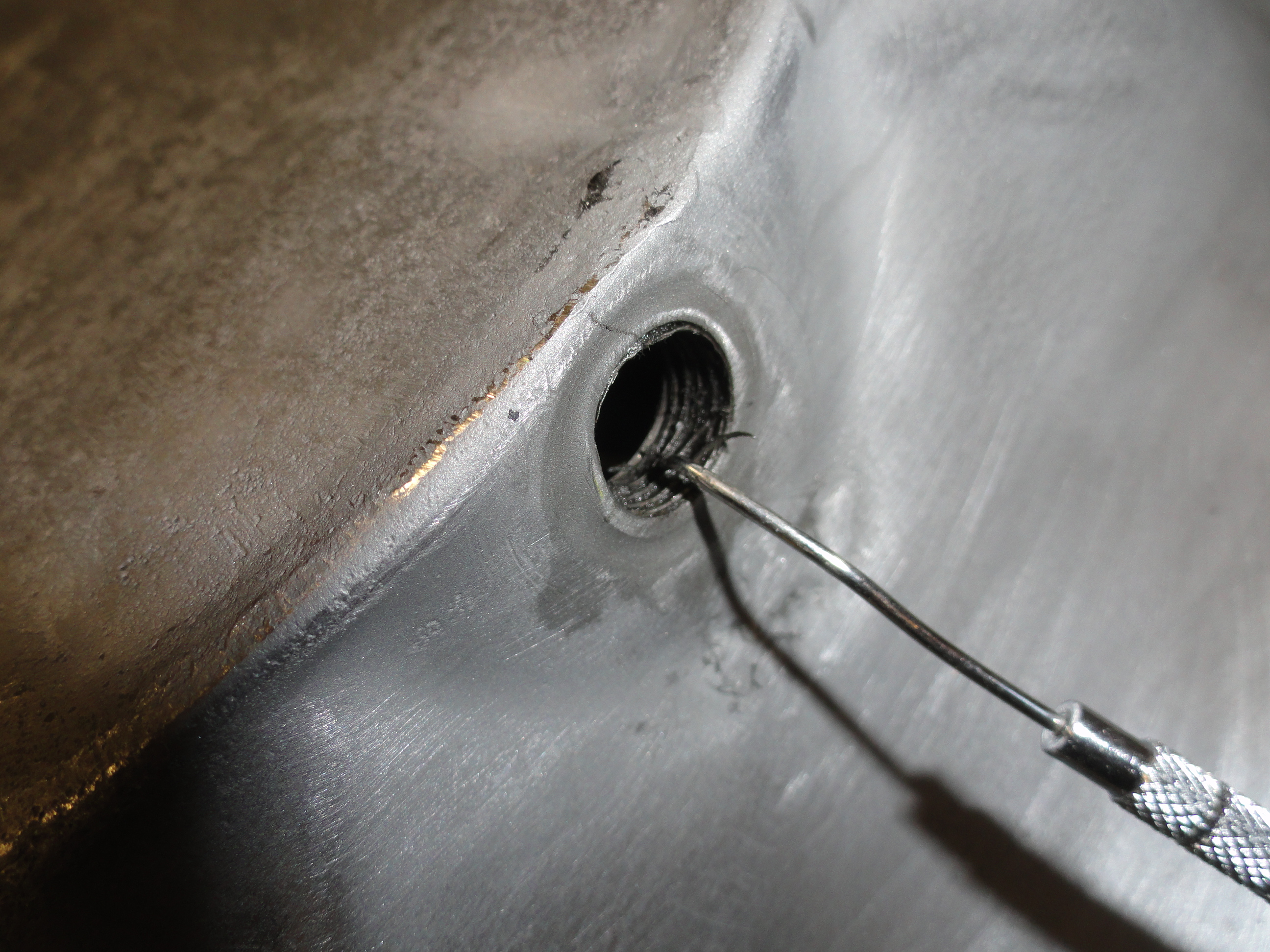
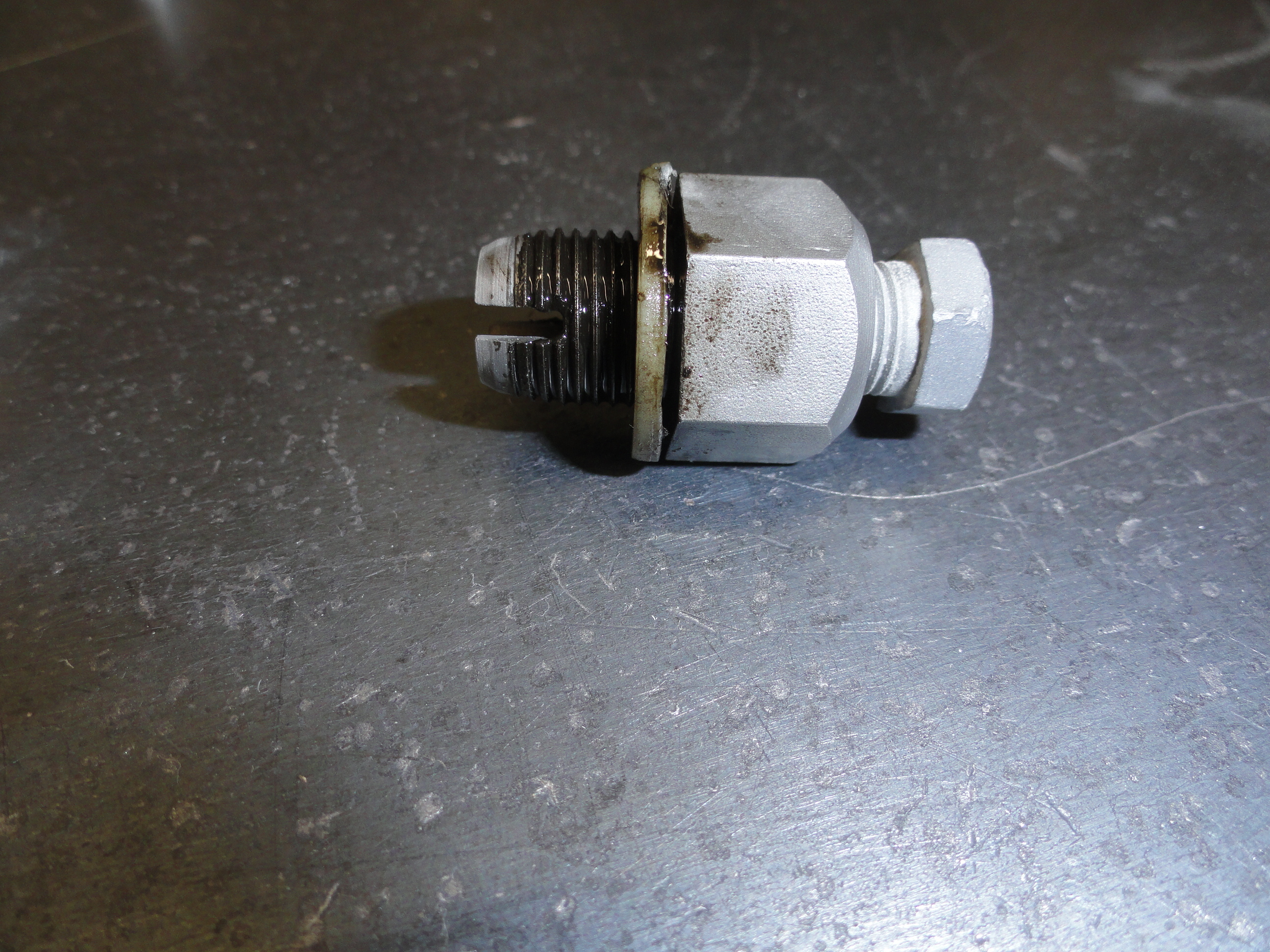
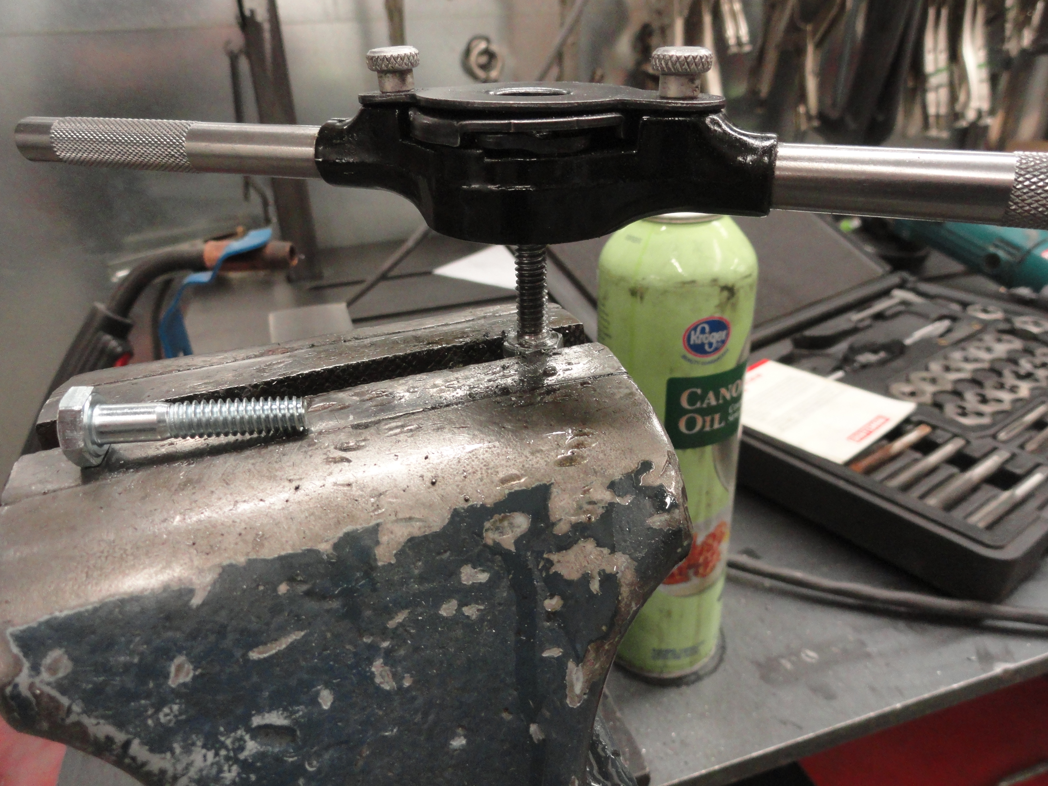
In this case, I had to address the stripped out Oil Drain Plug. Someone already put an oversize plug in, and it stripped out as well. After re-drilling the Oil Pans Drain Plug hole out to 37/64", Tap with a 5/8"x18 tap. Turns out this plug is available and a Dorman product (65313). It comes with the nylon gasket as well. This Oil Pan has a metal reinforcement at the Drain Plug that is plenty large enough to handle the size and then the pan is like new!
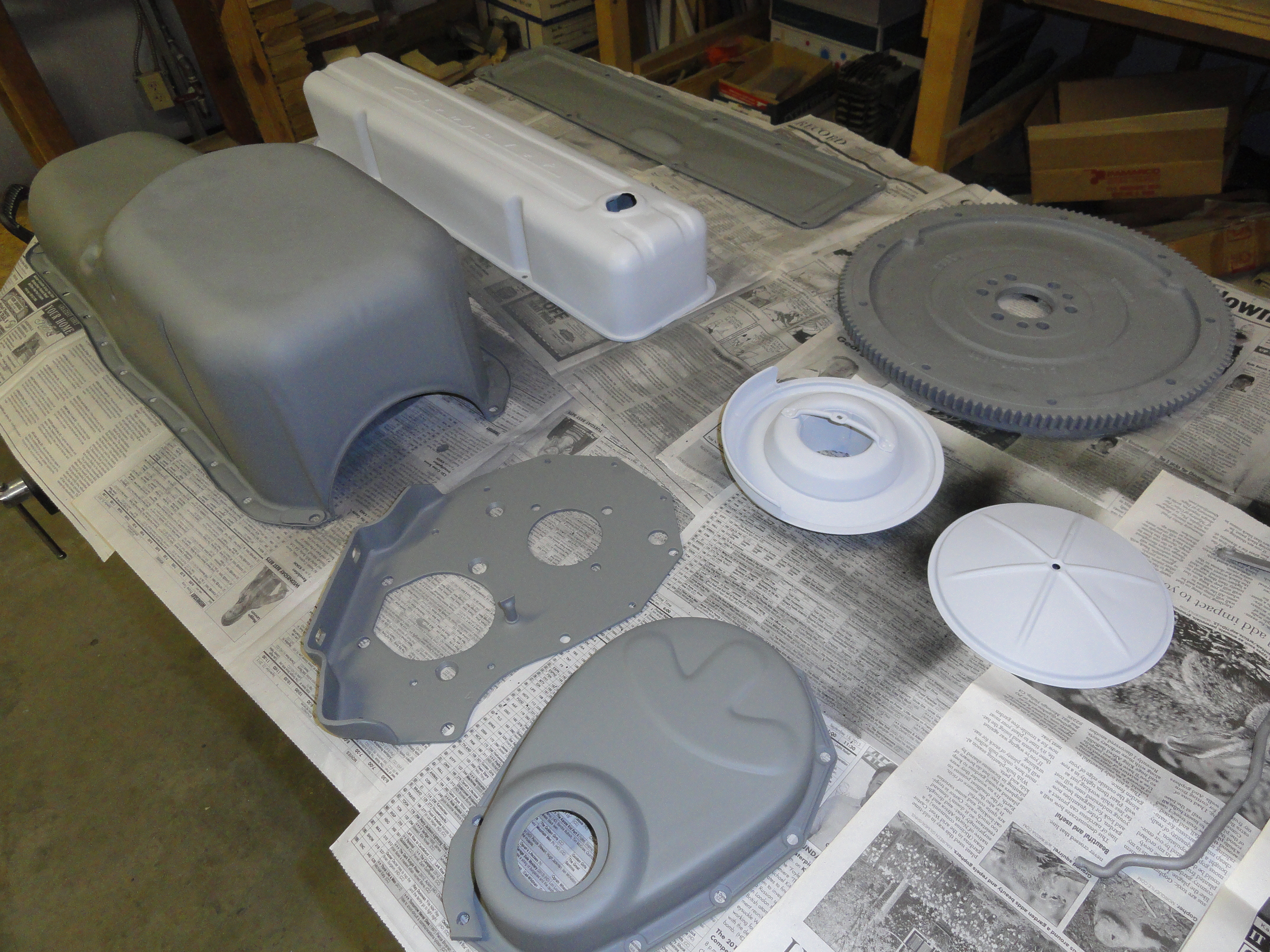
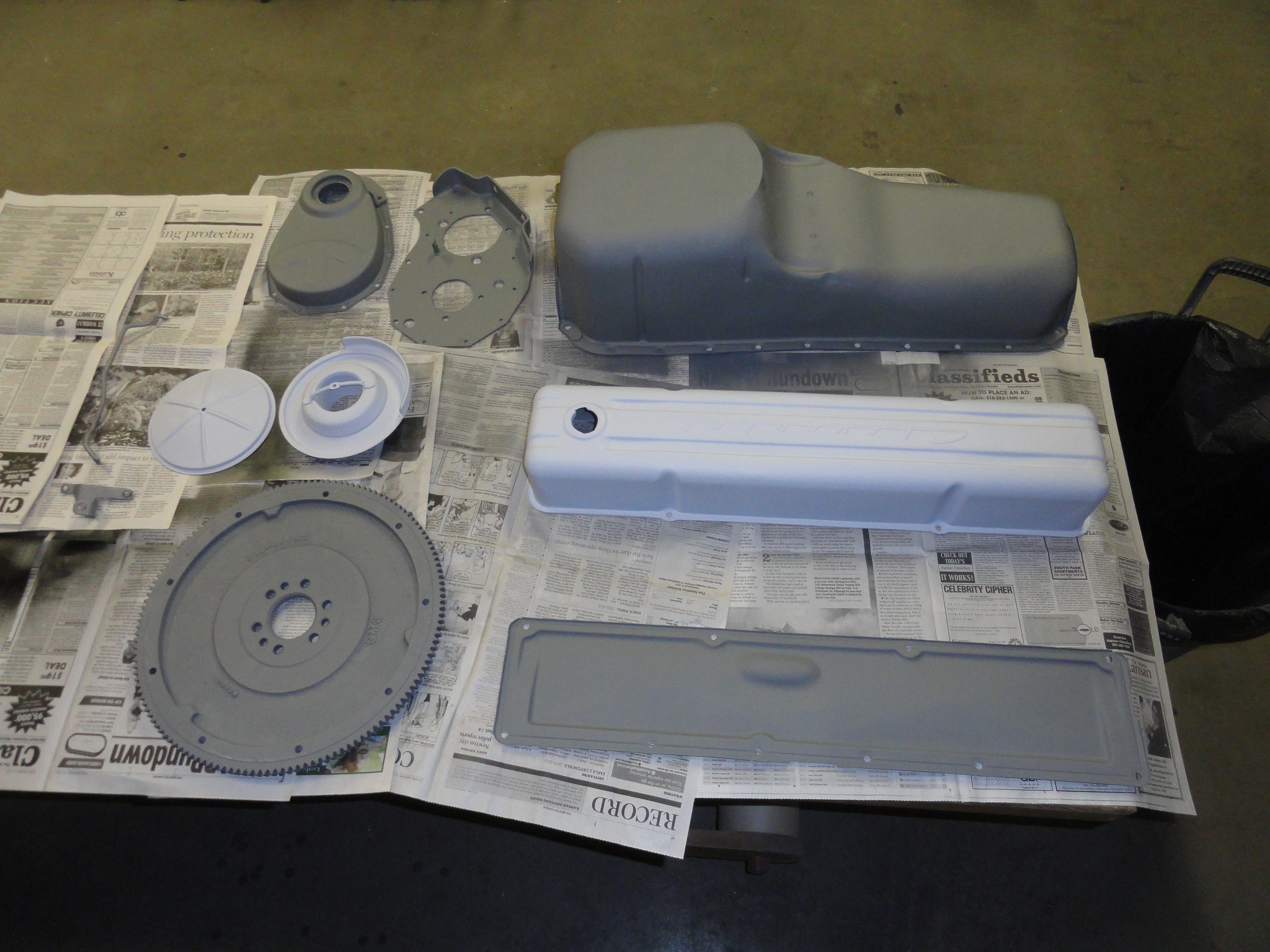
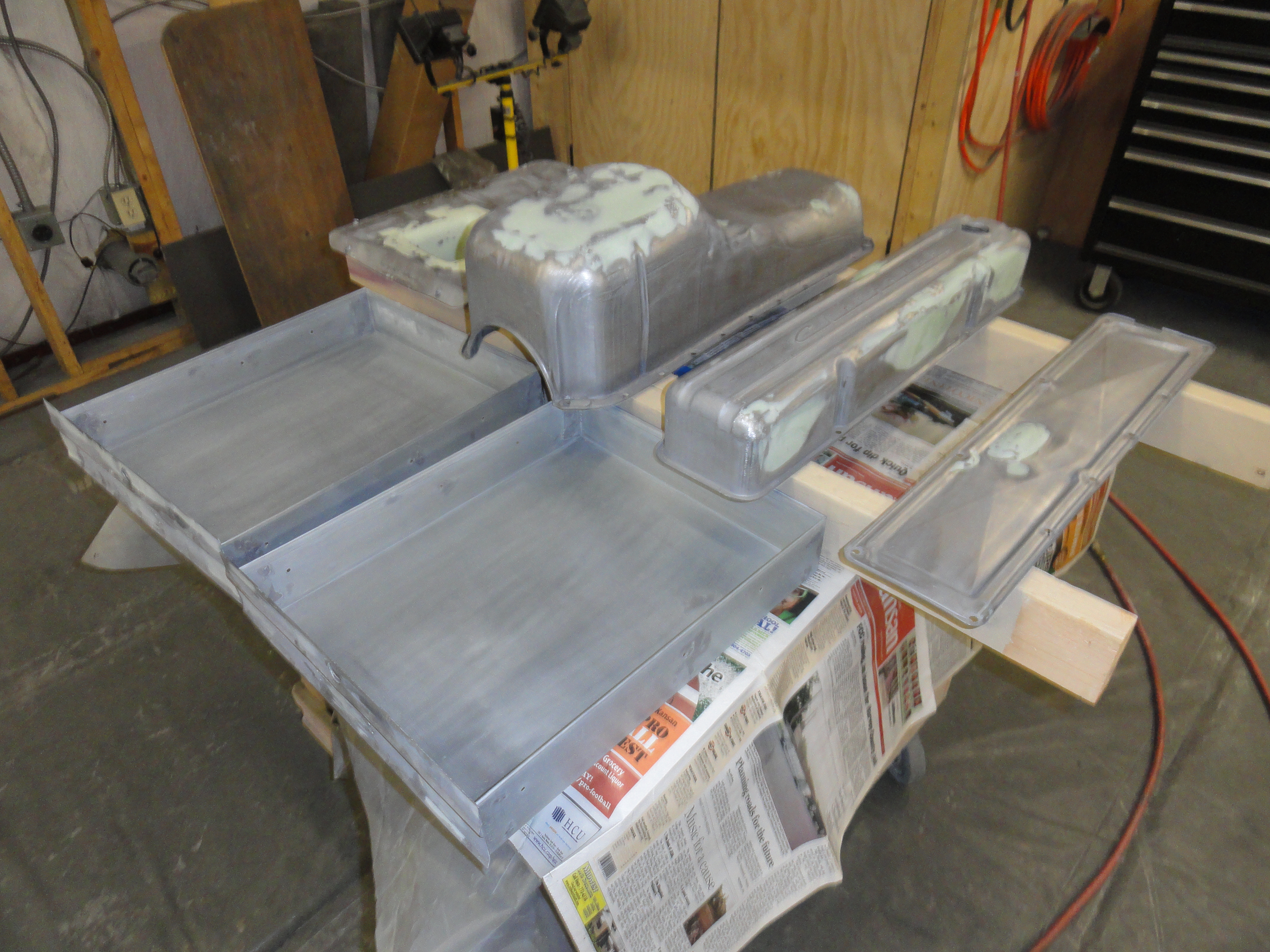
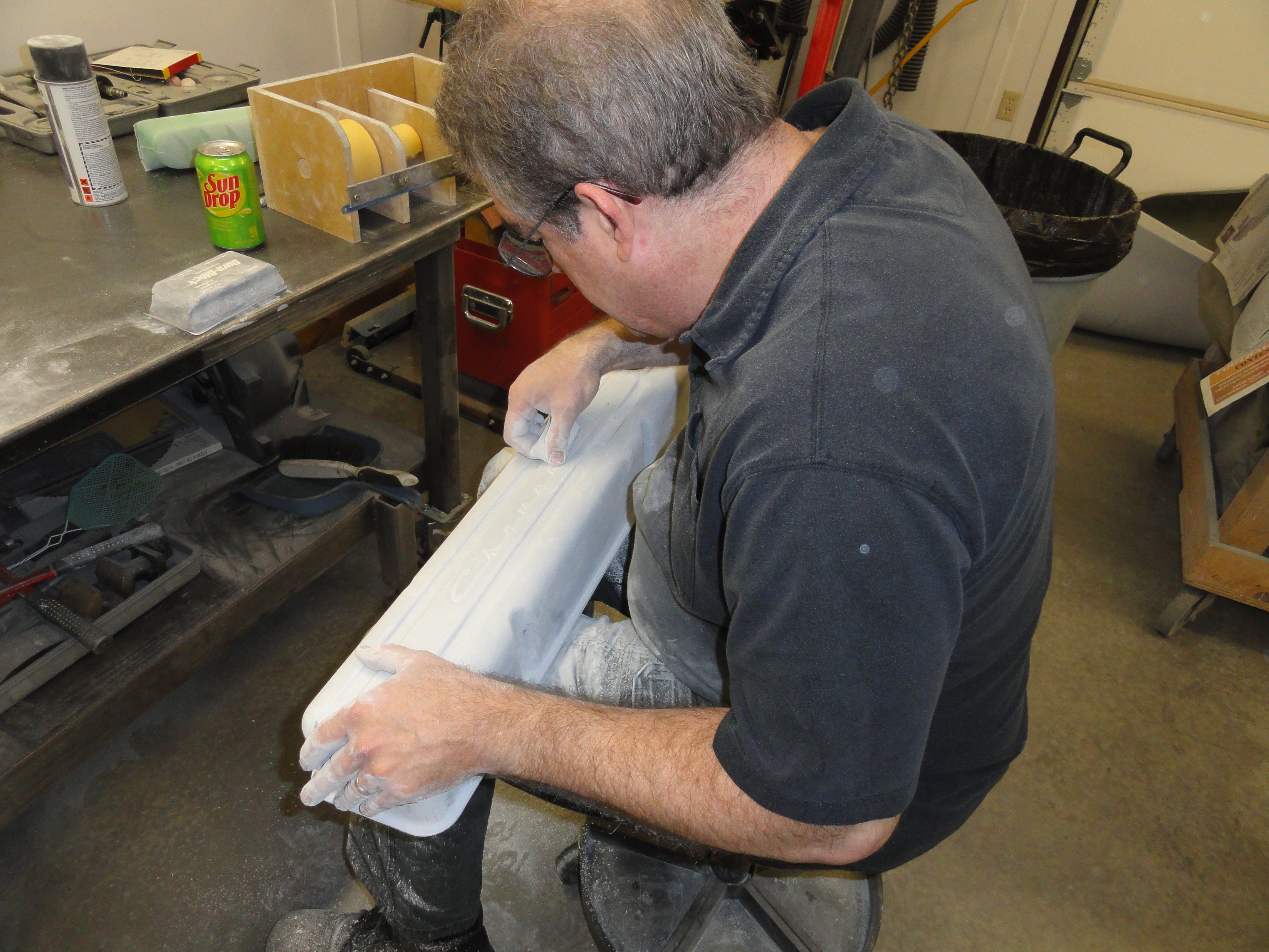
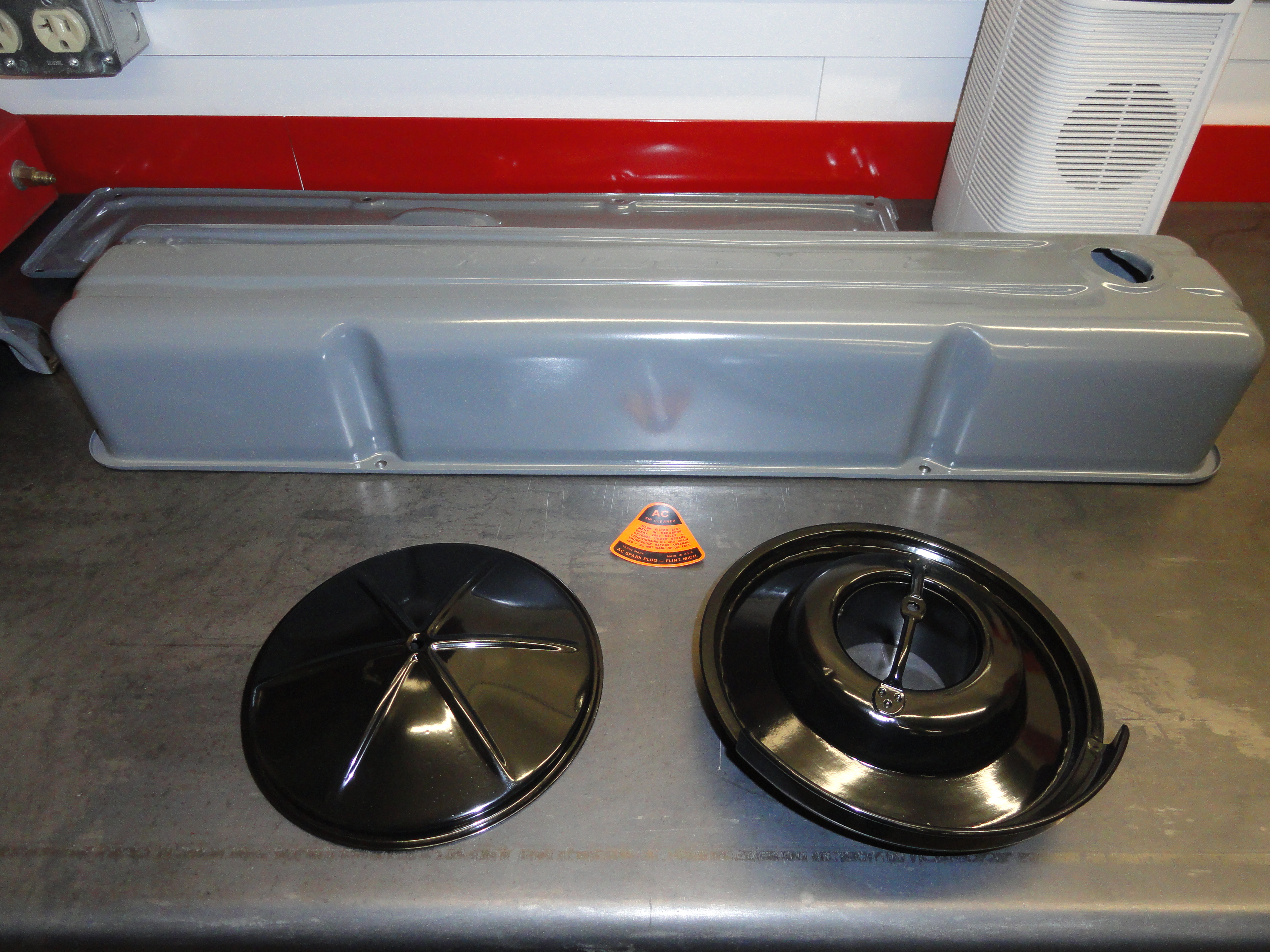
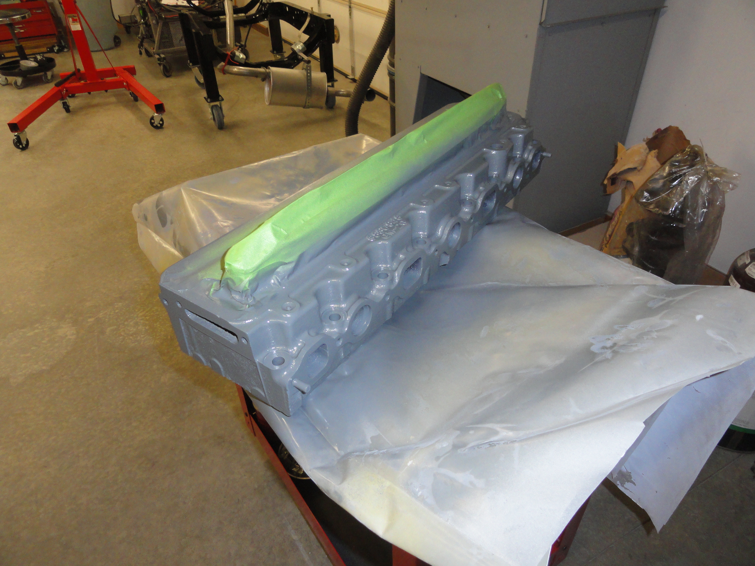
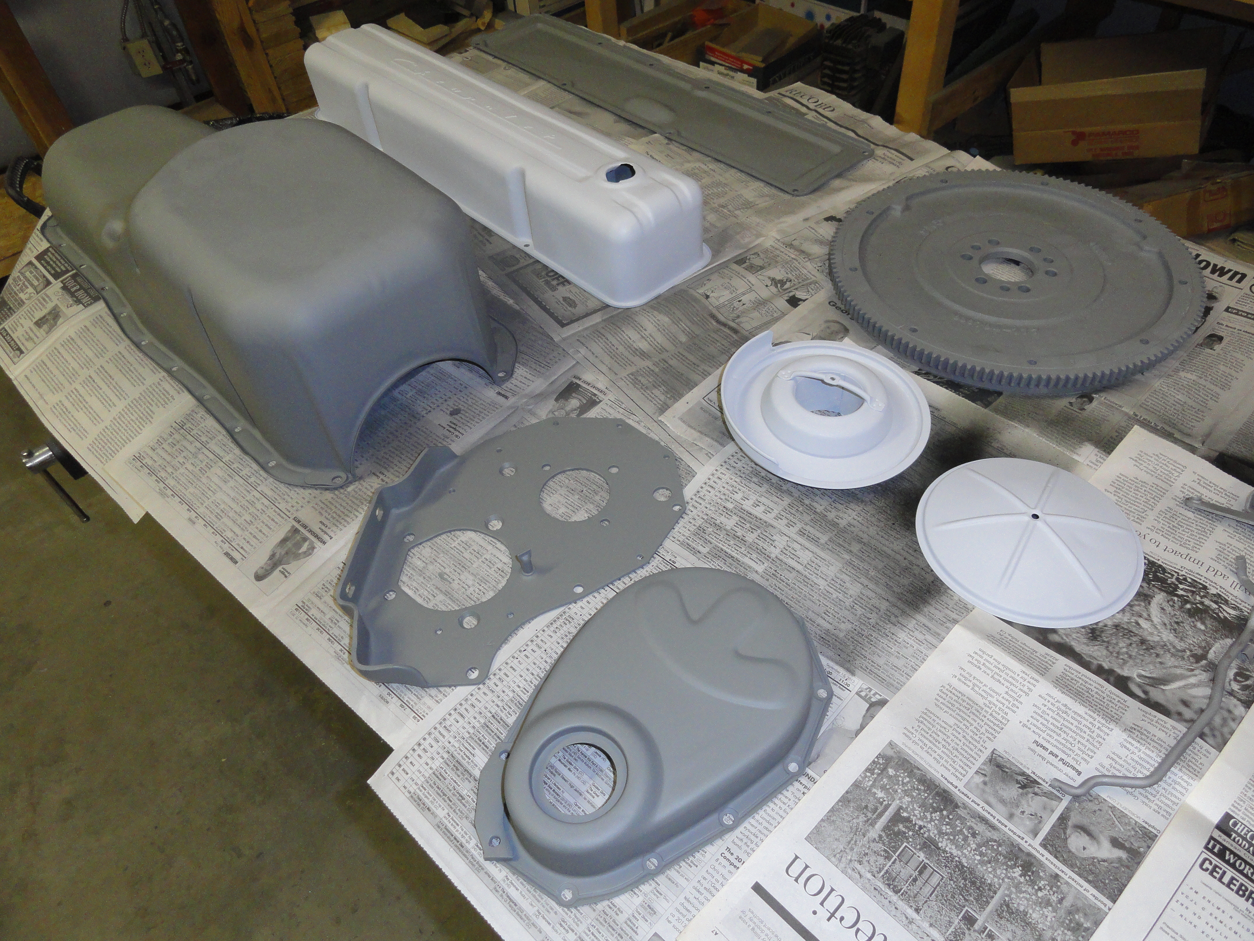
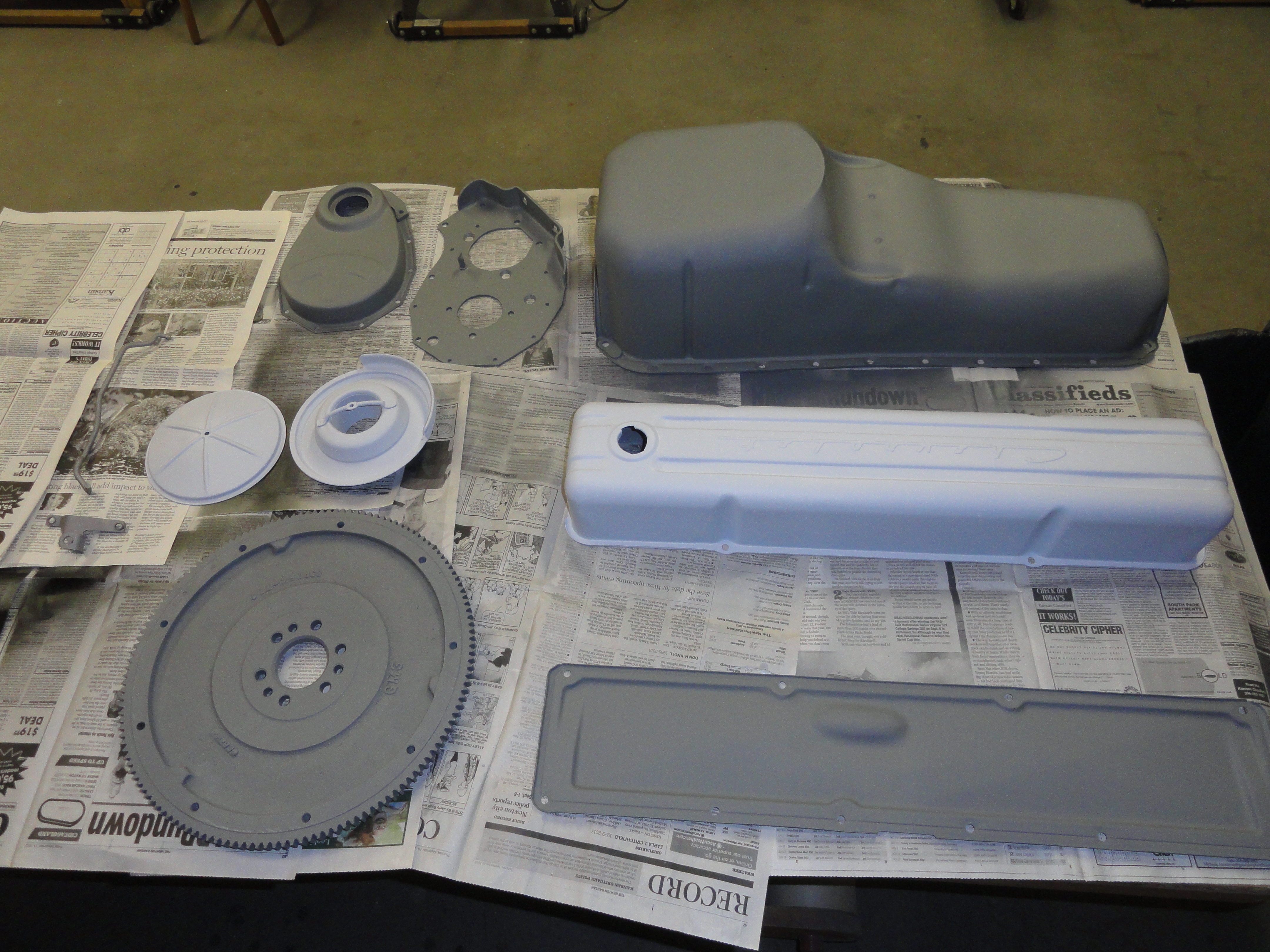
The way I look at it, this venerable old engine deserves the very best. Let's not get in the habit of cutting corners. With that in mind, there were many rust pits, dents, dings, deep scratches, cracked metal in the Oil Pan, Side Cover and Valve Cover. There was much hammer and dolly work to get them into shape. Once they are sandblasted, you can use 400 sandpaper on a long board to check most of the surface of these parts. I use a long board for areas I can get to with that, but a short DuraBloc to get in other places, and then if those don't get me there, I do it by hand. We are checking for flat and smooth. Once I have gotten the metal 95% there, I will apply a few thick coats of DPLF Epoxy Primer to the surface and then finish sand with 400 grit. PPG's DPLF came highly recommended for engine tin because it is good for 500 degrees safely and once it's dry, you can apply rattle can Engine Paint right over it.
I was not particularly impressed with the condition of the engine sheet metal and it required many hours of work, but doing this in the way
I described preserves the tin and makes additional rust virtually impossible. Oil Pan, Side Cover, Timing Cover and Valve Cover get no paint
on the inside. Very important to NOT introduce possible contaminants into the engine internals. Once the outside is complete and dry, apply
motor oil to the inside surfaces letting the oil soak into the metal.
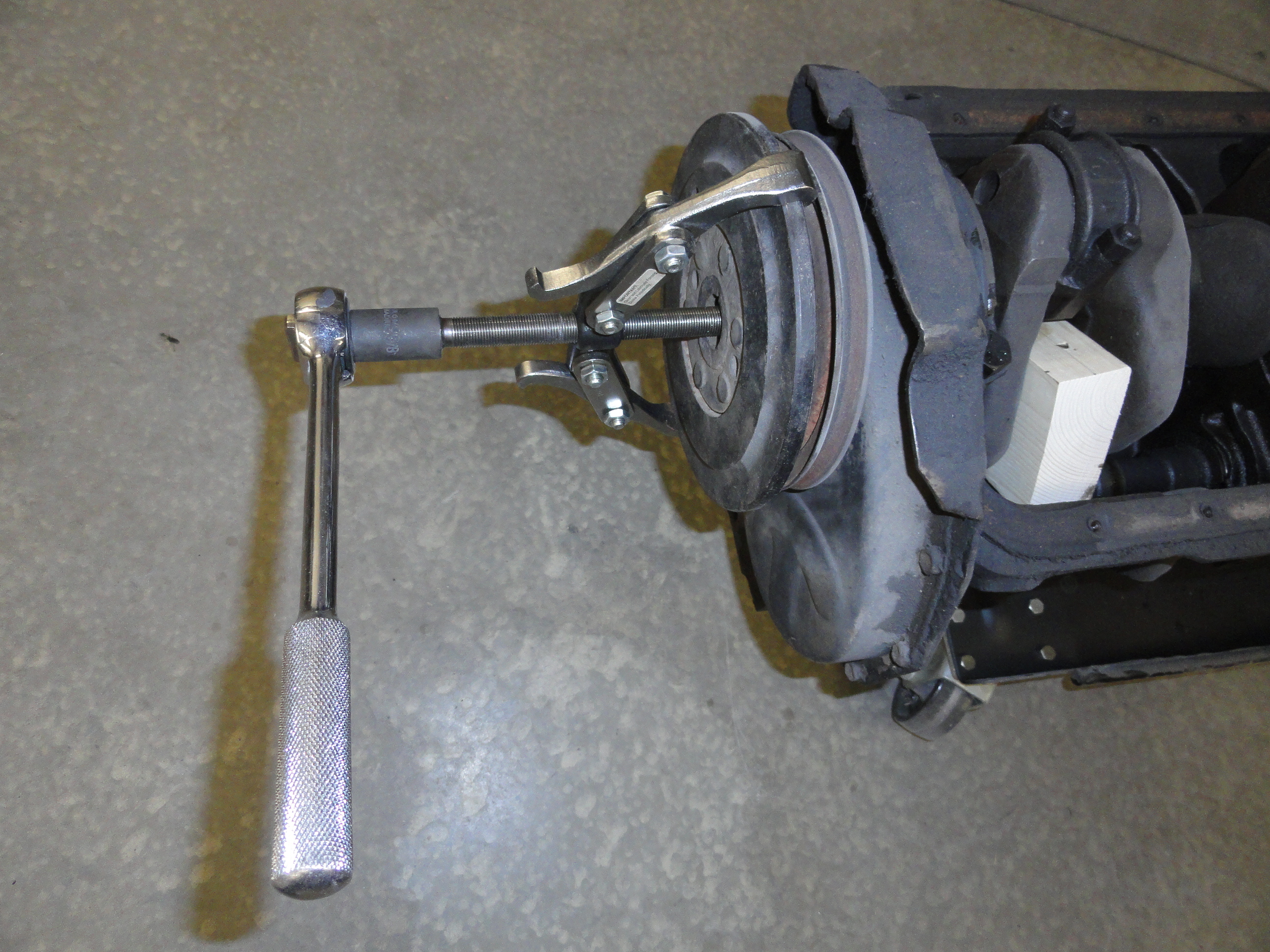

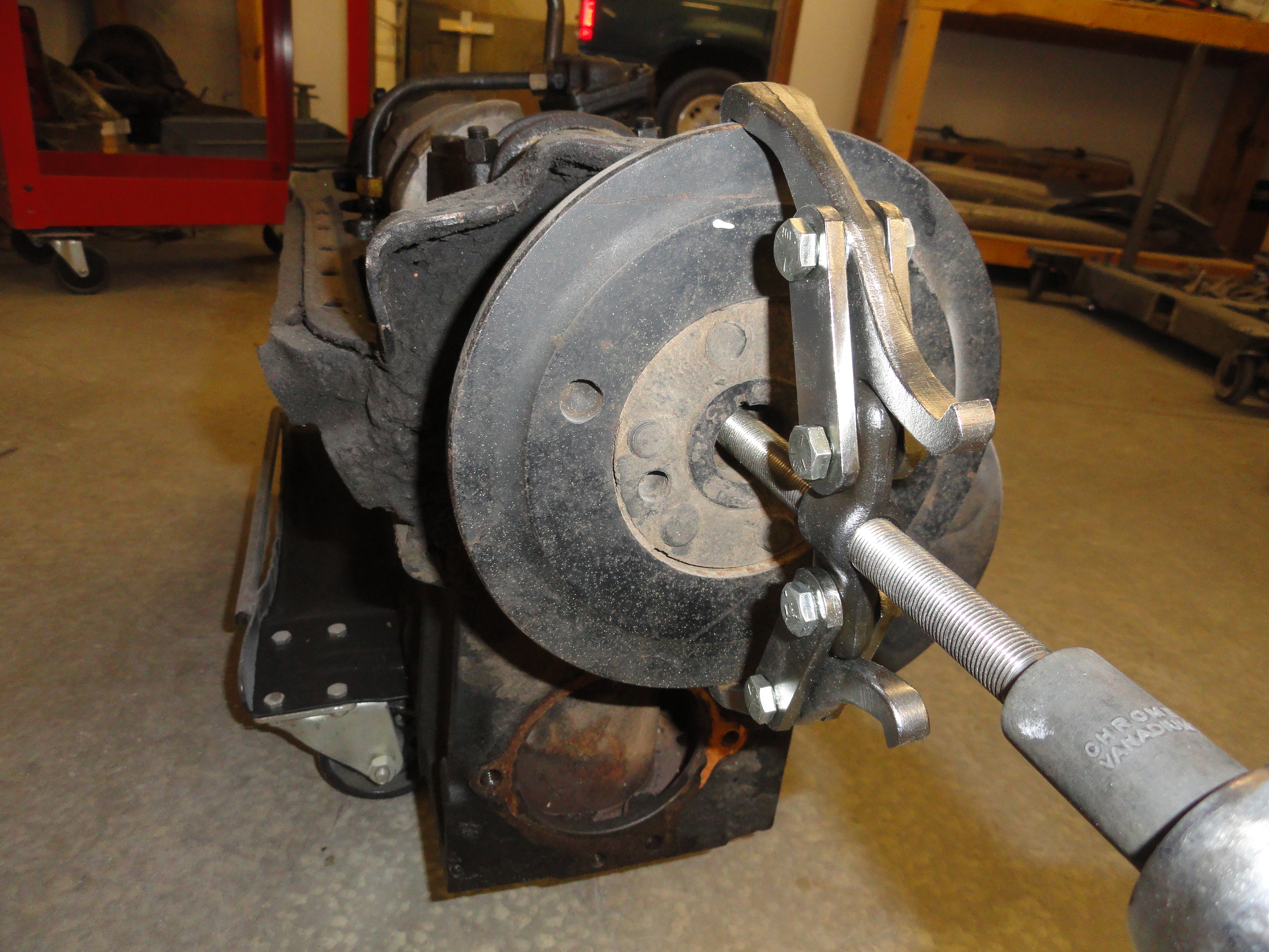
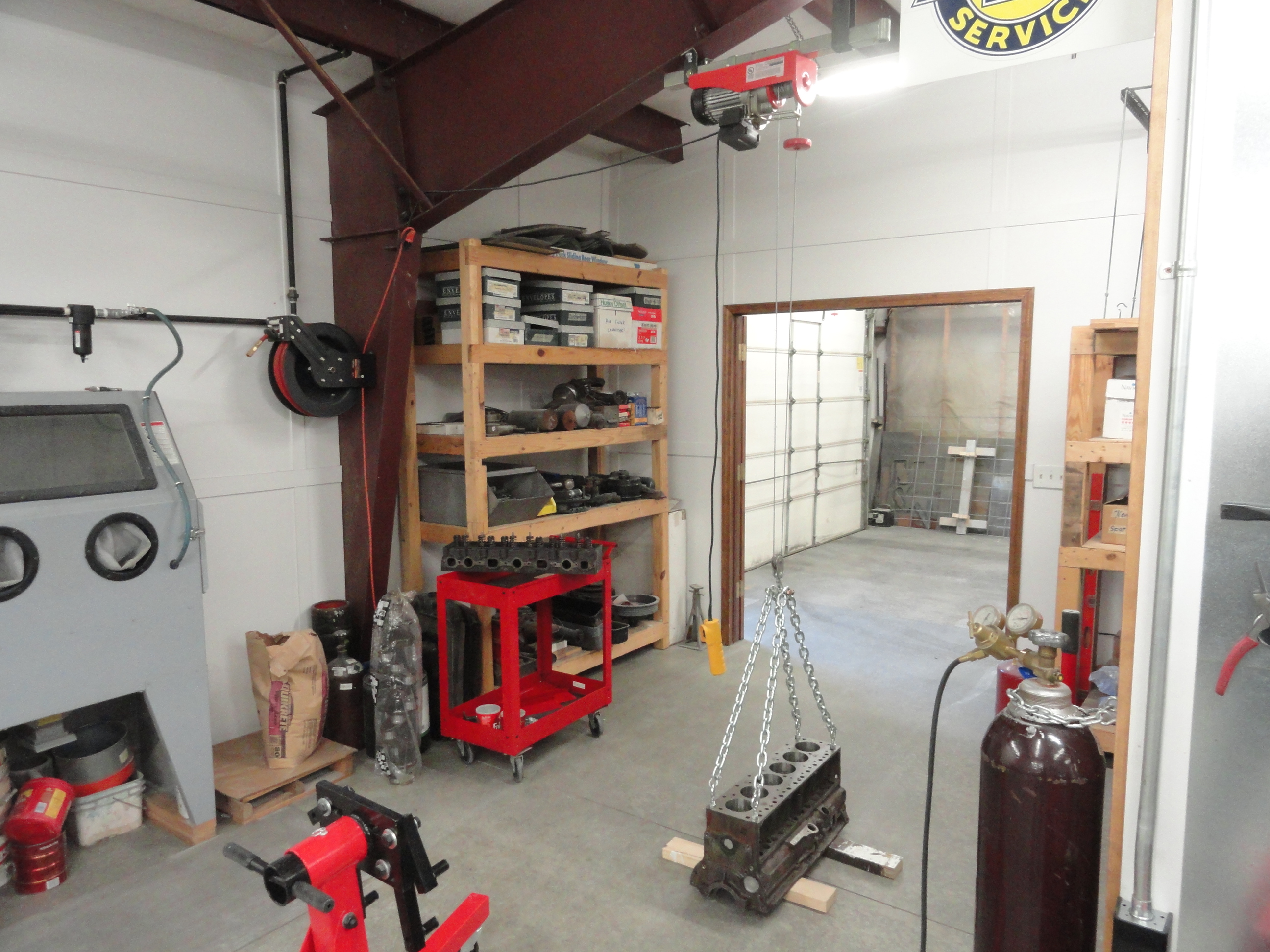
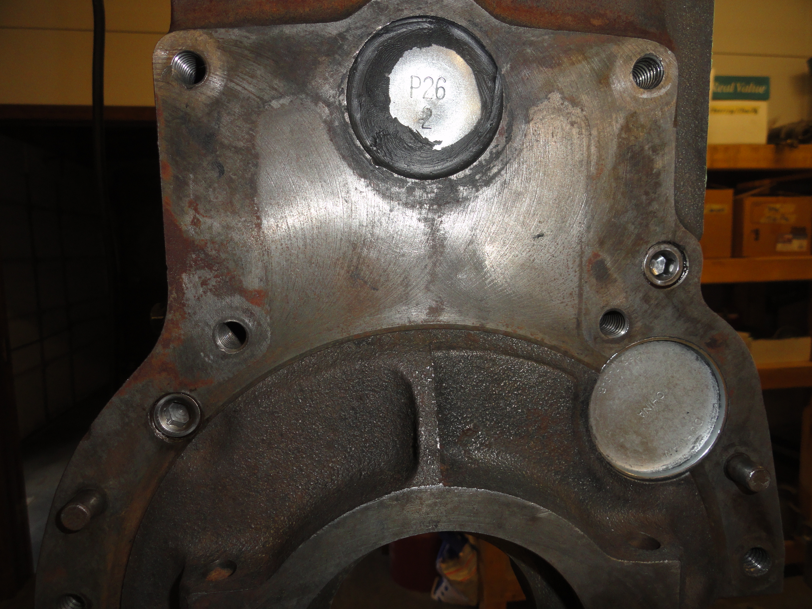
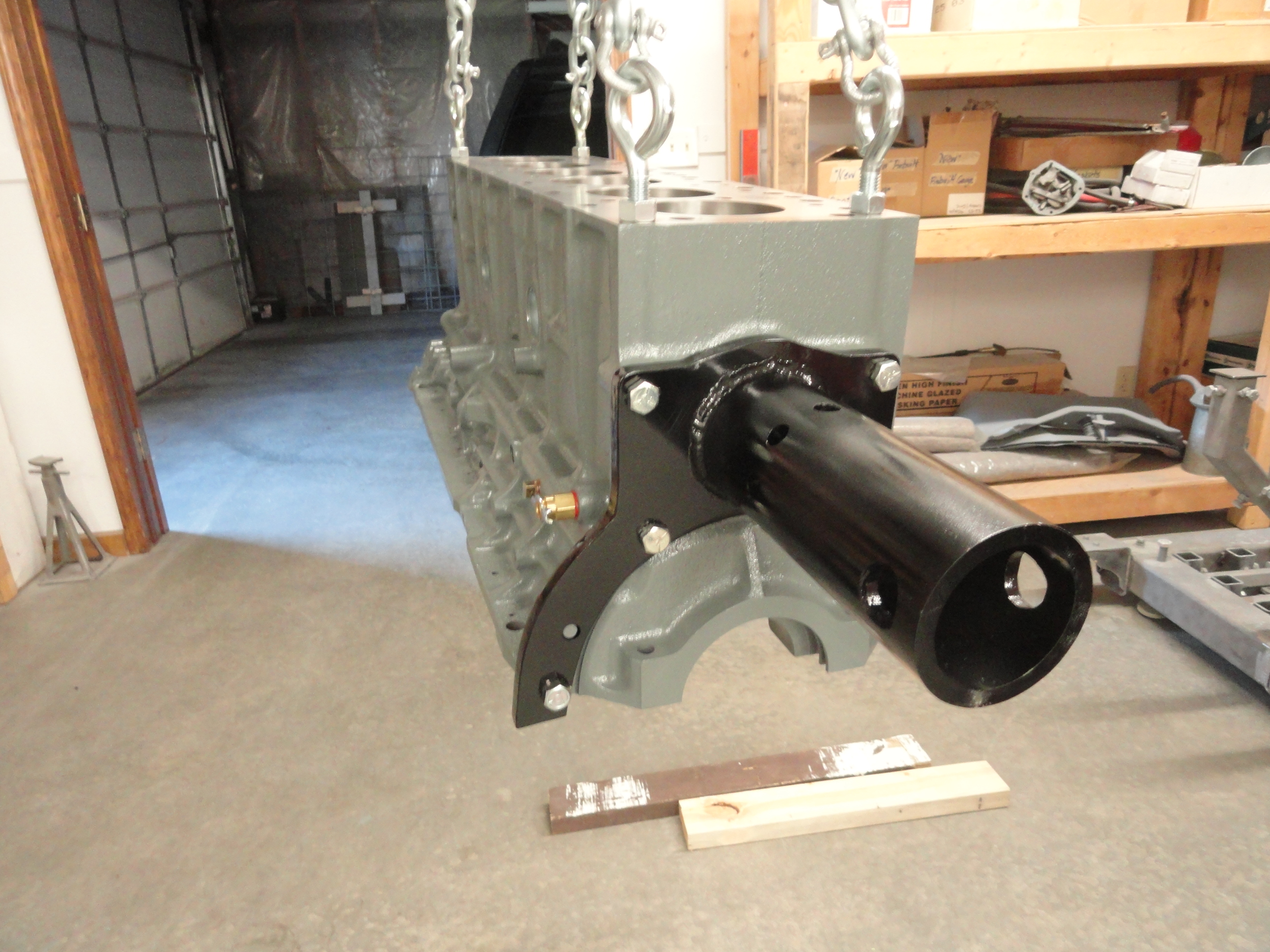
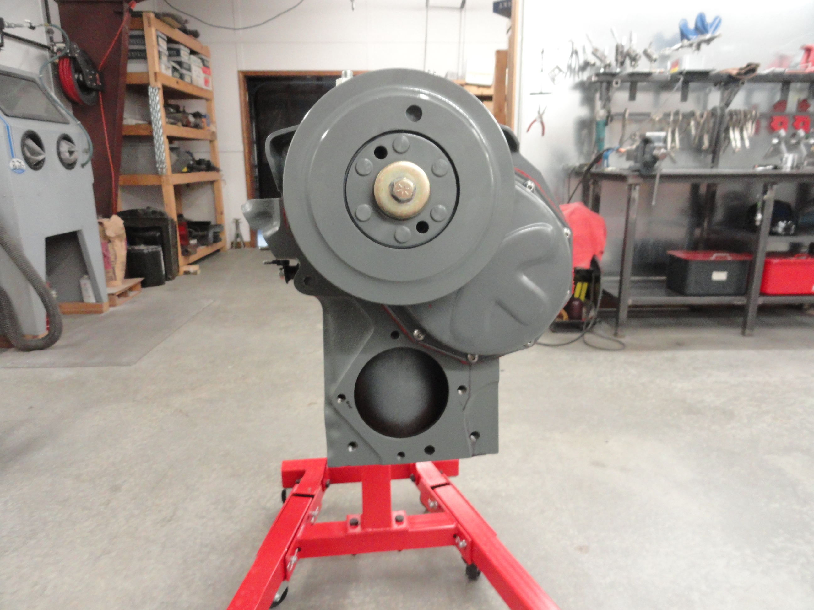
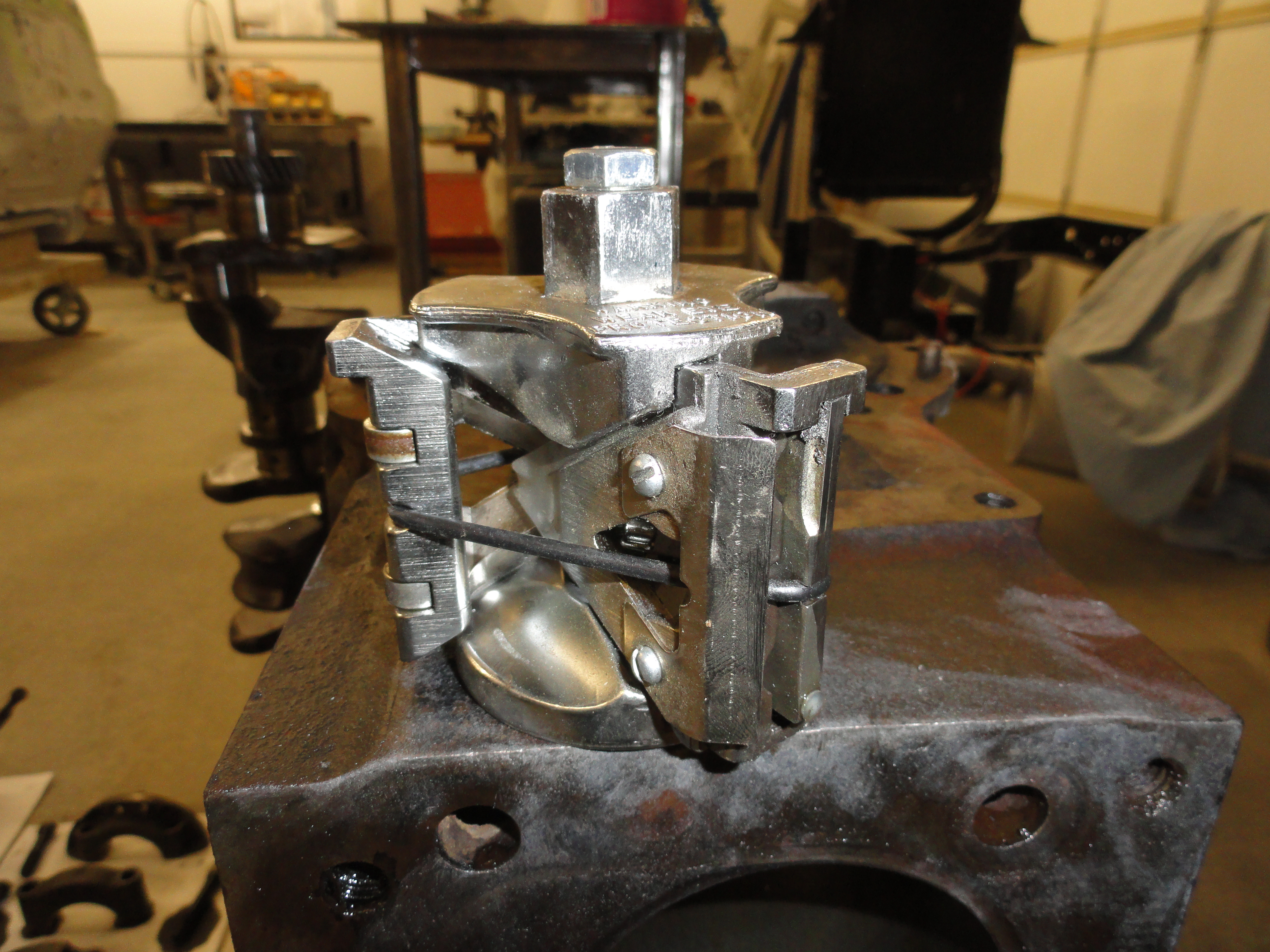
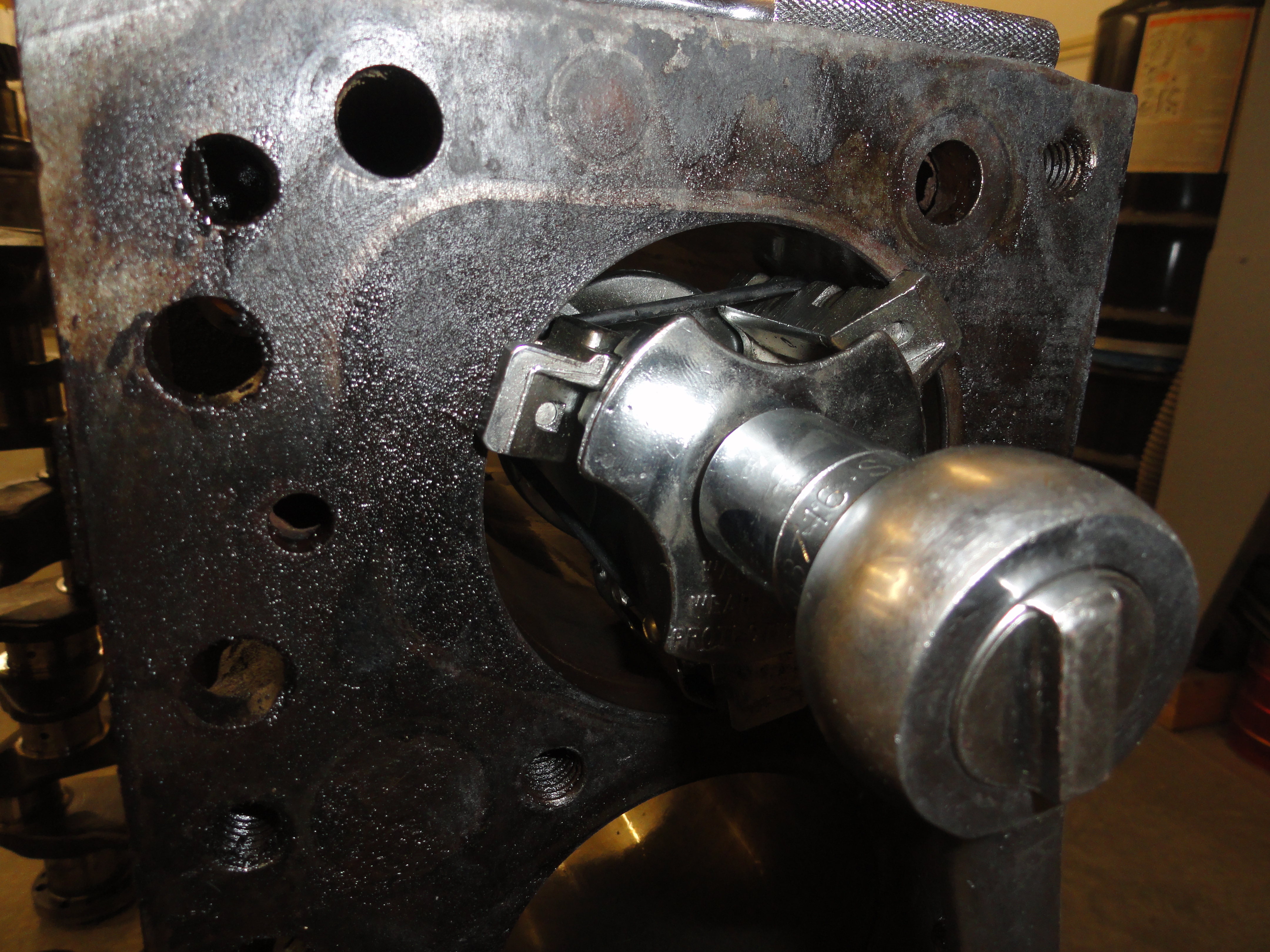
First order of business is to get the Harmonic Balancer off. This is easily done but there is sort of a secret to it. Some of these balancers have been on the engine a long time and you might over-stress your Puller if you don't lightly tap on the edge of the balancer as you are tightening your puller. If you lightly tap the edge, it will just smoothly walk right off of the crankshaft. Notice the piece of wood lodged into the crankshafts rotation. This is to make the crank stop so you can get the balancer off. If you use a 2 prong puller like me, make sure you center it nice. It will come off easier. It was brought to my attention after the pictures were taken that maybe that puller is a bad choice. The balancer itself has two 3/8" threaded holes for using the proper style puller. This is more in accordance with the Shop Manual. The puller pictured in the Tools List is the one you need.
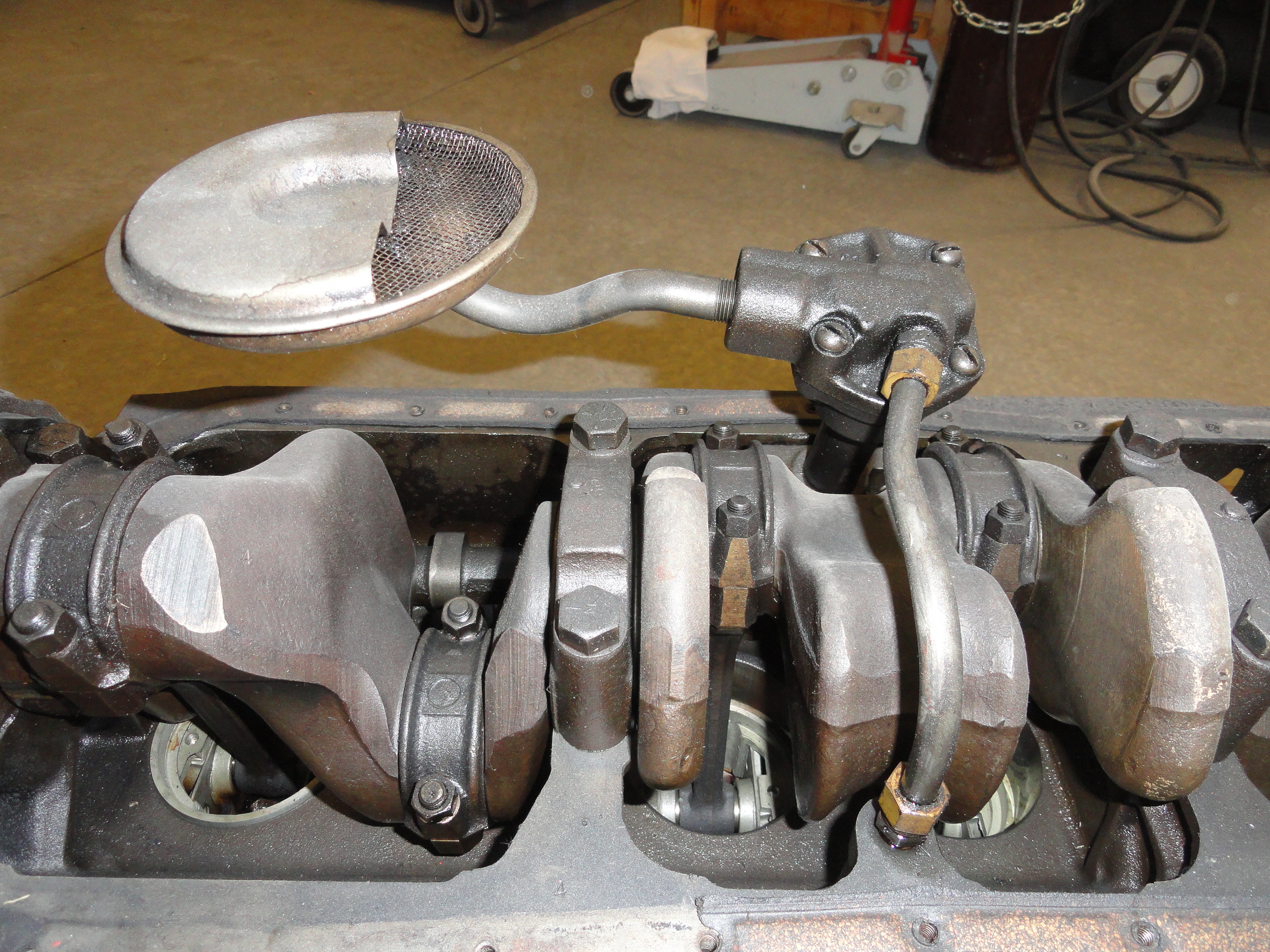
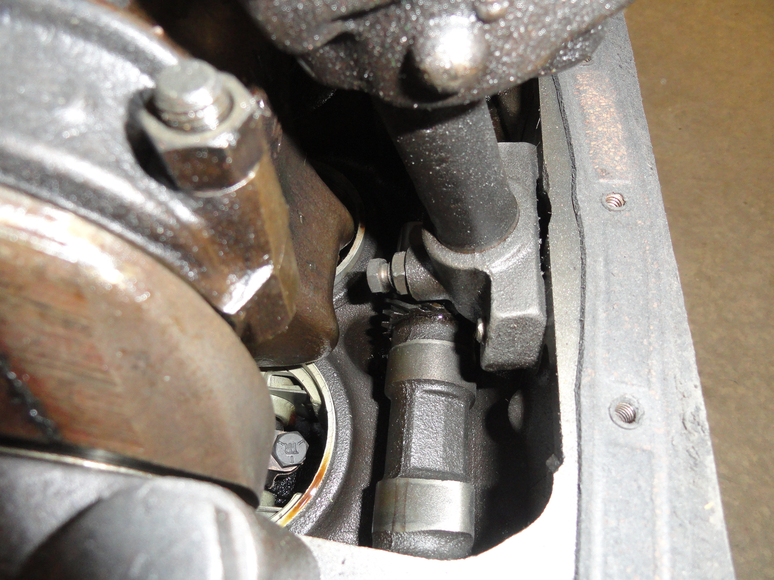
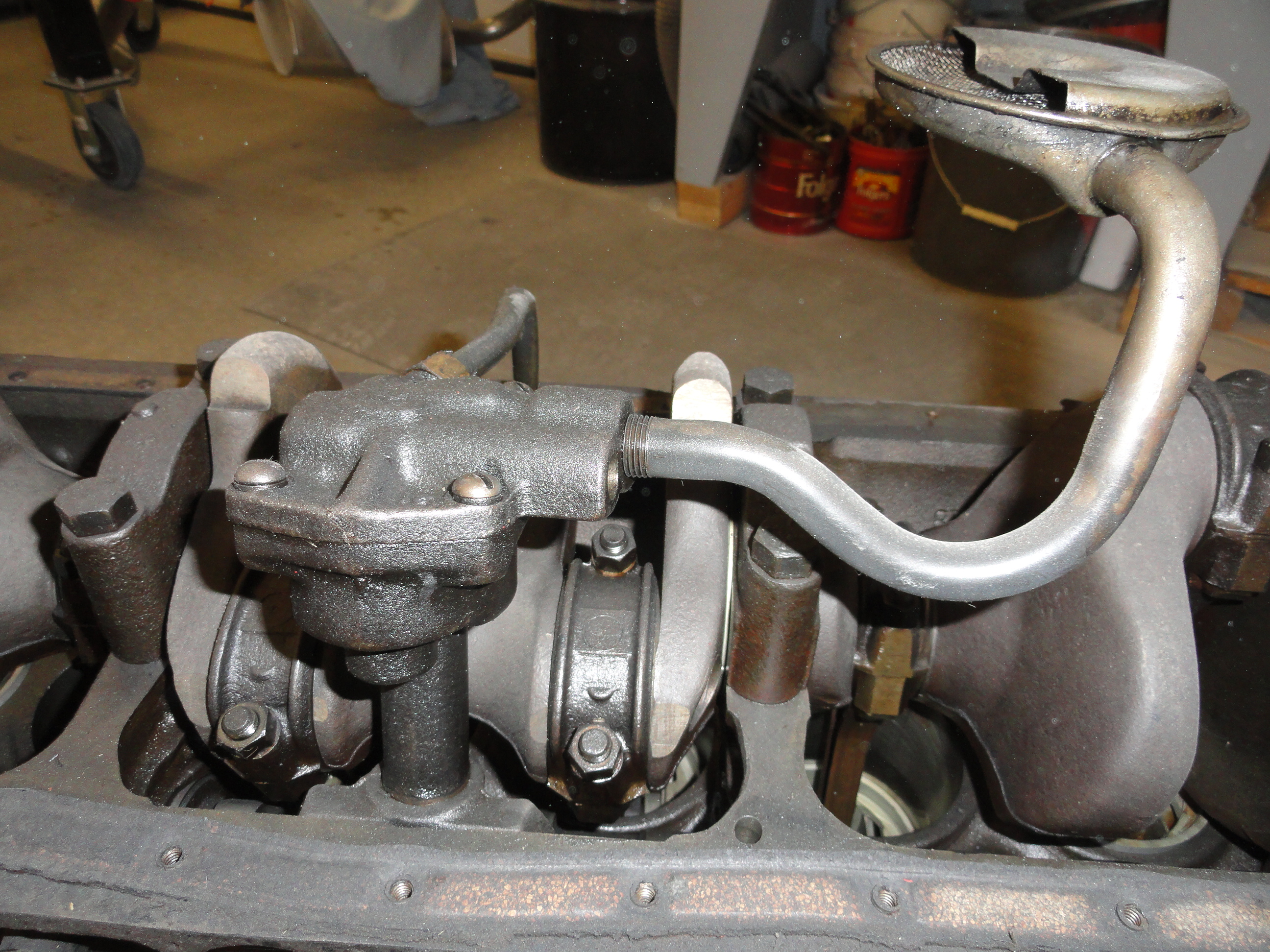
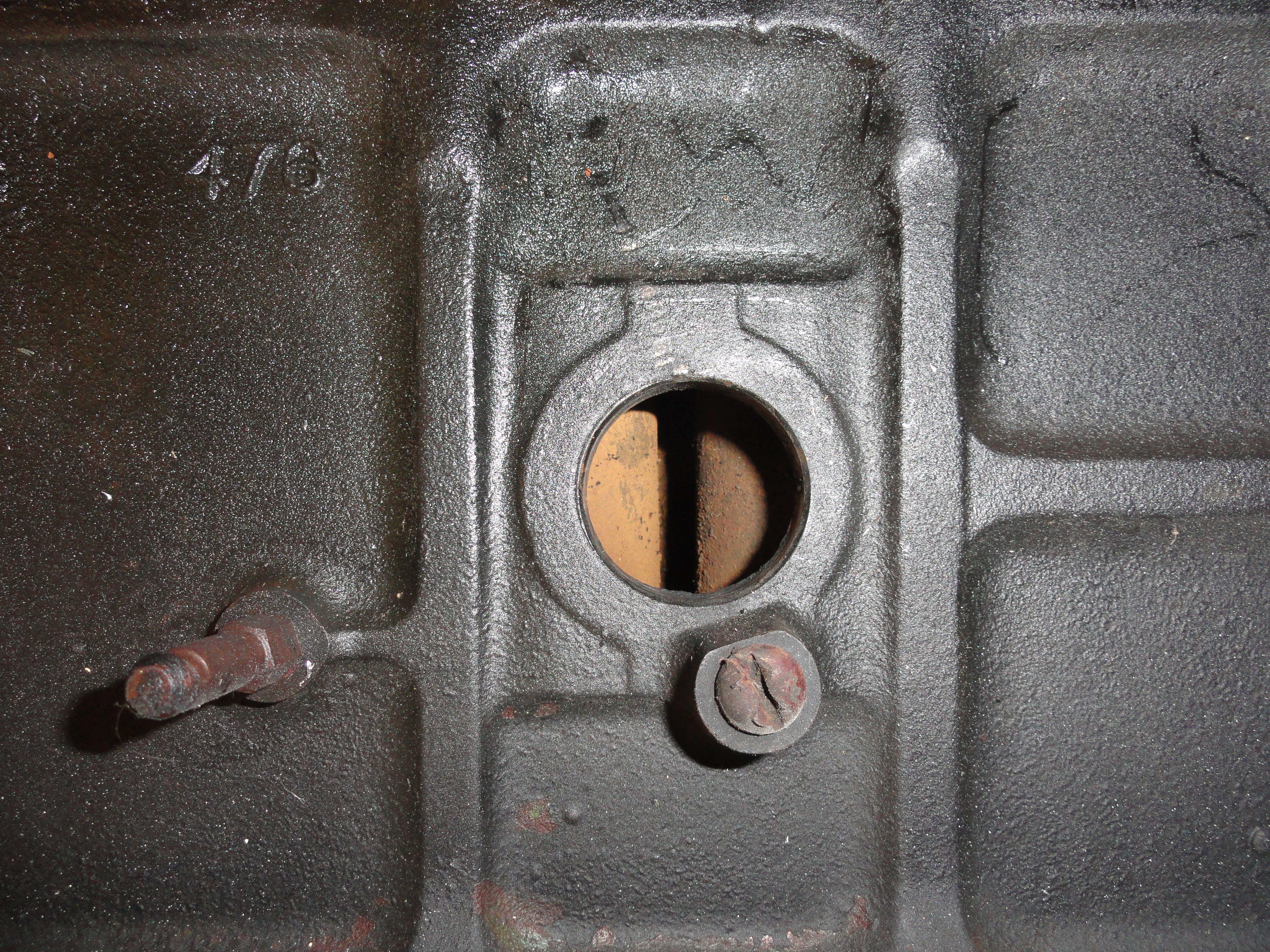
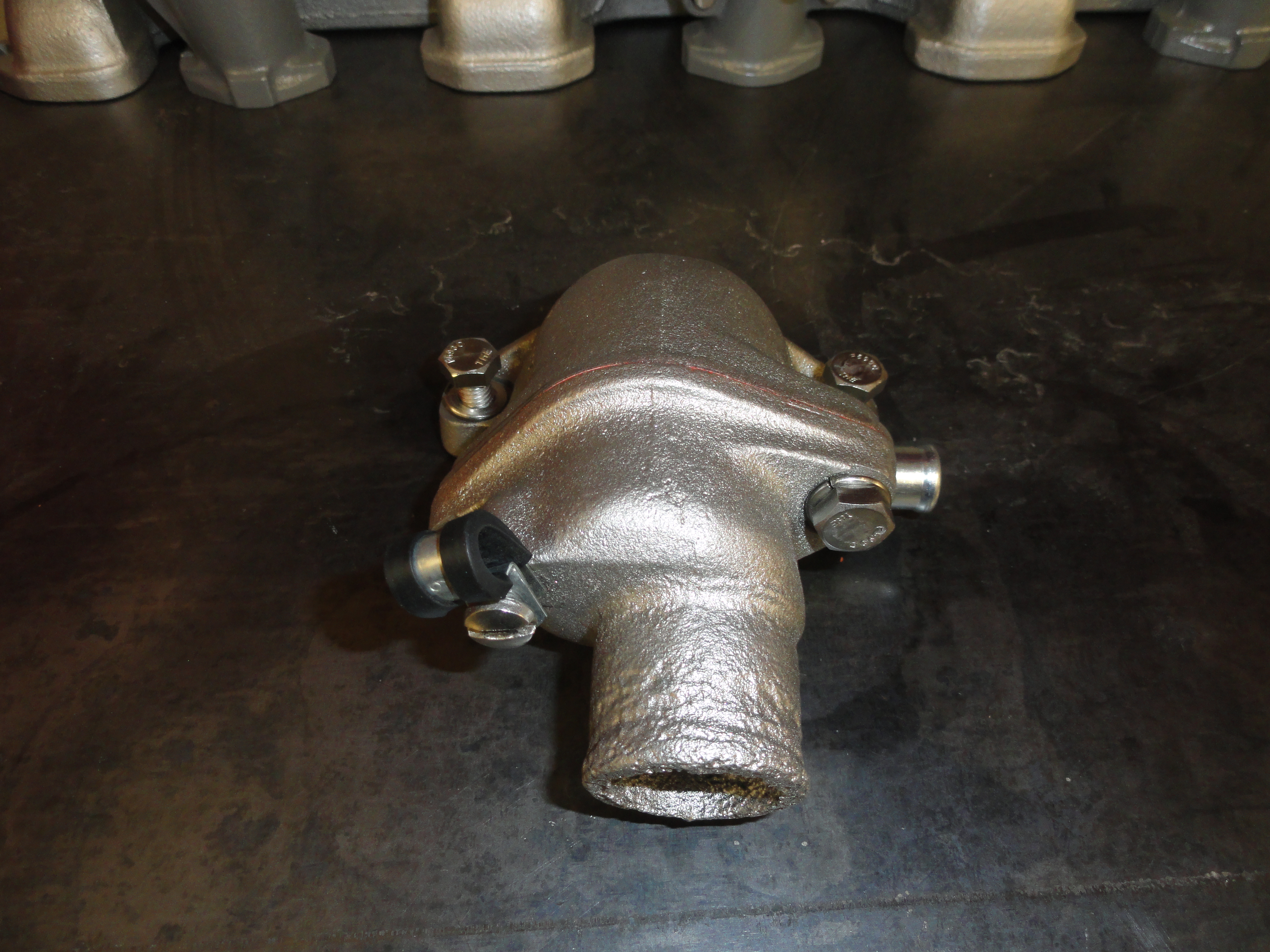
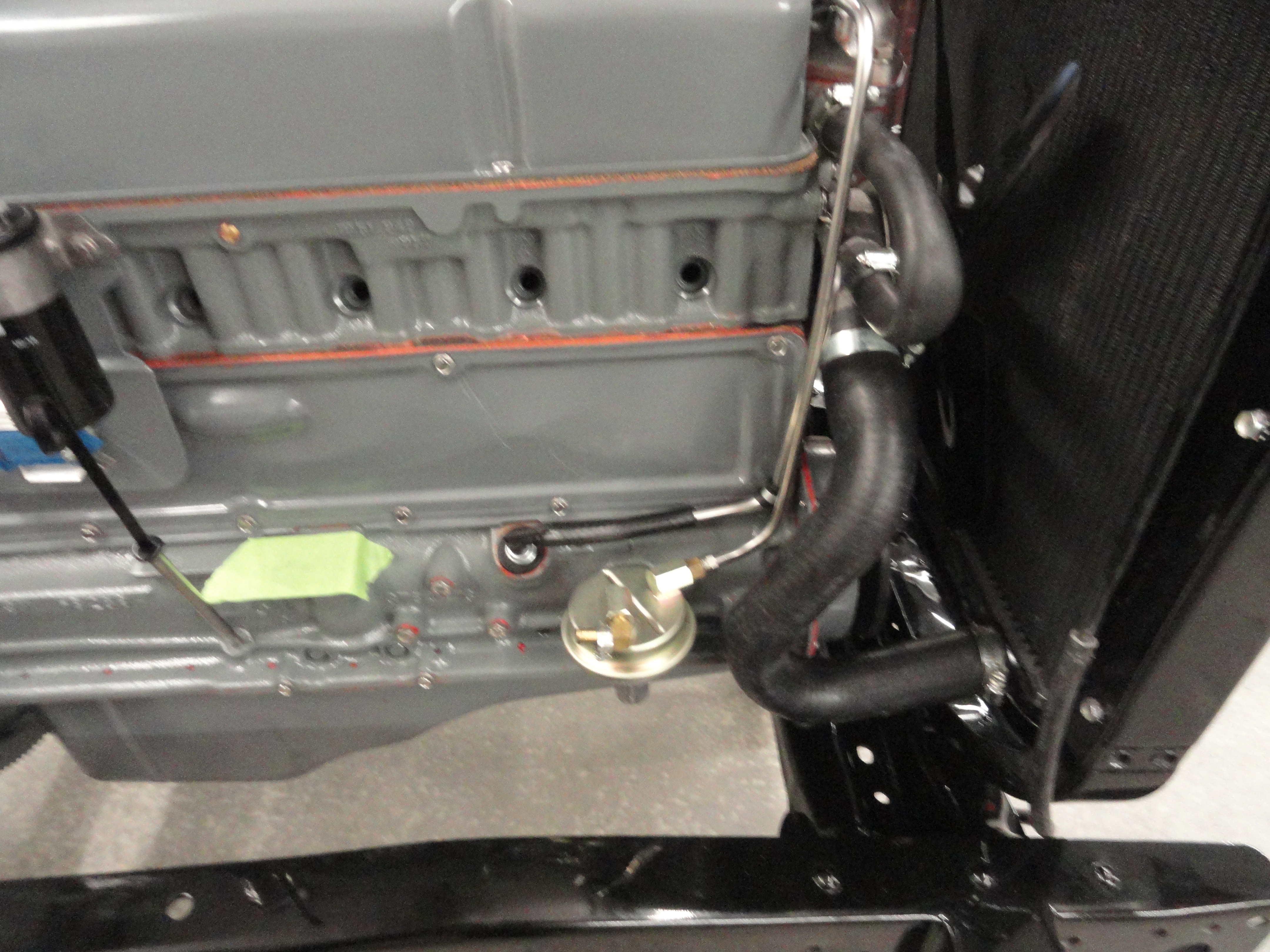
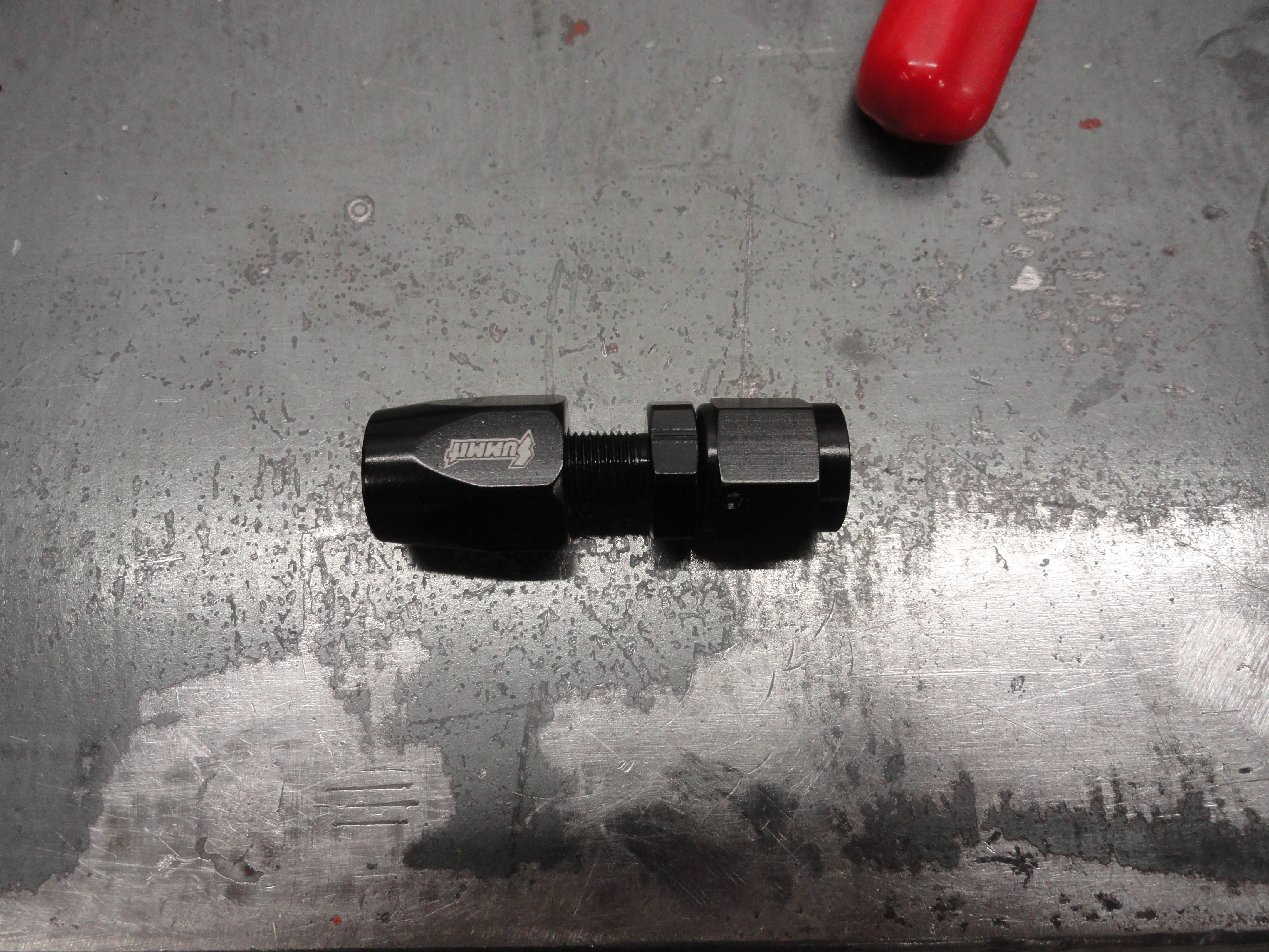
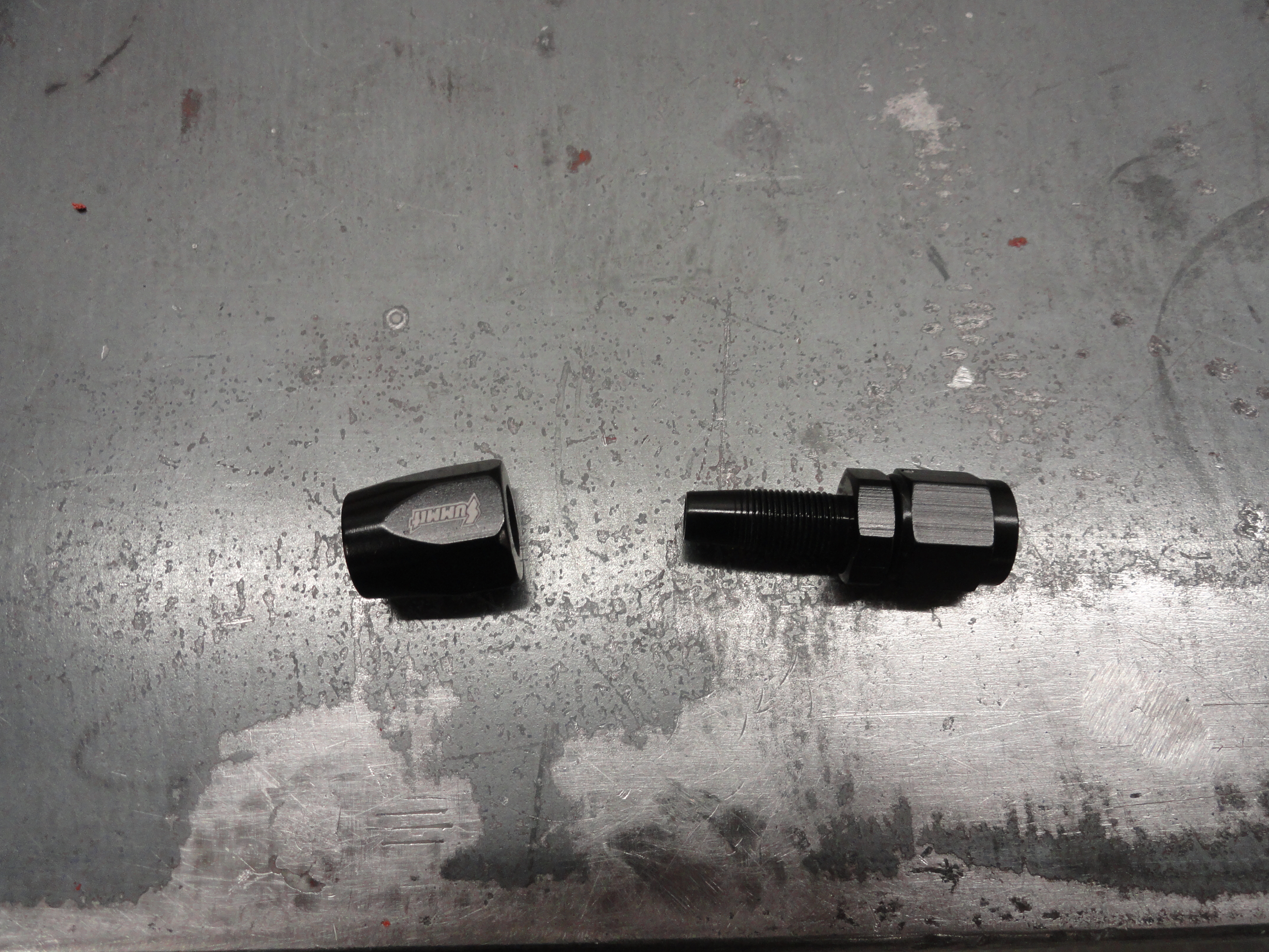
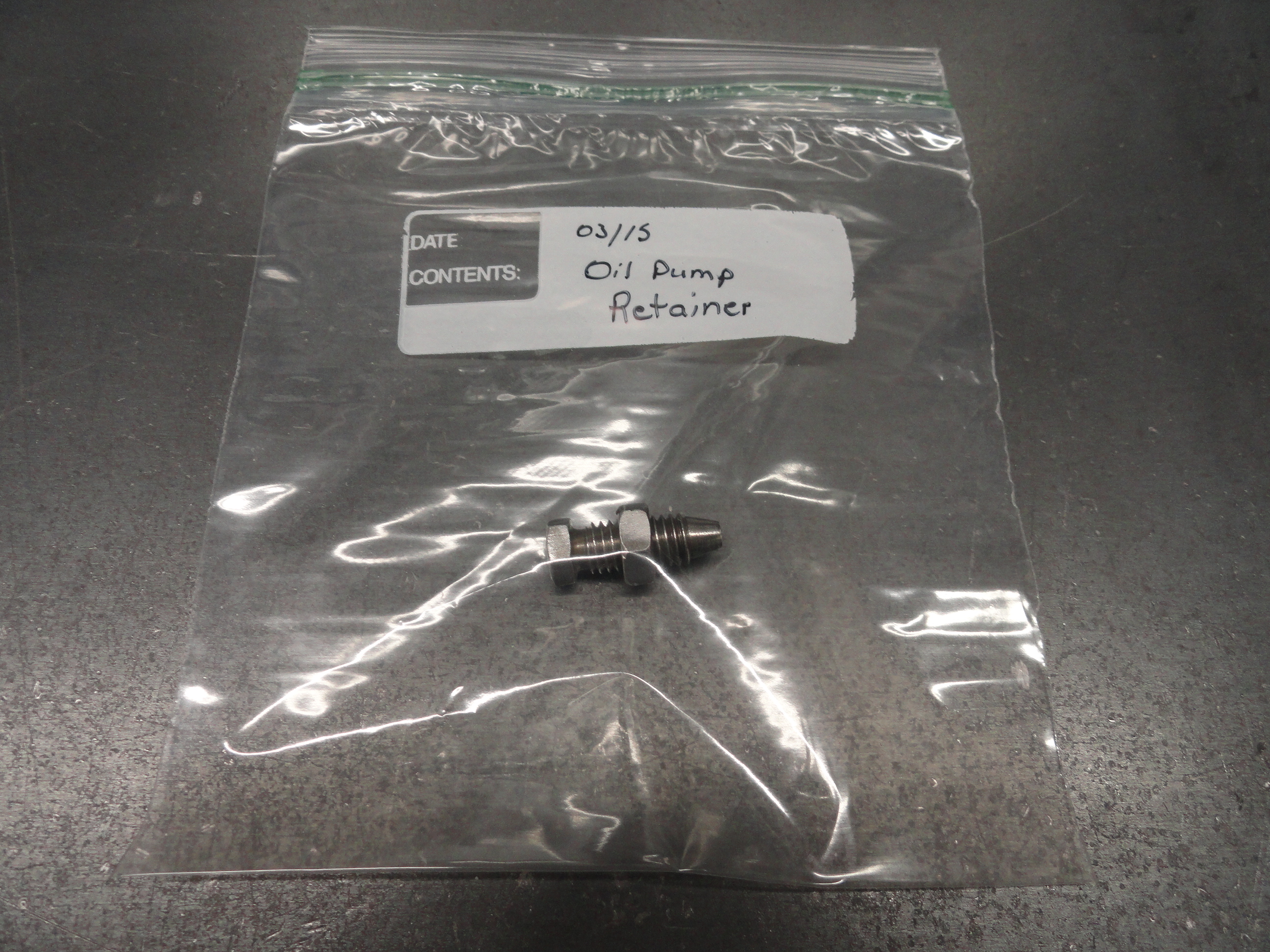
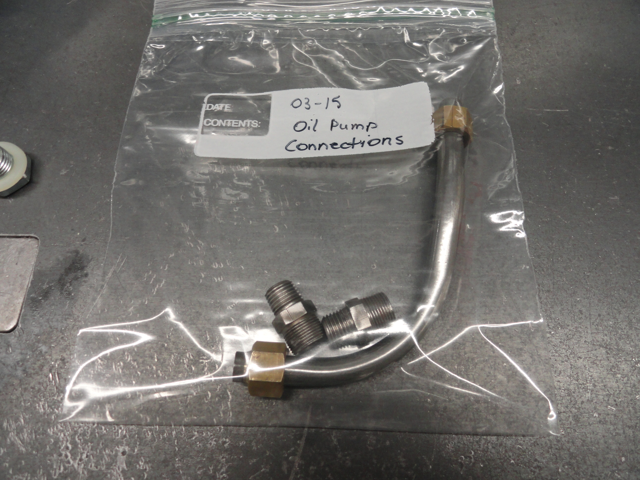
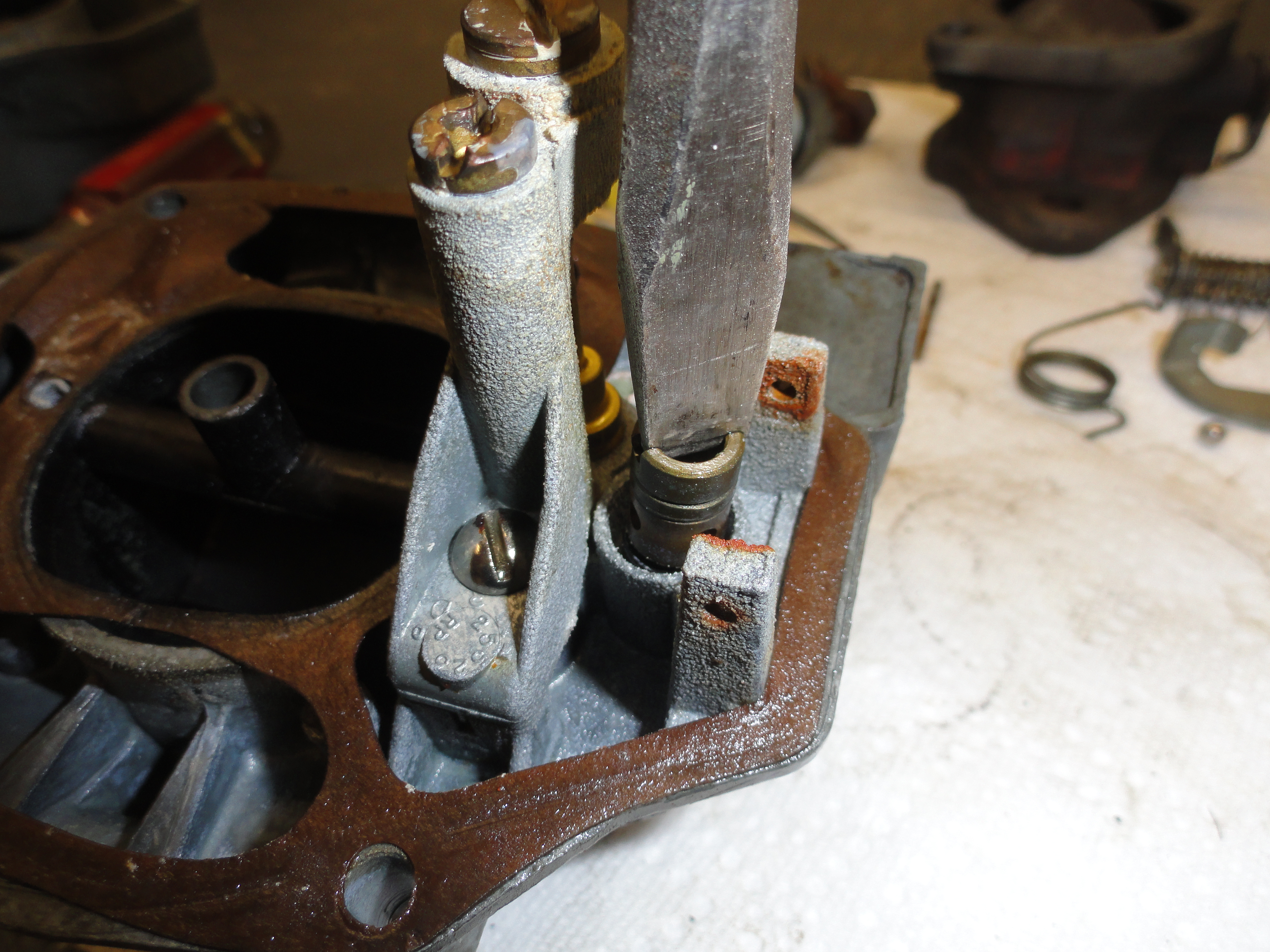
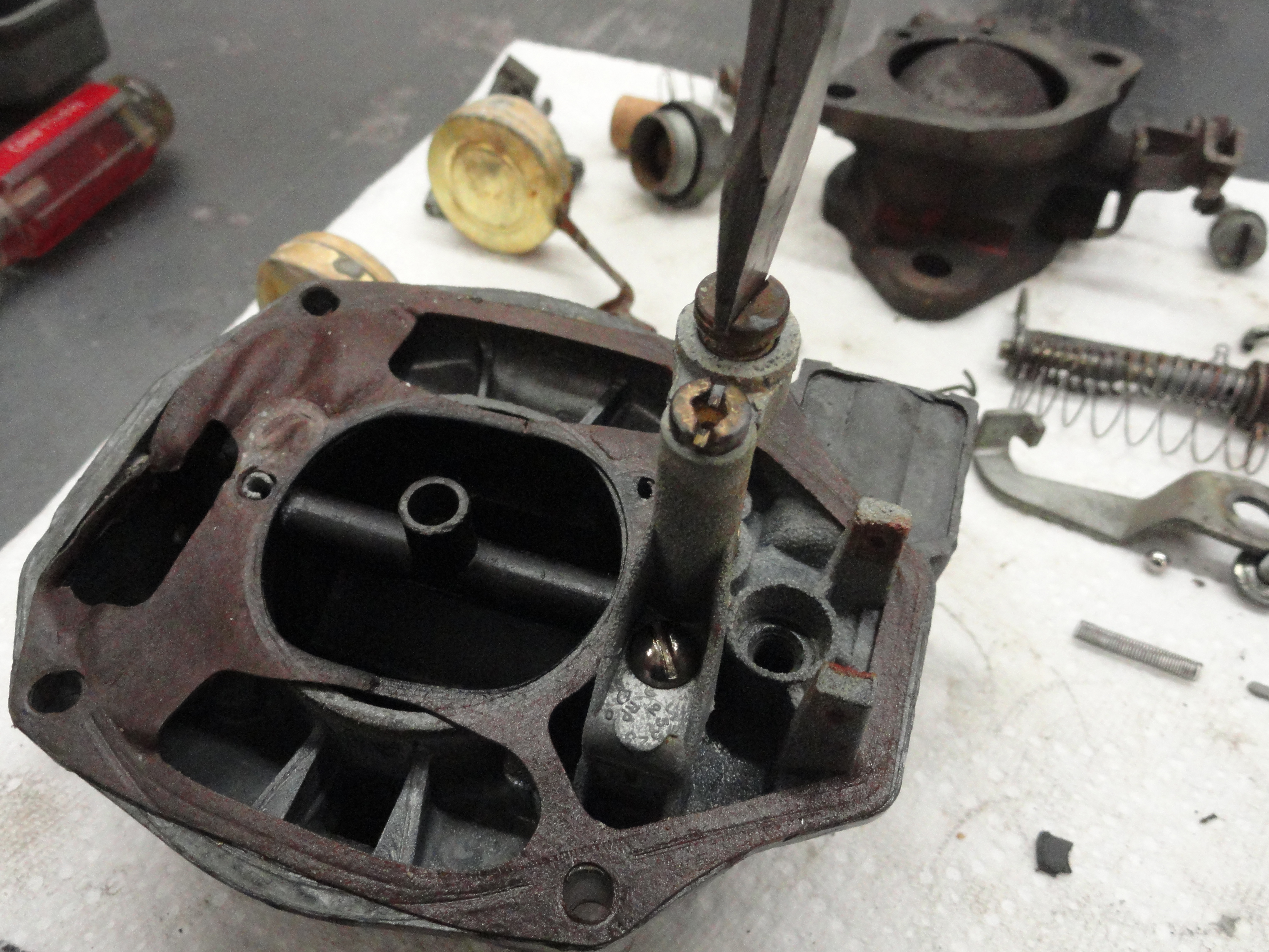
Start by removing the 1/2" pipe with the fittings on it. It knows it belongs there, so it will be kind of difficult to get off right now. In any case loosen the brass nuts completely. The Oil Pump is held in by a bolt with a locking nut. If the crankshaft is in the way, just put your balancer back on as far as you can by hand and turn the crank until you have access. By the way, the Oil Pump is the thing that has 4 slotted screws on top and that screen thingy sticking out! Get your wrench on the bolt and loosen it. You should easily be able to spin off both the bolt and the nut by hand after that. Remove the Bolt and Nut then wiggle the Oil Pump until your 1/2" pipe can drop right off, then pull out the Oil Pump.
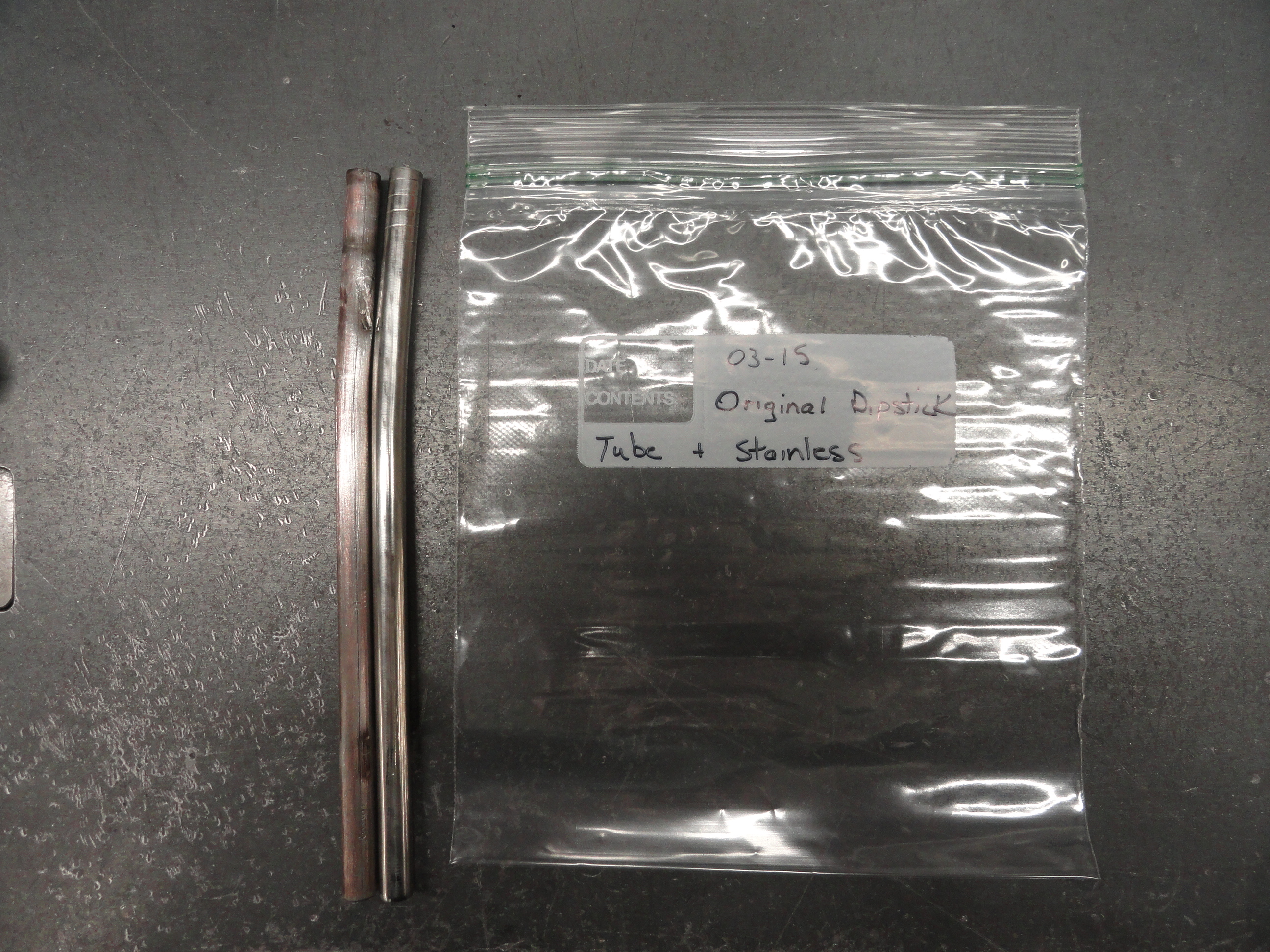
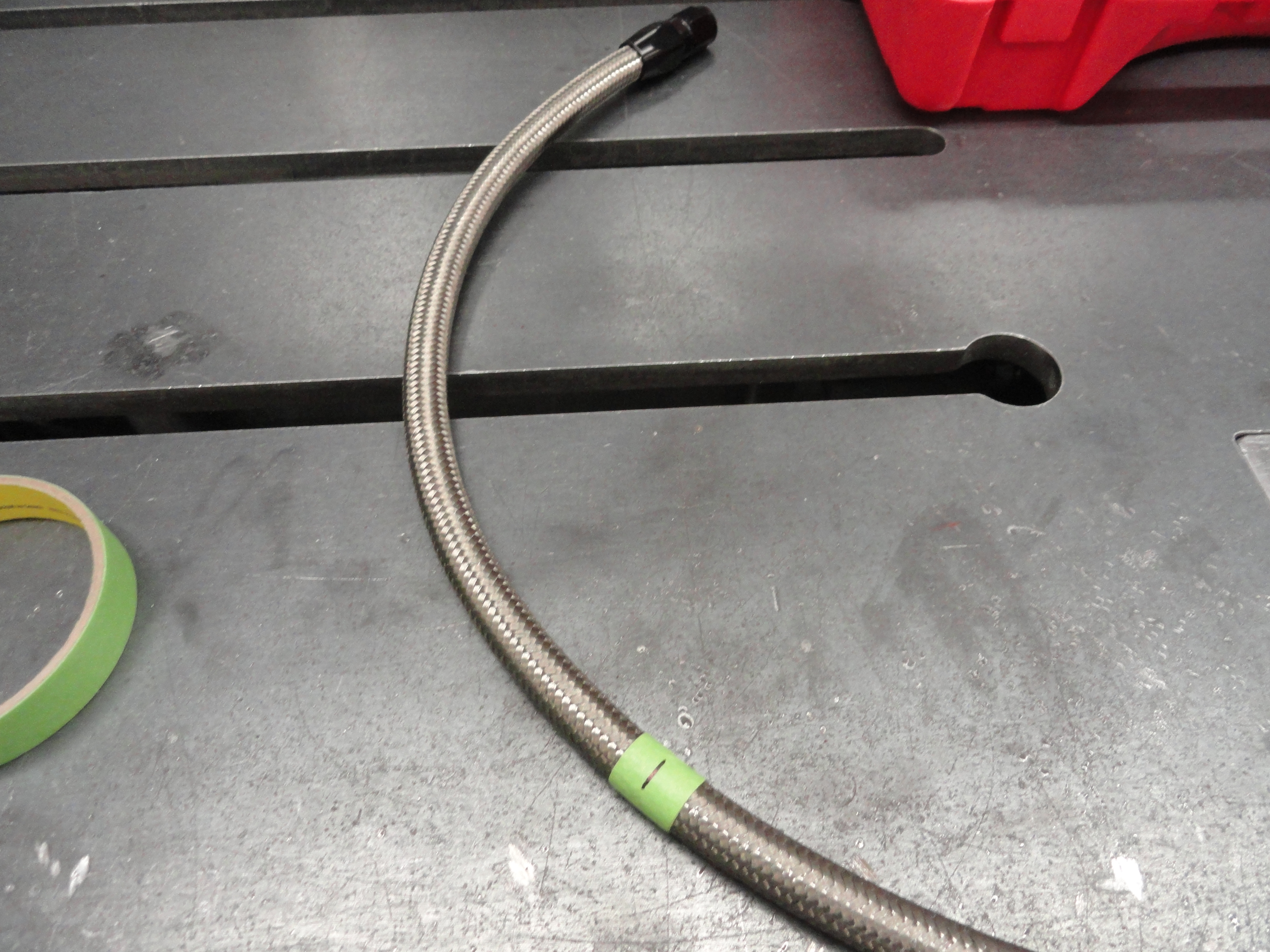
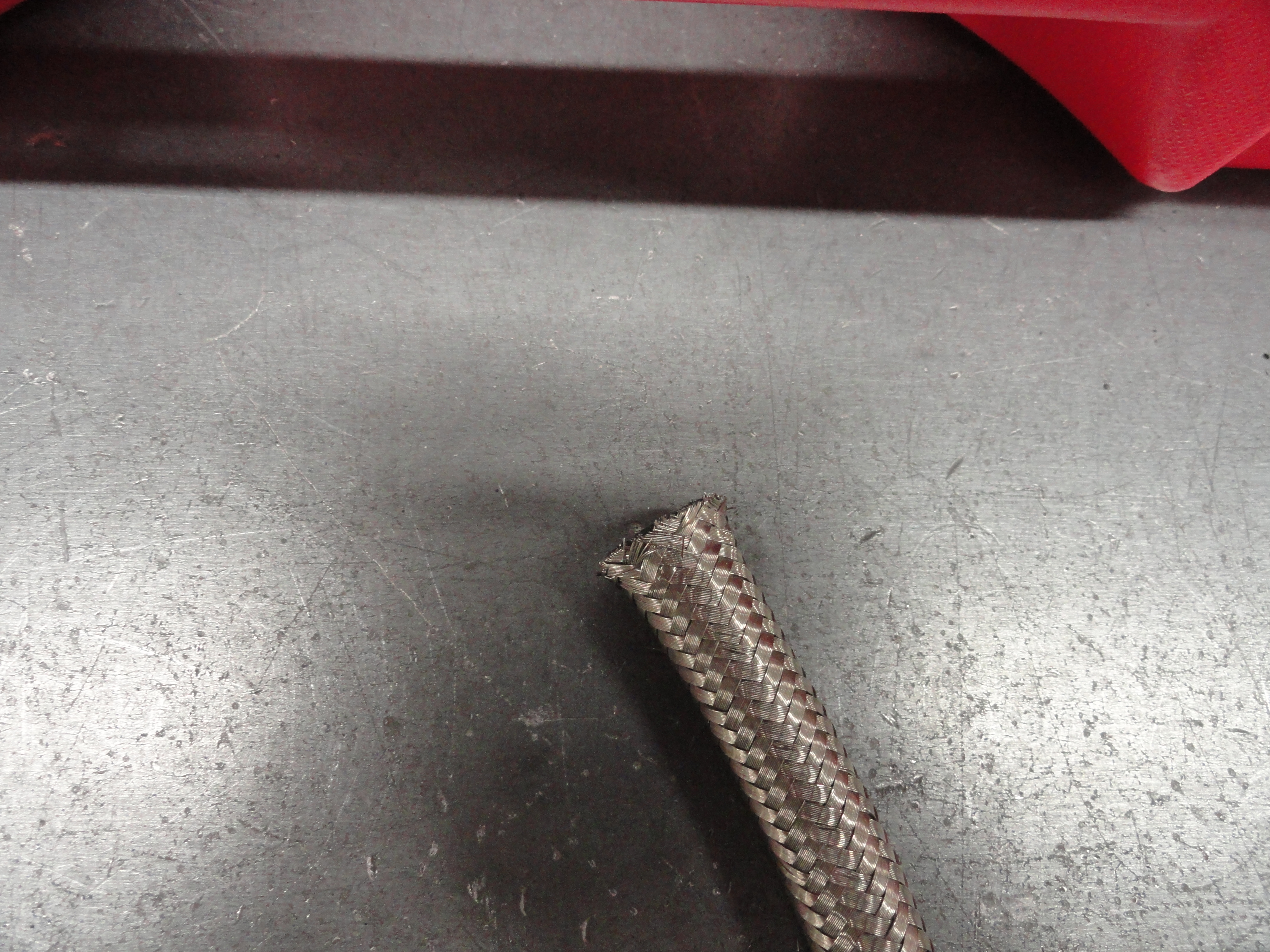
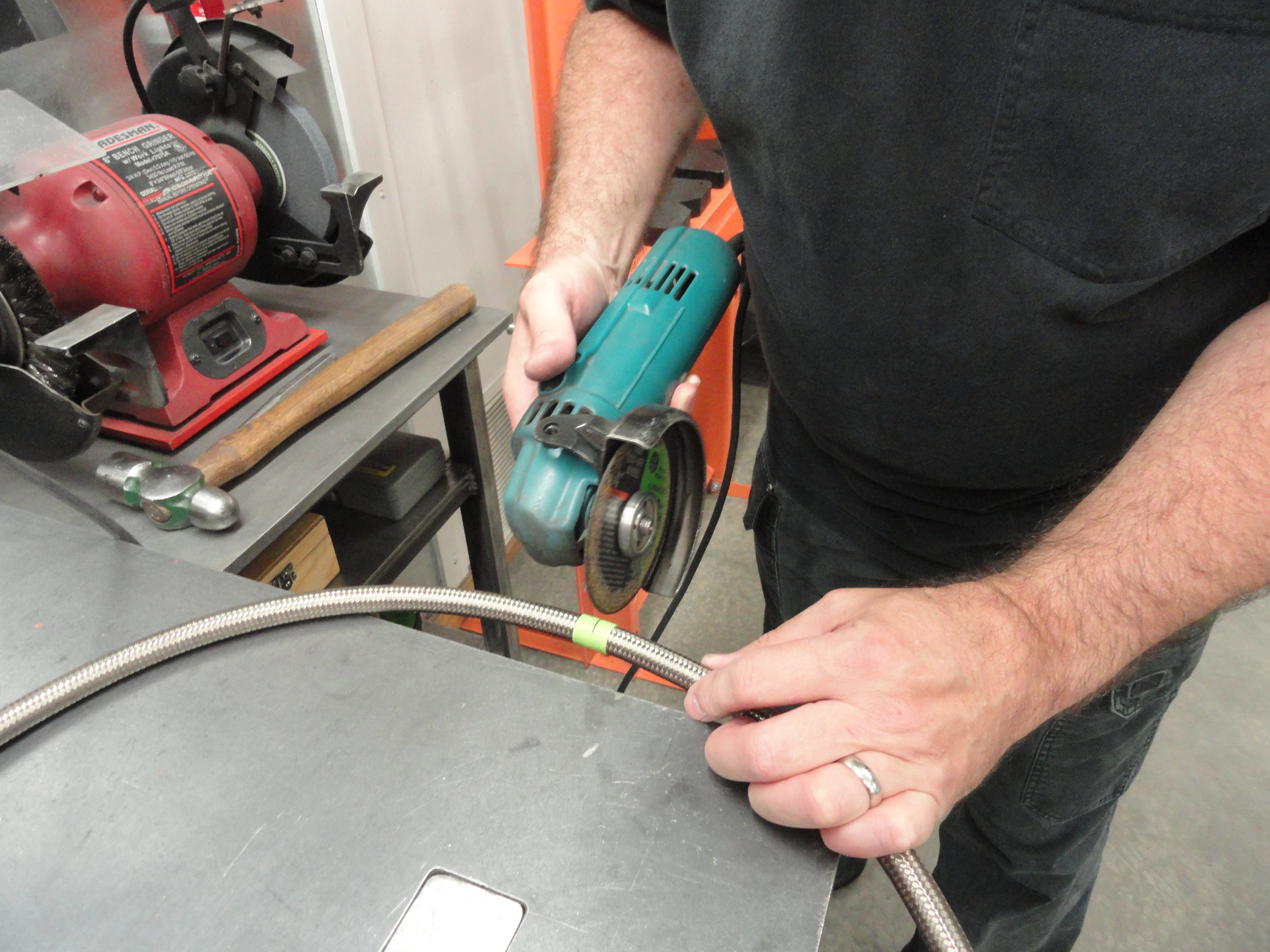
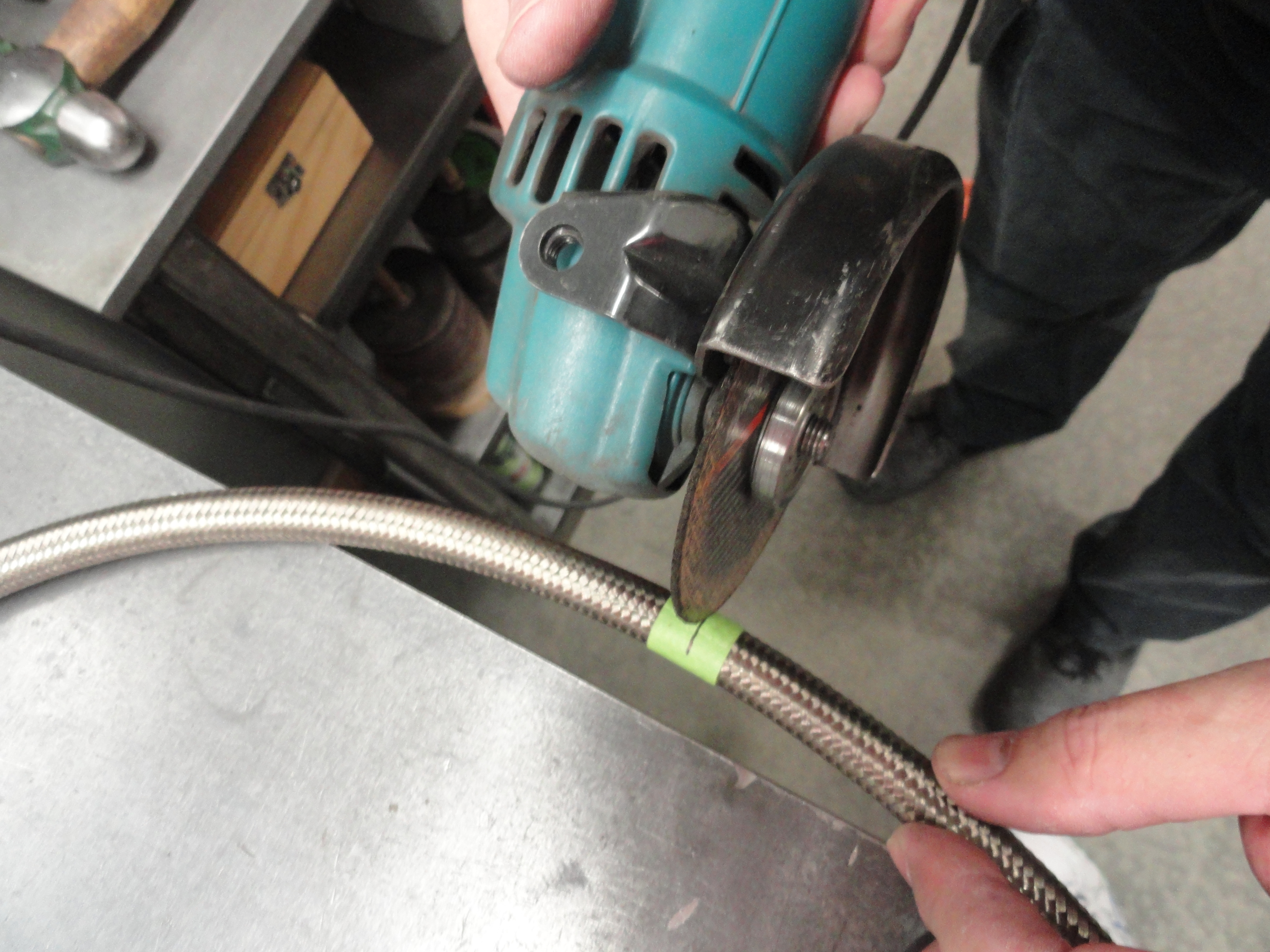
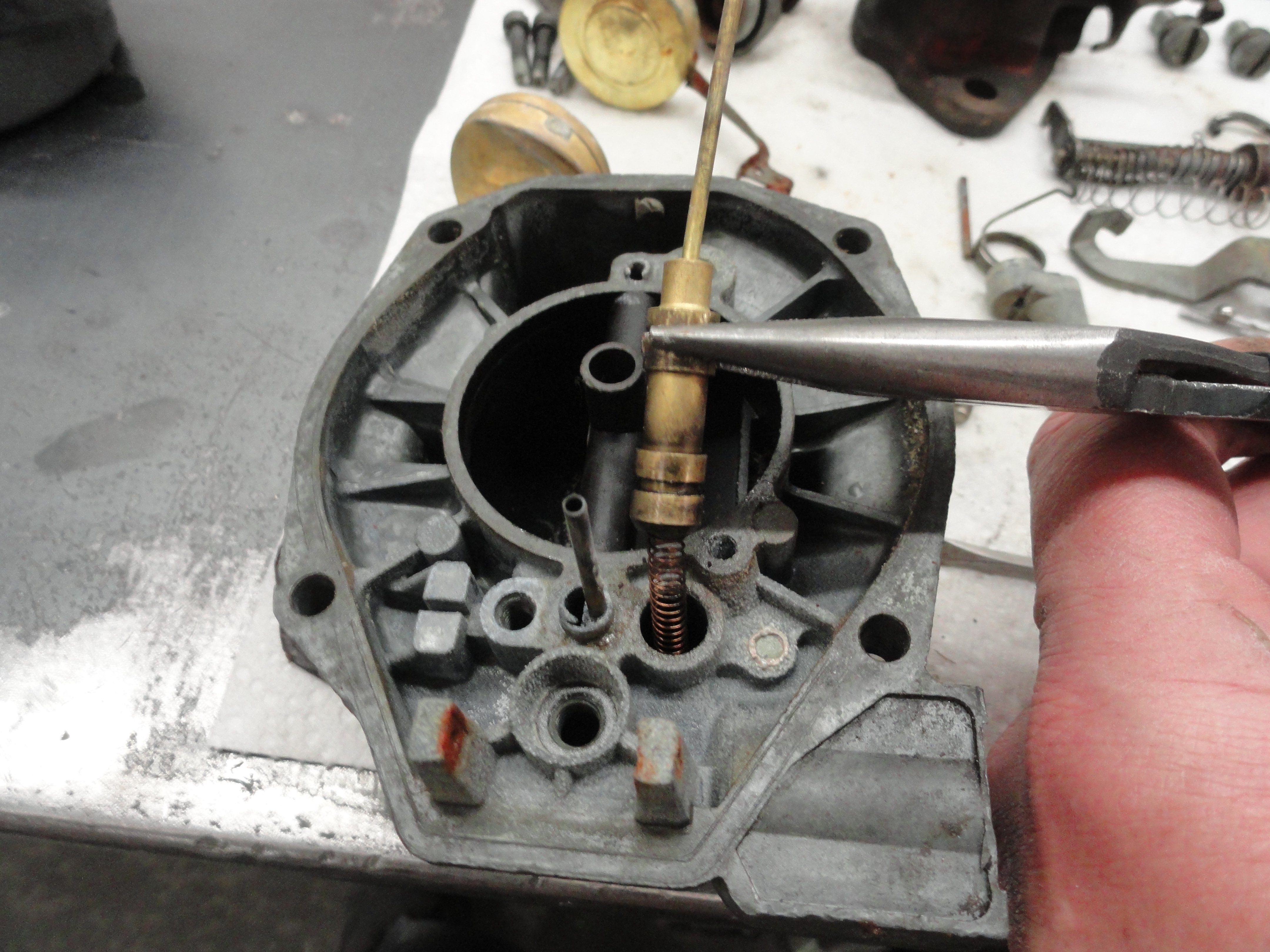
Remove the Dipstick Tube. You know, I have never found a good way to do that. You can't push anything down the hole in the engine block to push it because a 3/8" solid rod will just keep going into the tube. Pliers and a very light hand with lots of patience is really the only thing that seems to halfway work. BUT, all is not lost even if you ruin it. Be sure to take a good measurement, then get yourself a piece of 3/8" stainless steel fuel line. Happens to have the same wall thickness, same tight fit into the block and it looks cool!
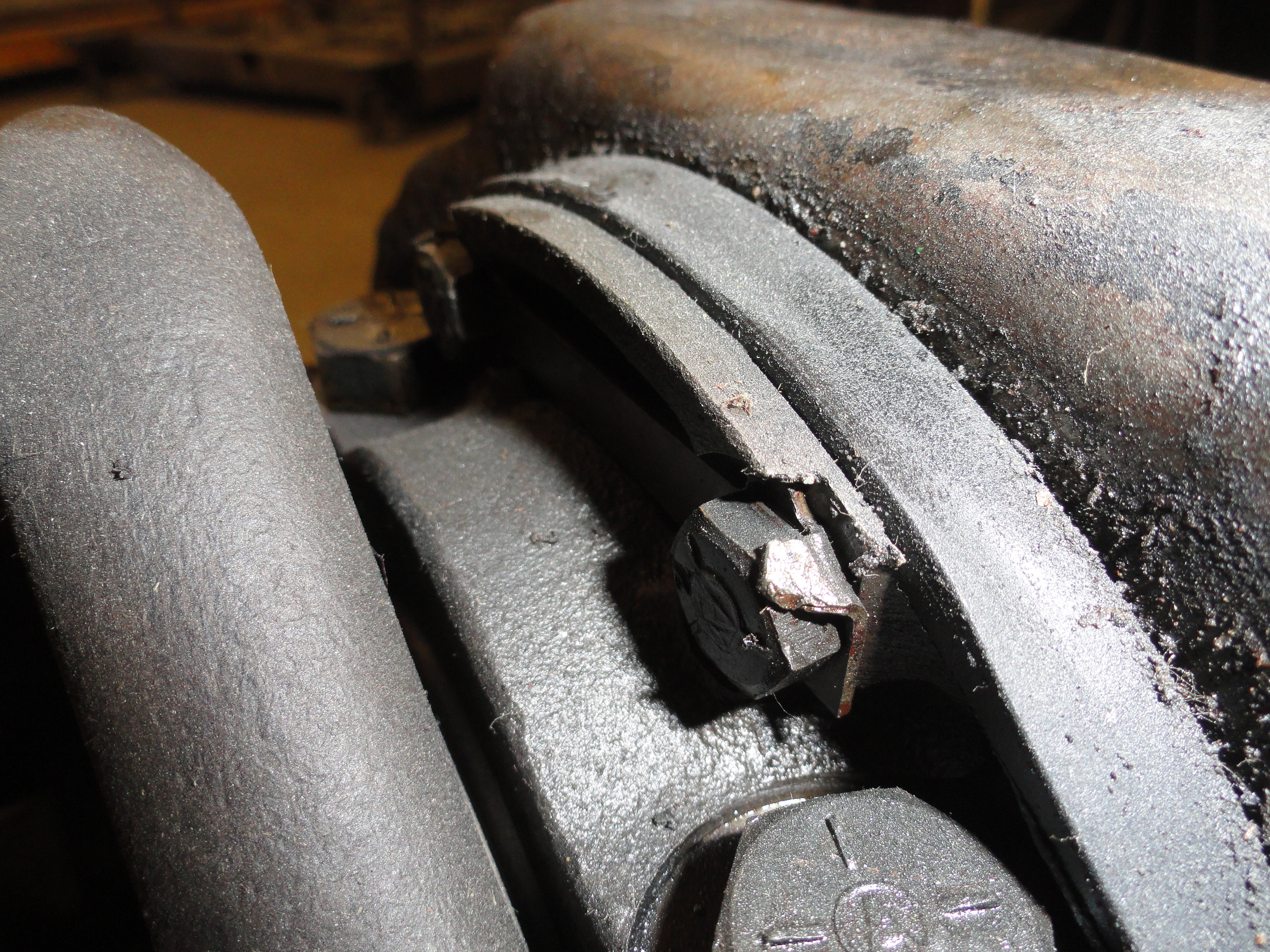

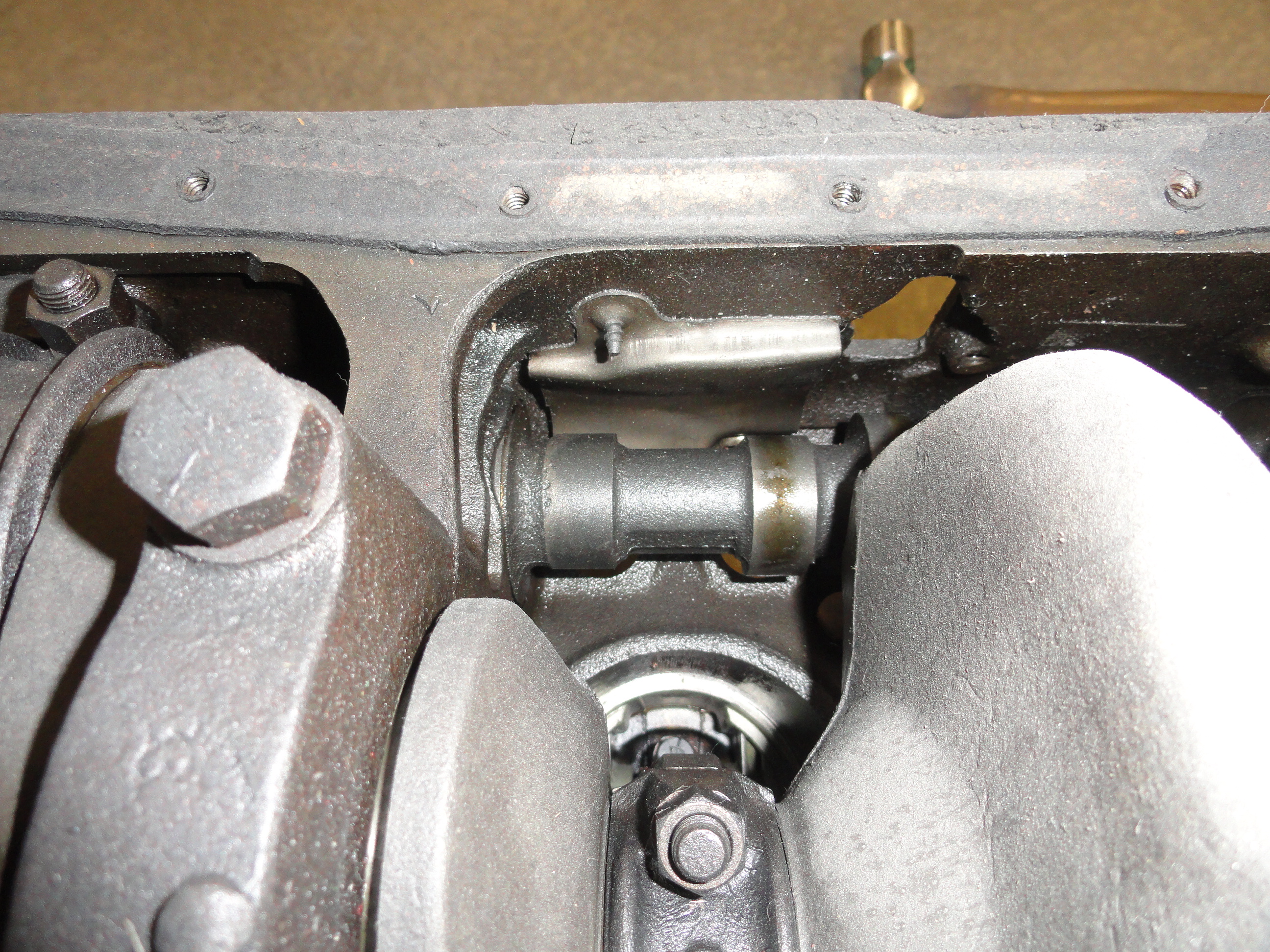
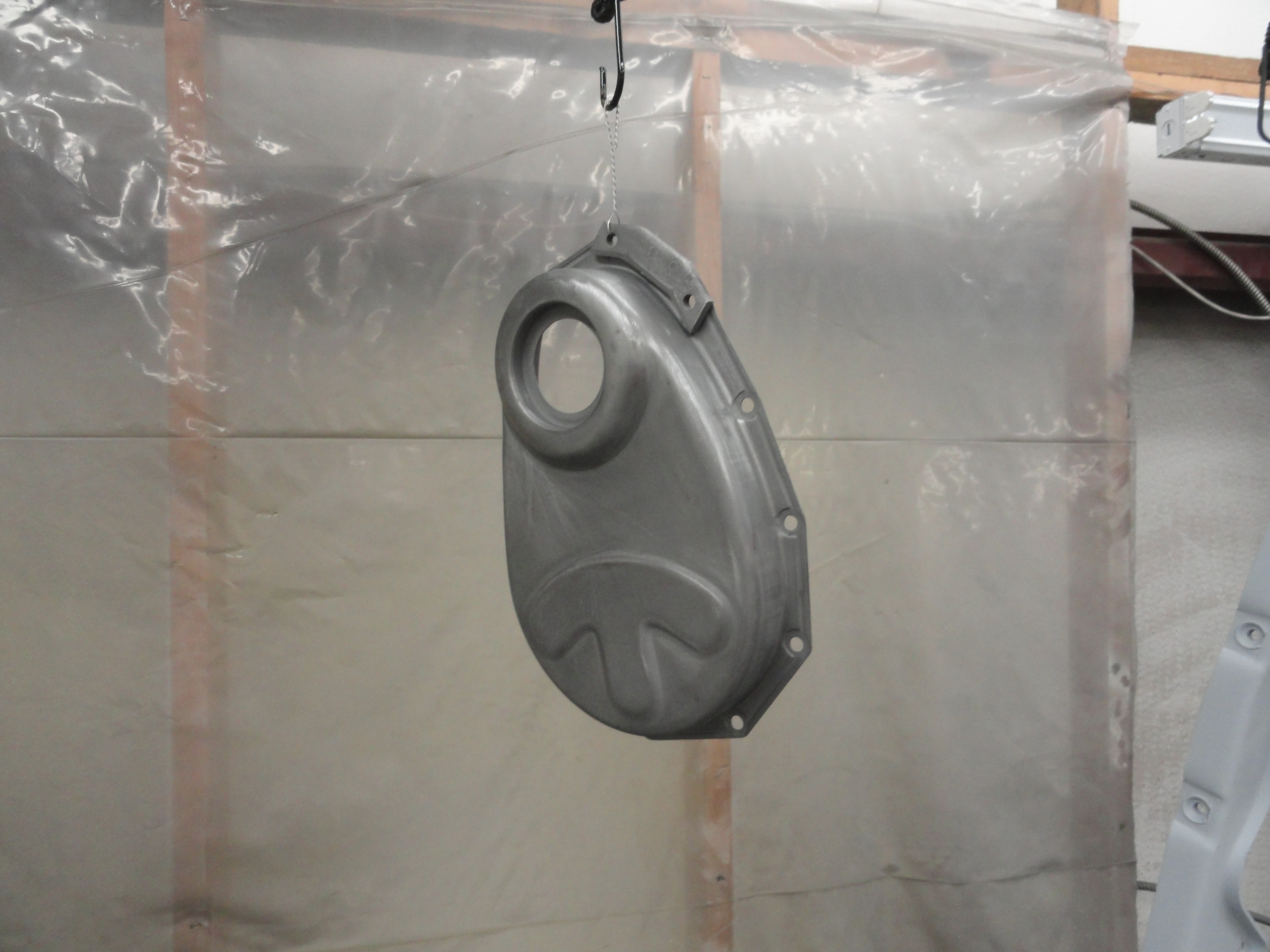
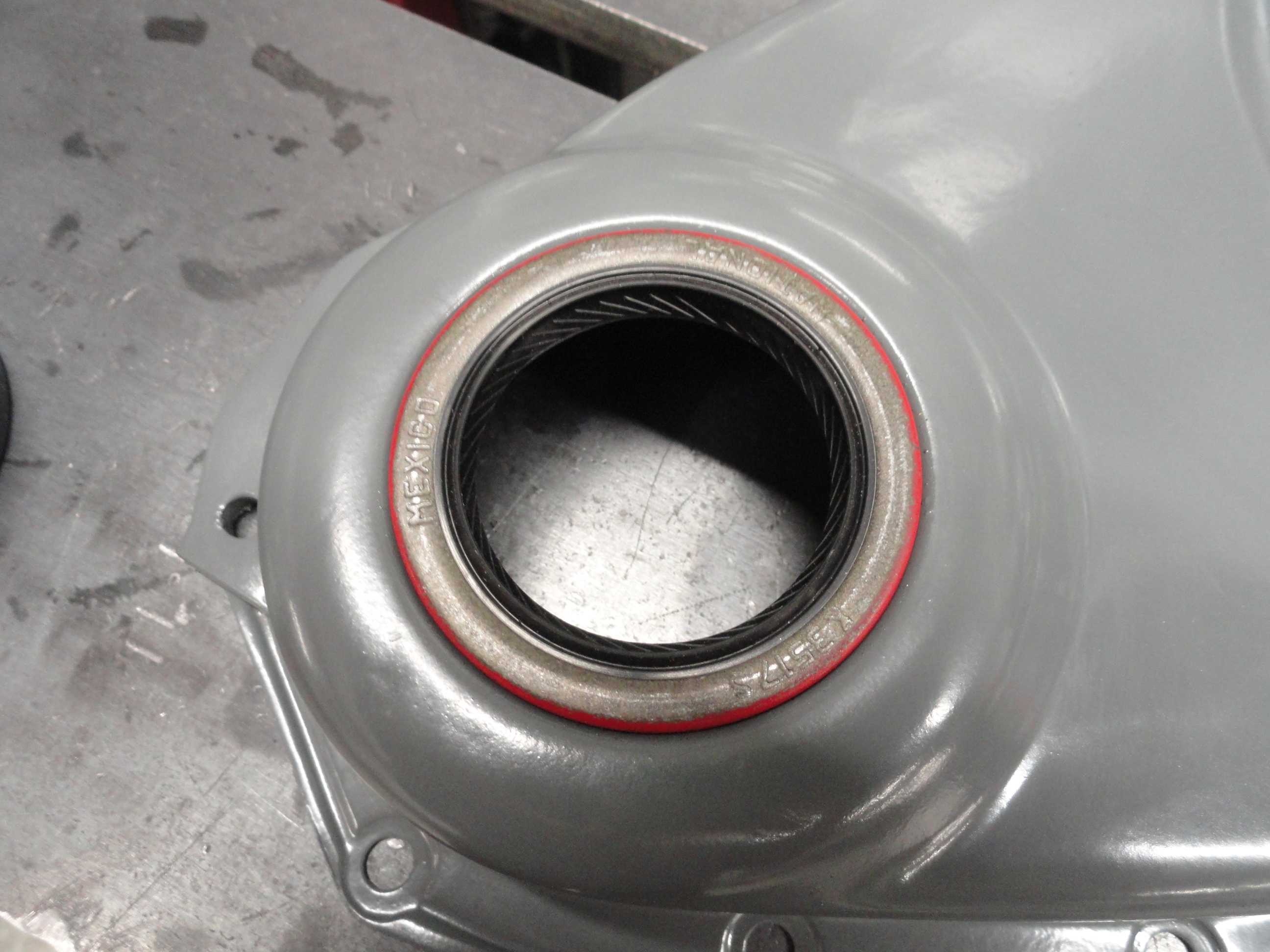
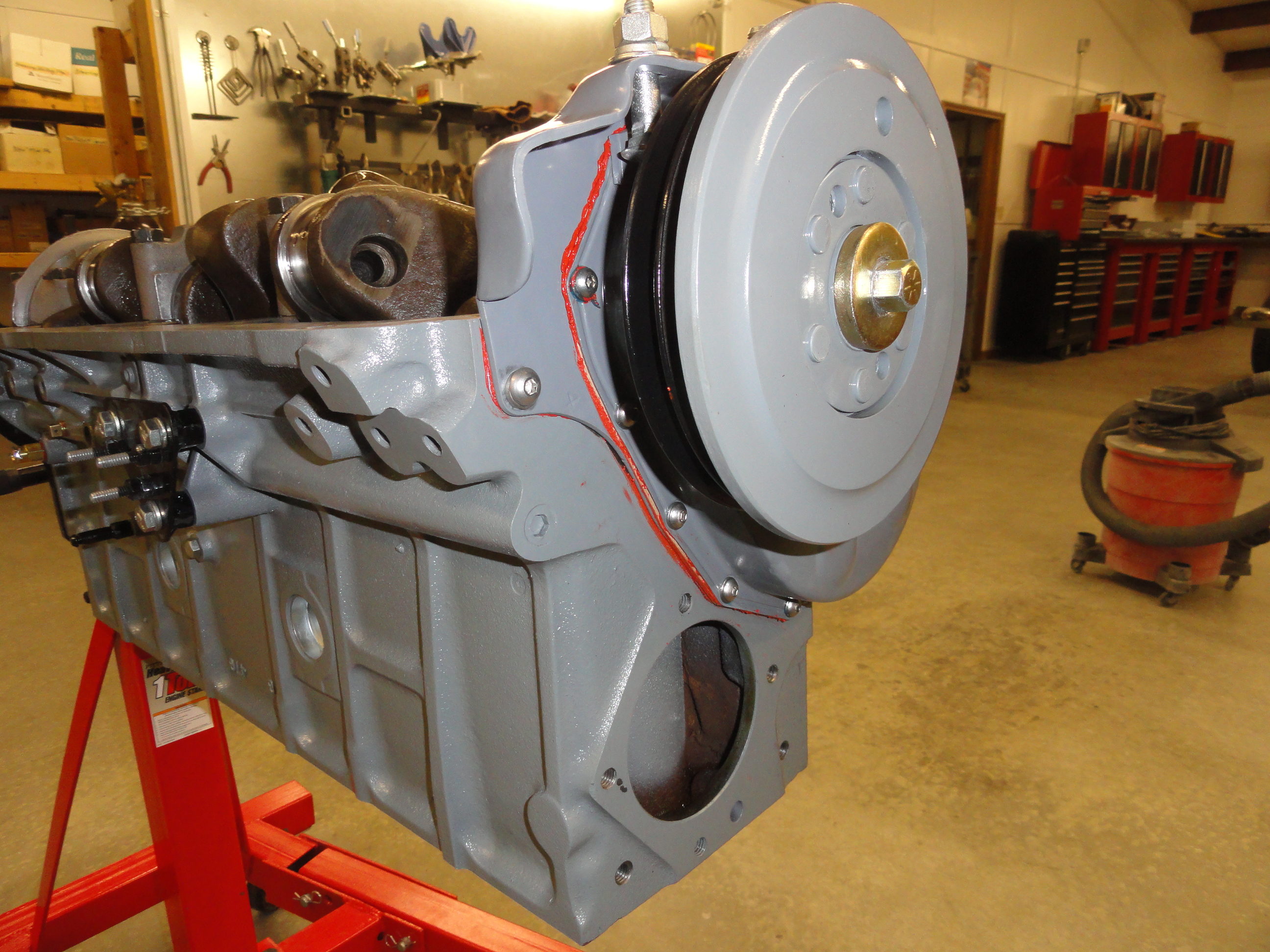
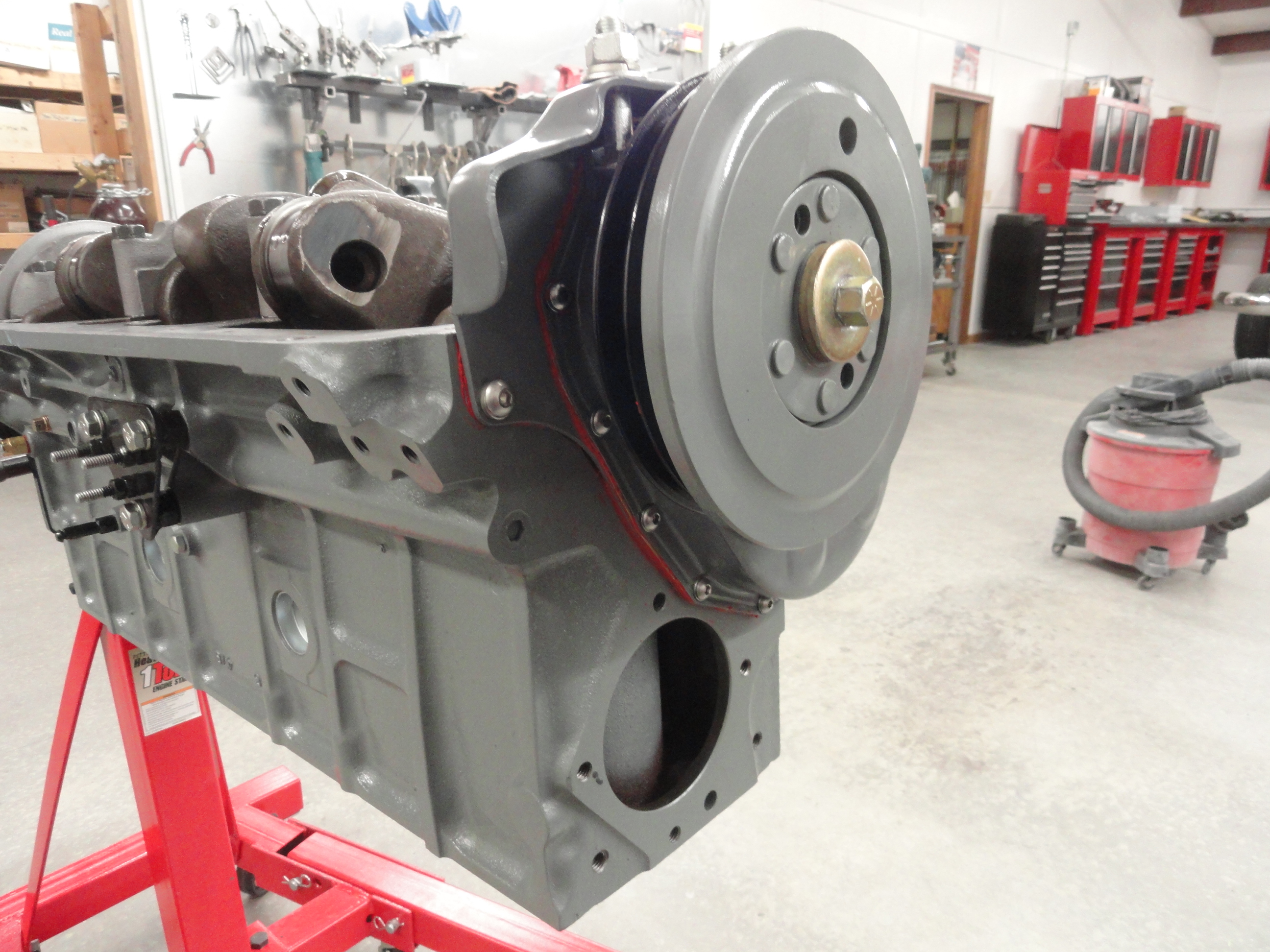
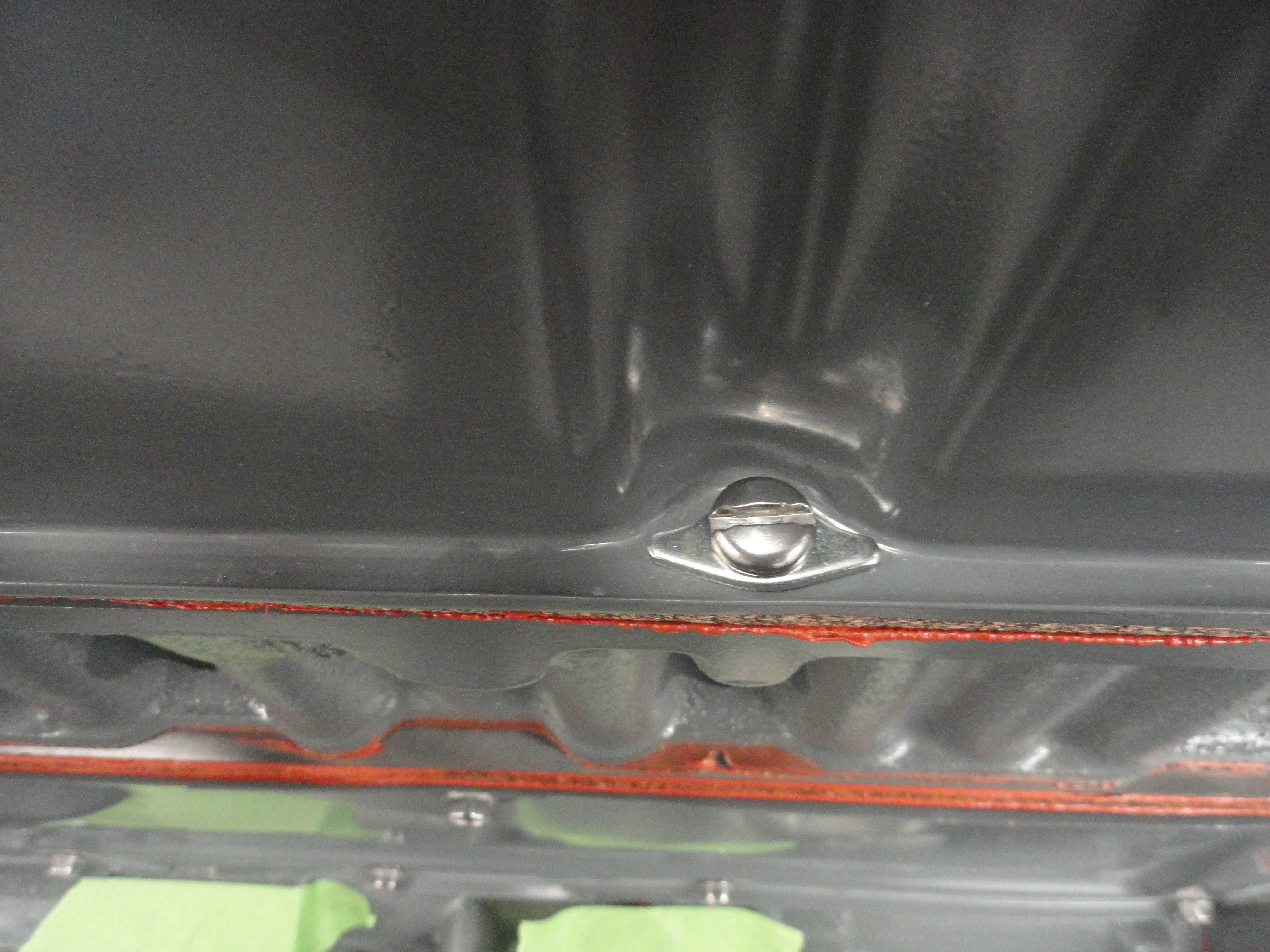
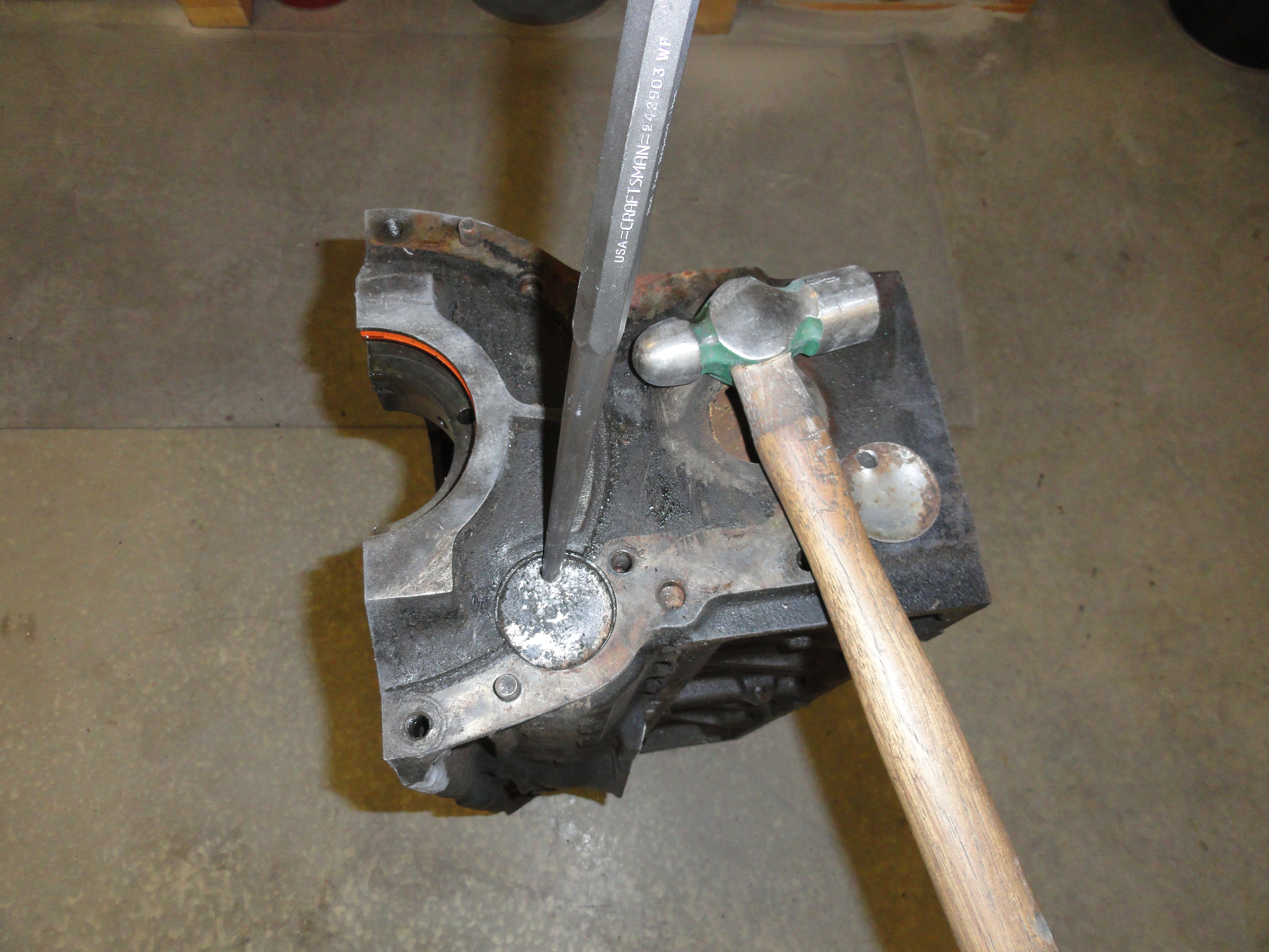
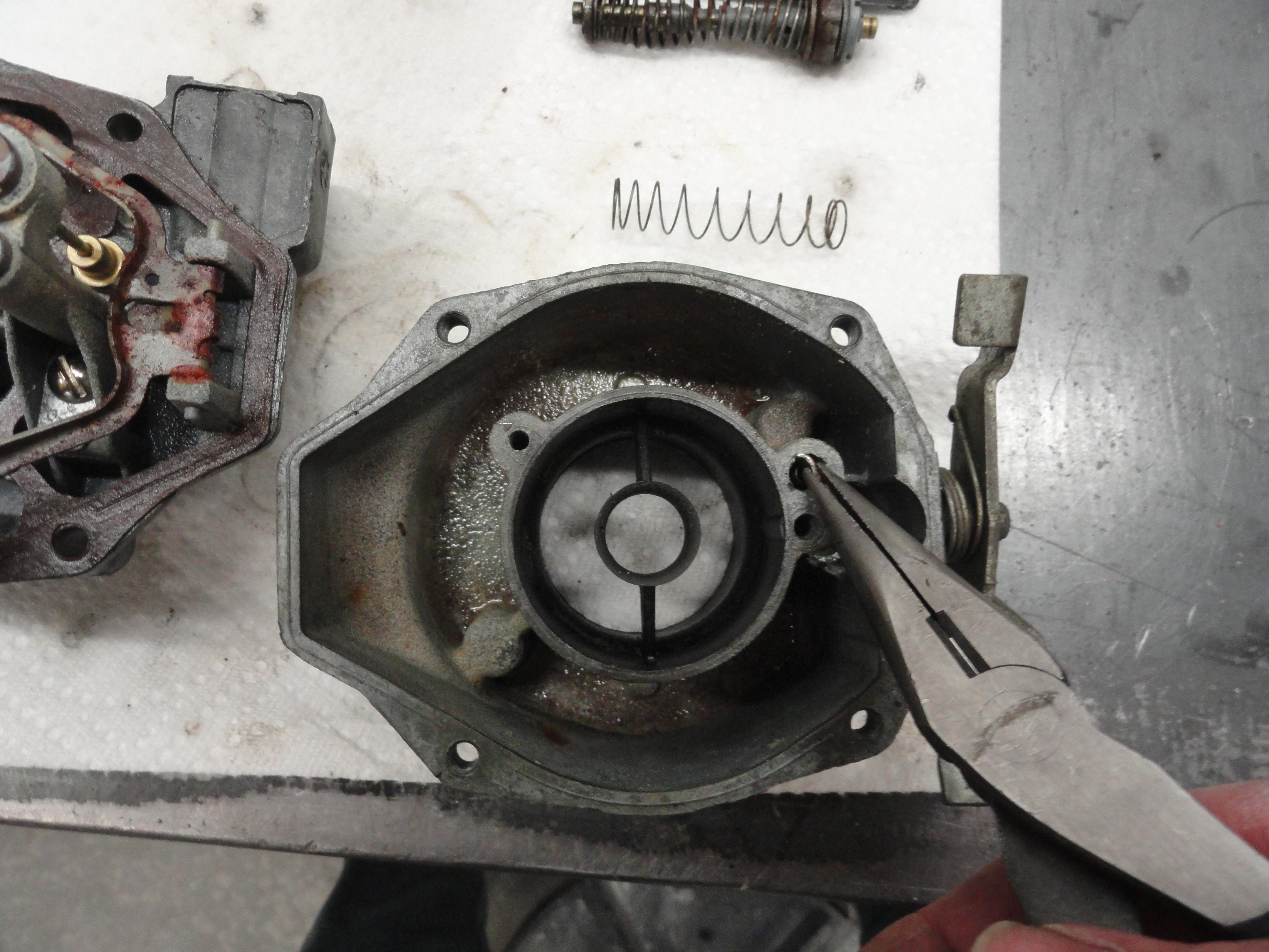
The Timing Gear Cover is held on by 8 short screws, and two longer screws that you can get to from the outside. Sadly, there are also two more hex head bolts on the inside as shown in the pic on the left. We want to preserve that bolt head retainer tin so very lightly tap on the tab with a screwdriver and small hammer. Take it in steps and it won't break as easily. Once you have both of the tabs bent slightly outward, Use your wrench to remove the bolts. Again, you may have to turn the crank a bit to get the bolts out. Remove all the bolts and the locking tin, clean everything thoroughly and put the hardware in a labeled ZipLock Bag. The Cover itself needs a little prep work before we move on. We need to remove the crankshaft seal that is embedded into the cover. Do not try to Gorilla this seal out of the hole with a big screwdriver hoping not to do damage to the cover! I set my bench Vise to about 4 inches open, then placed the hole in the cover over the open jaws, then with a punch lightly tapped all the way around until it came out. You want to preserve the tightness of this cover to seal connection. Once the seal is out, tape the inside area of the hole where the seal will be pushed back in and blast the cover. This will remove all of the gasket residue, old dirt and grime but preserve the tightness.
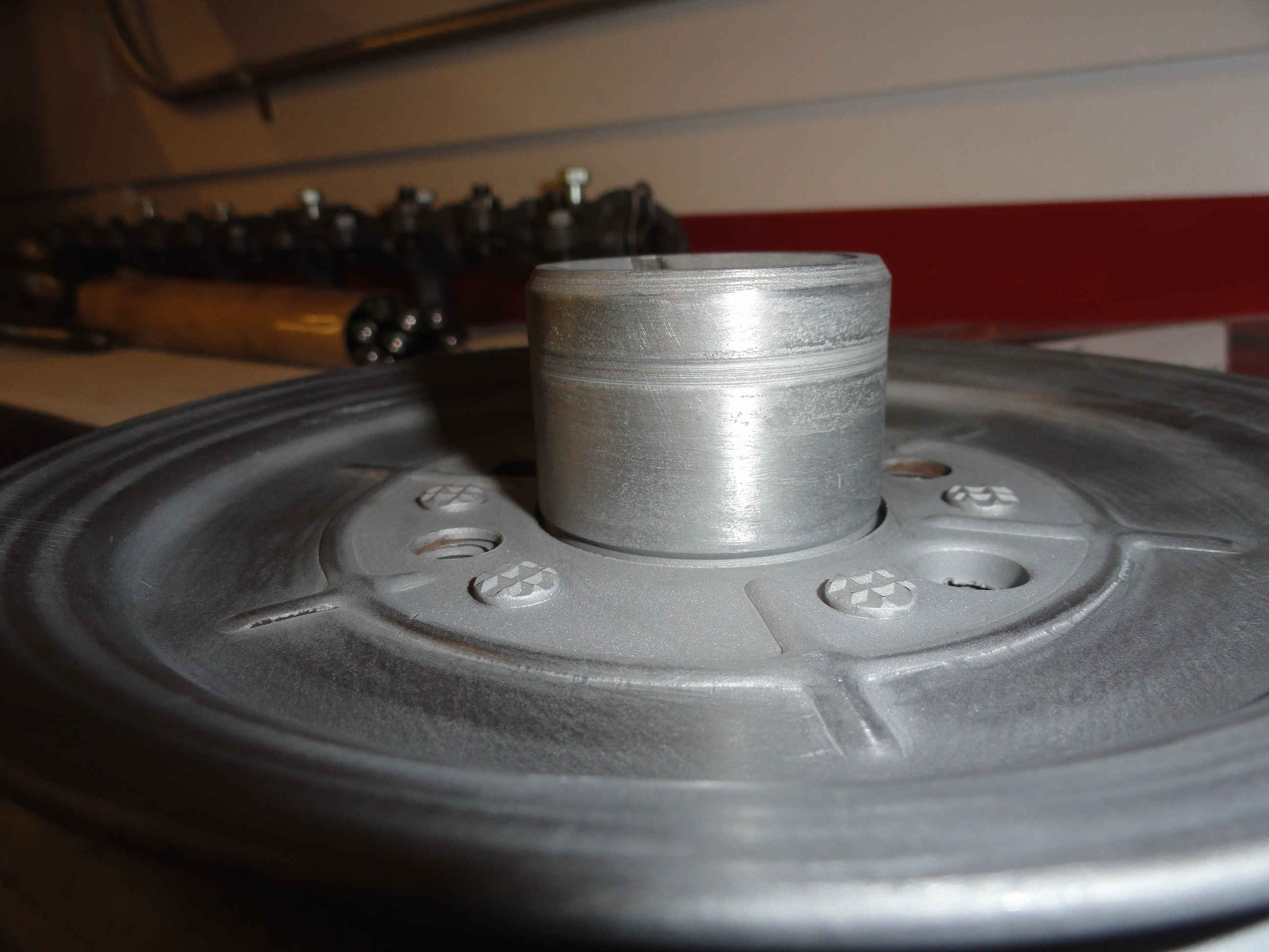
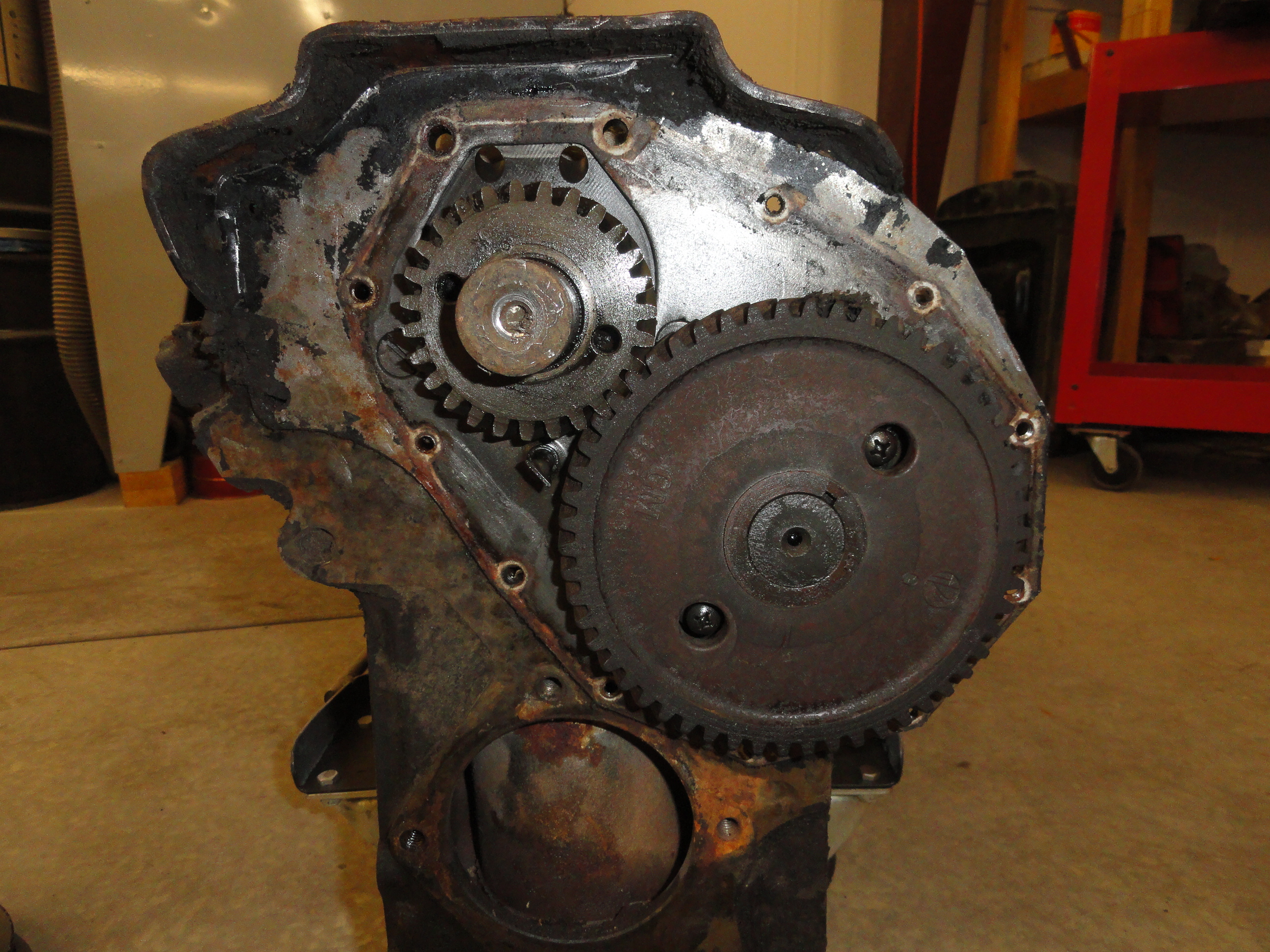
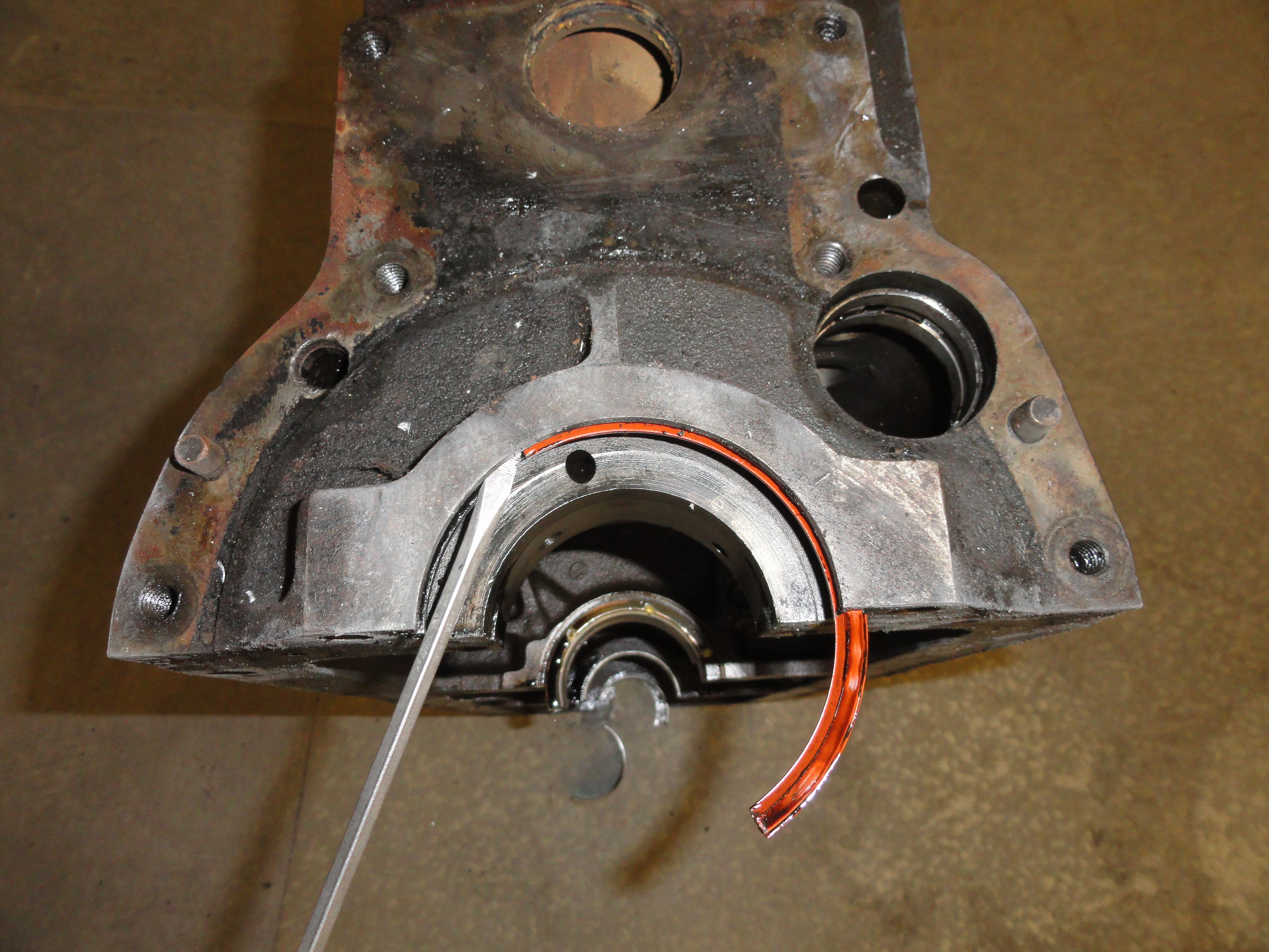
A few things to note here, the pic on the left shows the timing cover removed. No big deal, just wanted you to see what it looked like after
you did all that work! On the right is a picture of the removed Harmonic Balancer. This poor old engine was rode hard and put away wet. Wet
is a bad thing and you can see the pitting that has occurred where the Timing Cover seal rides on it. The grooves are very IFFY at this point
and I will probably opt to put a stainless steel sleeve over the shaft just to be sure we have no front seal leakage. Our ZipLock Bag system is
beginning to look impressive and once we have all the tin completely re-worked, we will be able to really see the progress. The tin has
turned out to be very time consuming. Lots of dents, holes, and unacceptable anomalies in these pieces. If you want something perfect, you
just have to put in the time. It pays to do this in steps and do not move on to the next step until the other one is finished. Too many
steps being juggled can lead to missing something important.

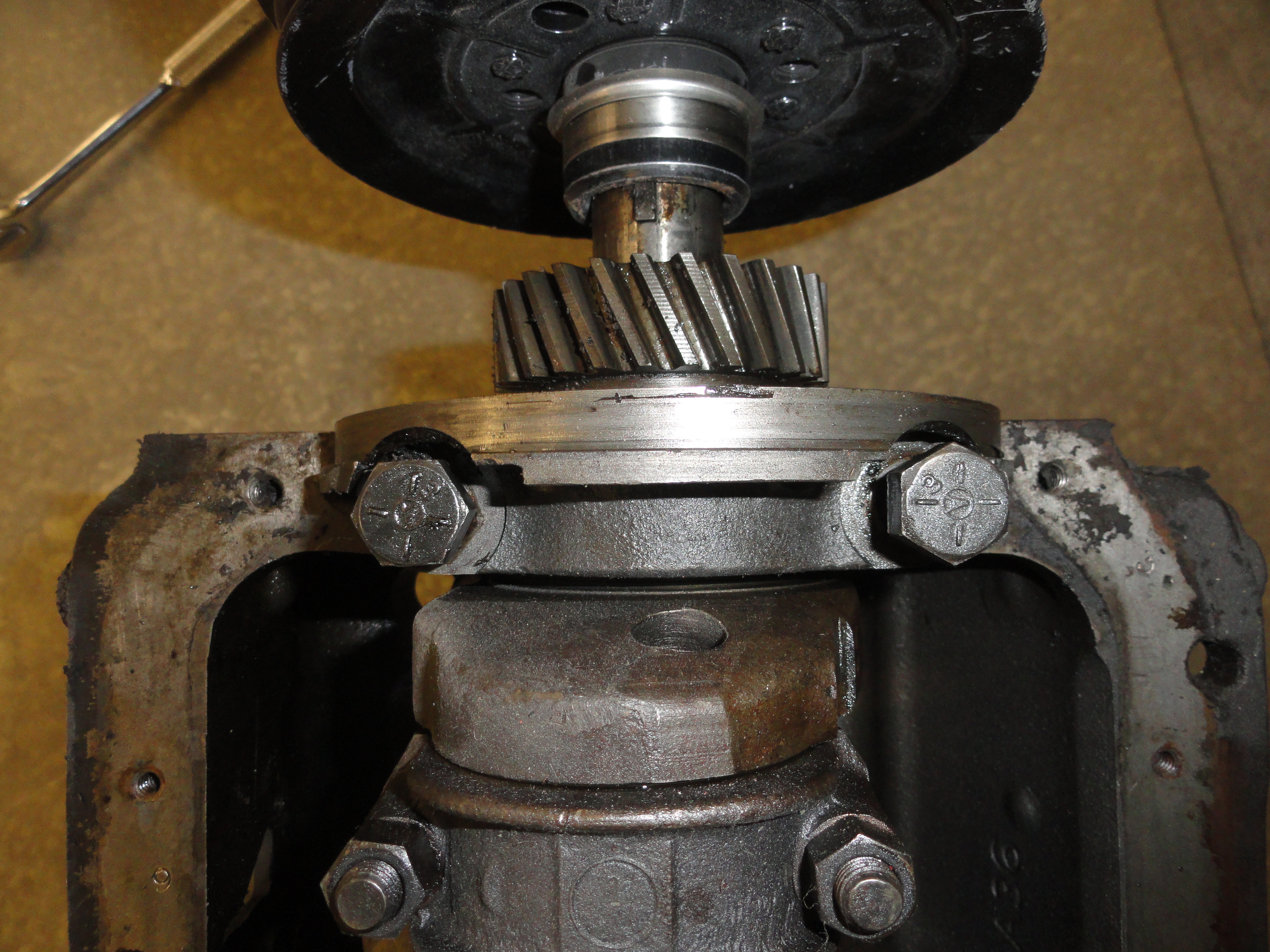
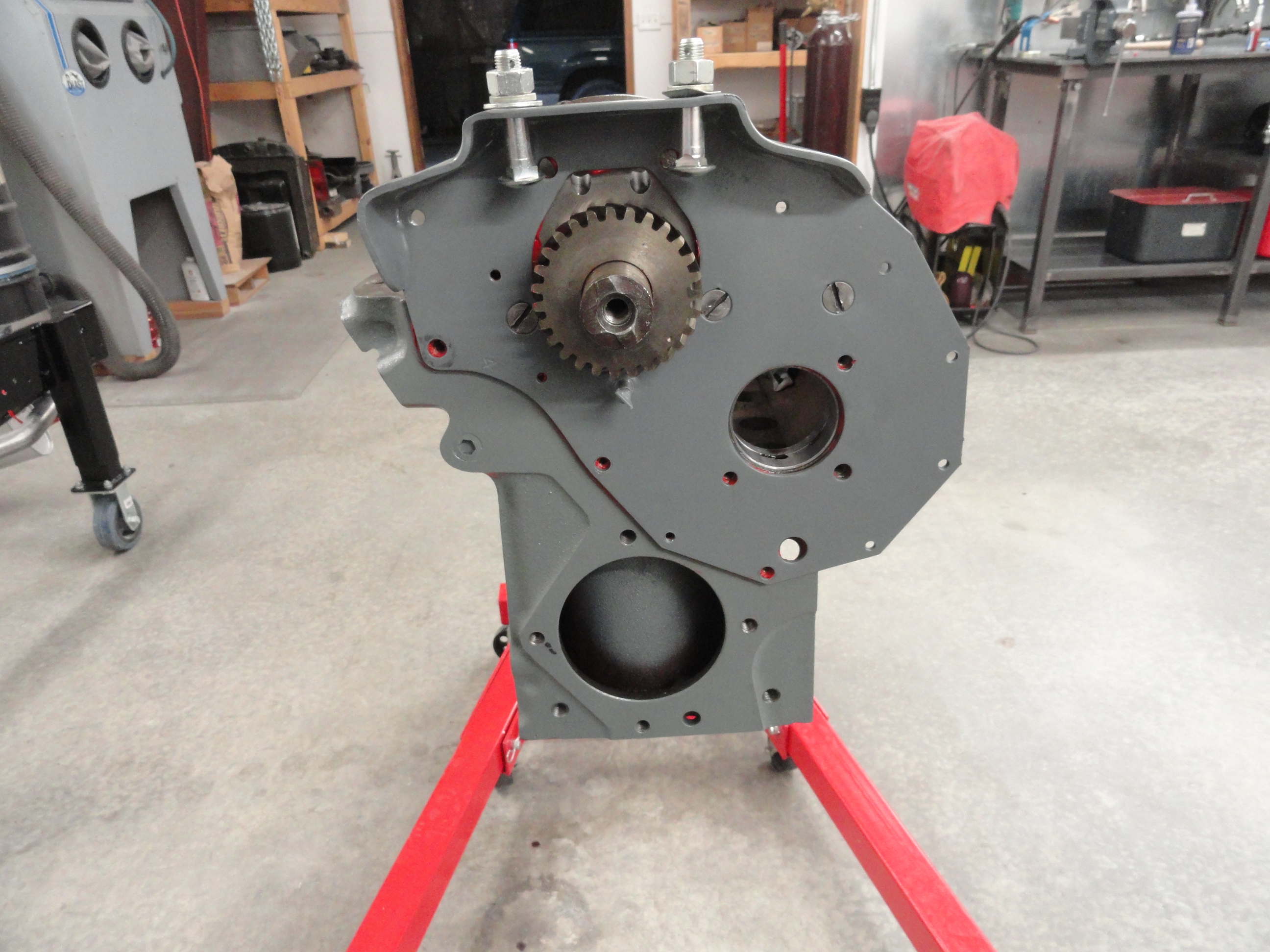
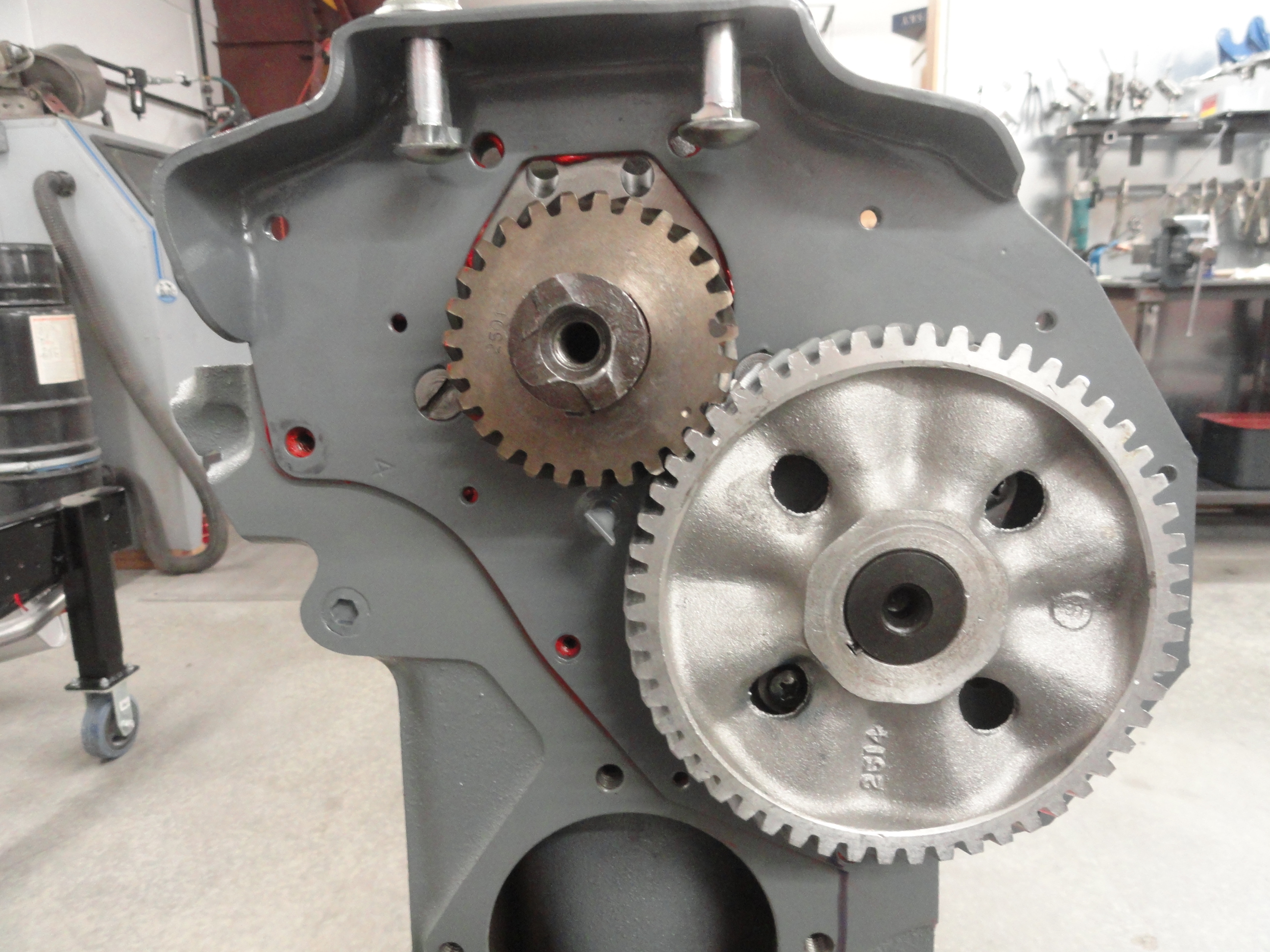
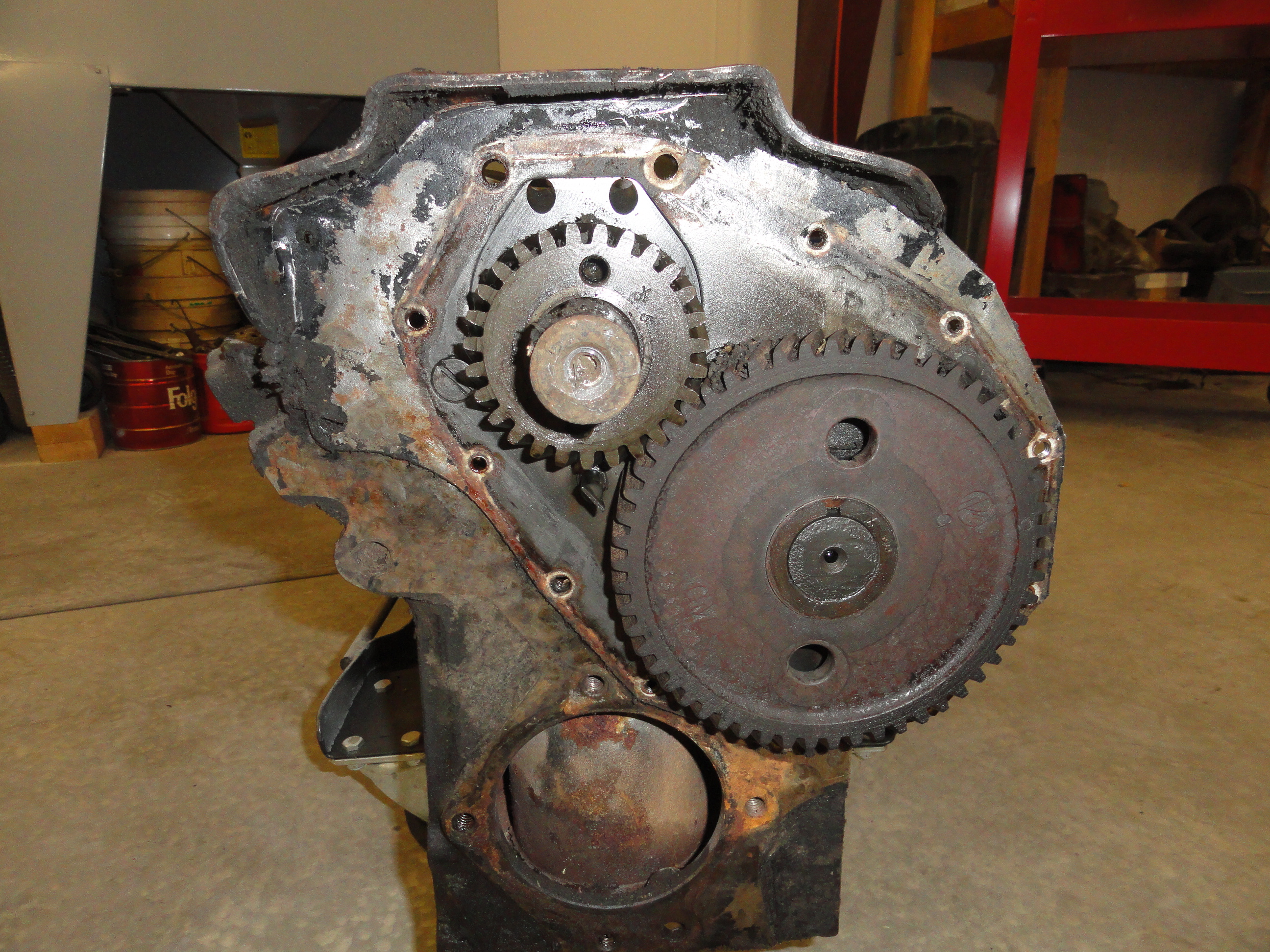
The camshaft will be replaced along with the cam's gear and all of the cam bearings. But when you pull it out, you will notice all of the journals it has to go through to get it in or out. Remember this because when installing it, it will be imperative that you take your time and be very careful not to ruin the new bearings.
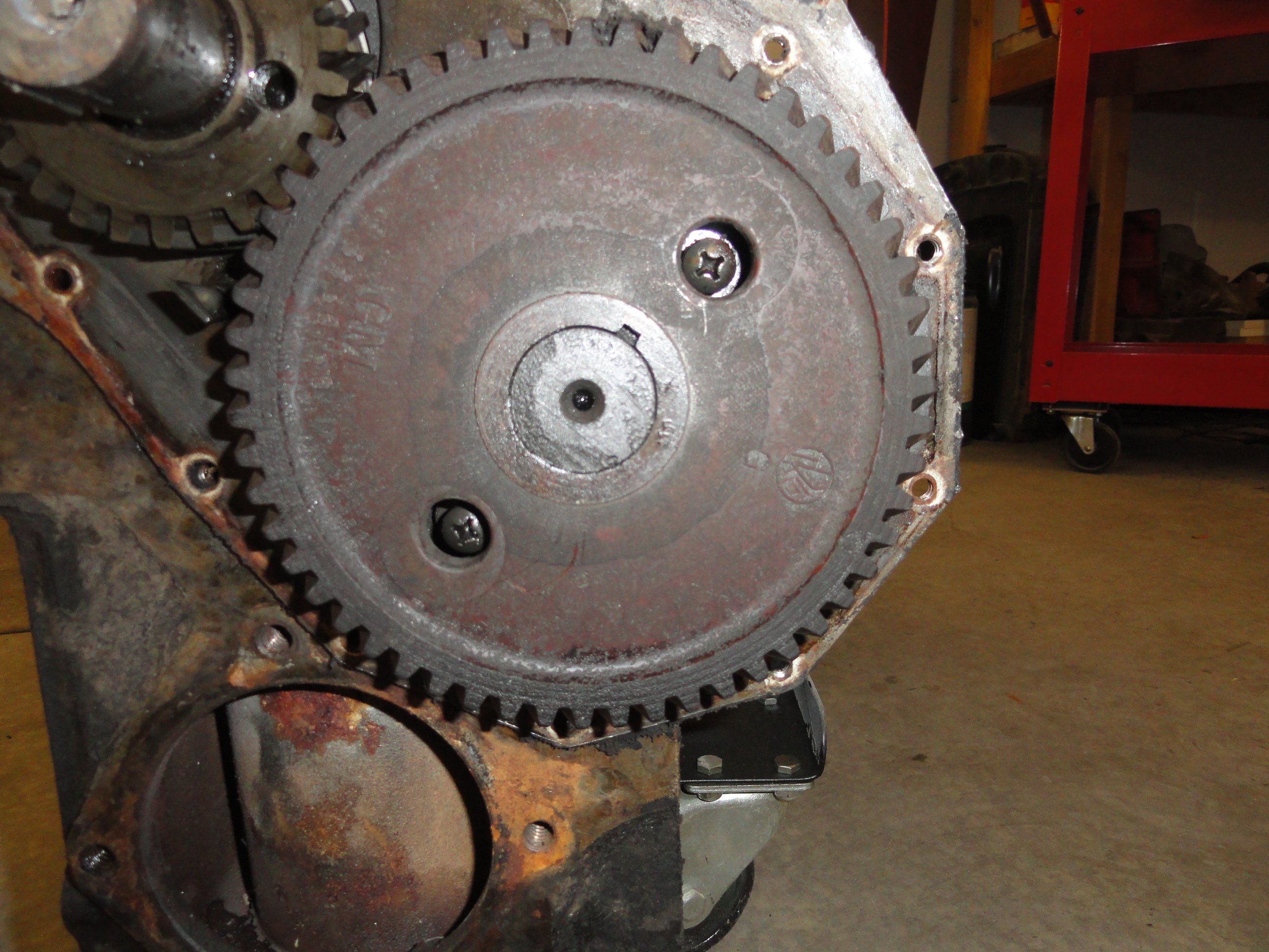
To remove the cam, rotate the crank until you see two Phillips Head screws through the gear as shown on the left. These are the screws for the camshaft's retainer. Remove the screws and then very carefully pull the cam (with the gear still on it) straight out. Clean the screws and put them in a separate ZipLock Bag.

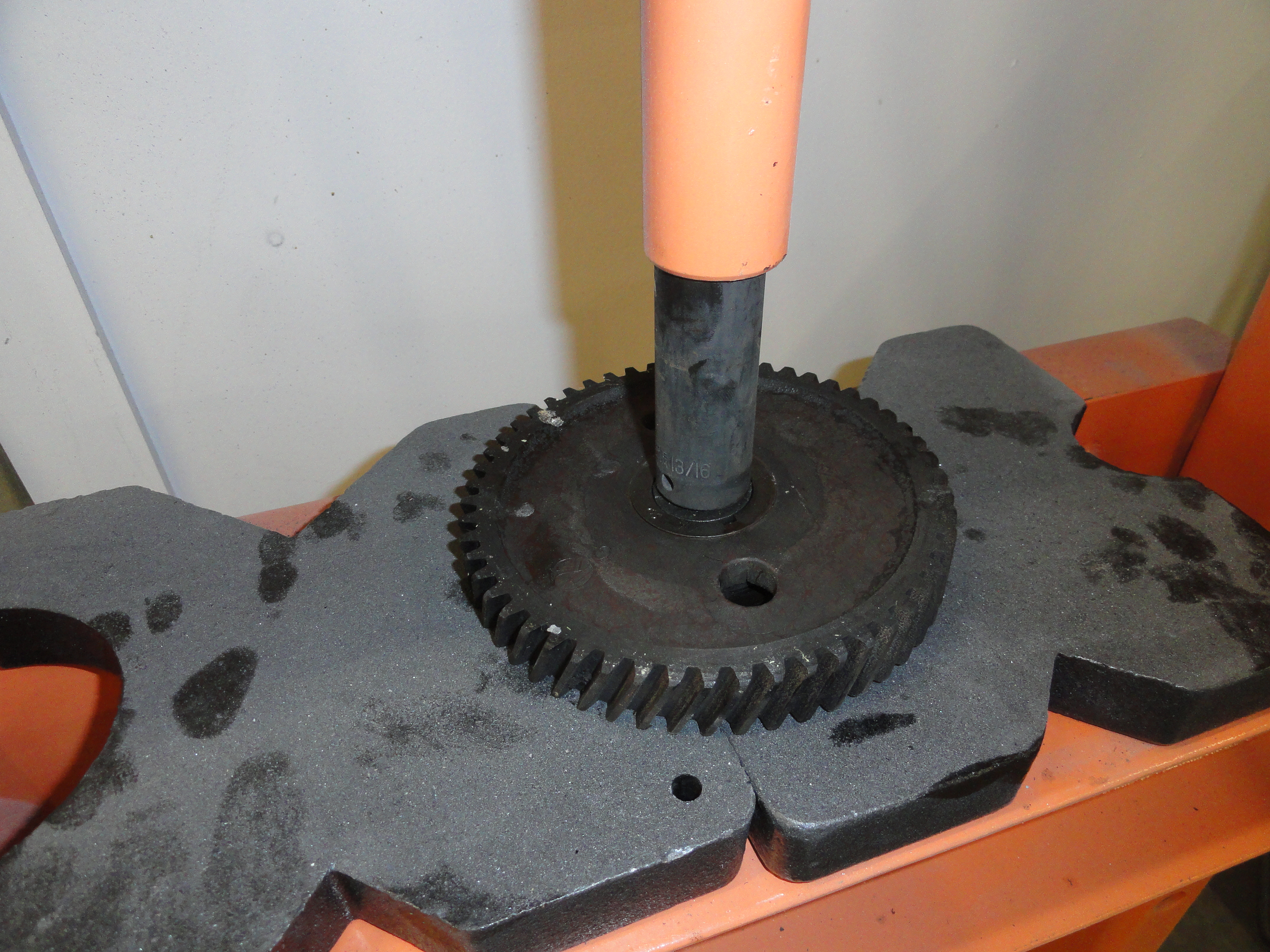
Even though we won't be using the old Cam or Gear, we need to retrieve the Thrust Plate. That's the plate that you removed the two screws from to release the cam to get it out. To get to this important plate we need to press out the gear. I have found it very useful to have a 20 Ton Shop Press in the shop for removal of U-Joints and other things that are press fit. Although not used everyday, it's awful nice when something like this comes along. You want to also retrieve the crescent shaped key that helps keep it in straight. I just pryed it out with a screwdriver. Don't forget to save it for when you are ready to press the new gear on.


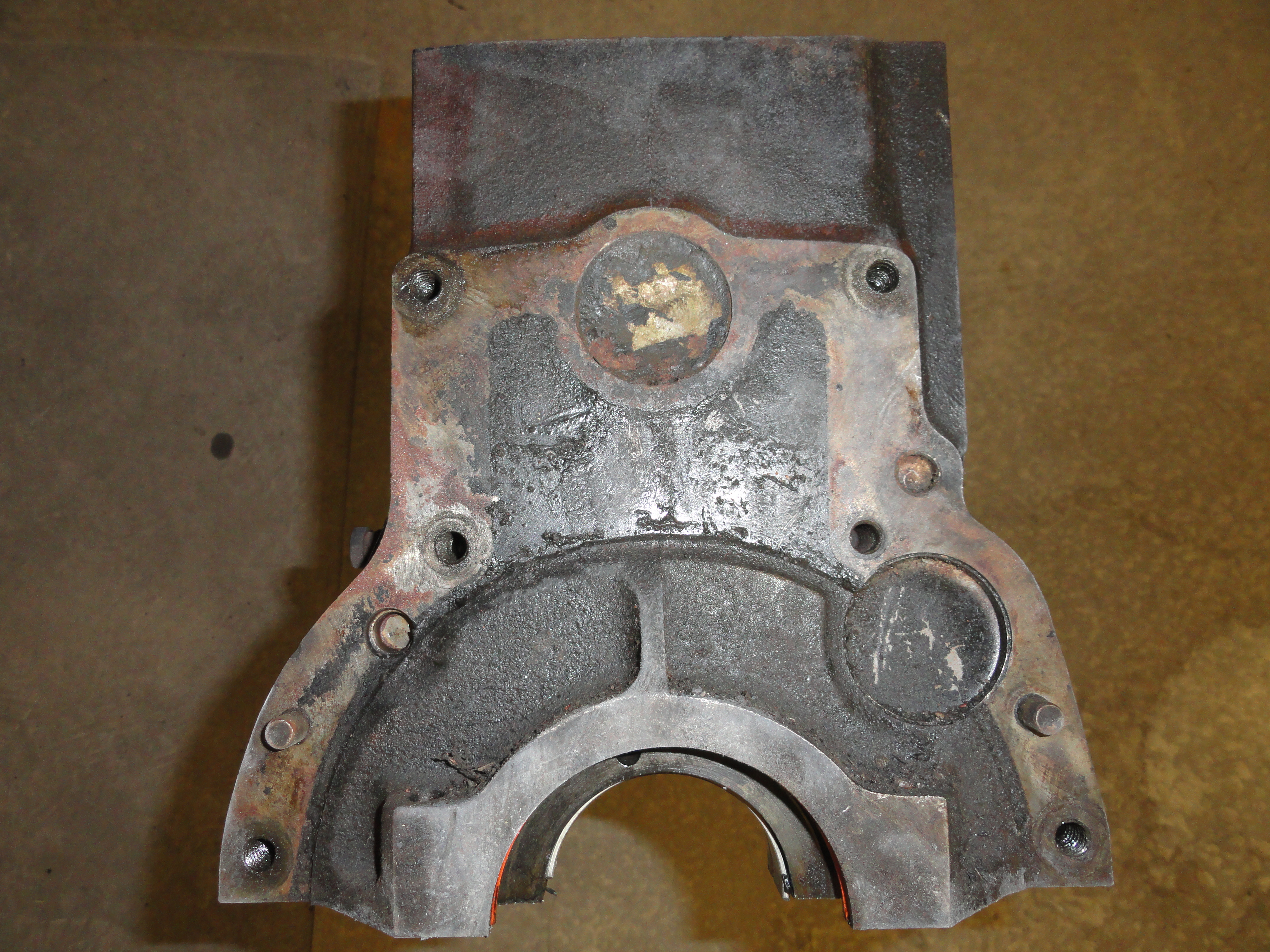
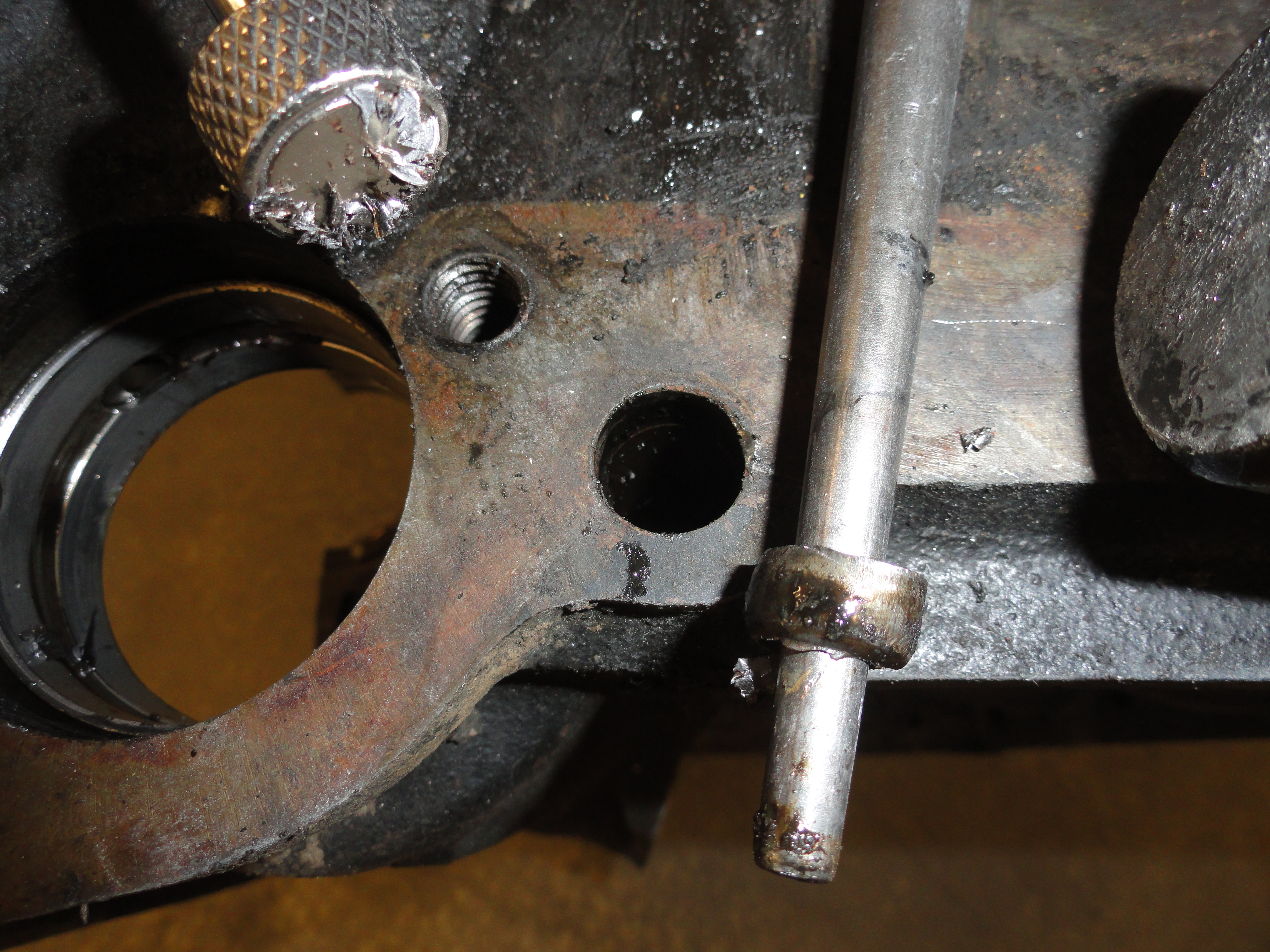
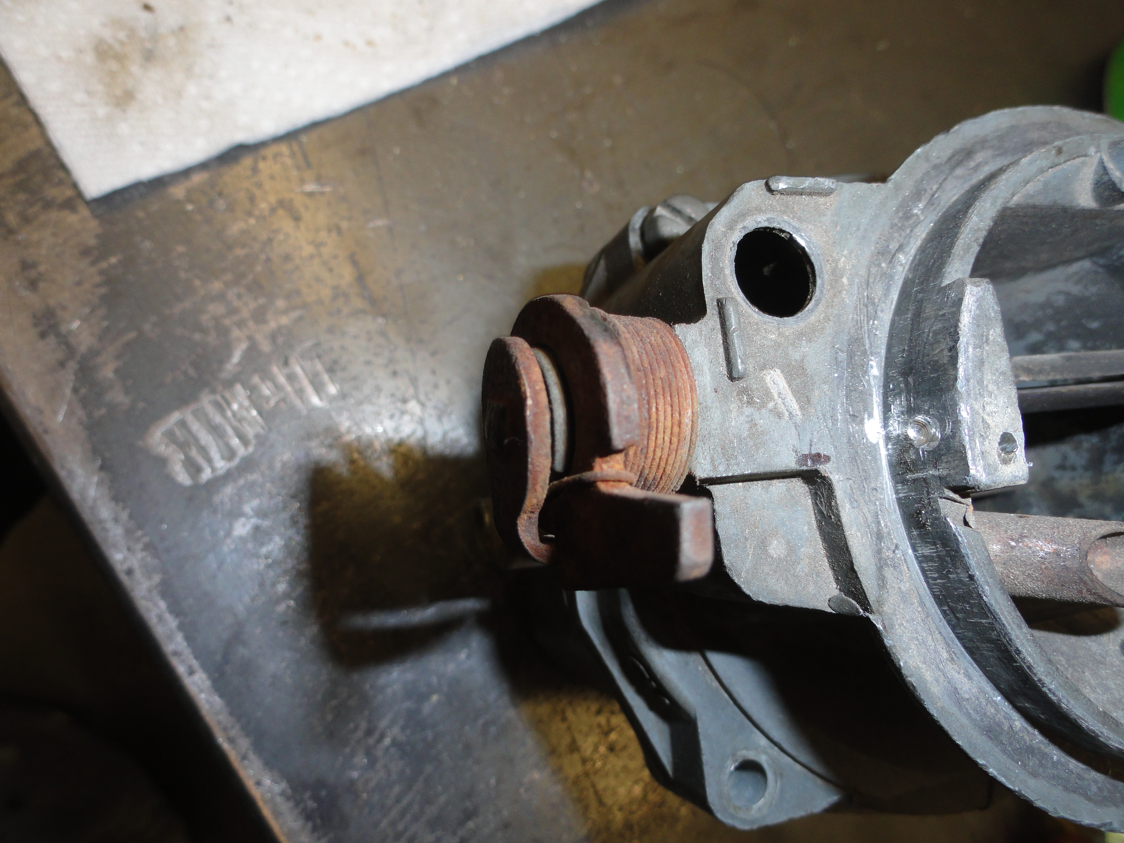
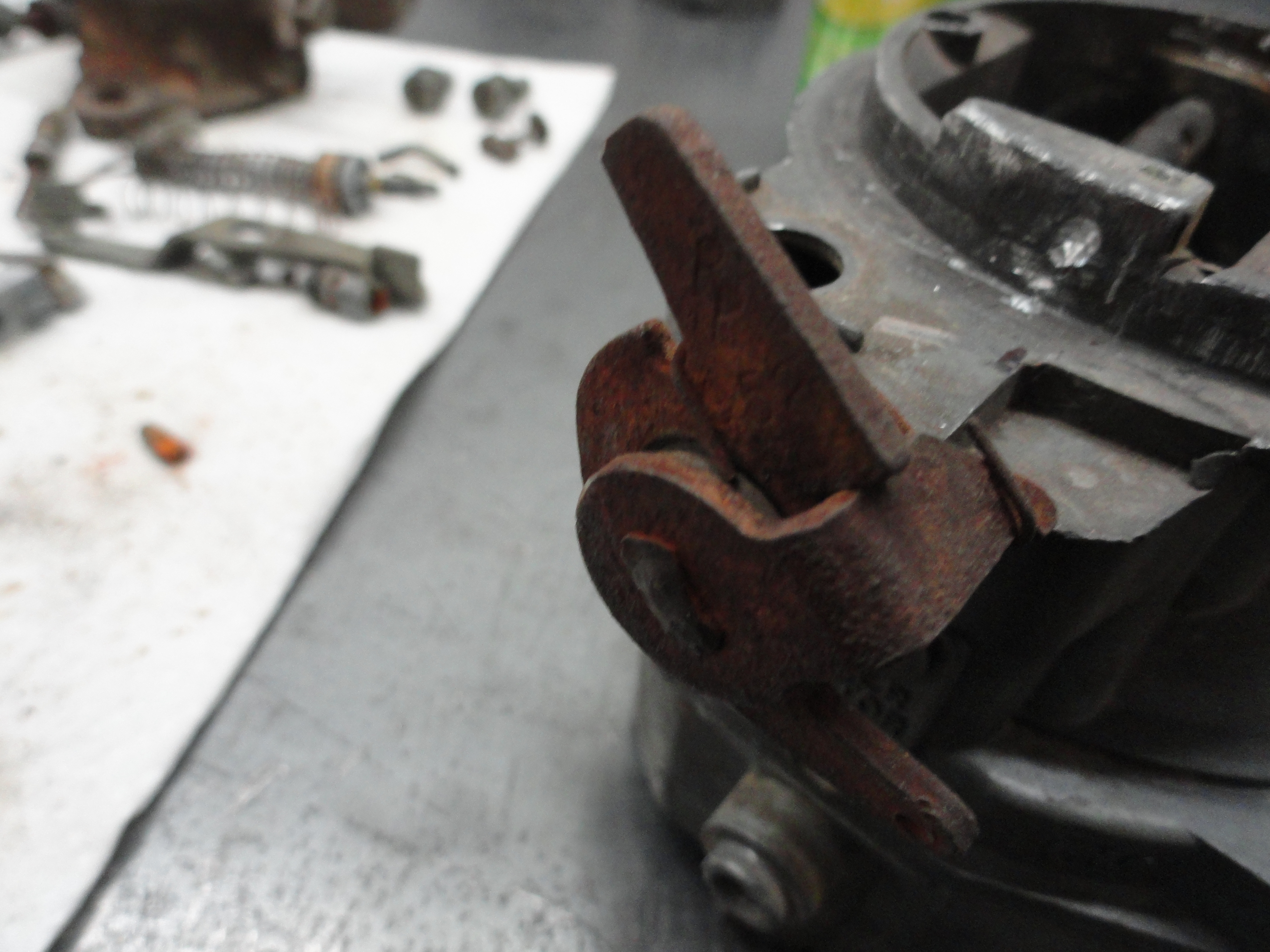
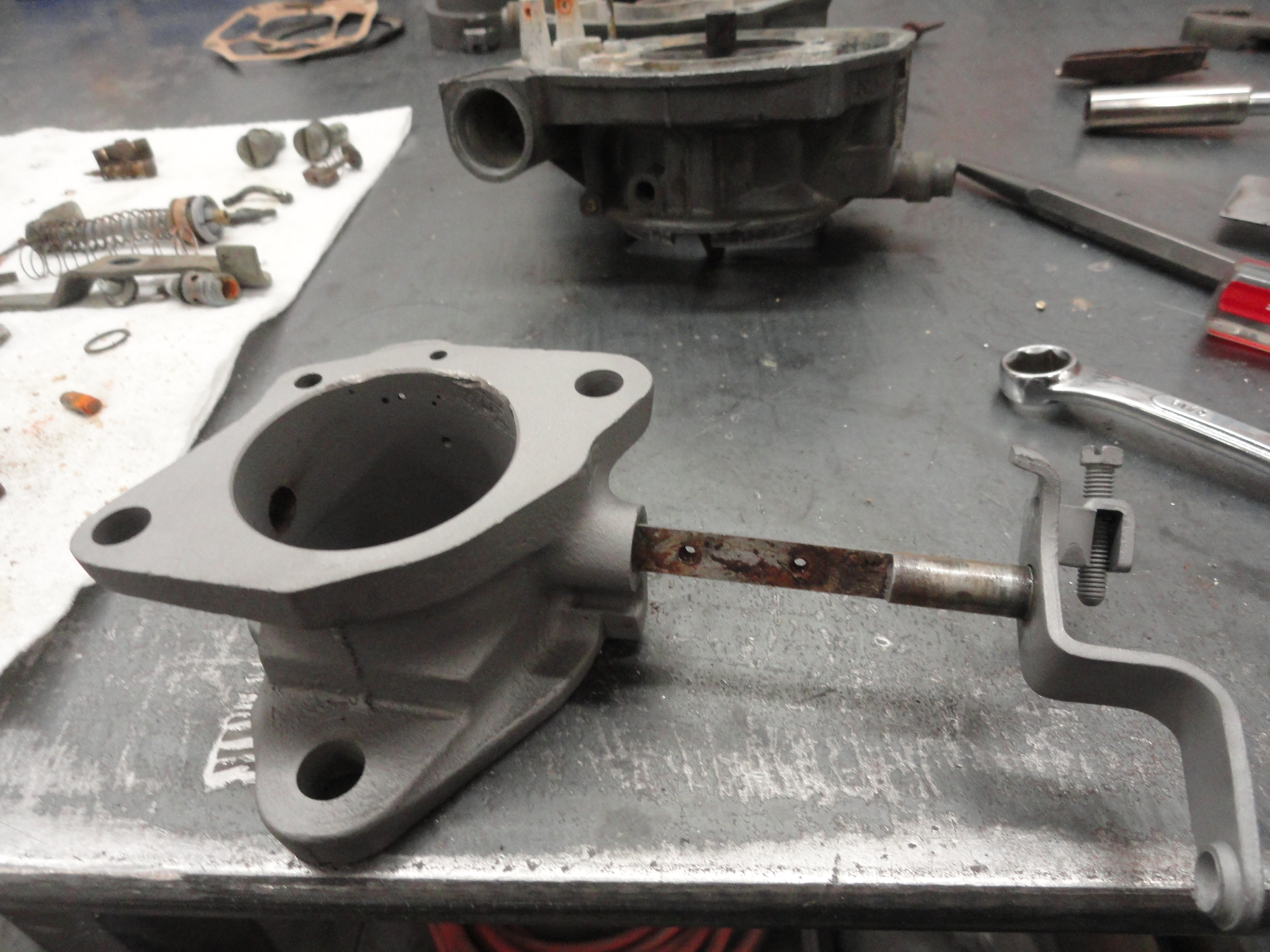
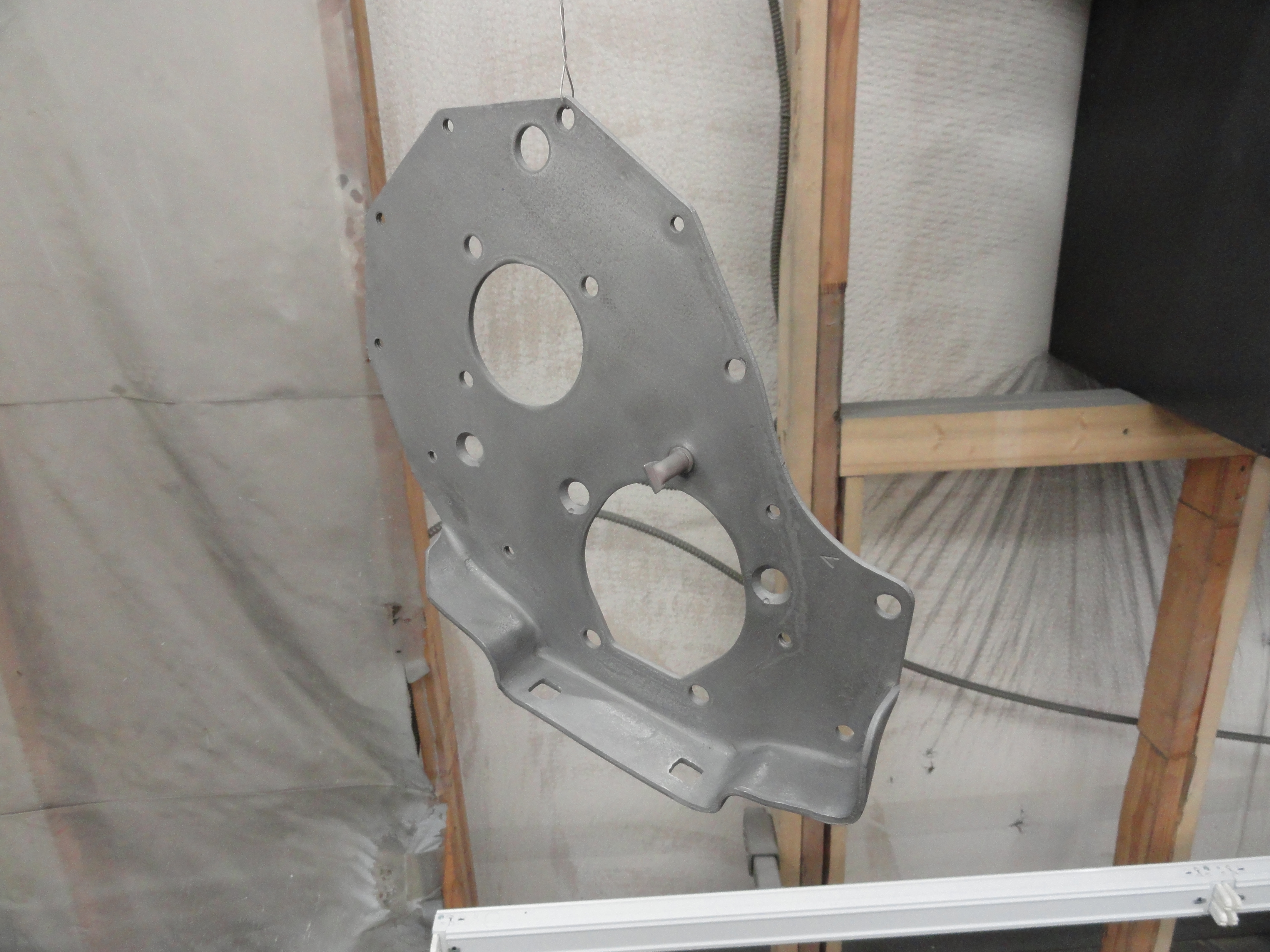
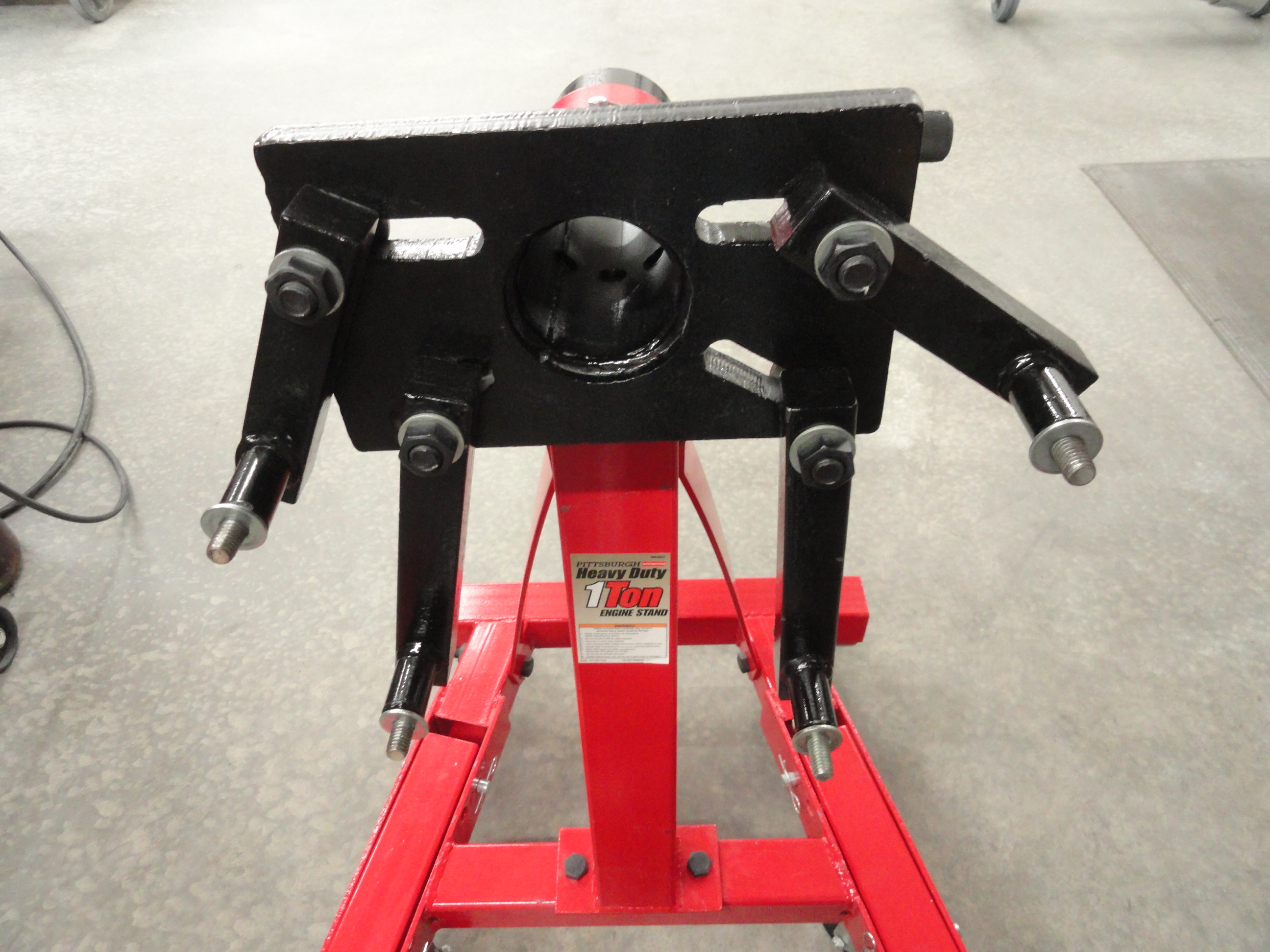
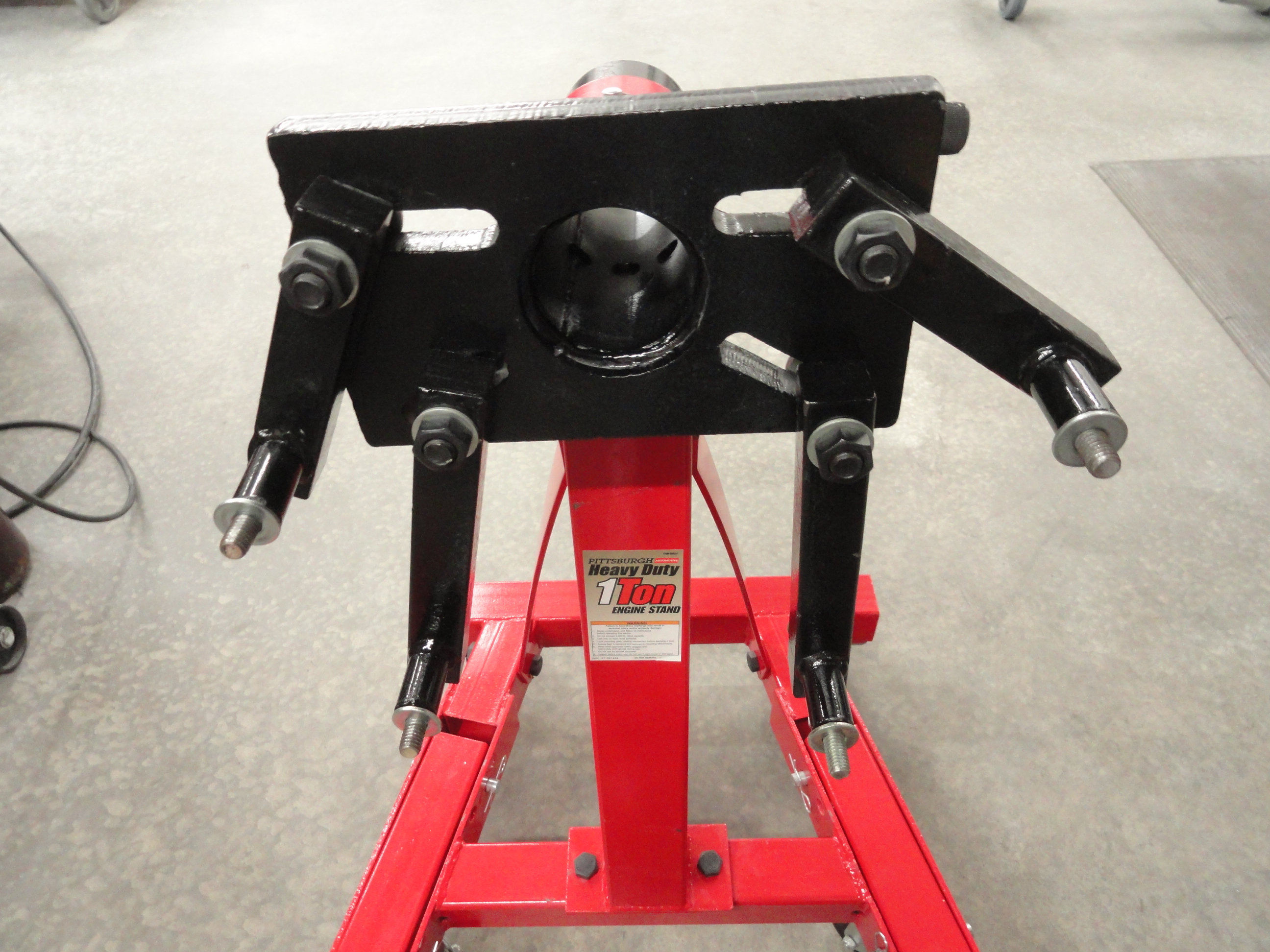
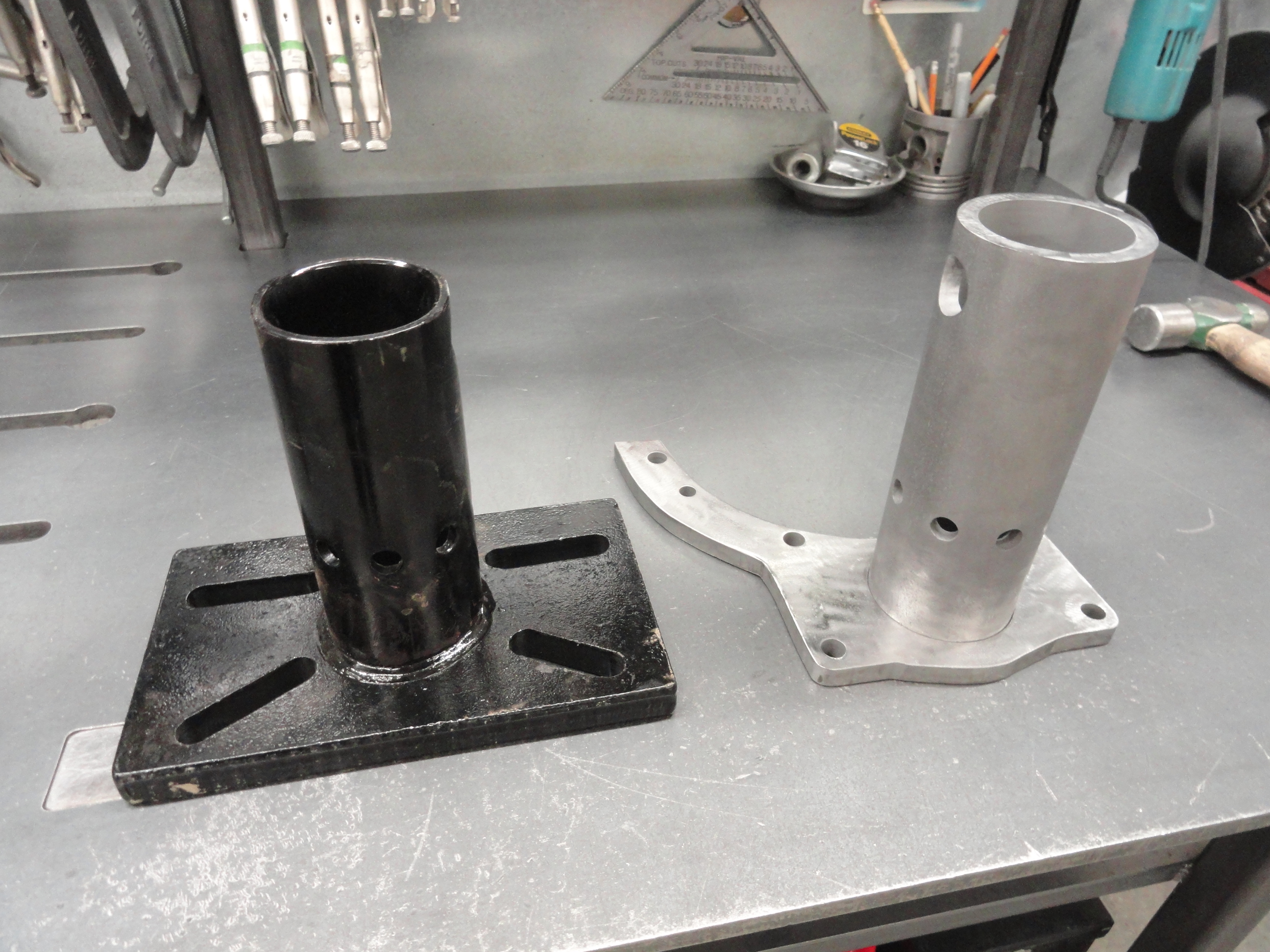
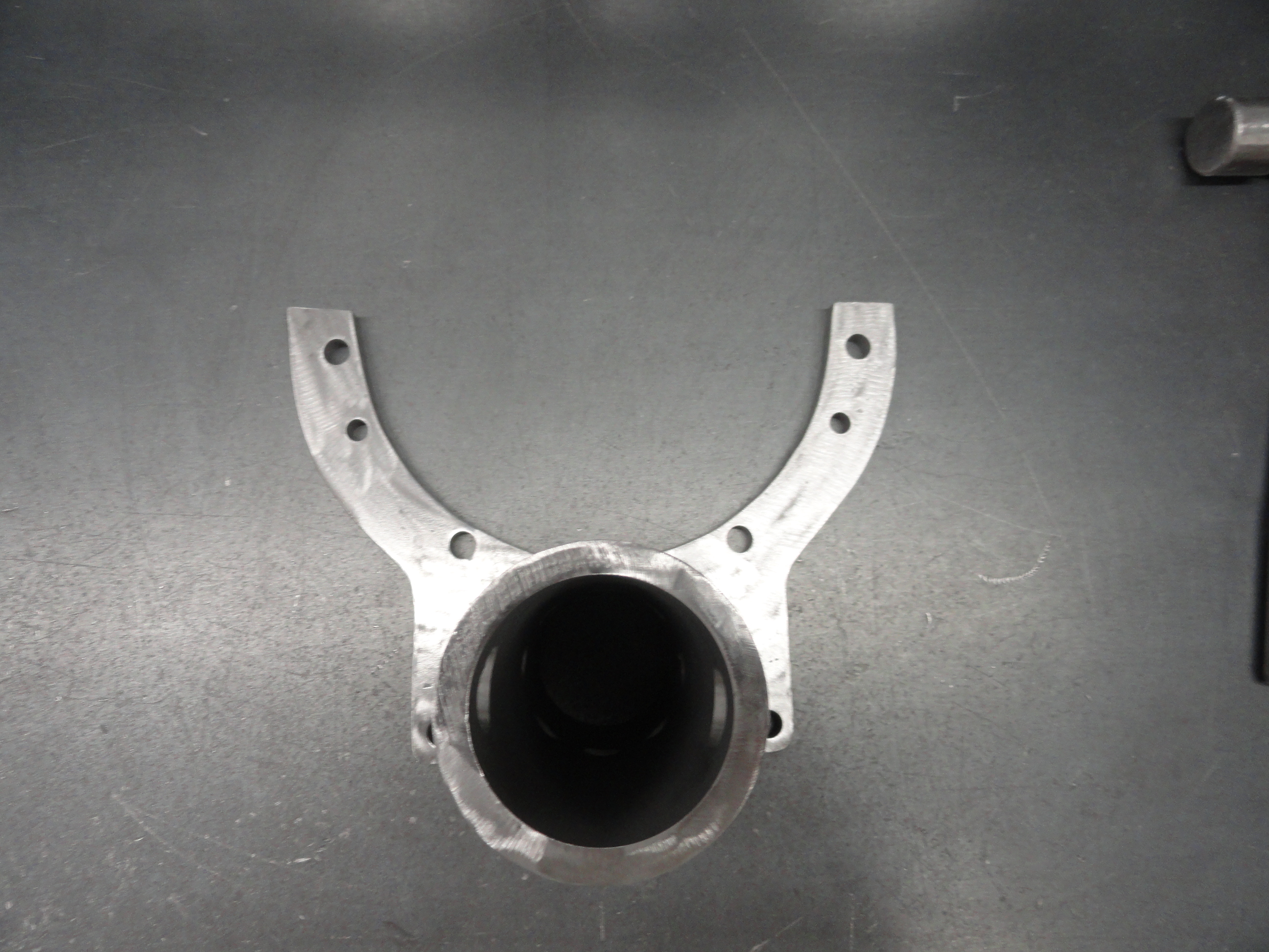
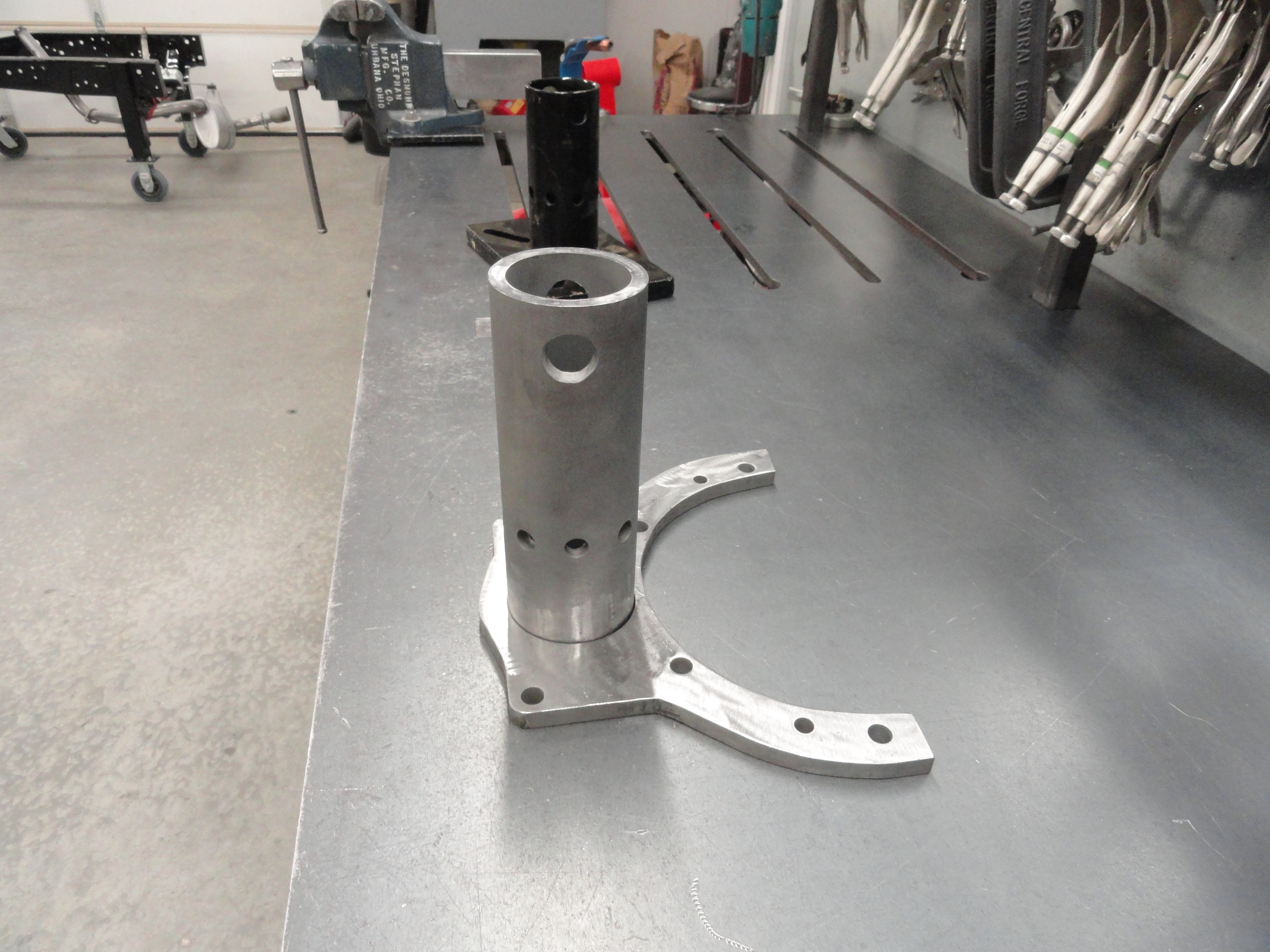
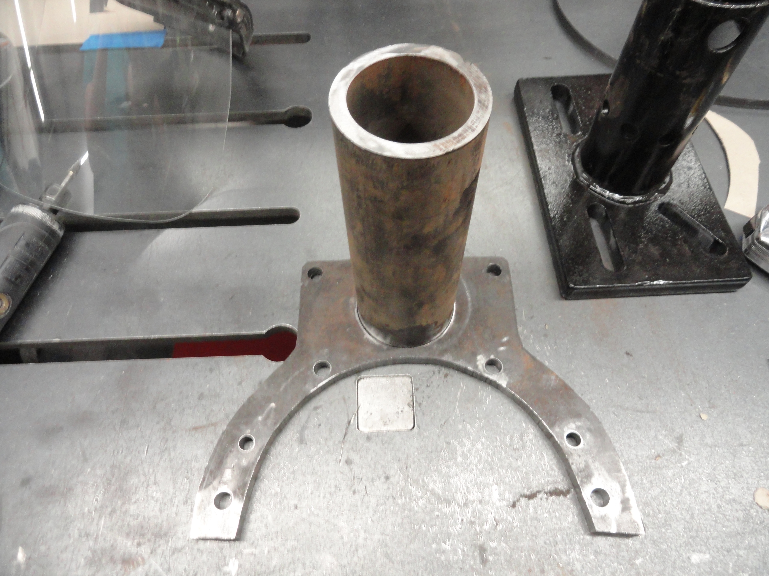
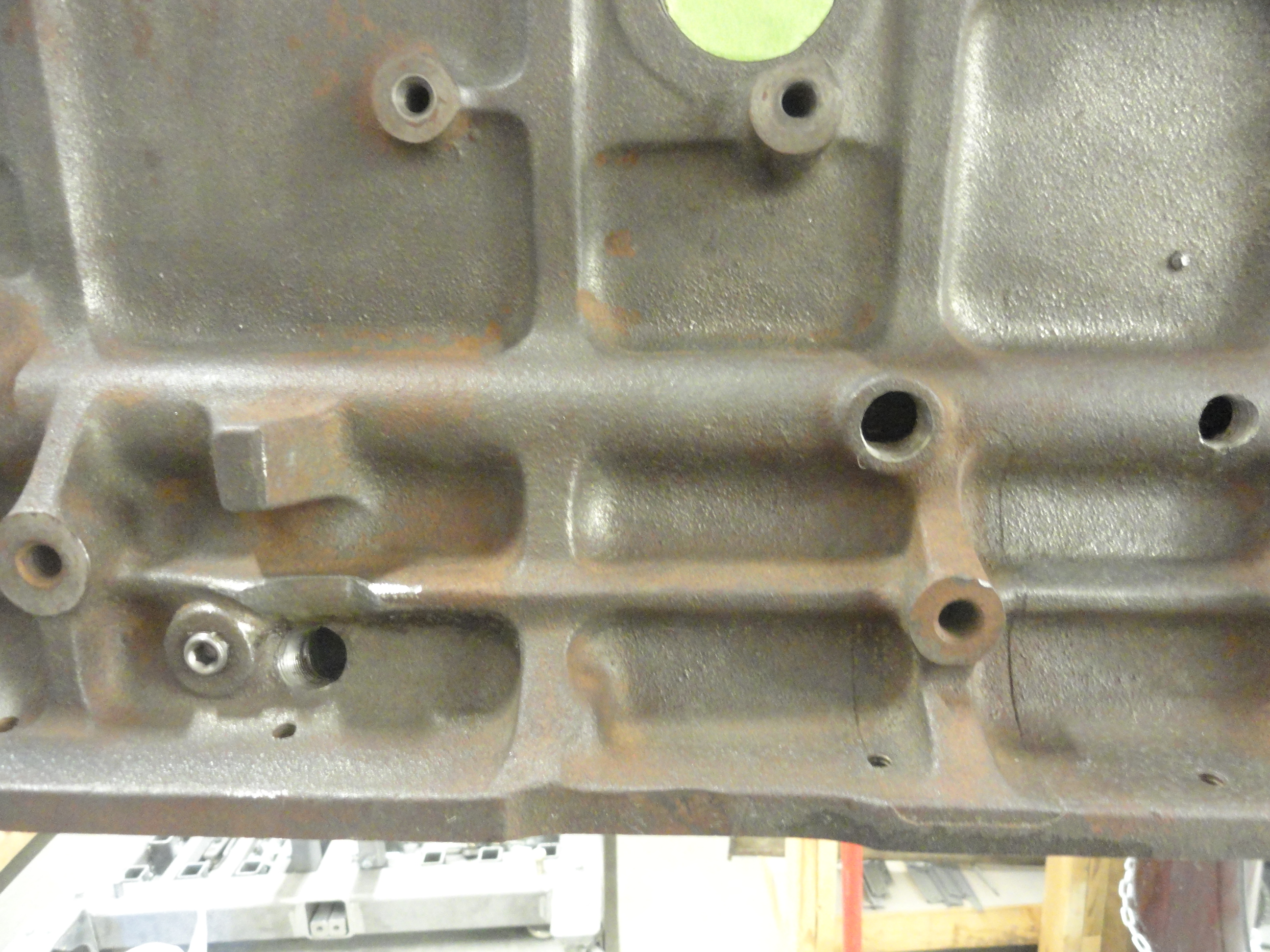
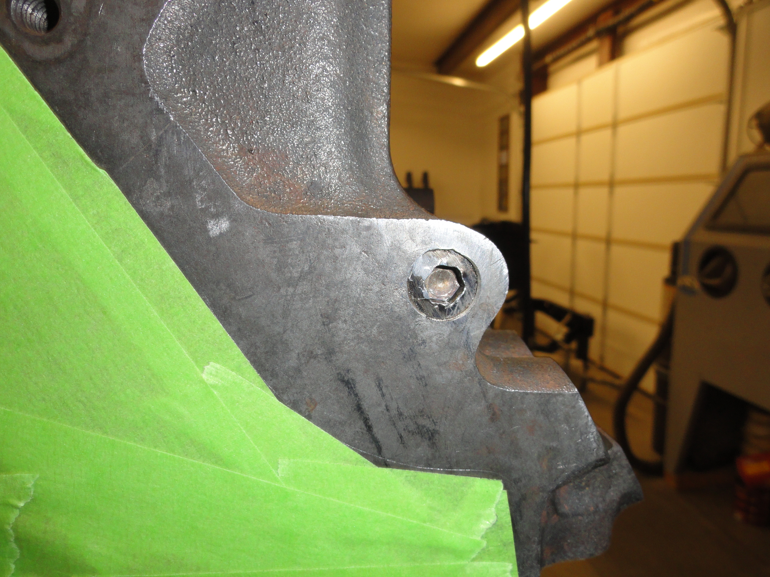
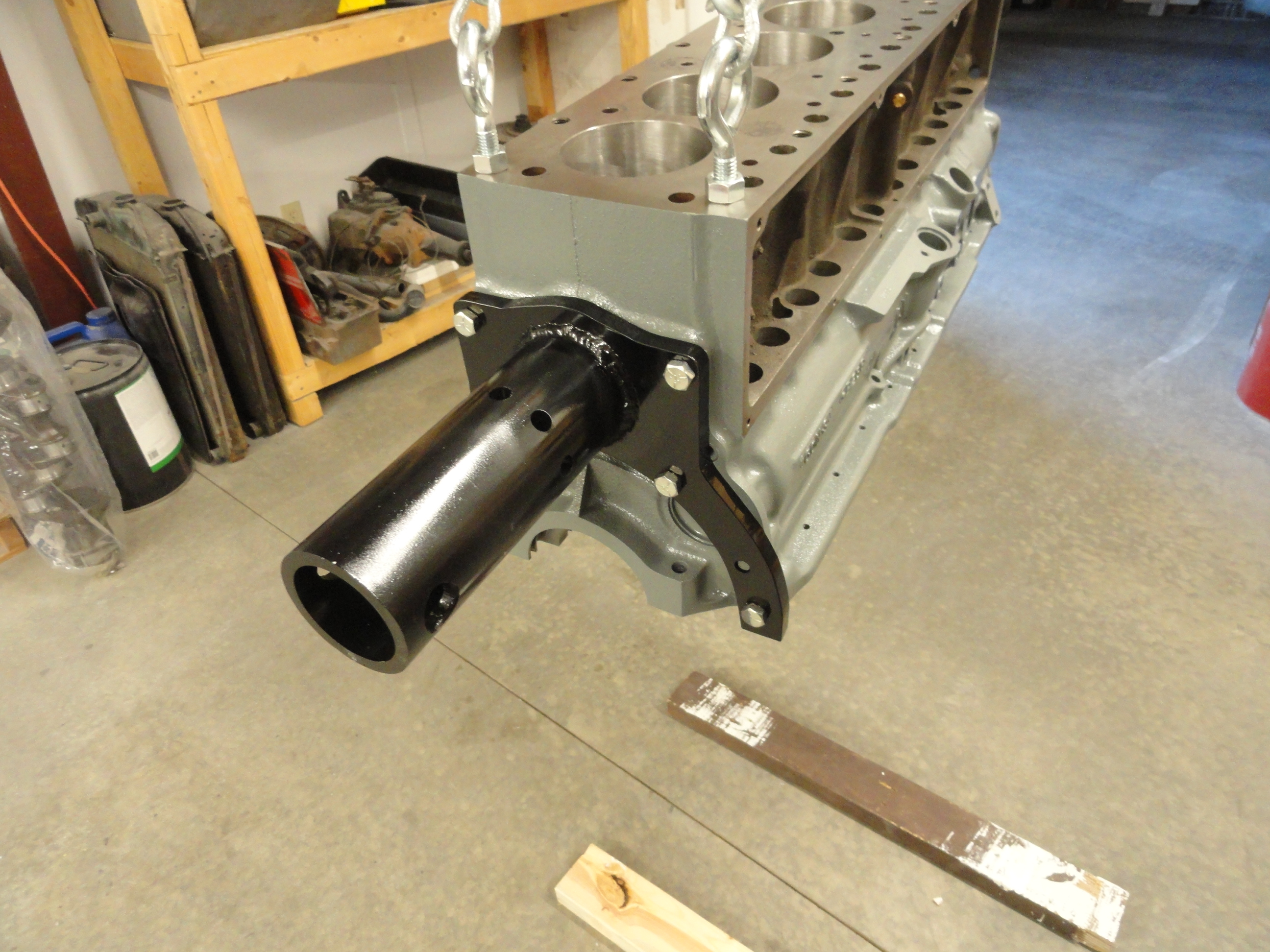
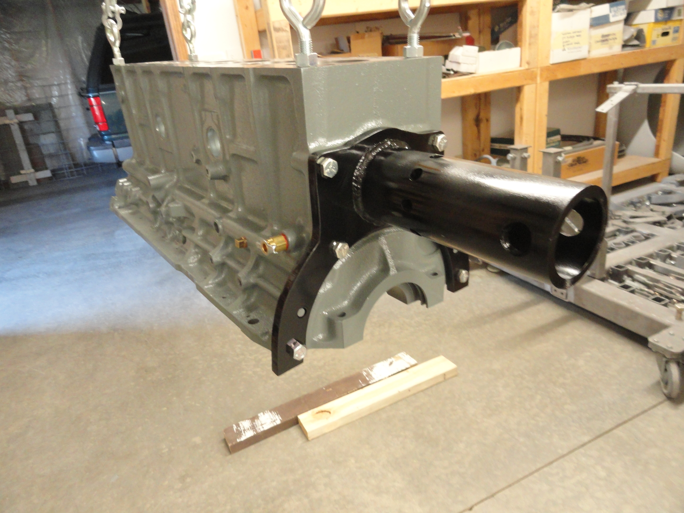
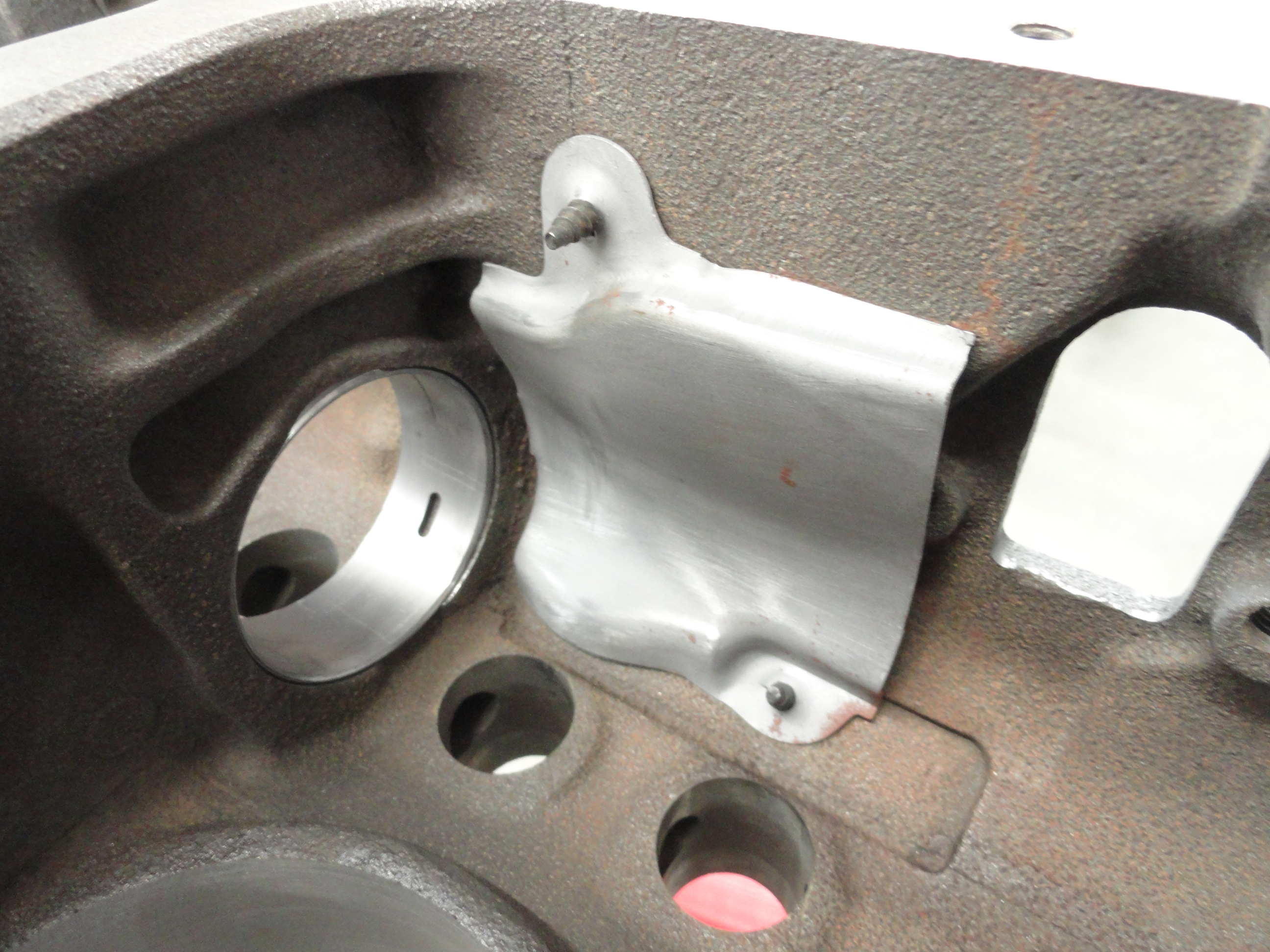
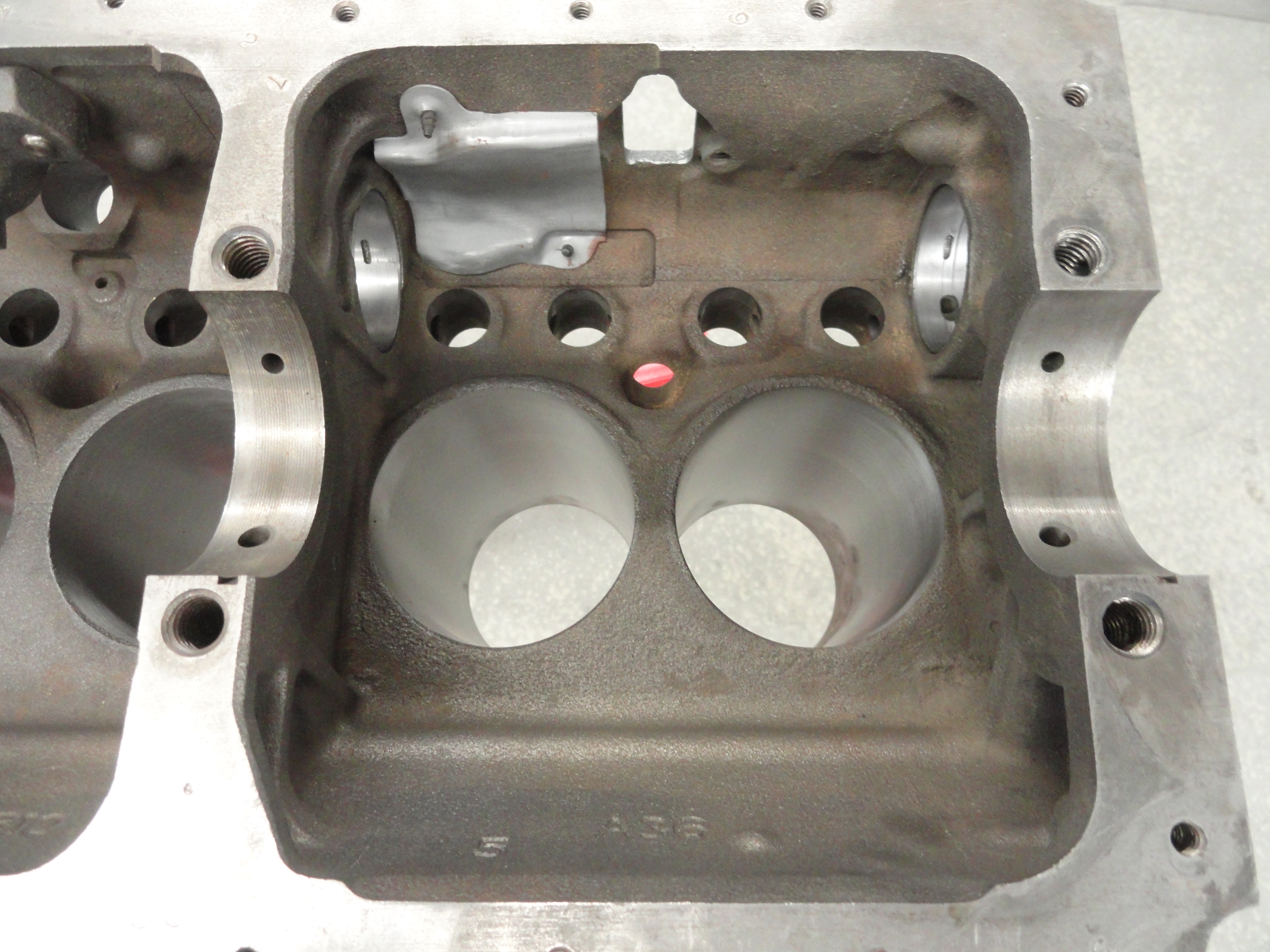
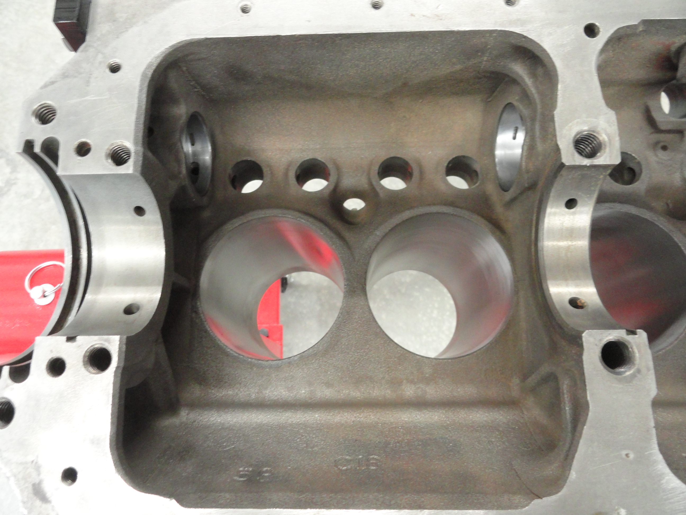
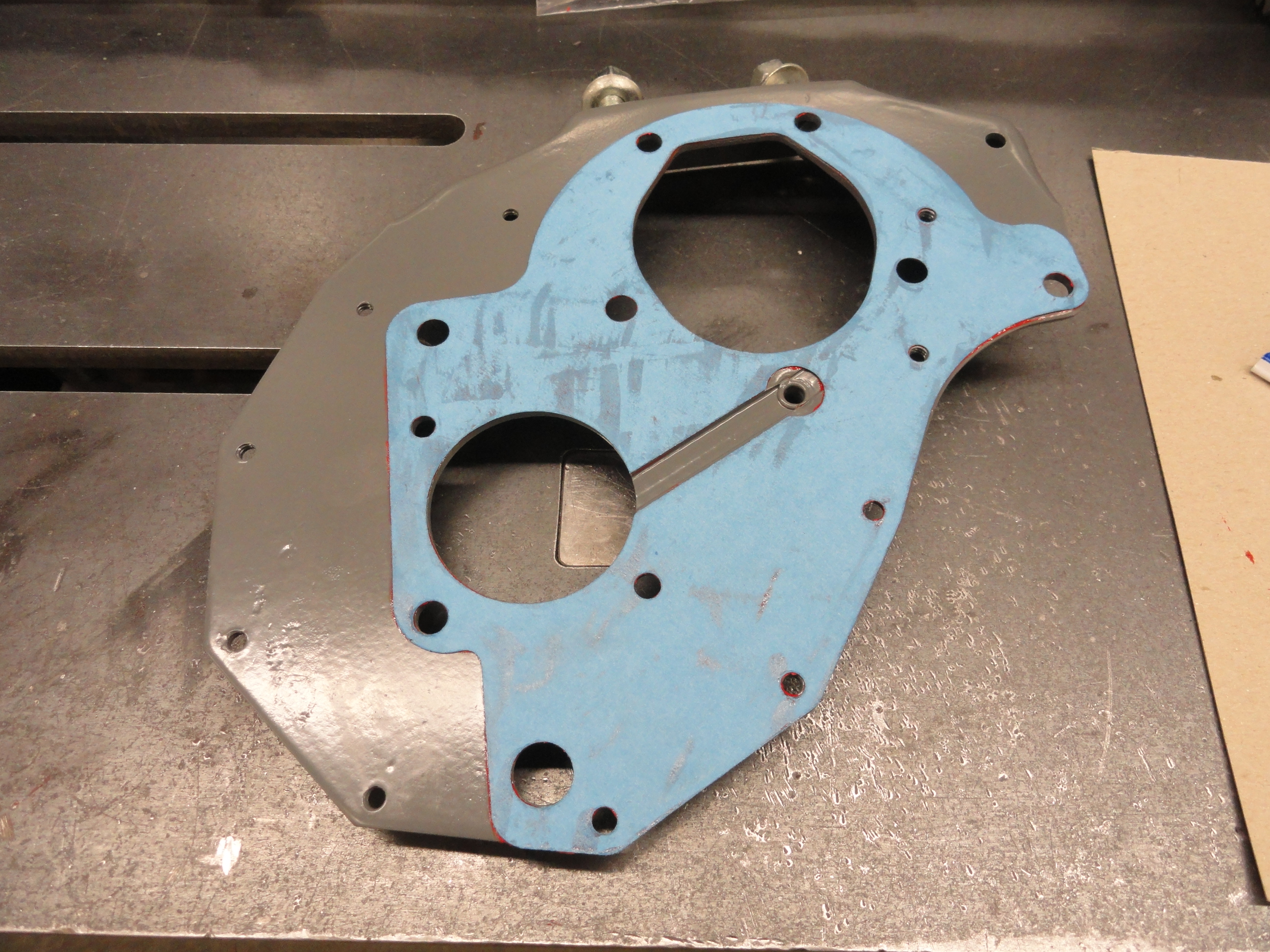
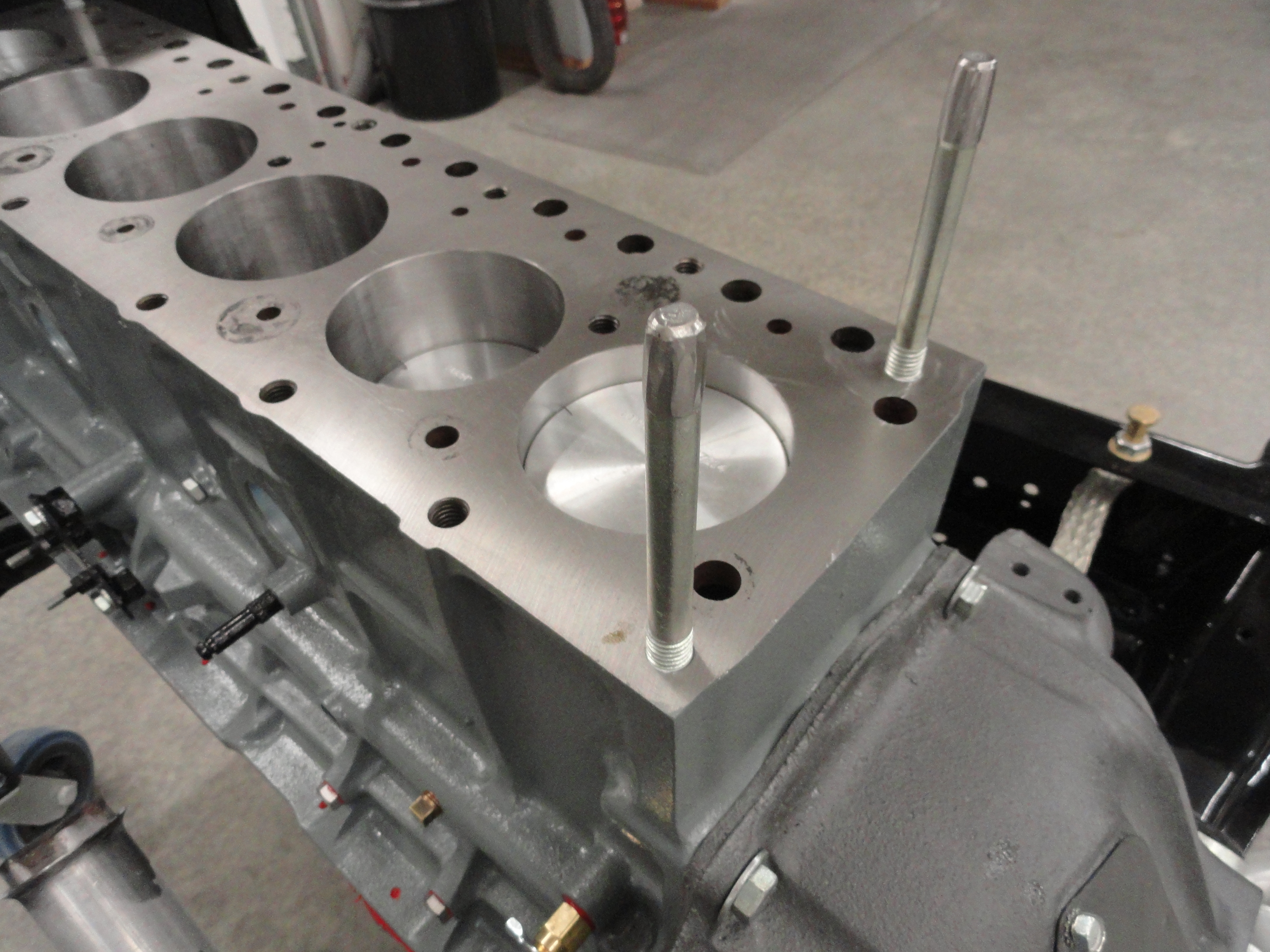
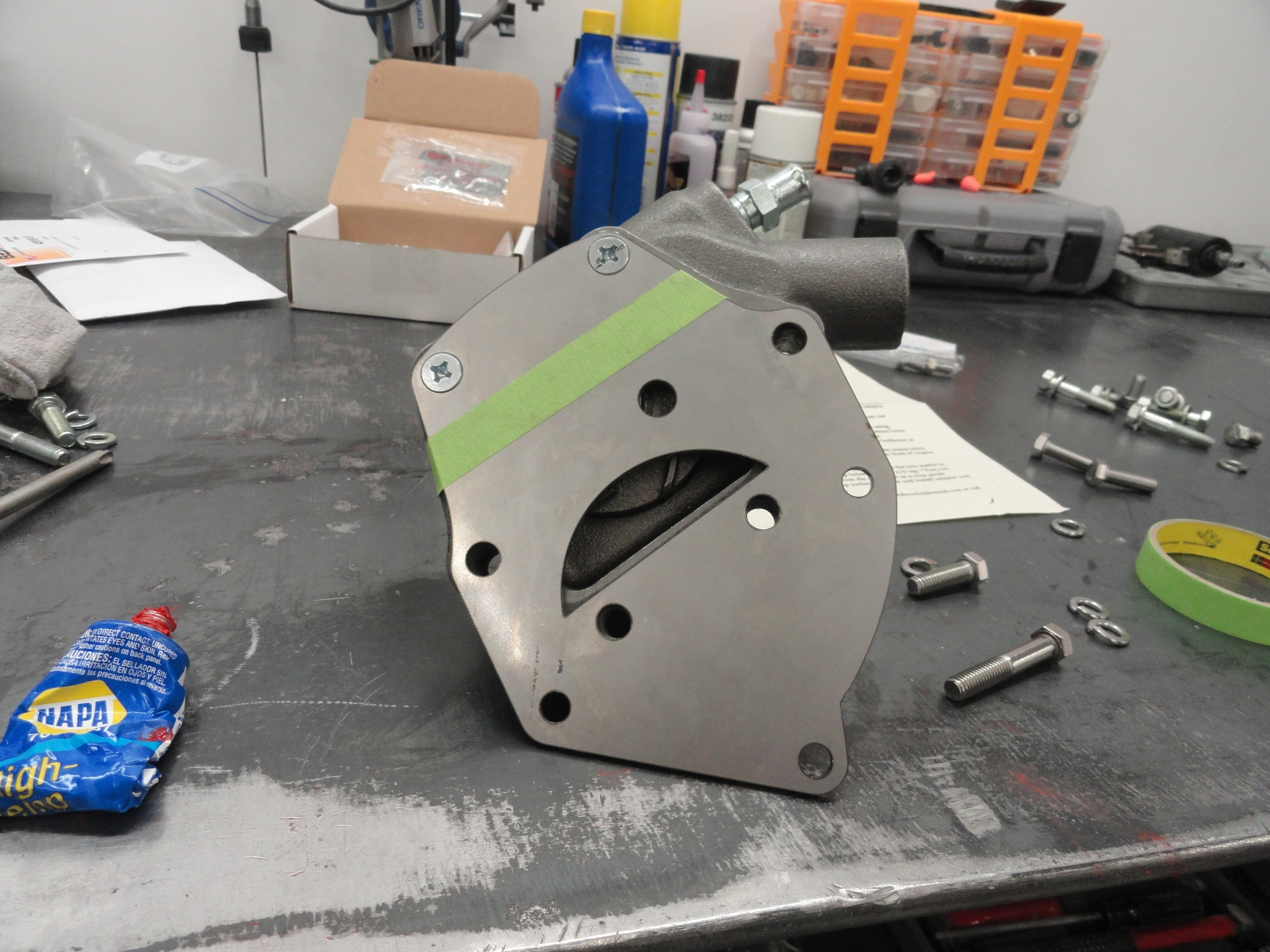
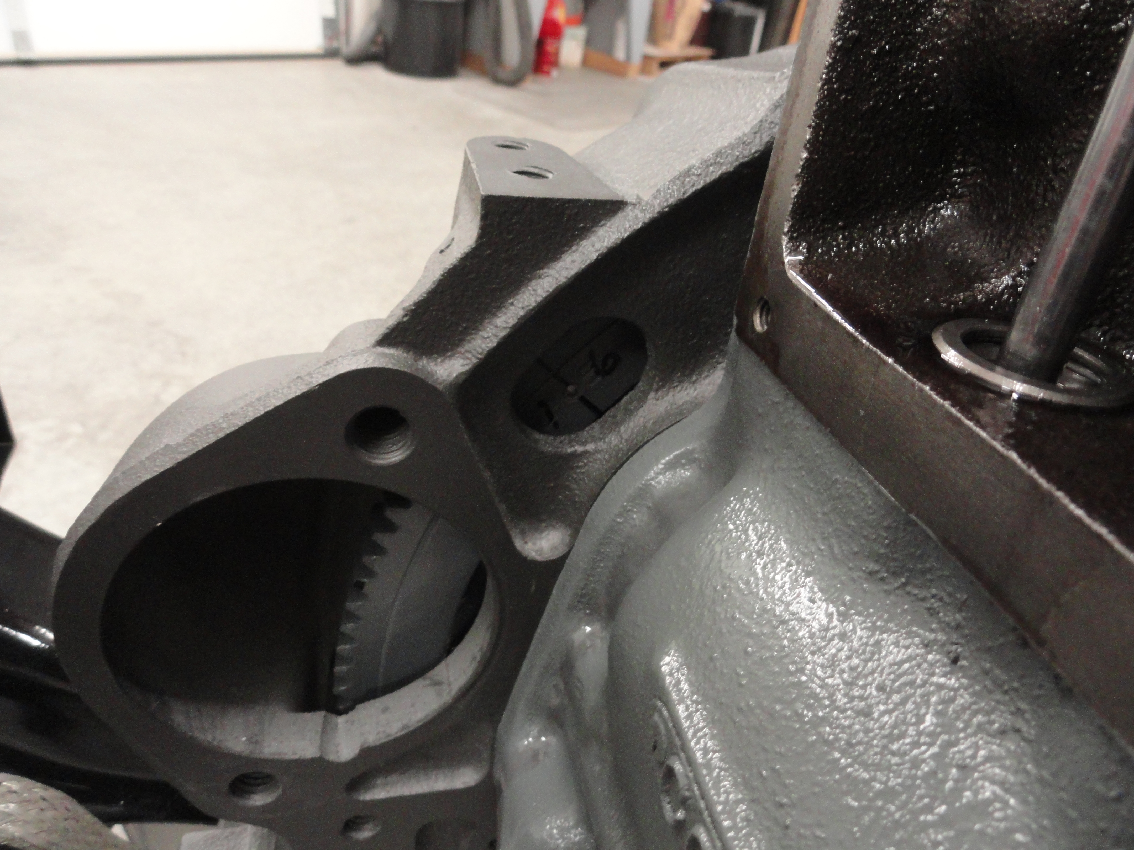
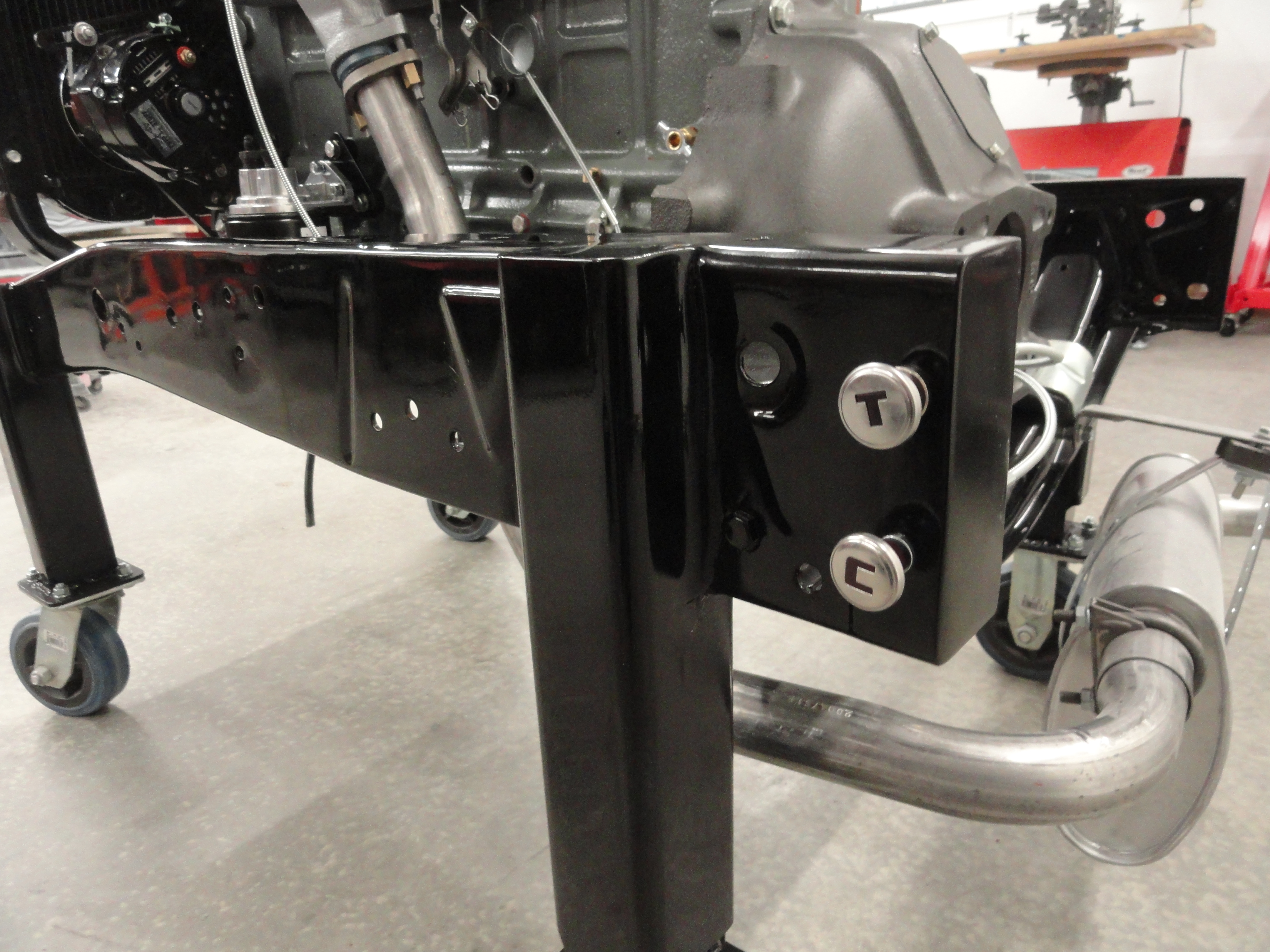
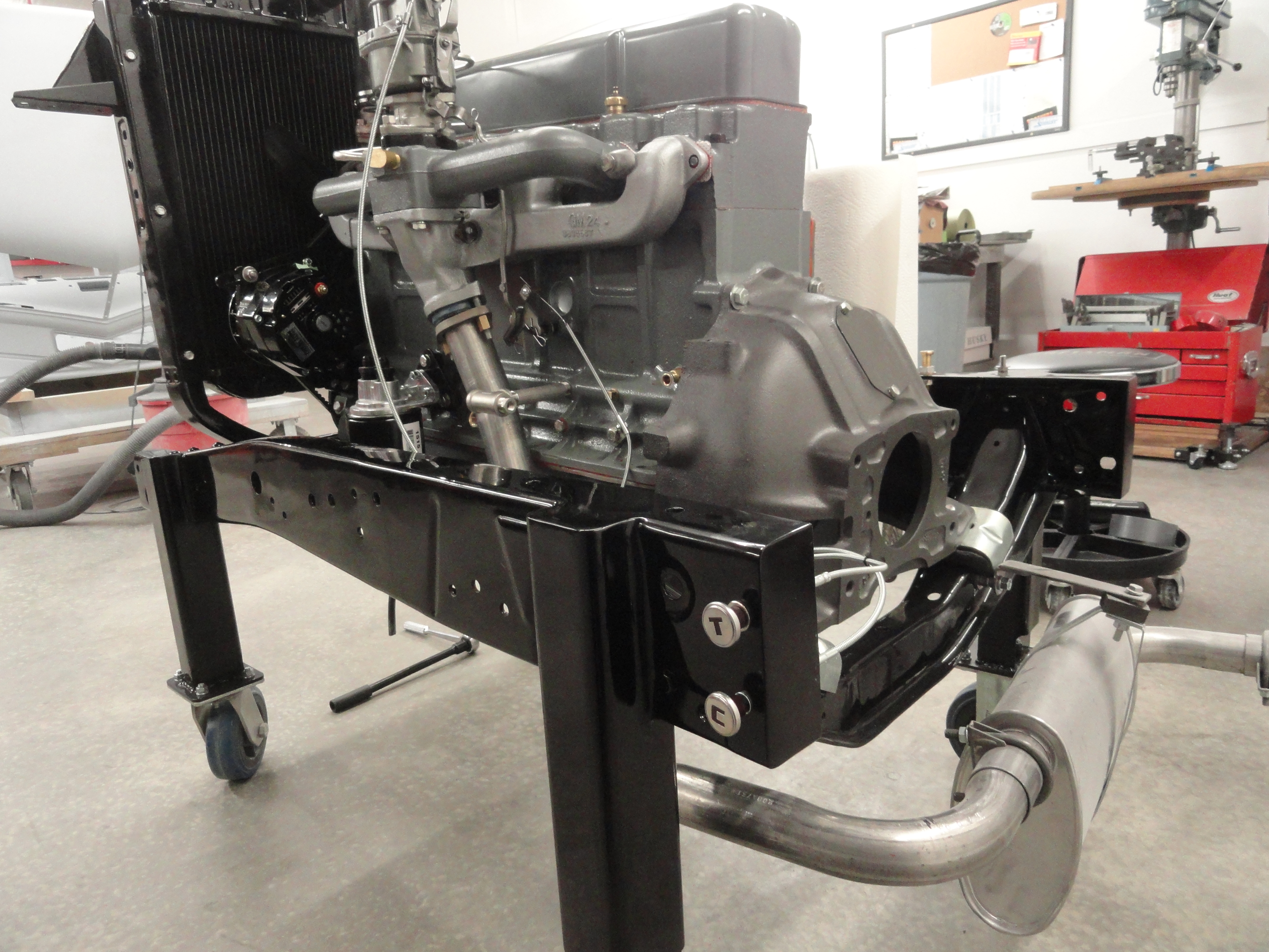
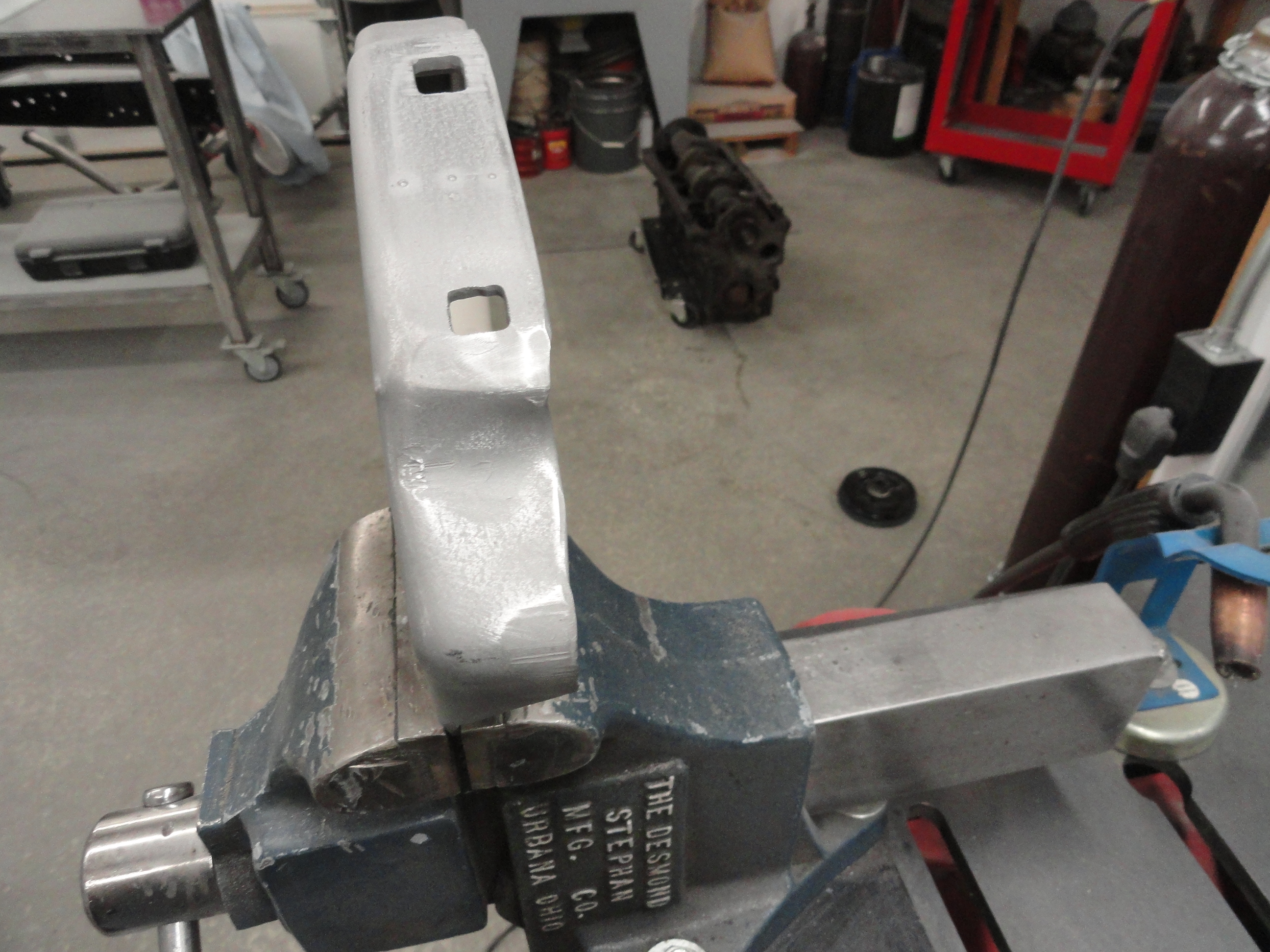
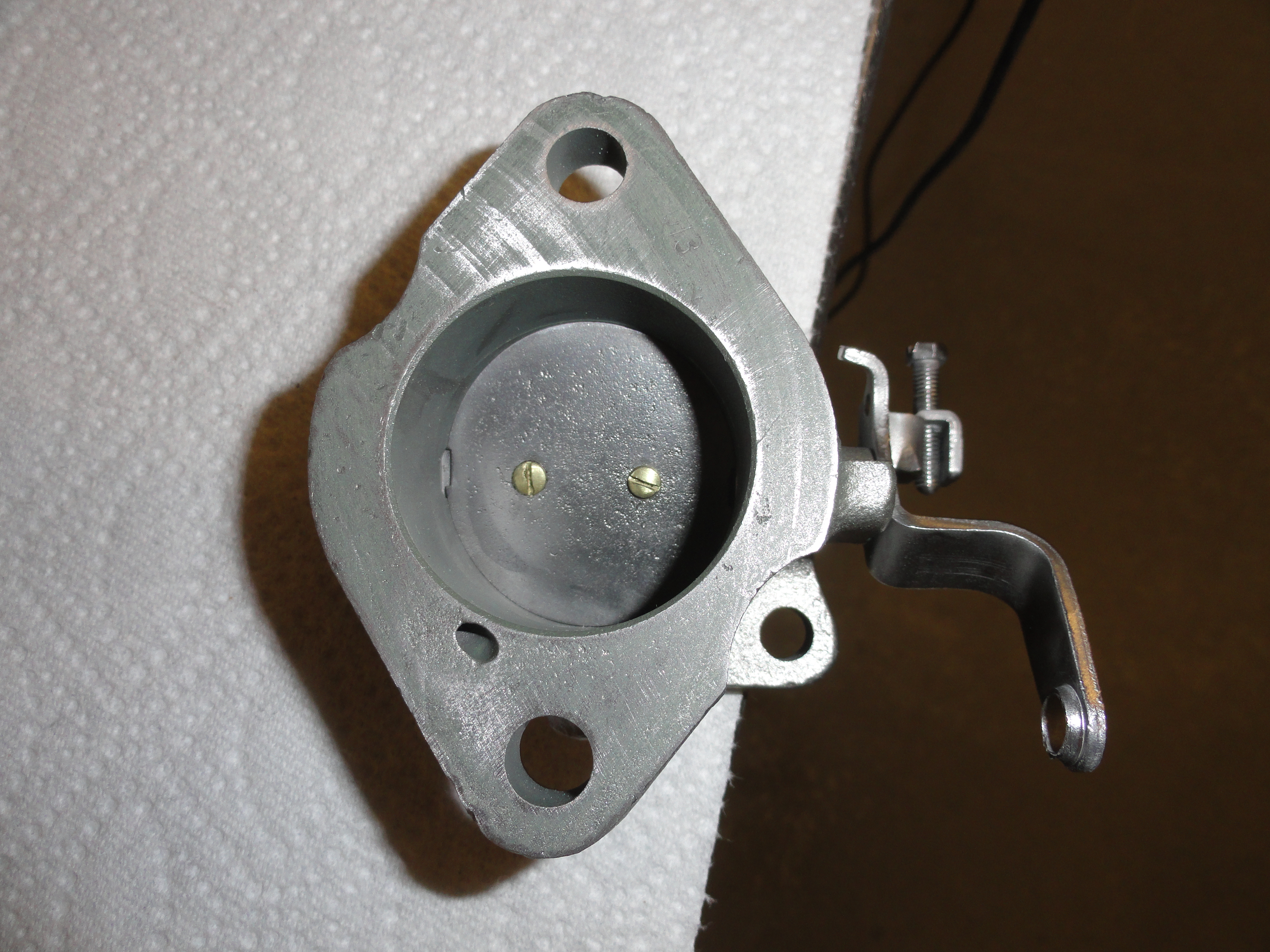
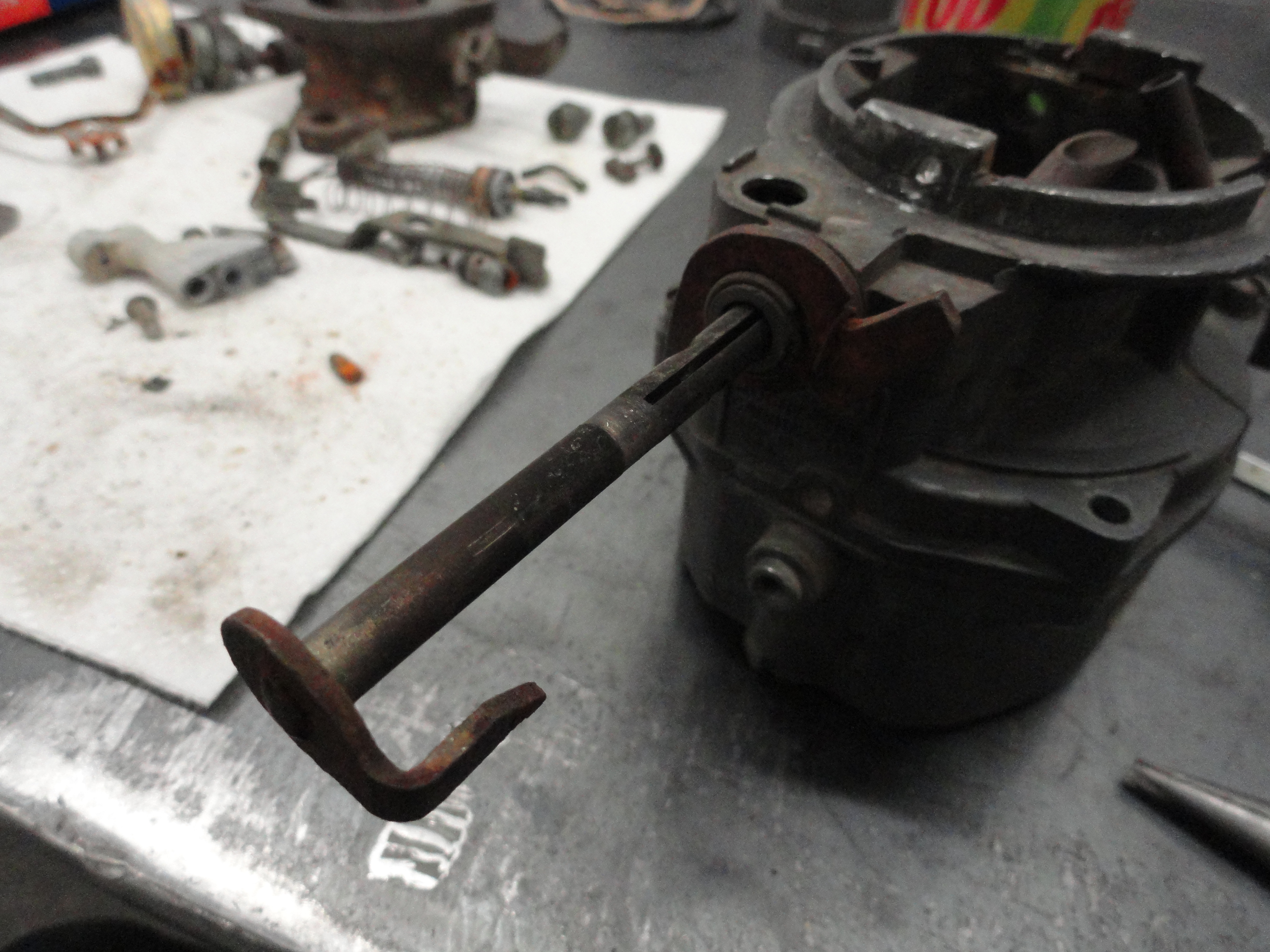
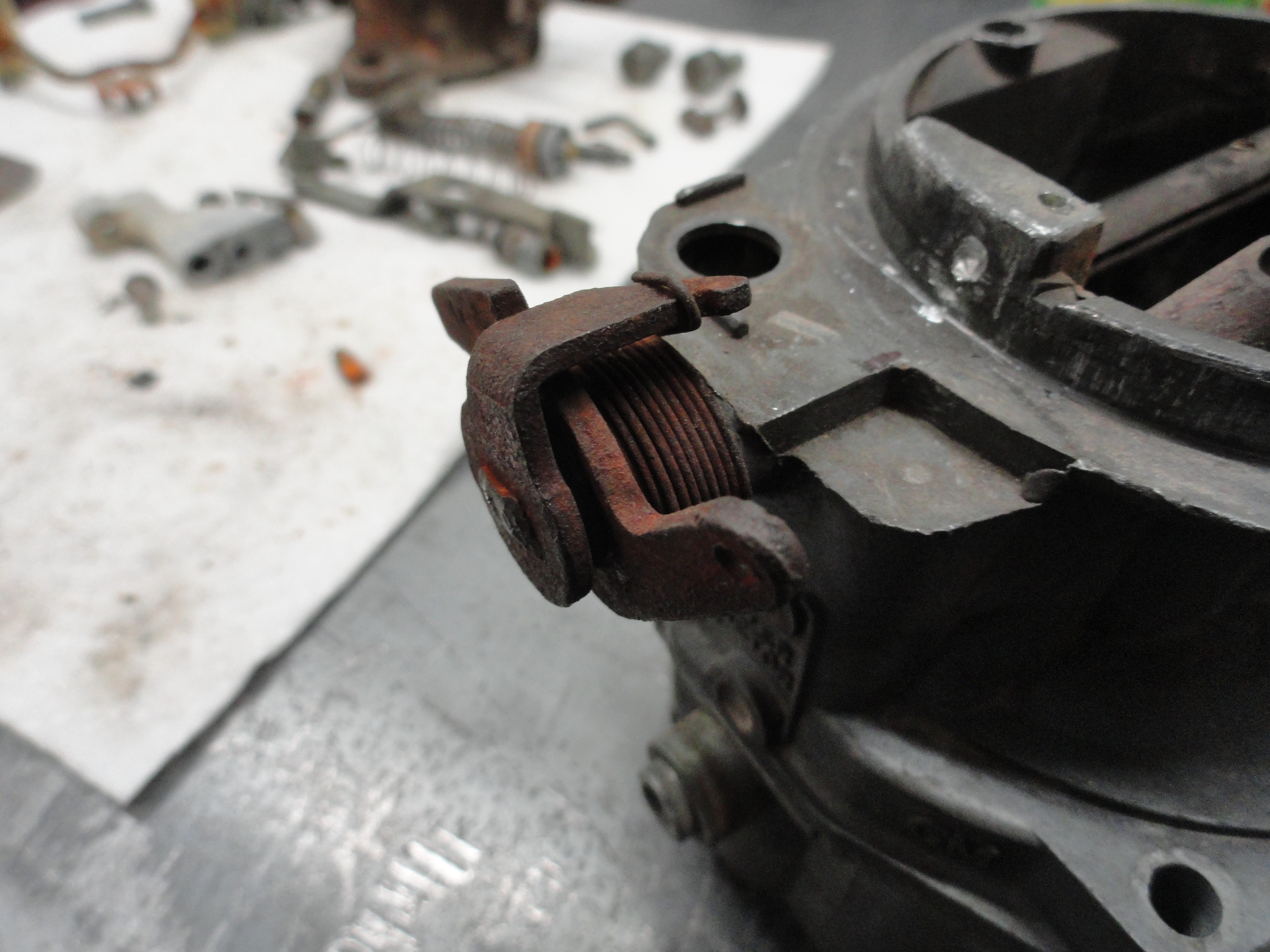
As you all know, devestechnet.com specializes in 47-55 Chevy Trucks, so we have a problem that we must address because of this engine being out of our specialty years. This problem exists in the later years of the series, 1958-1962. It has to do with the Motor Mounts and the fact that the newer engine was mounted differently. The good news is, Chevy kept the design of the engine the same as earlier years, so we can still use it with a minor modification. We need to address this while the engine is apart. You 'could' do it when assembled, but happens that we don't have to! Looking at these pictures, you can see what we have to do. This is where the front motor mounts go in 47-55. The bolts are 7/16" fine thread Carriage bolts.
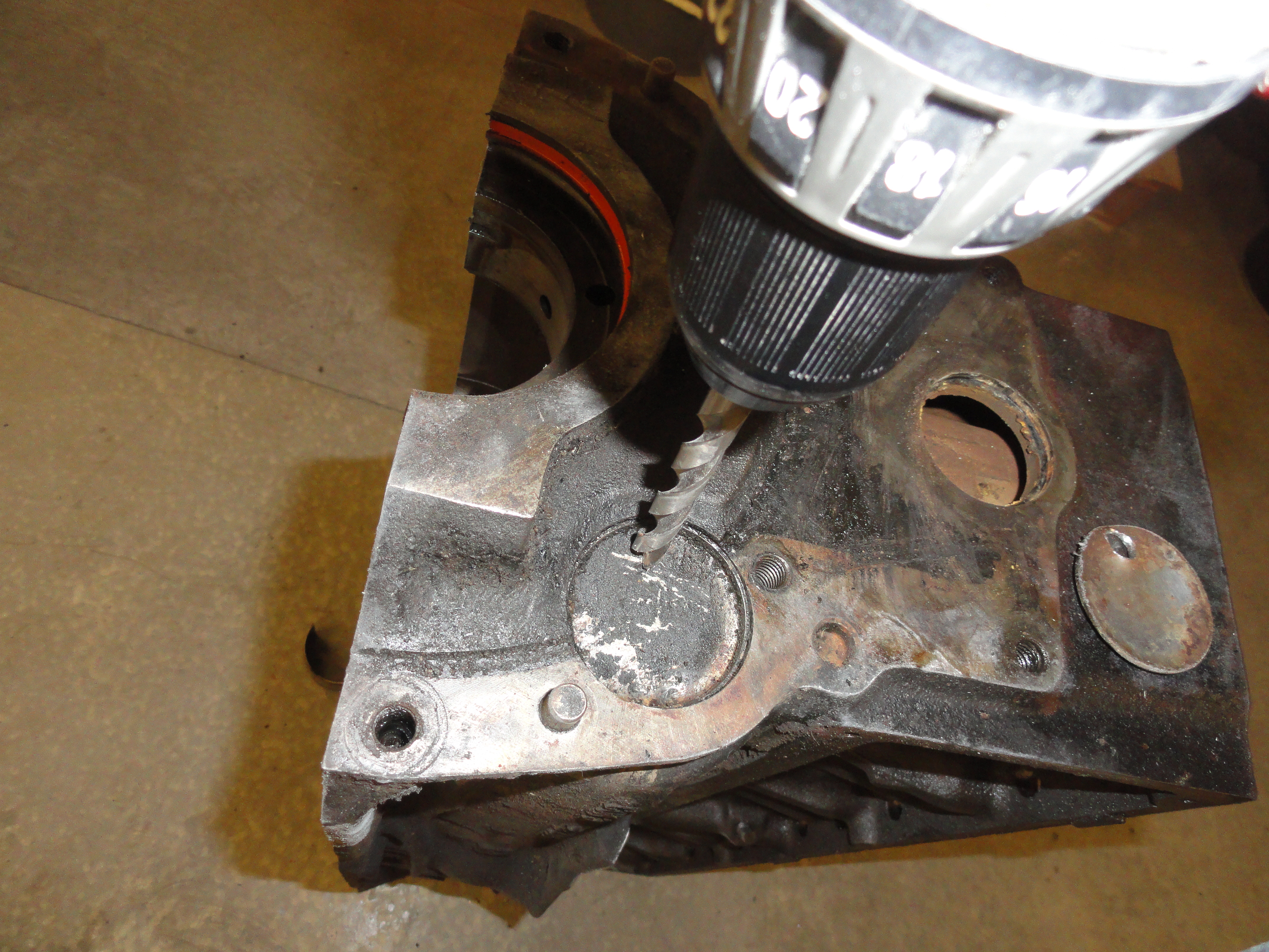
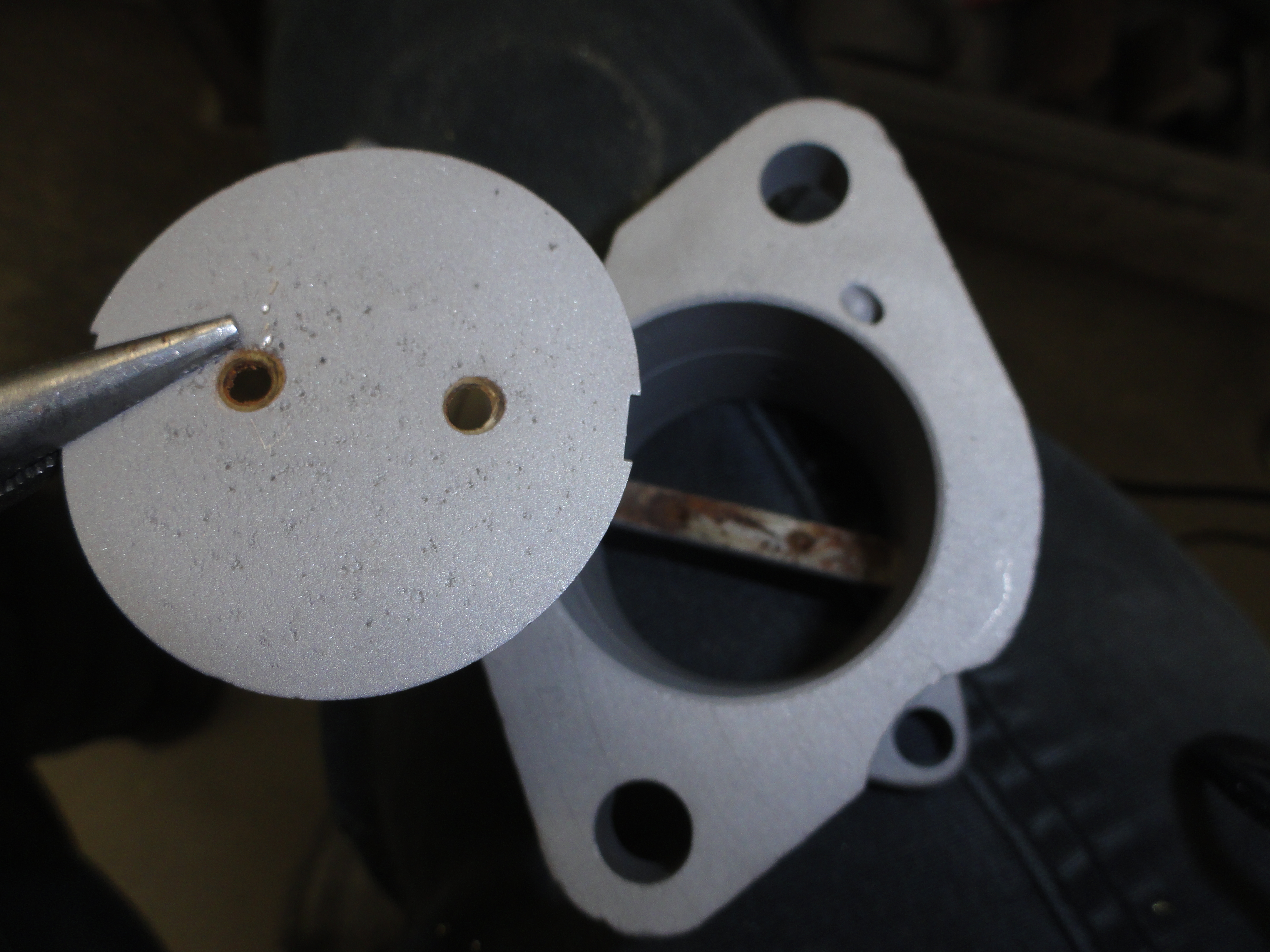
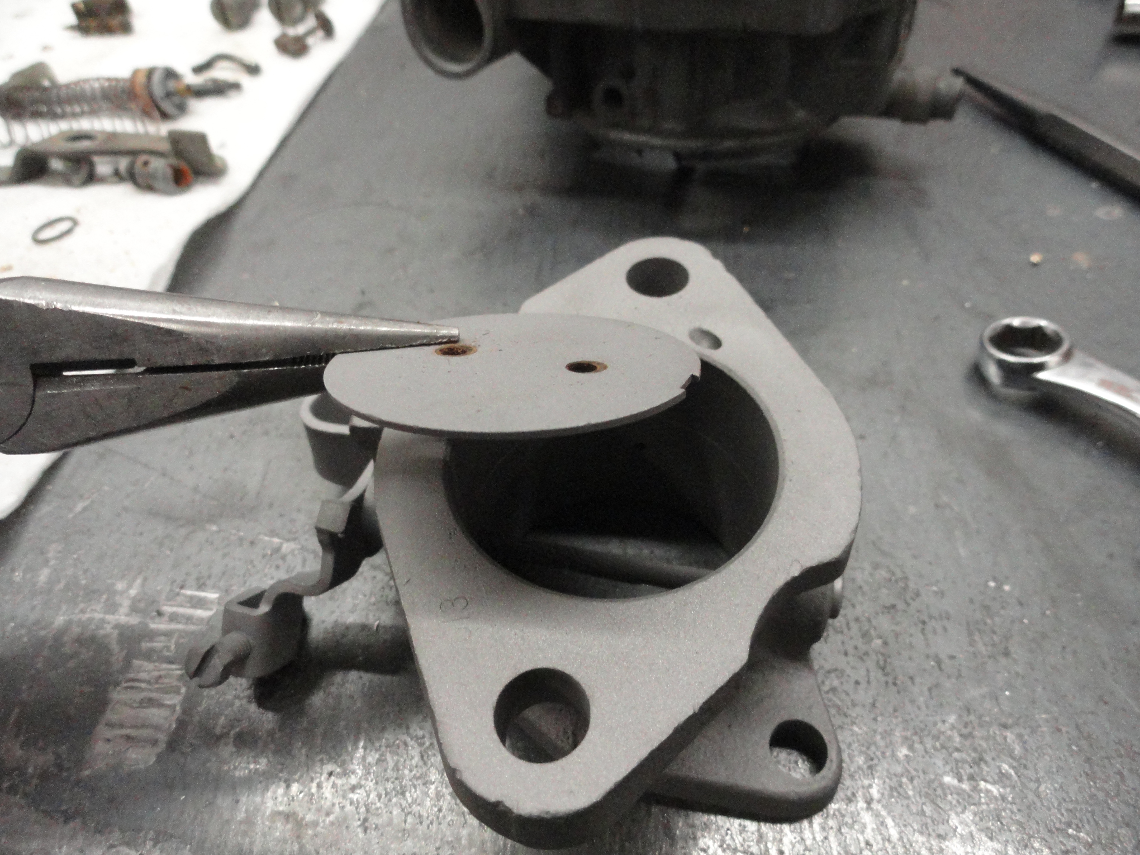
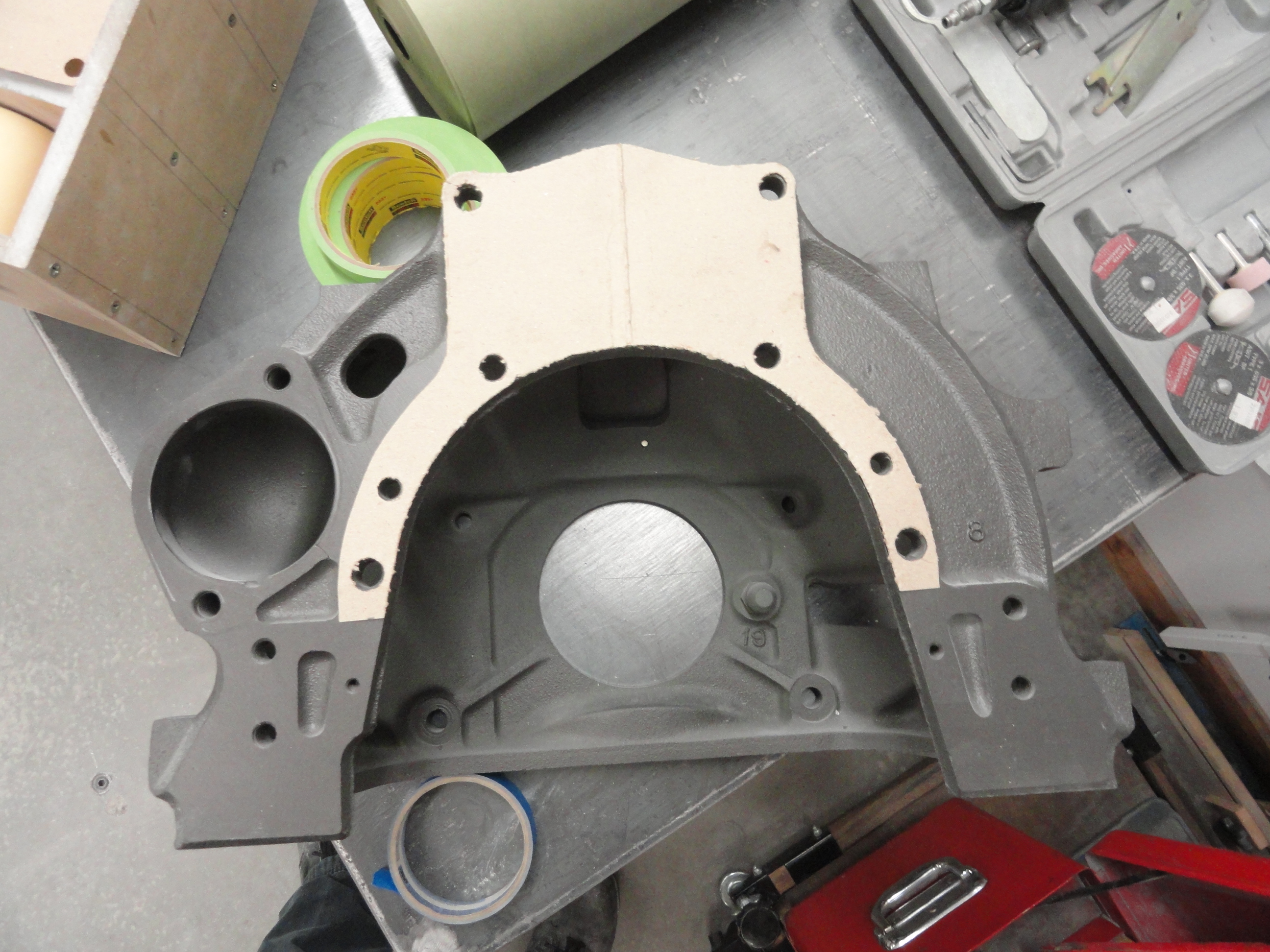
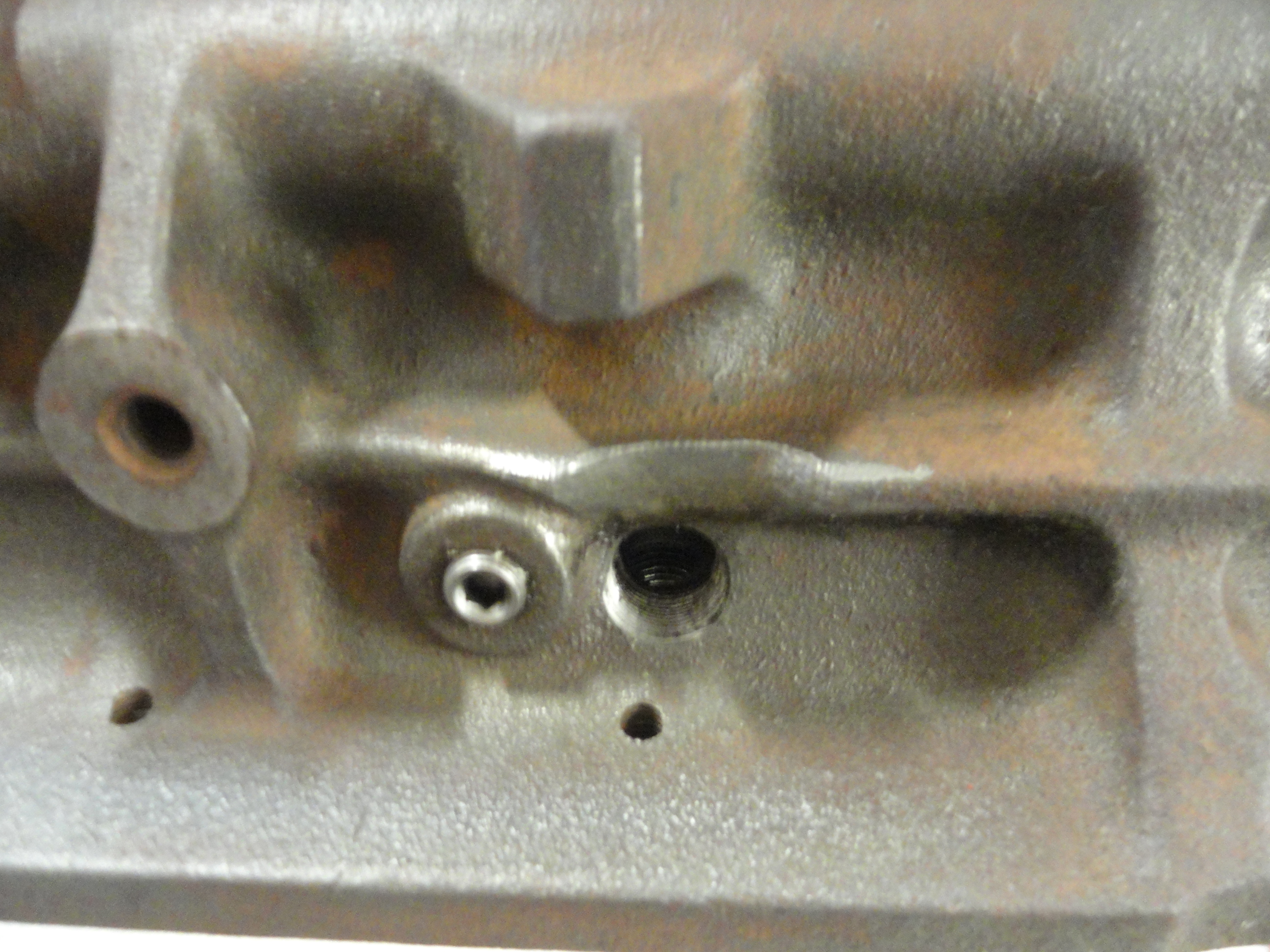
The plan is to drill the 29/64" holes using a standard drill bit, then with it marked carefully, use a Dremel tool and a carbide rasp to finish the holes to accommodate the square part of the carriage bolt. Of course, we could just use a different style bolt, but where would be the fun in that? The idea is when we are done, you won't be able to tell the difference between if Chevy did it, or YOU did it. Use a hand triangle file to really get those corners sharp.
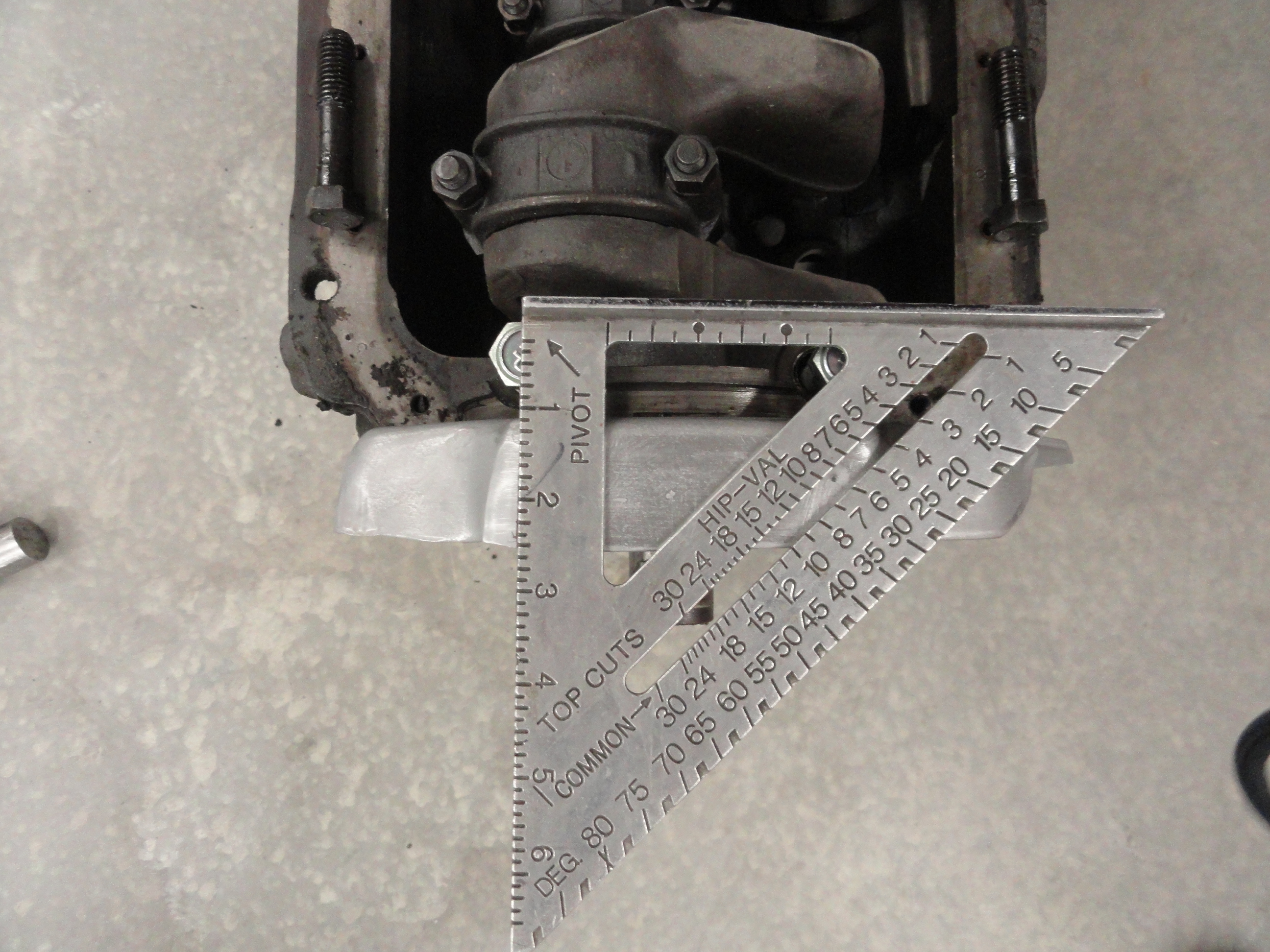

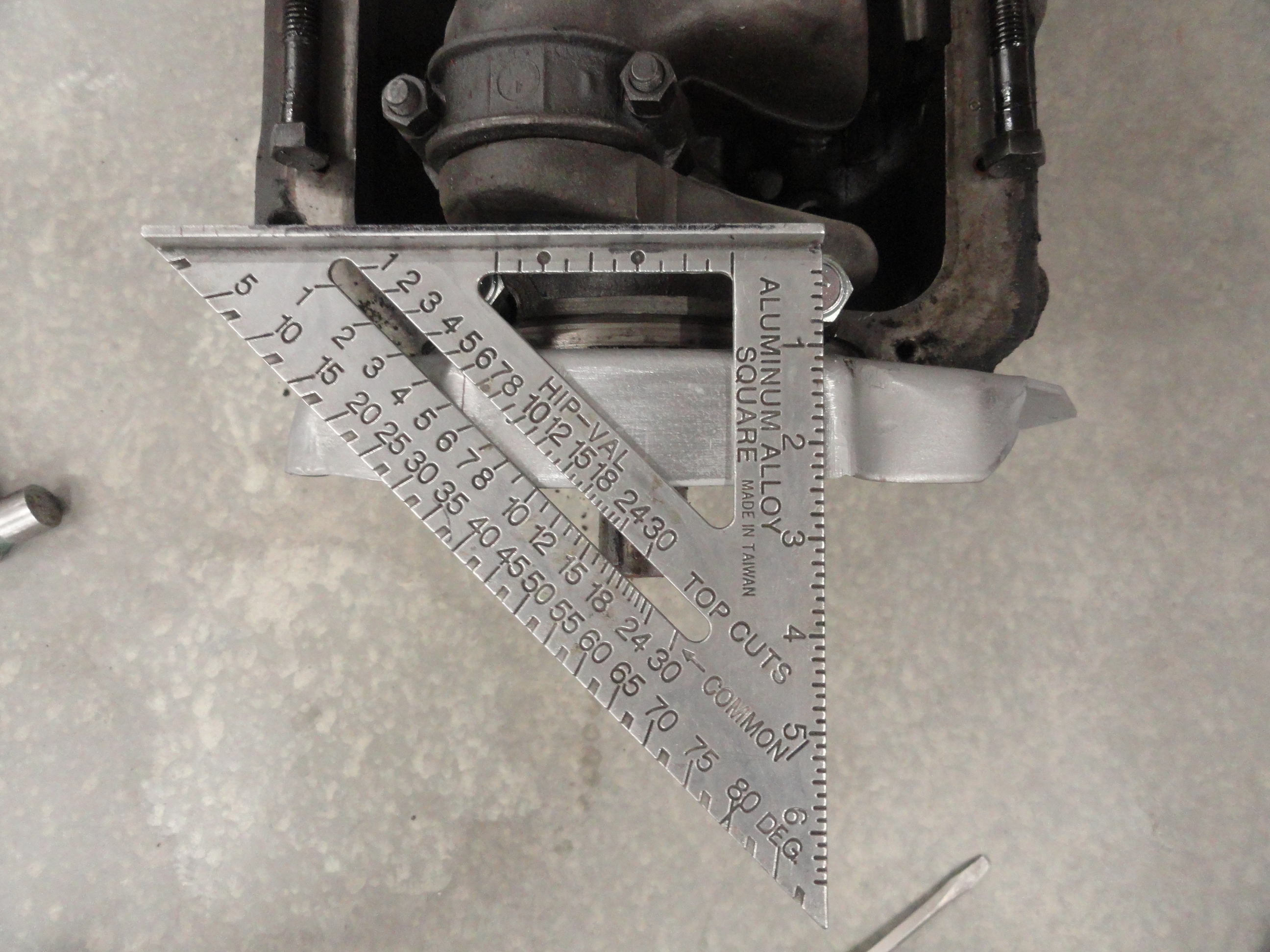
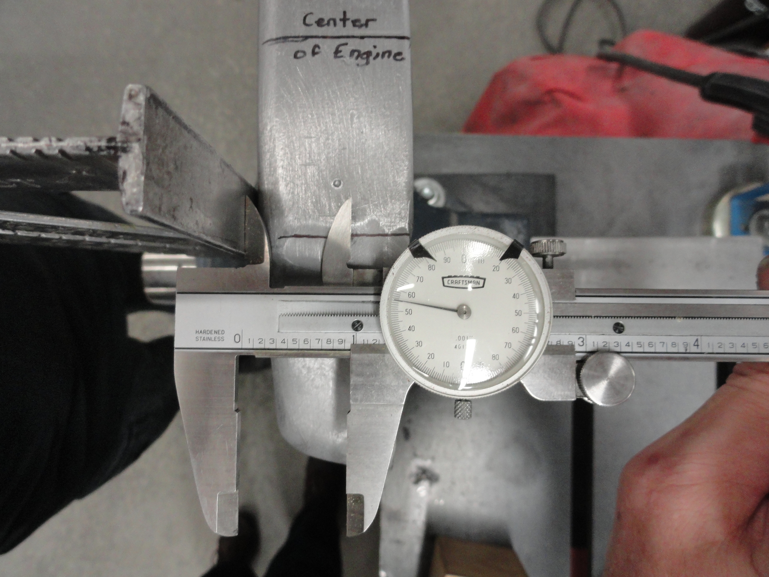
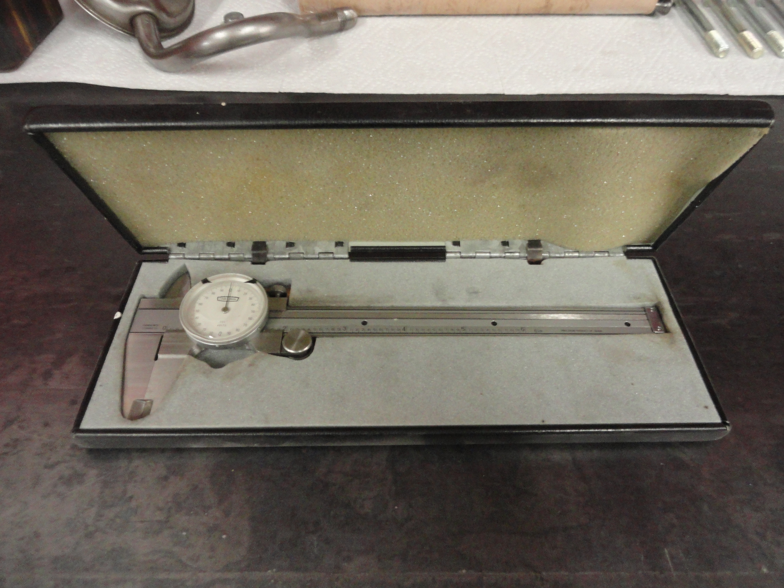
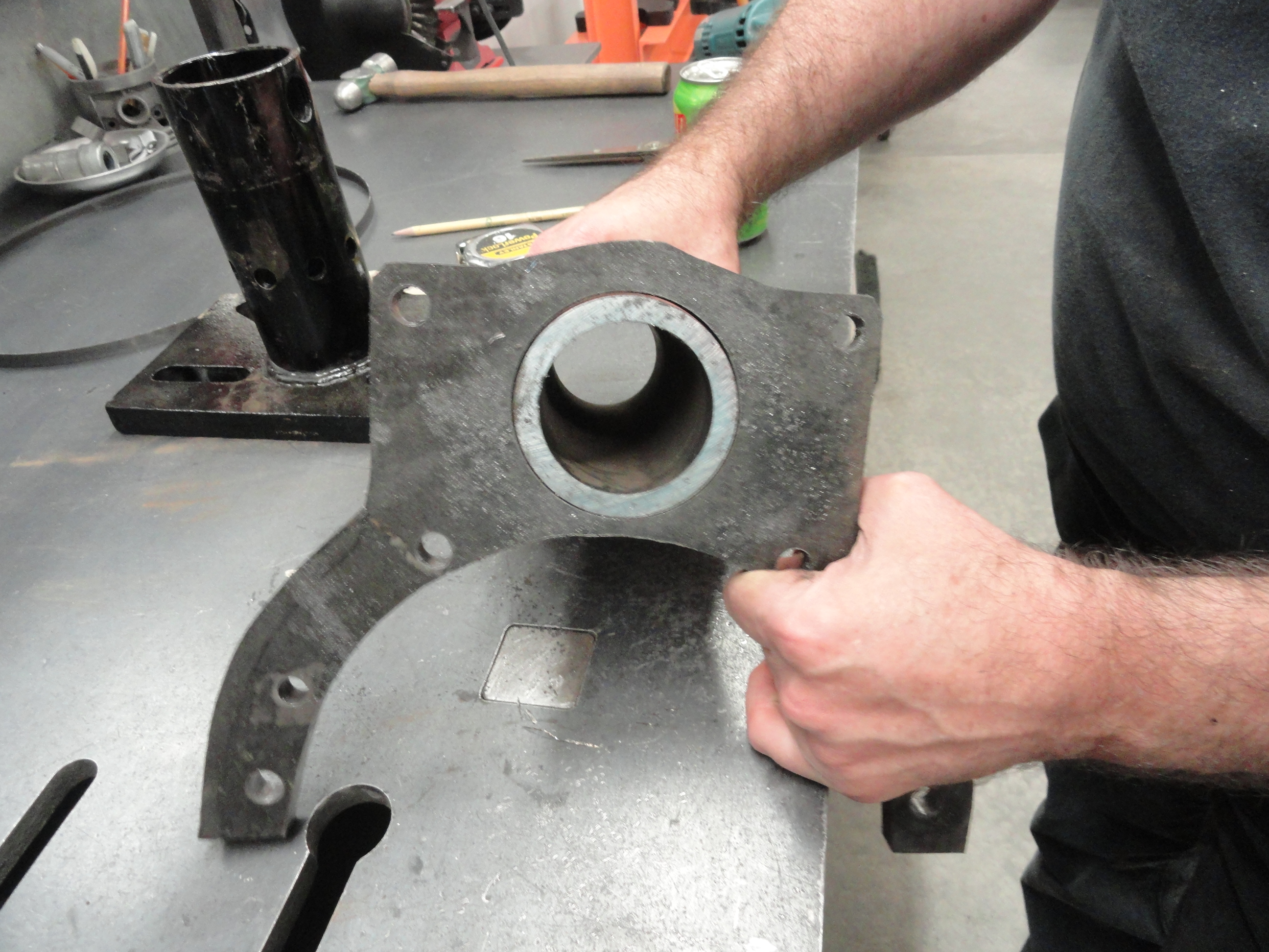
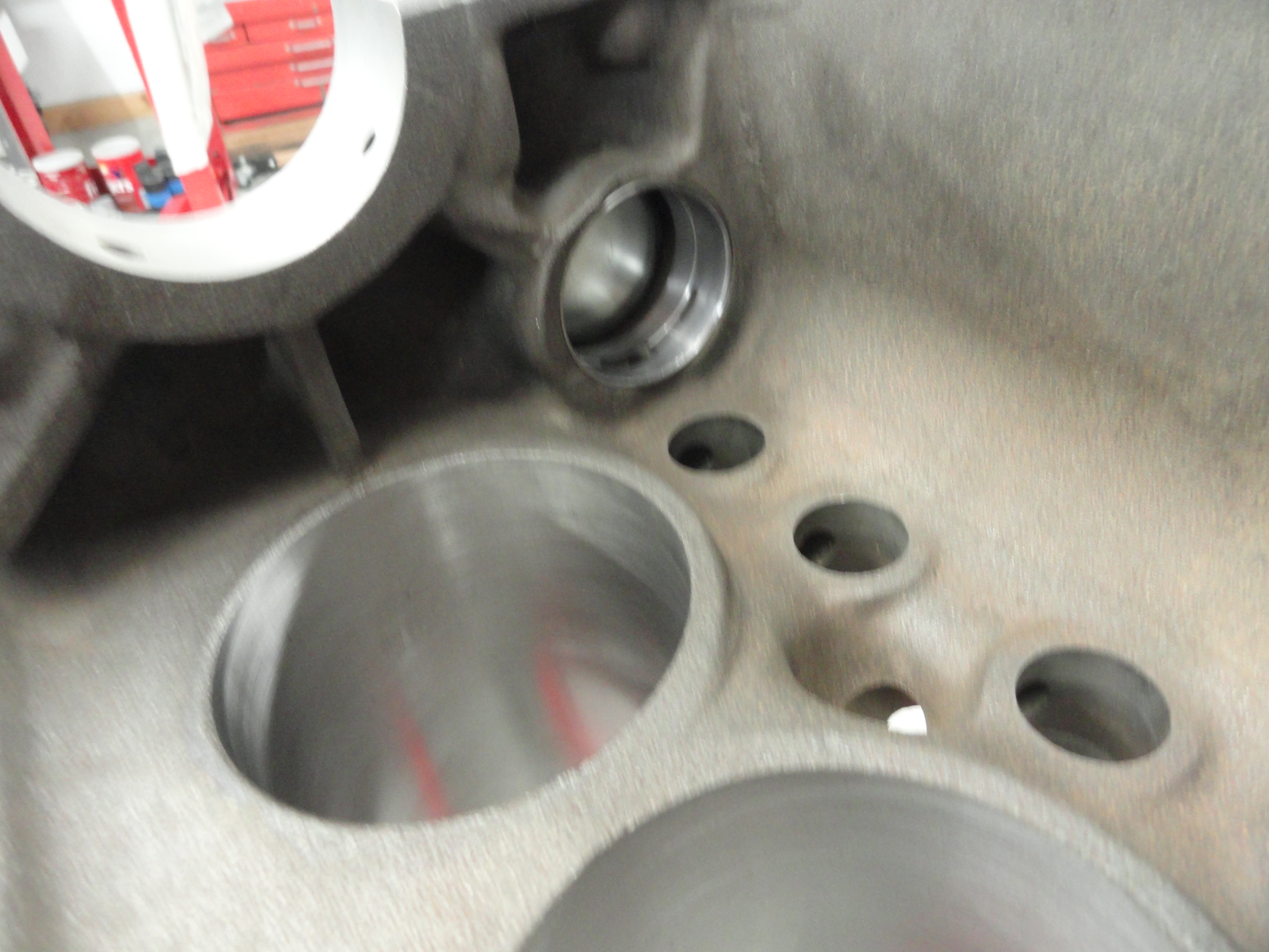
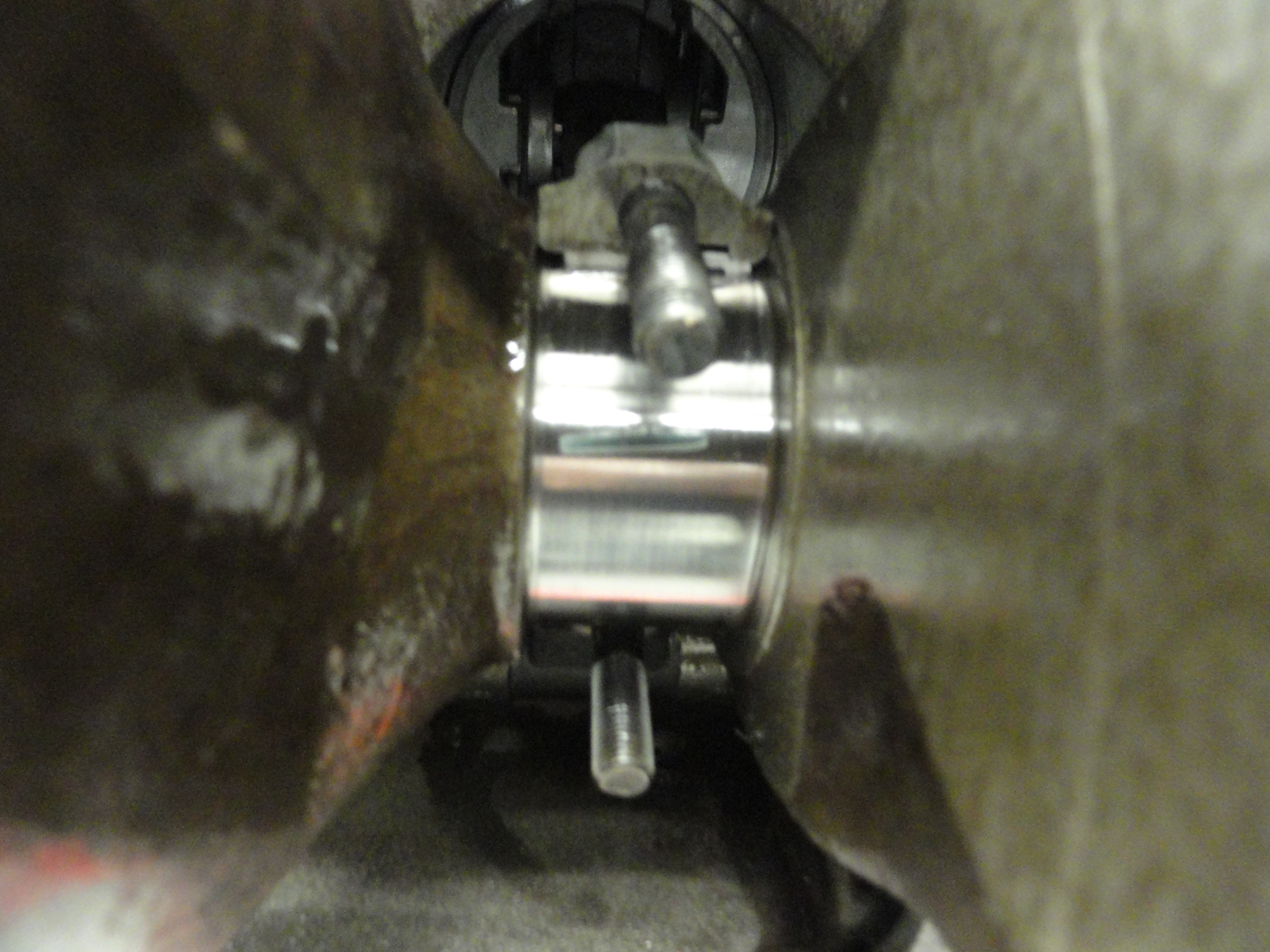
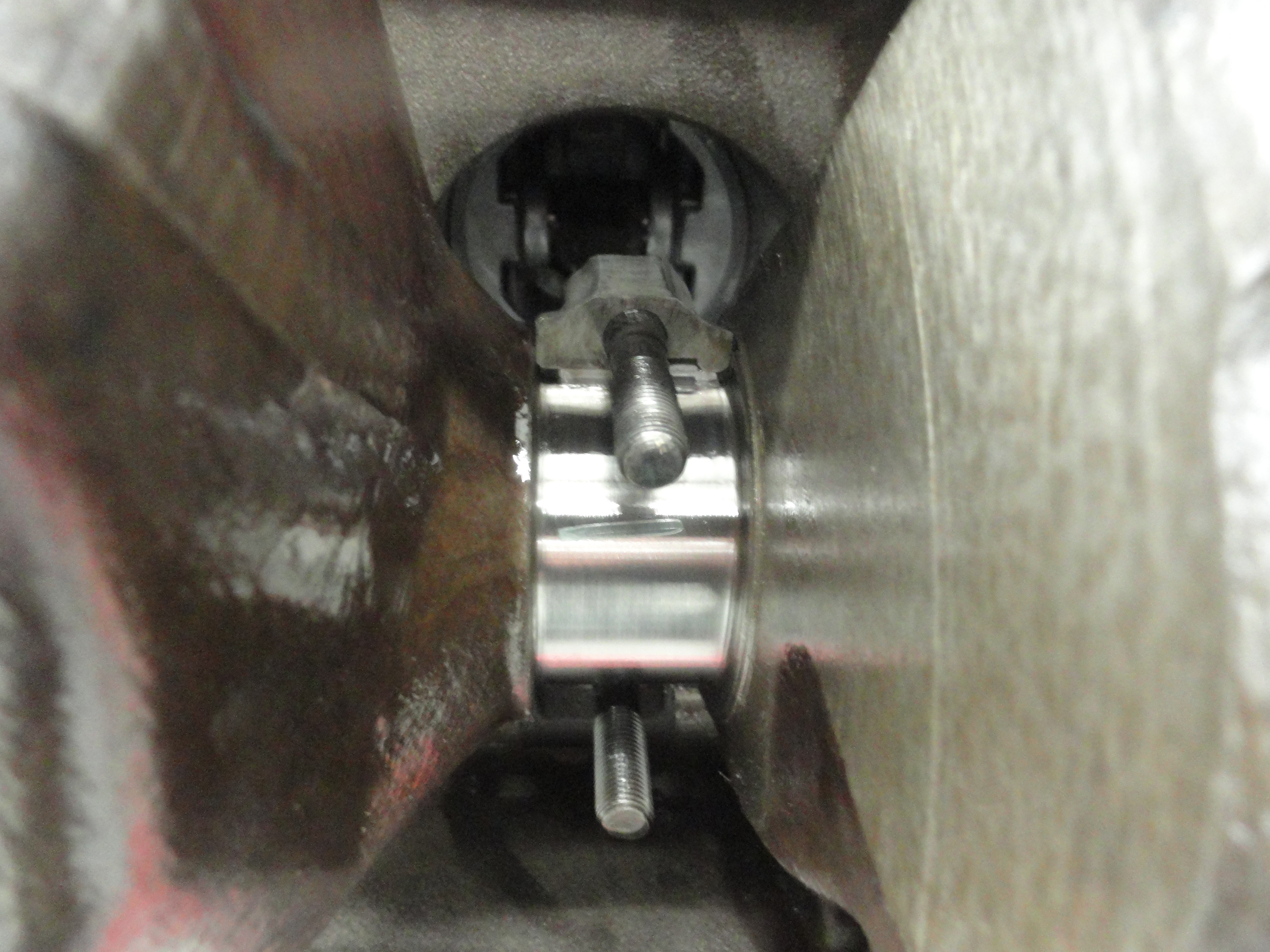
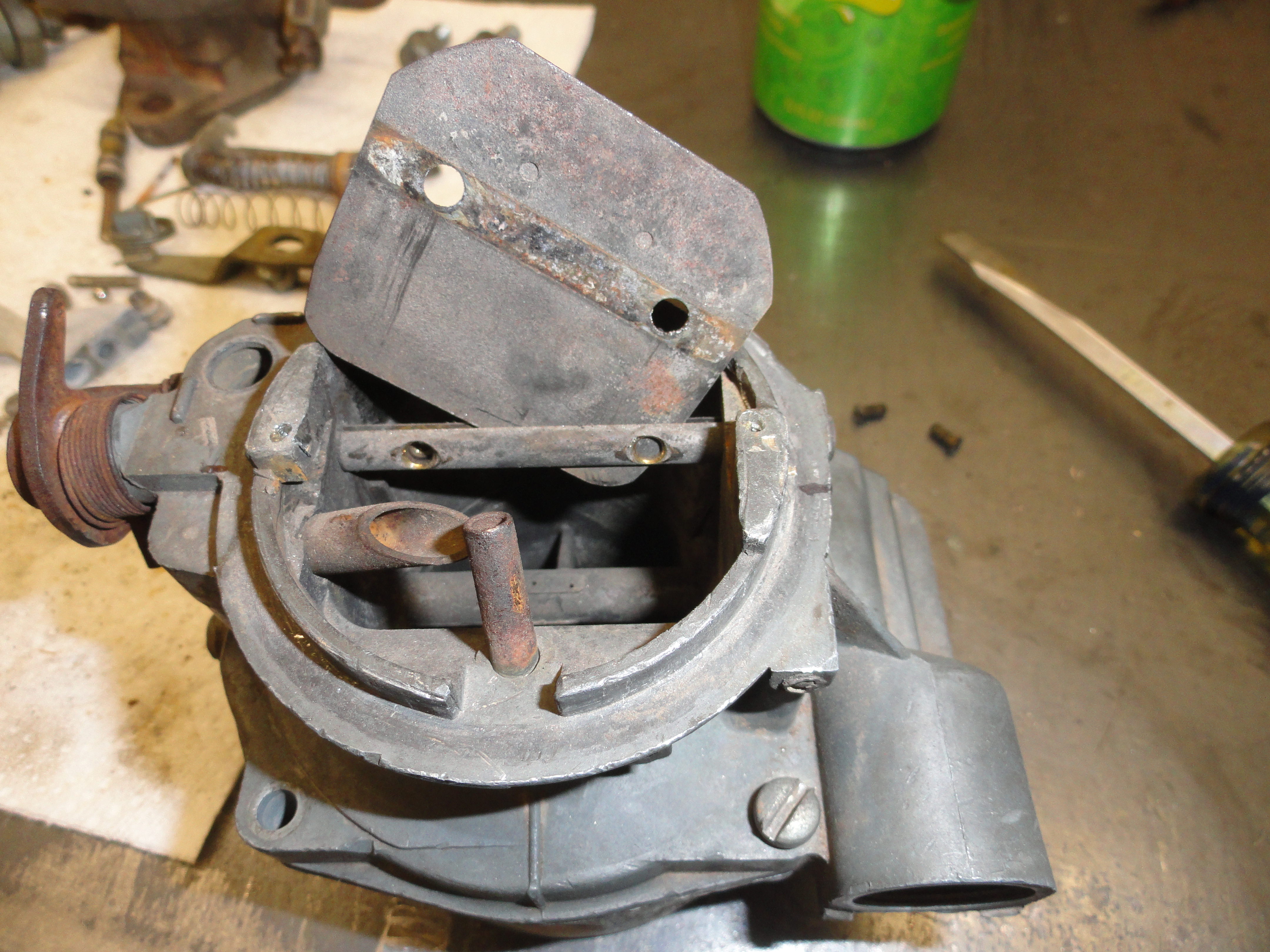
The placement on these holes is pretty important. It aligns the engine left to right on the frame so it MUST be centered to the center of the engines crankshaft. To do this, we put the plate back on the engine temporarily and measure from the crankshafts cap bolts to find the center of the plate. To do this we remove the front crankshaft cap bolts and replace them with longer ones that we can screw in and have the head of the bolt high enough to grab the edge of the T-Square. This allows us to get the T-Square straight and even. Transfer the center of the bolts head to the plate with a thin sharpie. Turn the T-Square over and do the same on the other side. Measure very exacting between your two lines and that is the very center of the engine. Mark the center with a thin sharpie (not shown). From the edge of the plate using the T-Square as the guide to compensate for its curve, measure using a Caliper to .955 inches. Put a mark where it intersects with the engine cap line. Do this on both sides. In the picture we are using the upper part of the Caliper. Now draw a line all the way across the plate to each mark you just made.
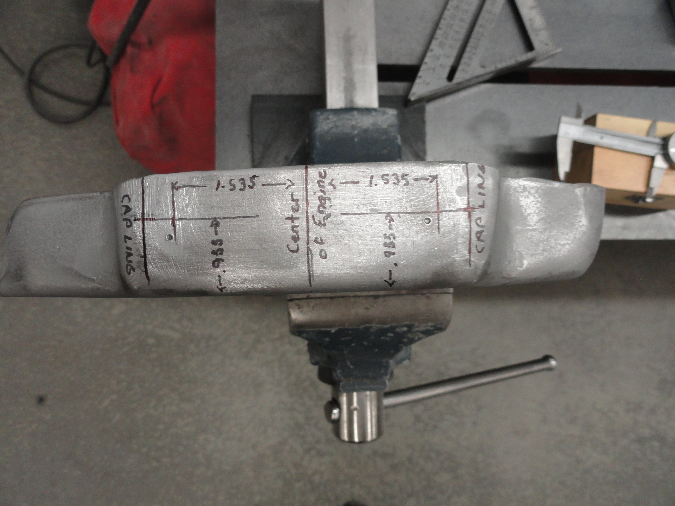
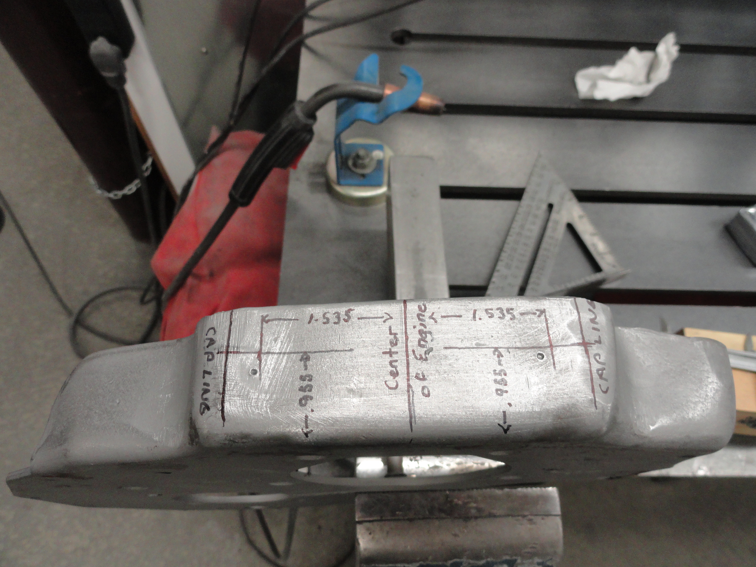
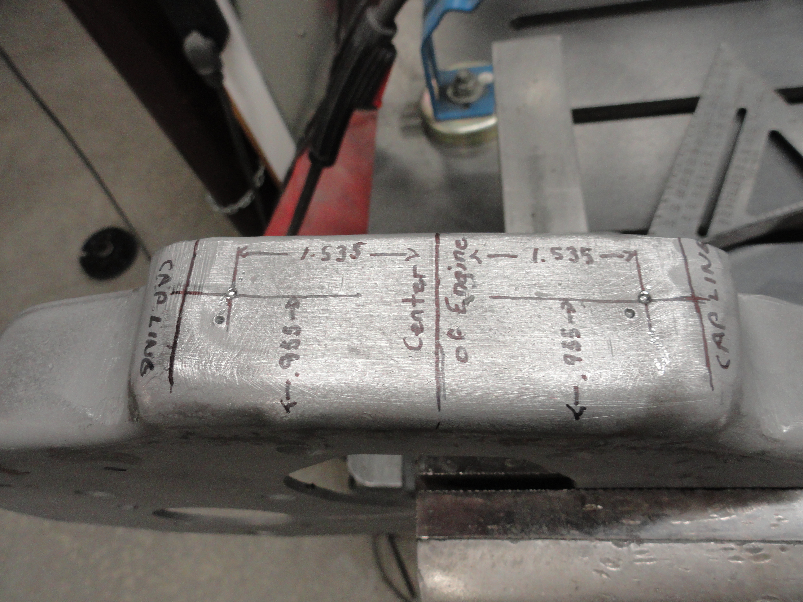
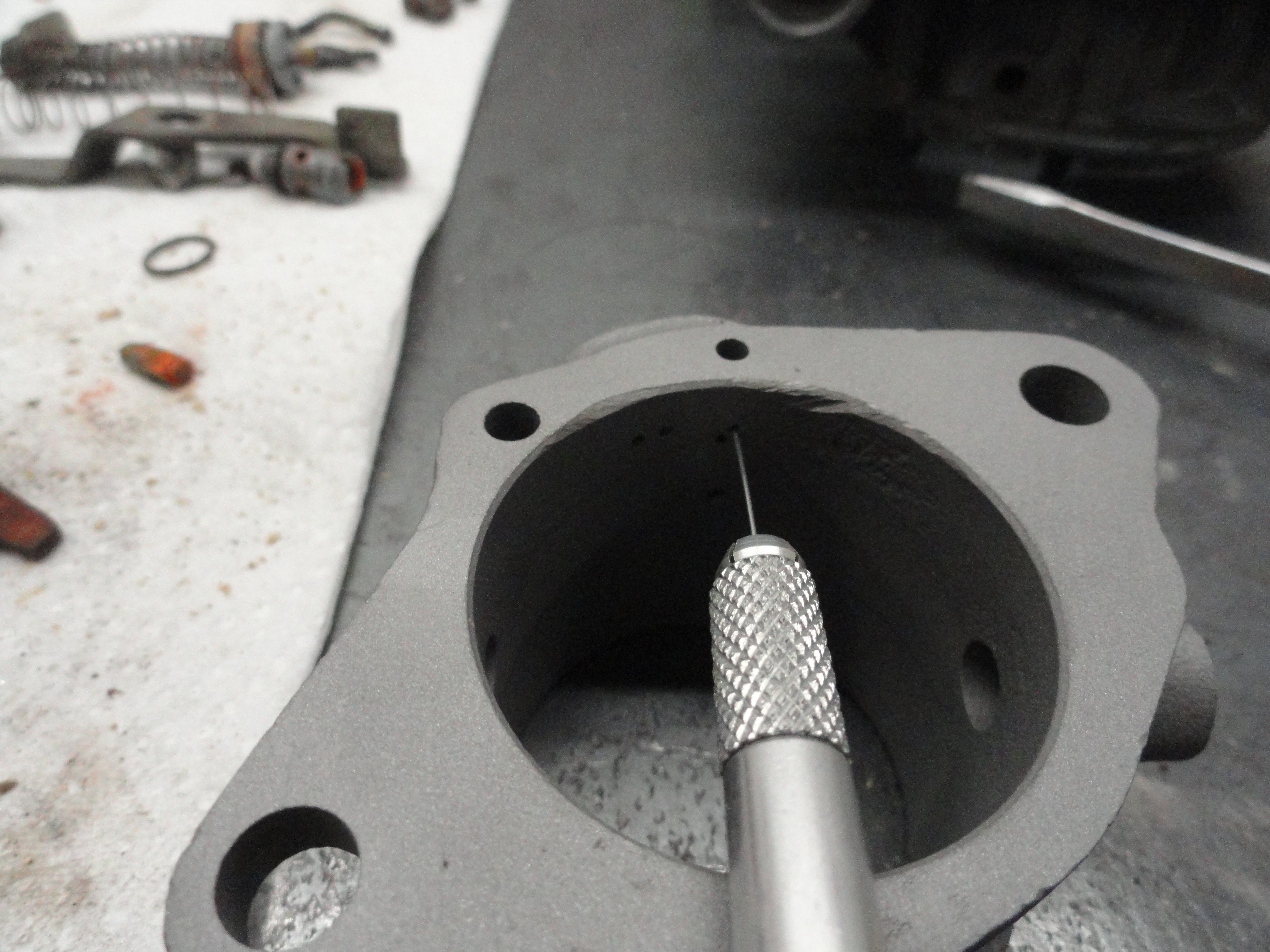
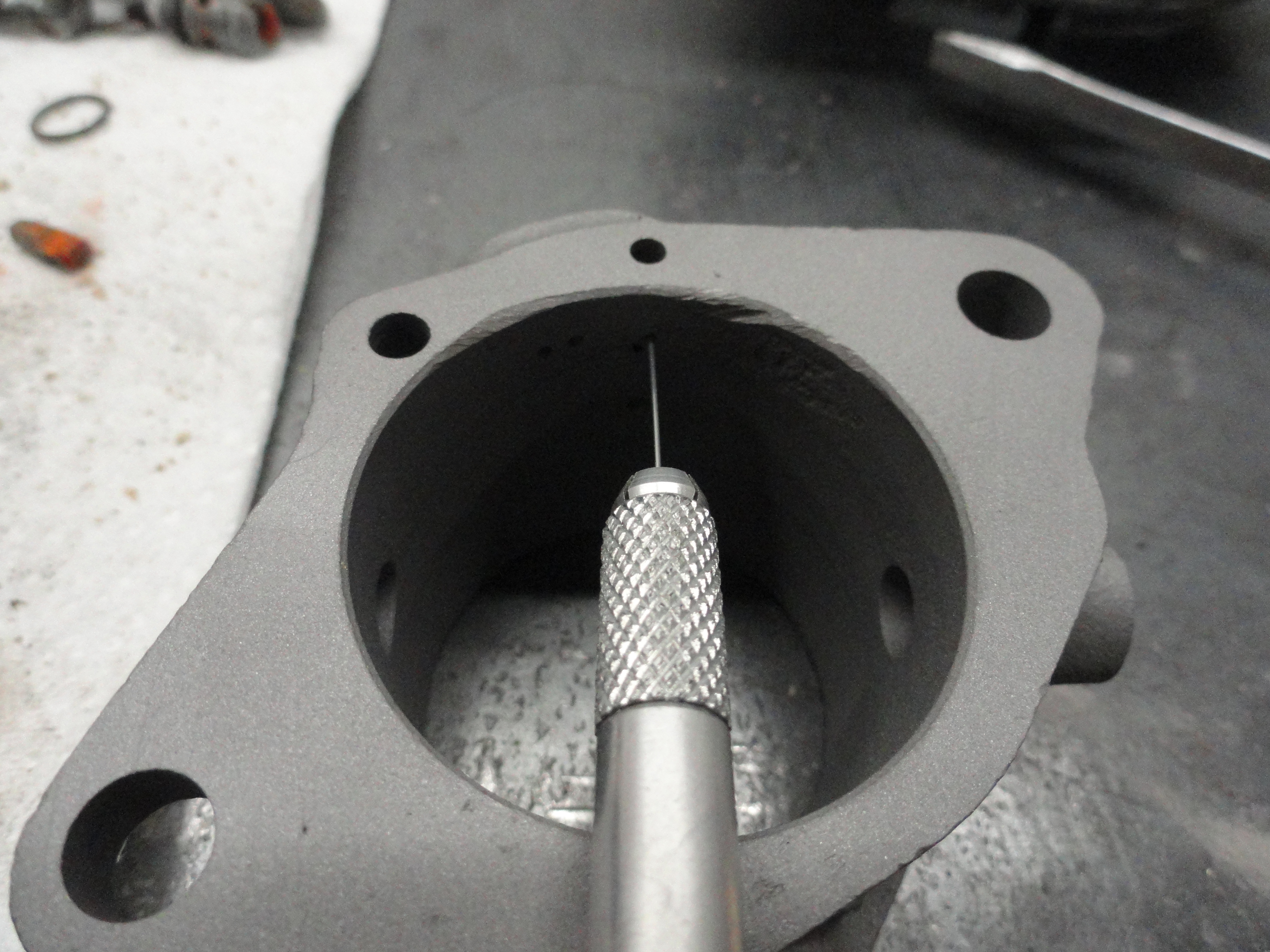
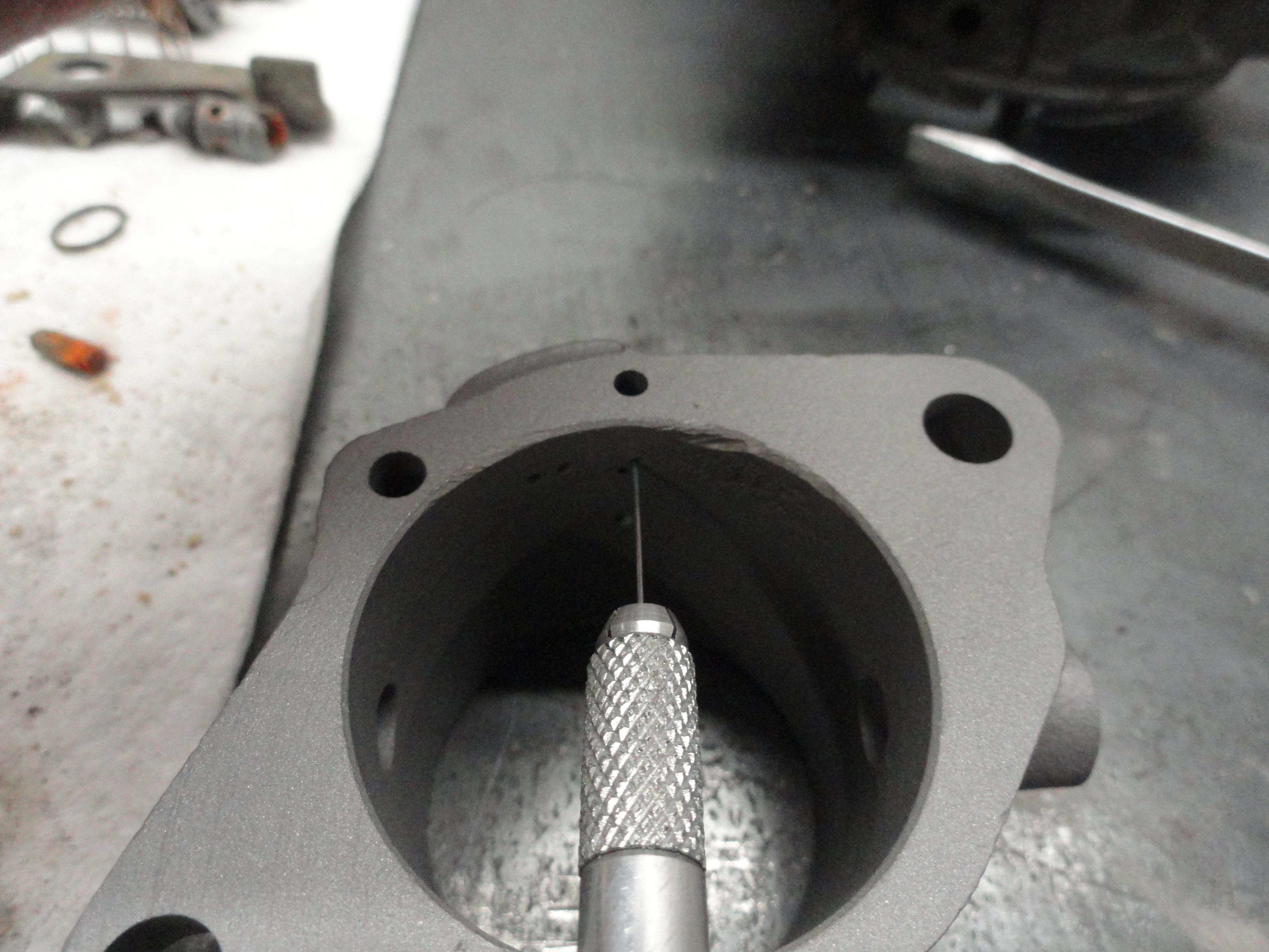
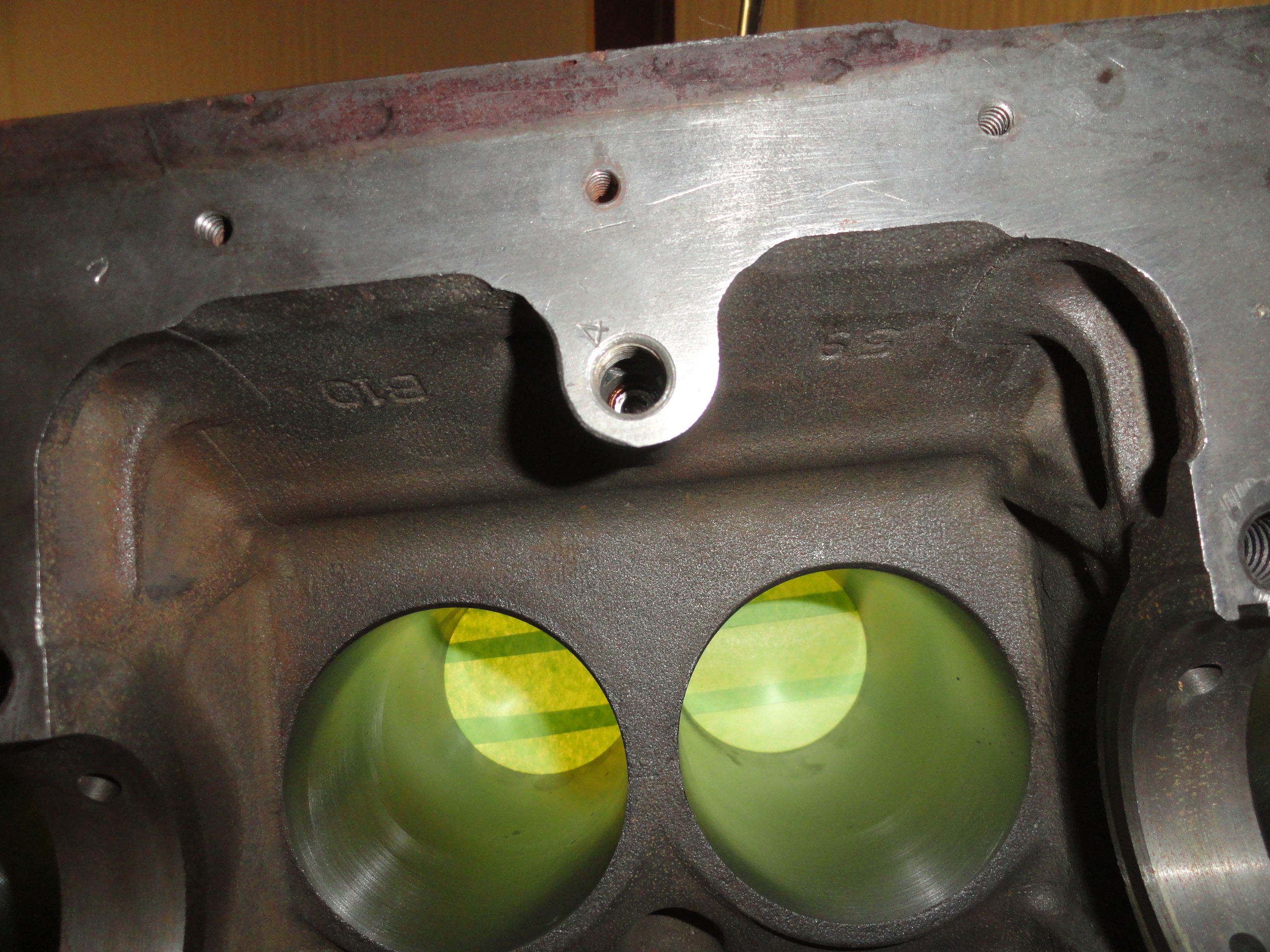
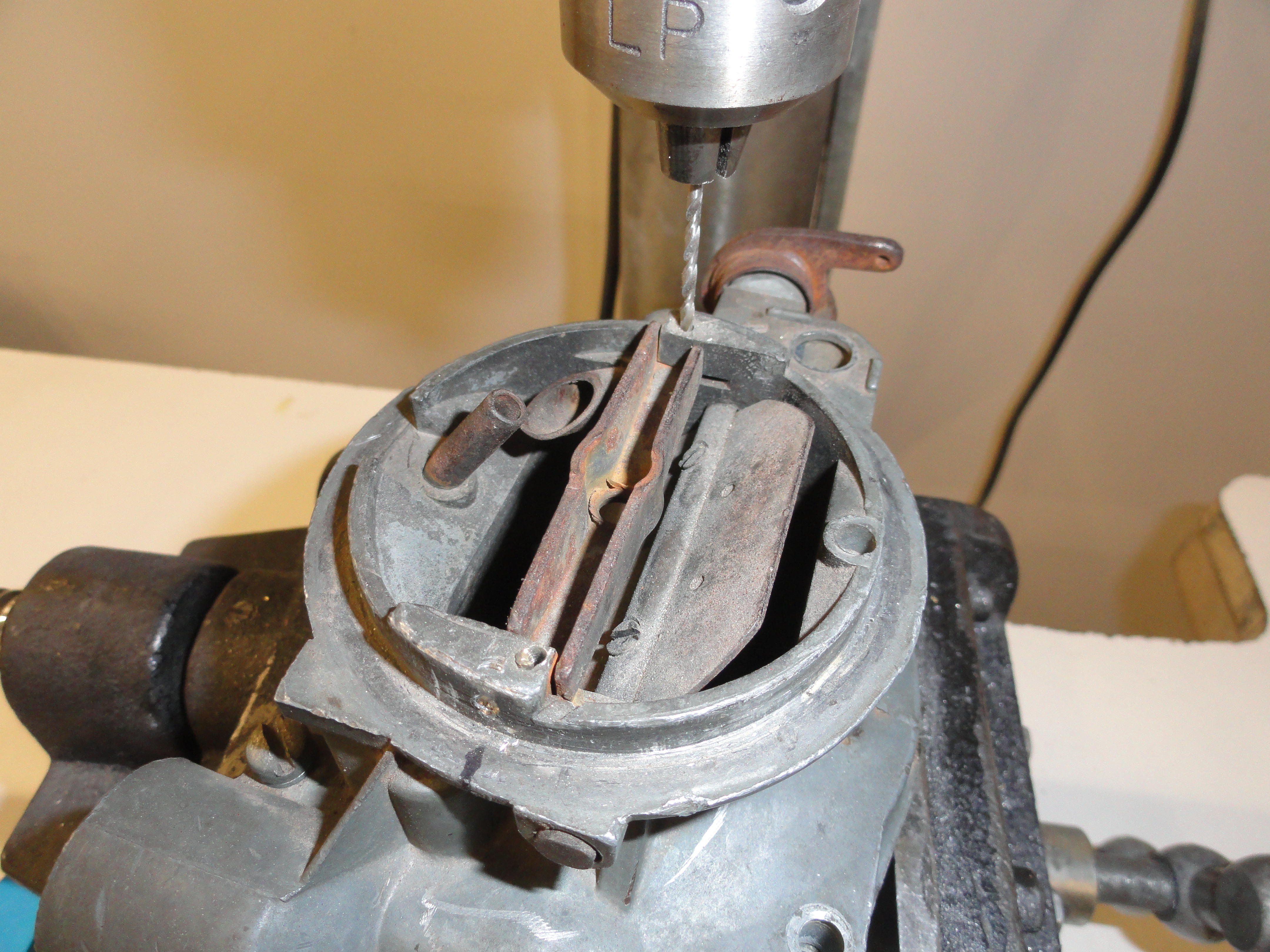
From the engine center line, we need to place a mark at exactly 1.535 inches to the left of the centerline AND again to the right of the center line. This is the 3.070 inches we need between the center of the holes. Never mind those erroneous dimples that are there, it was from an earlier trial. So happens, I have a good friend in Washington State who lives and breathes these engines and he was so kind as to send me a series of pictures to properly align these holes. He uses a Chevy original plate that already had the holes drilled in the right place. You do not want to use the edge of the plate as a reference for anything because they differ enough to make them unreliable. Always measure from the face using a T-Square. It's a good idea to dimple the centerline as shown just for future reference. Dimple the cross line intersecting between your 3.070 inches and your .955 inches for drilling. Use a 29/64" drill bit. I recommend using about a 3/8" bit to start with and move up so as not to have problems with the bit wandering.
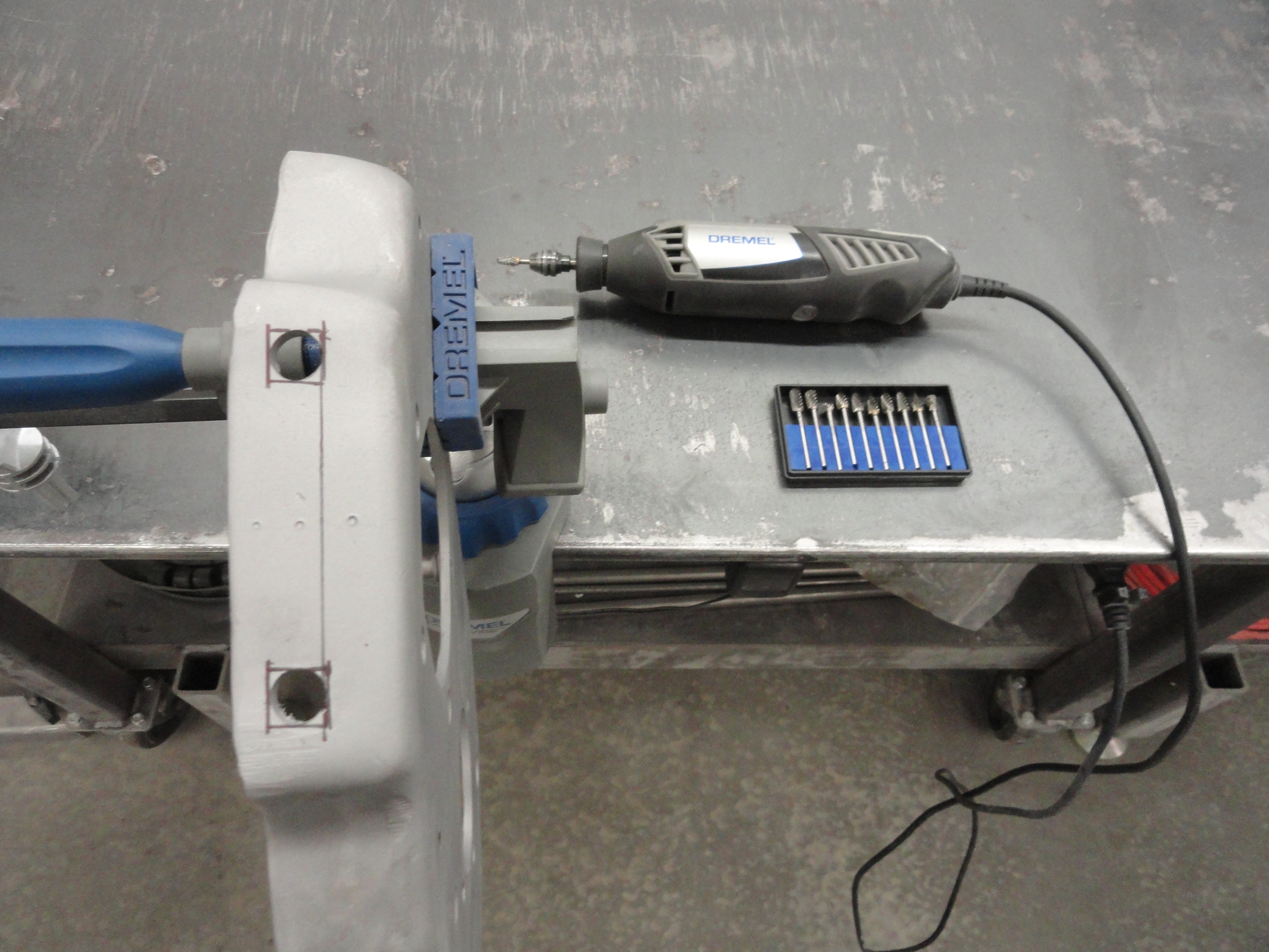
Once you have your holes drilled, we need to make them square. This is rather hard to do for a home garage mechanic like myself, but I use a Dremel tool with a Carbide Rasp and it gets the job done. The slower you go, the nicer it turns out. Use the proper 7/16" Carriage Bolt to check your work. It's just a matter of making the hole that is there, square. That's all there is to it! It is worth mentioning that while you are going to all of this trouble to be 'correct', it makes a lot more sense from a common sense perspective to keep the hole round, weld a 7/16" fine thread Weld Nut to the inside of the Plate, where the Head is in the pictures, and then bolt your engine to the frame from underneath. The reason this is a popular idea is because if you forget to put that Carriage Bolt into that hole before you put the Timing Cover back on, you are in sort of a pickle.
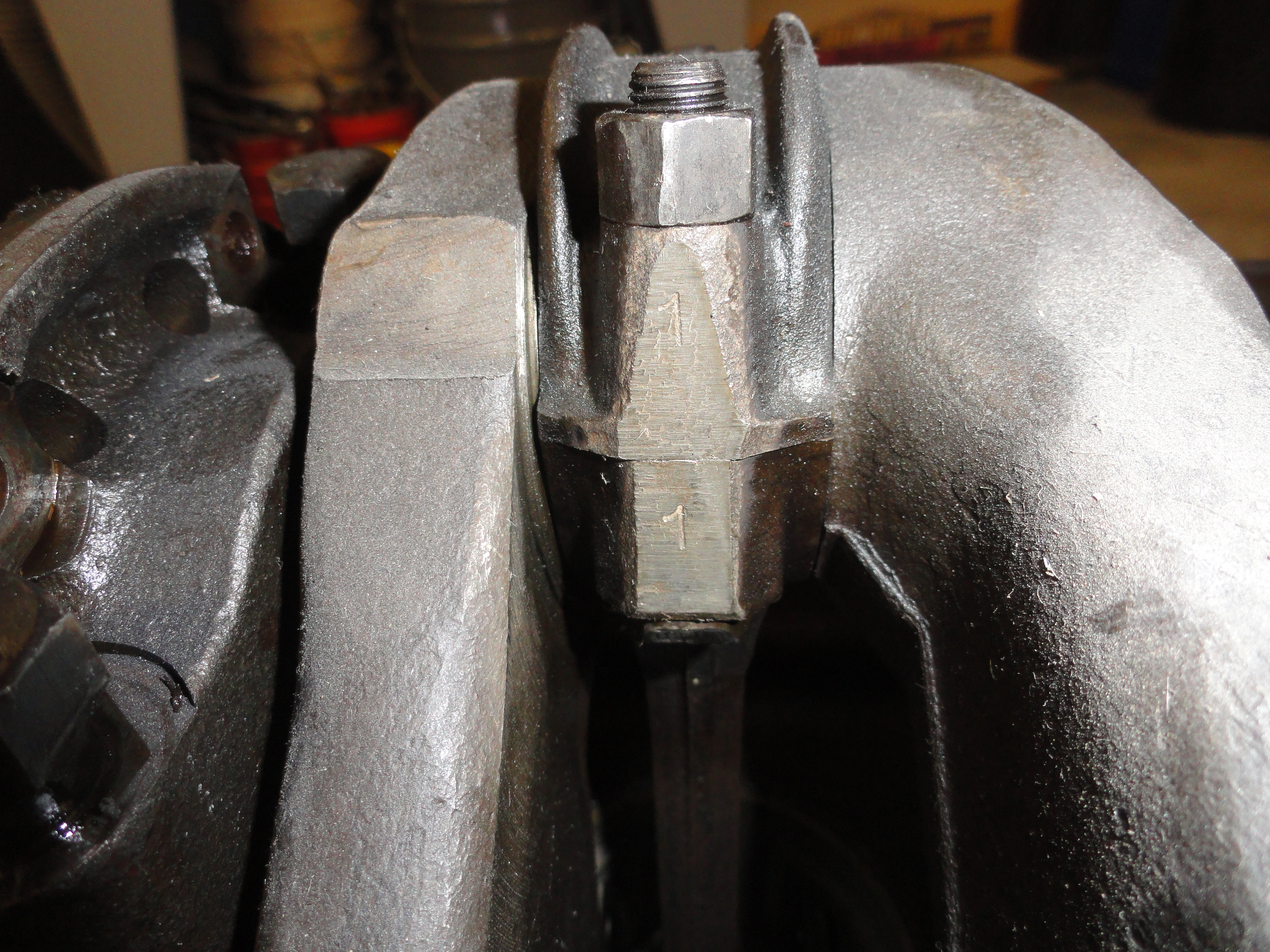
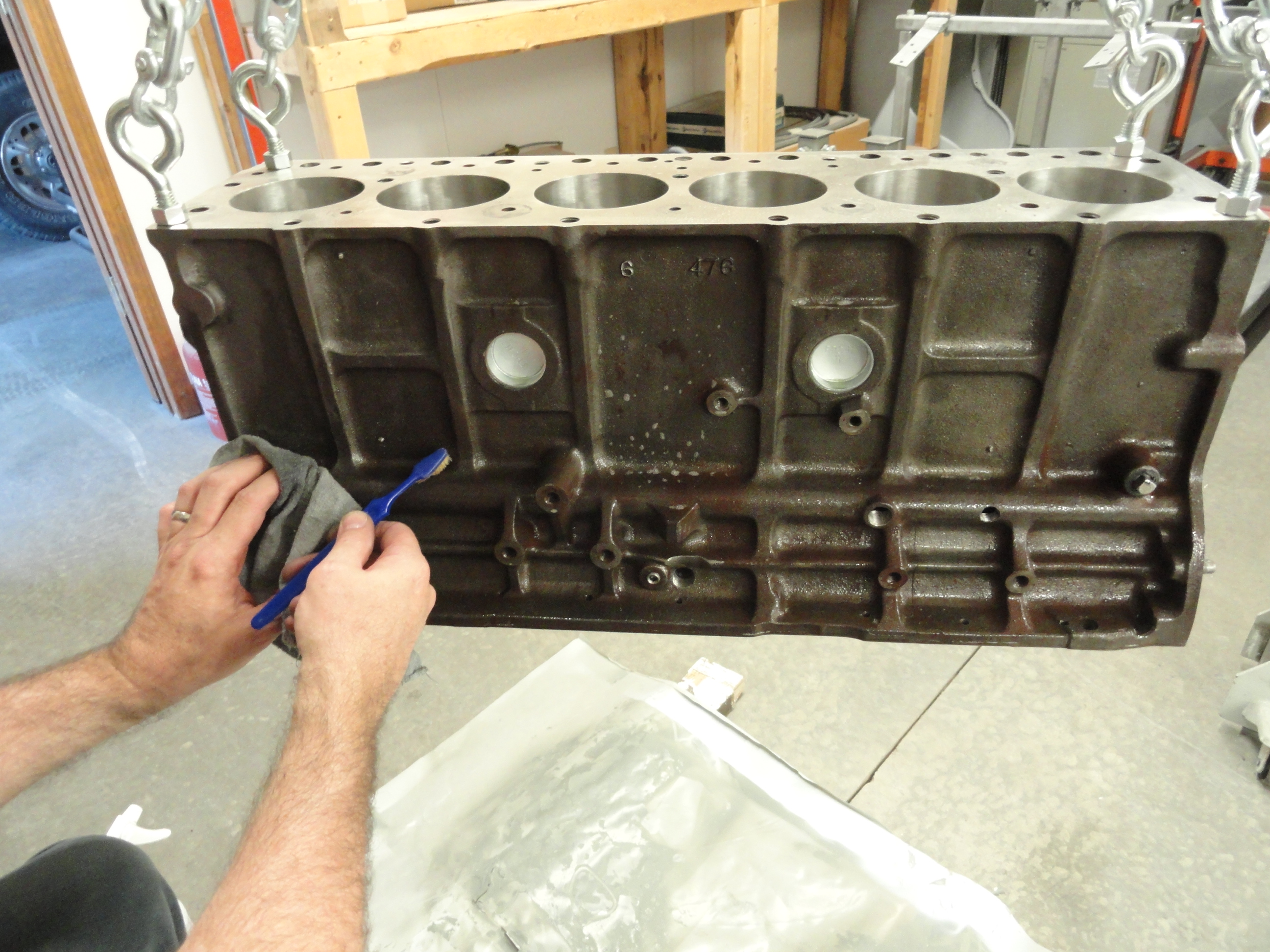
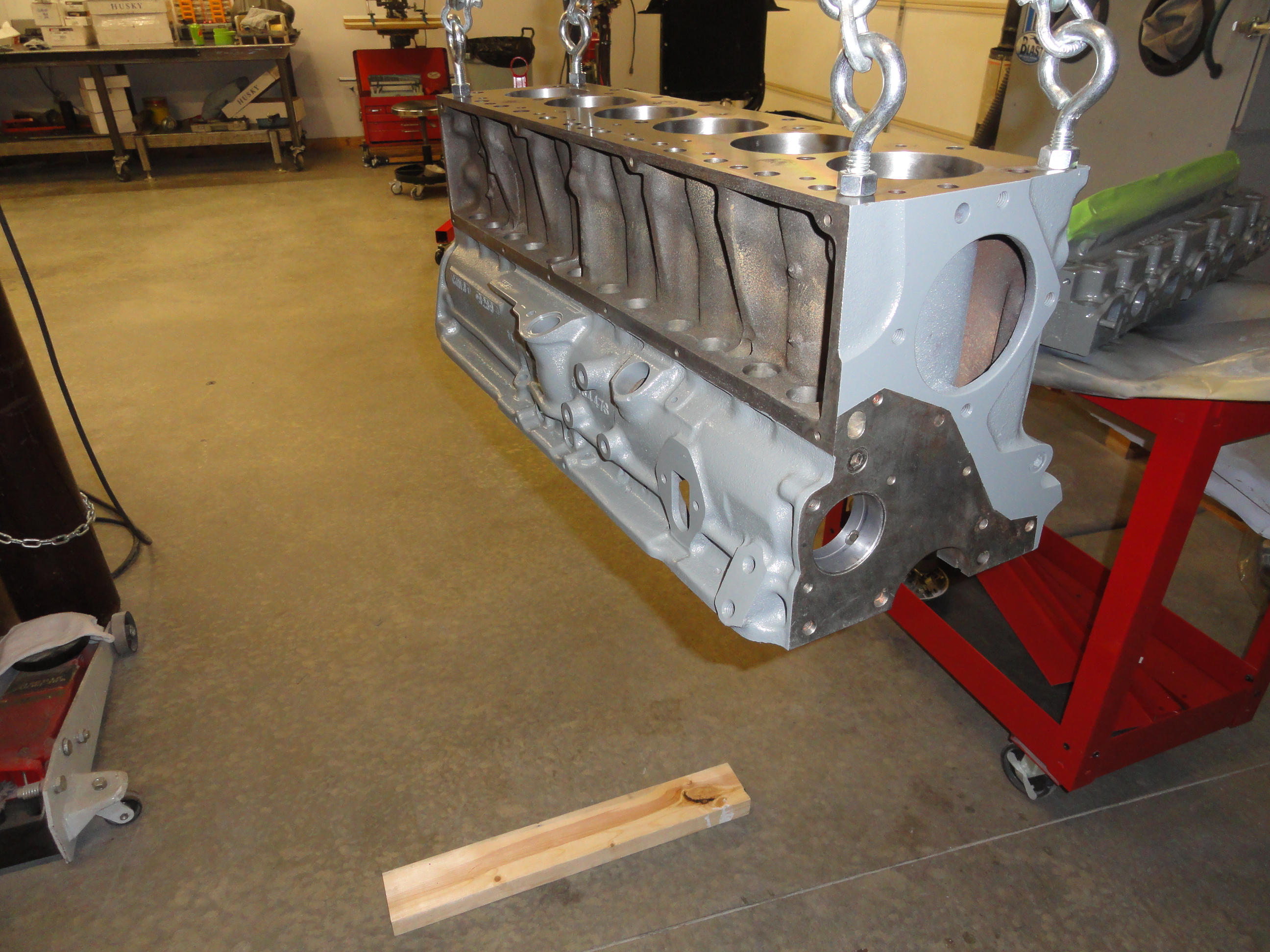
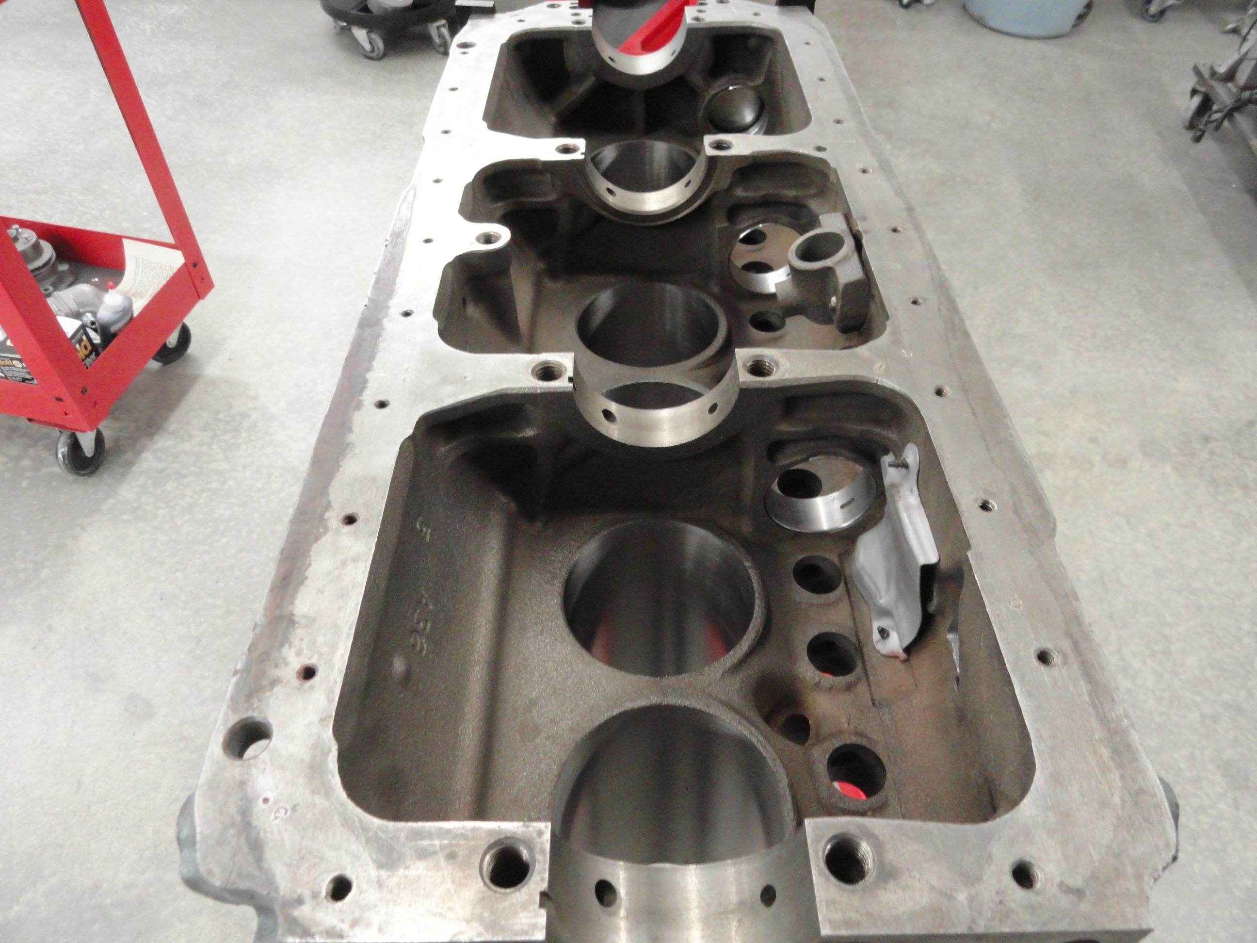
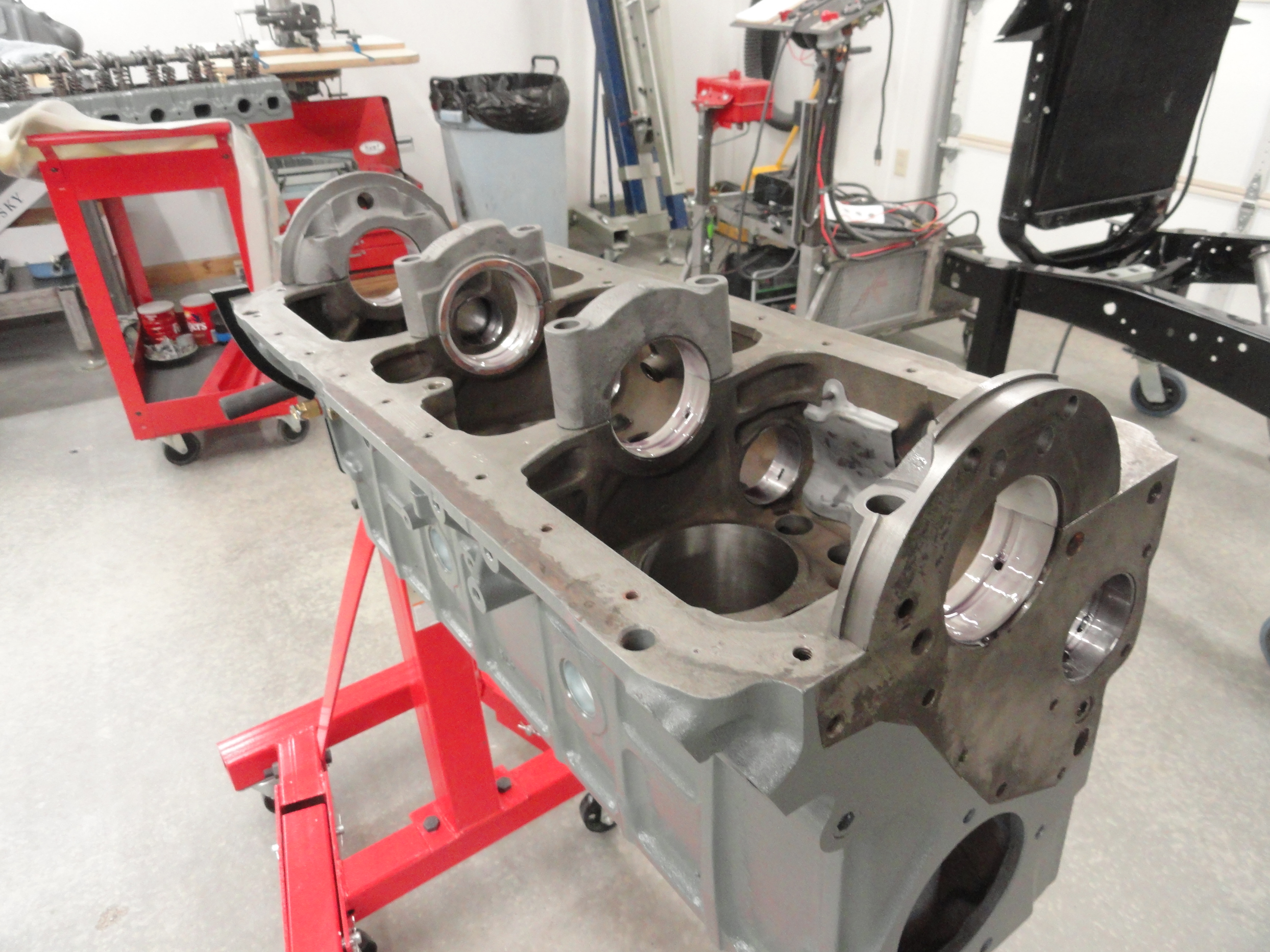
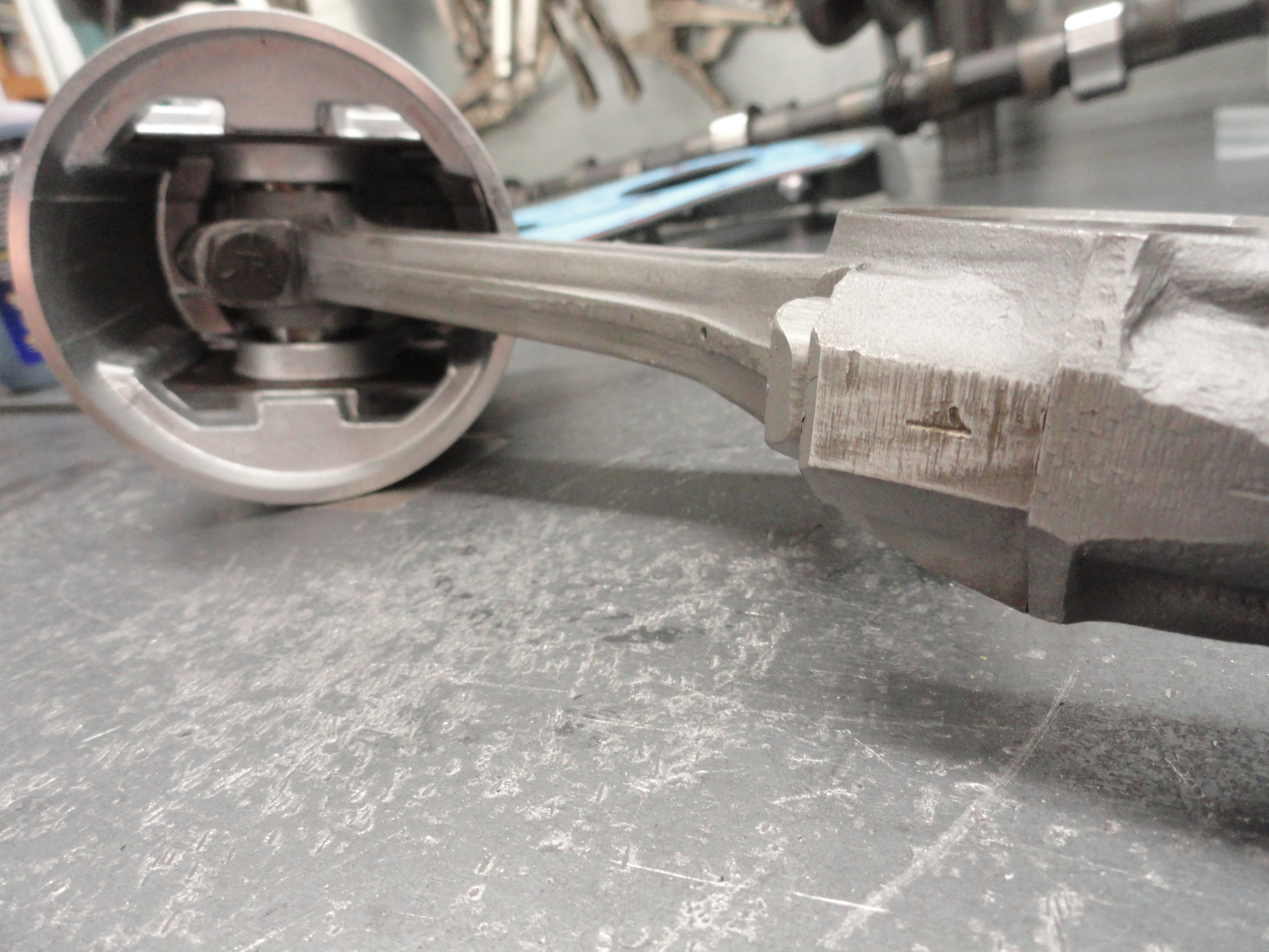
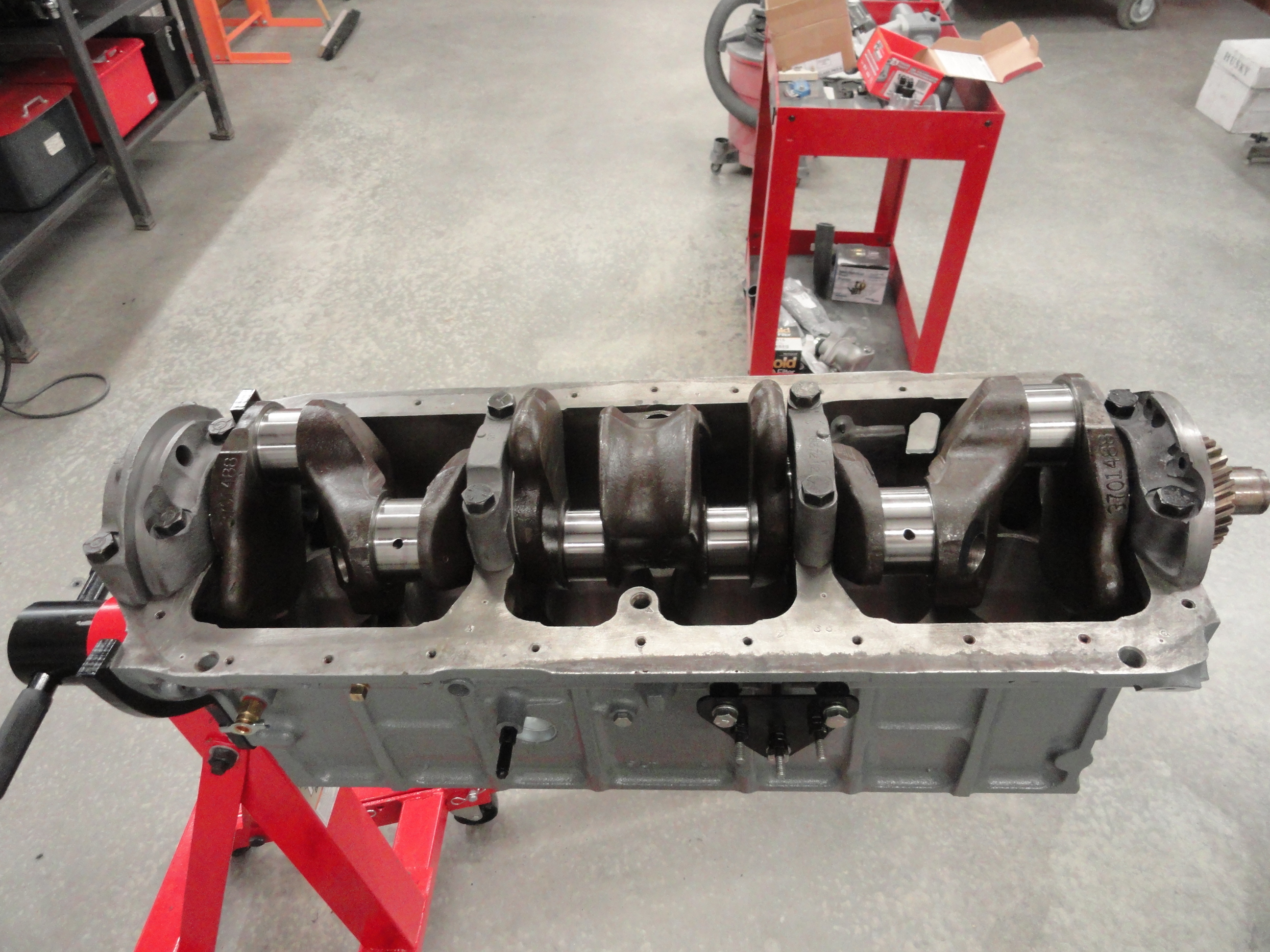
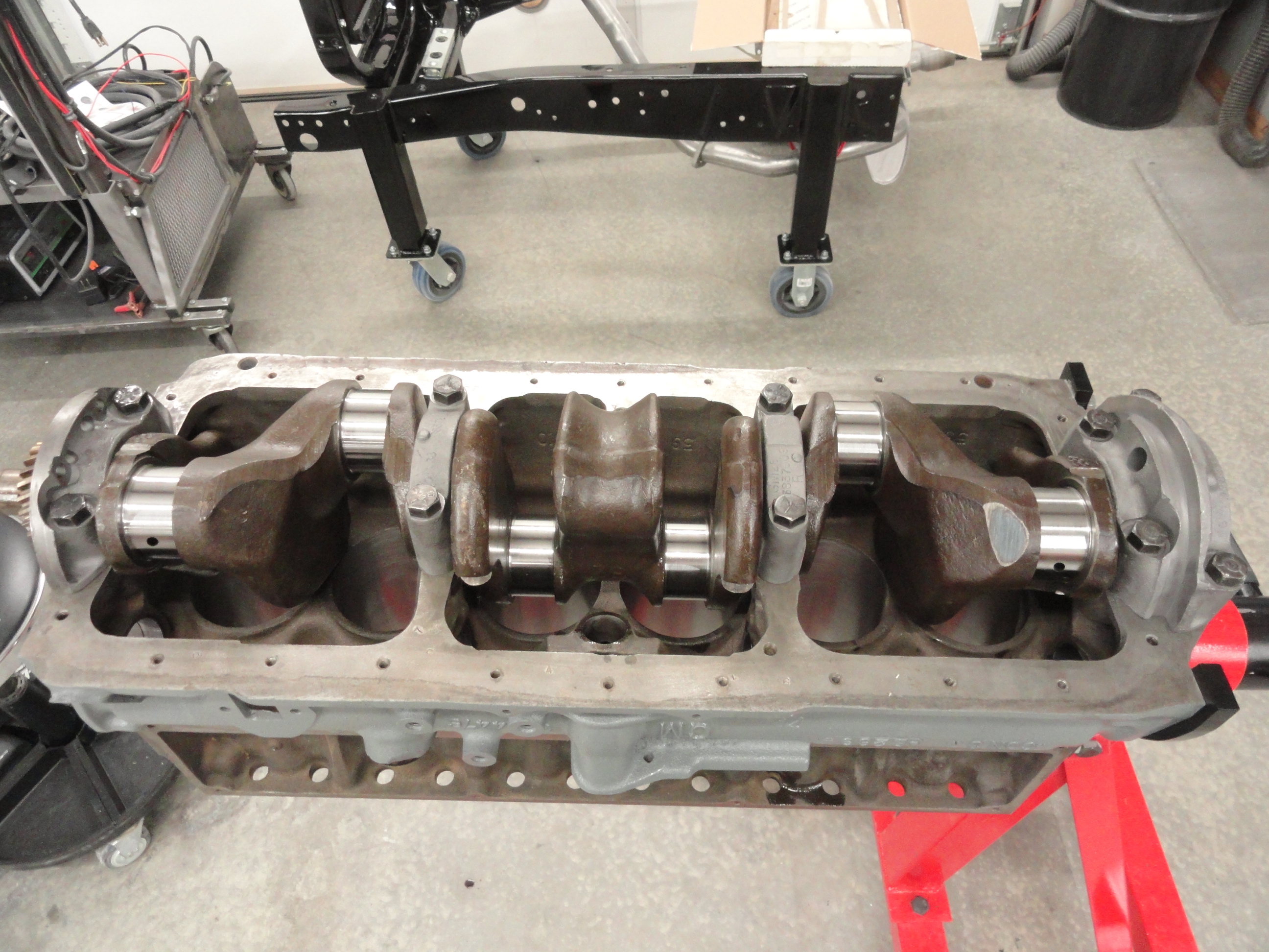
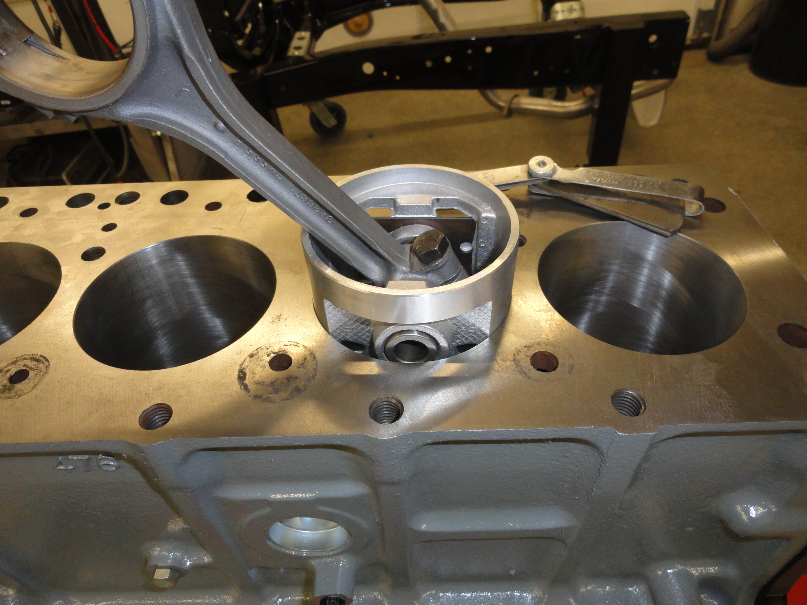
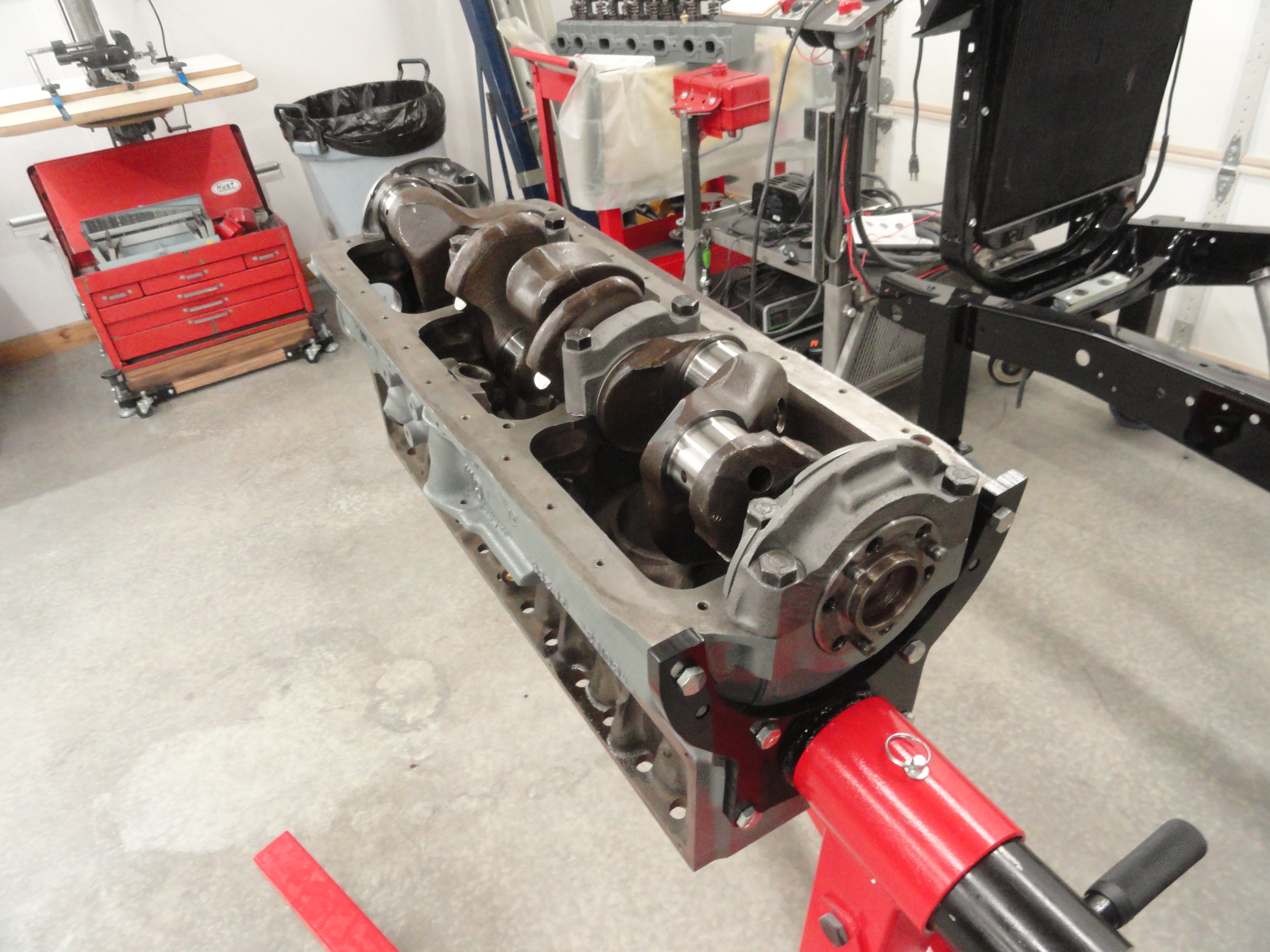
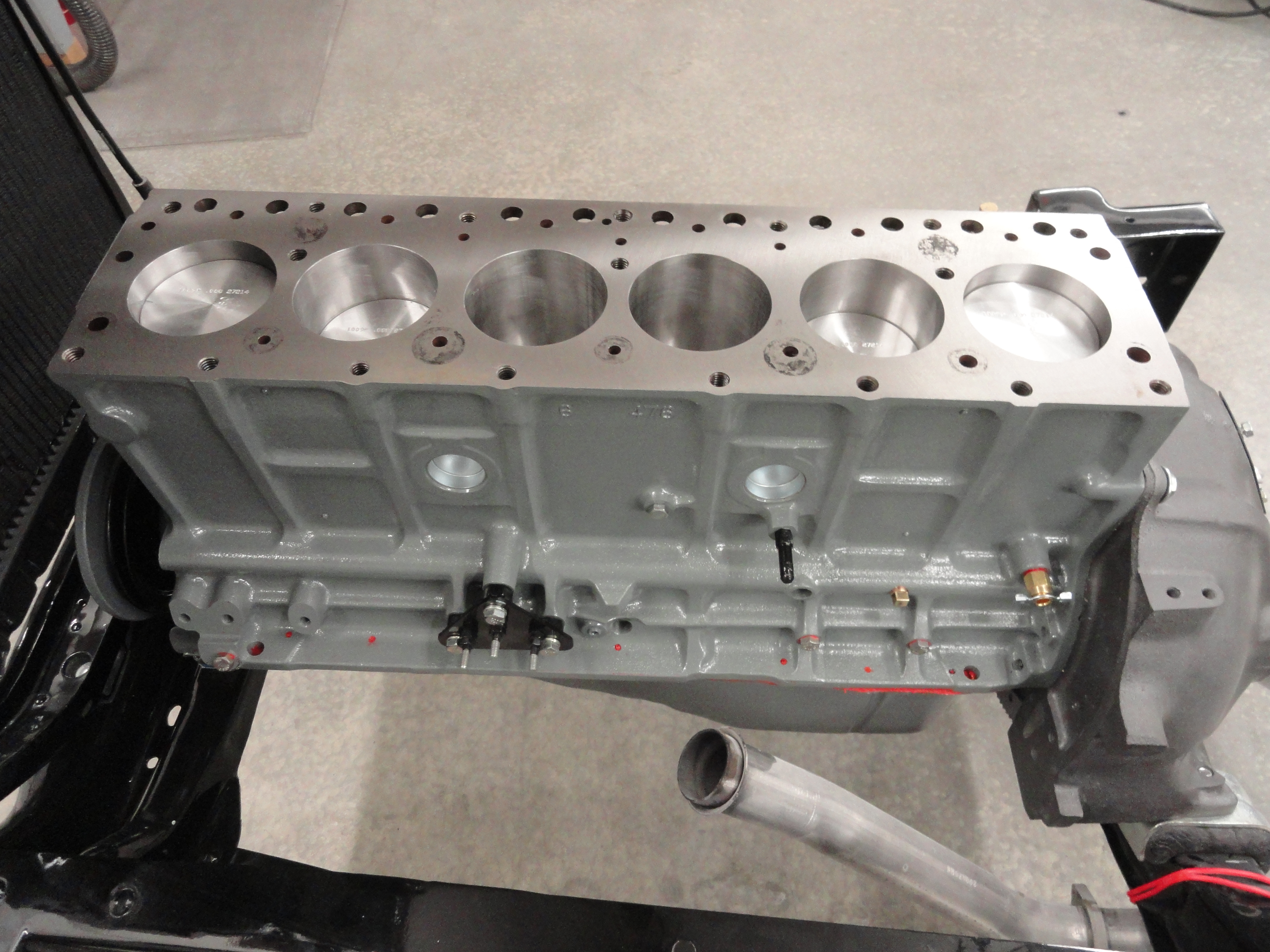
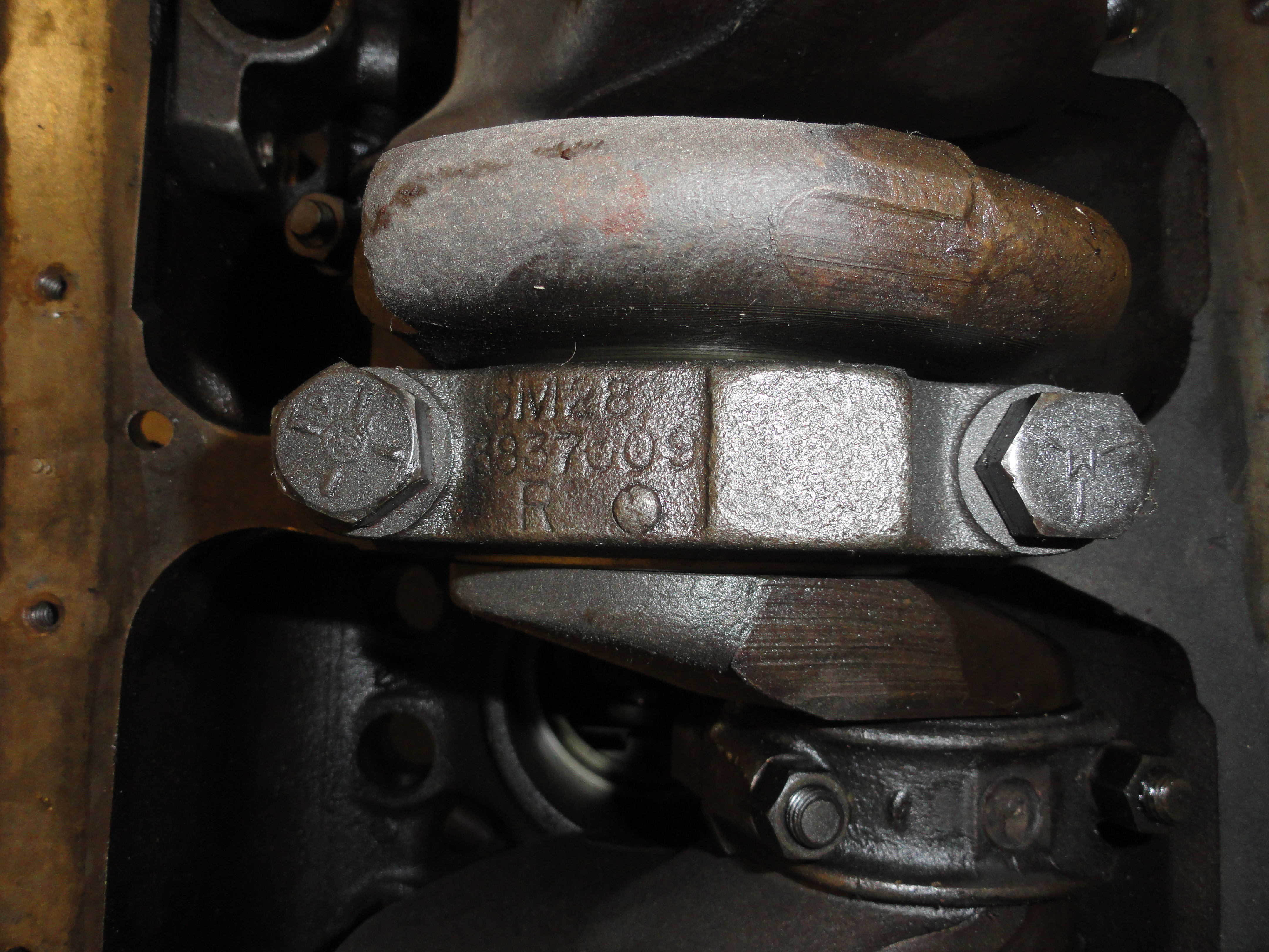
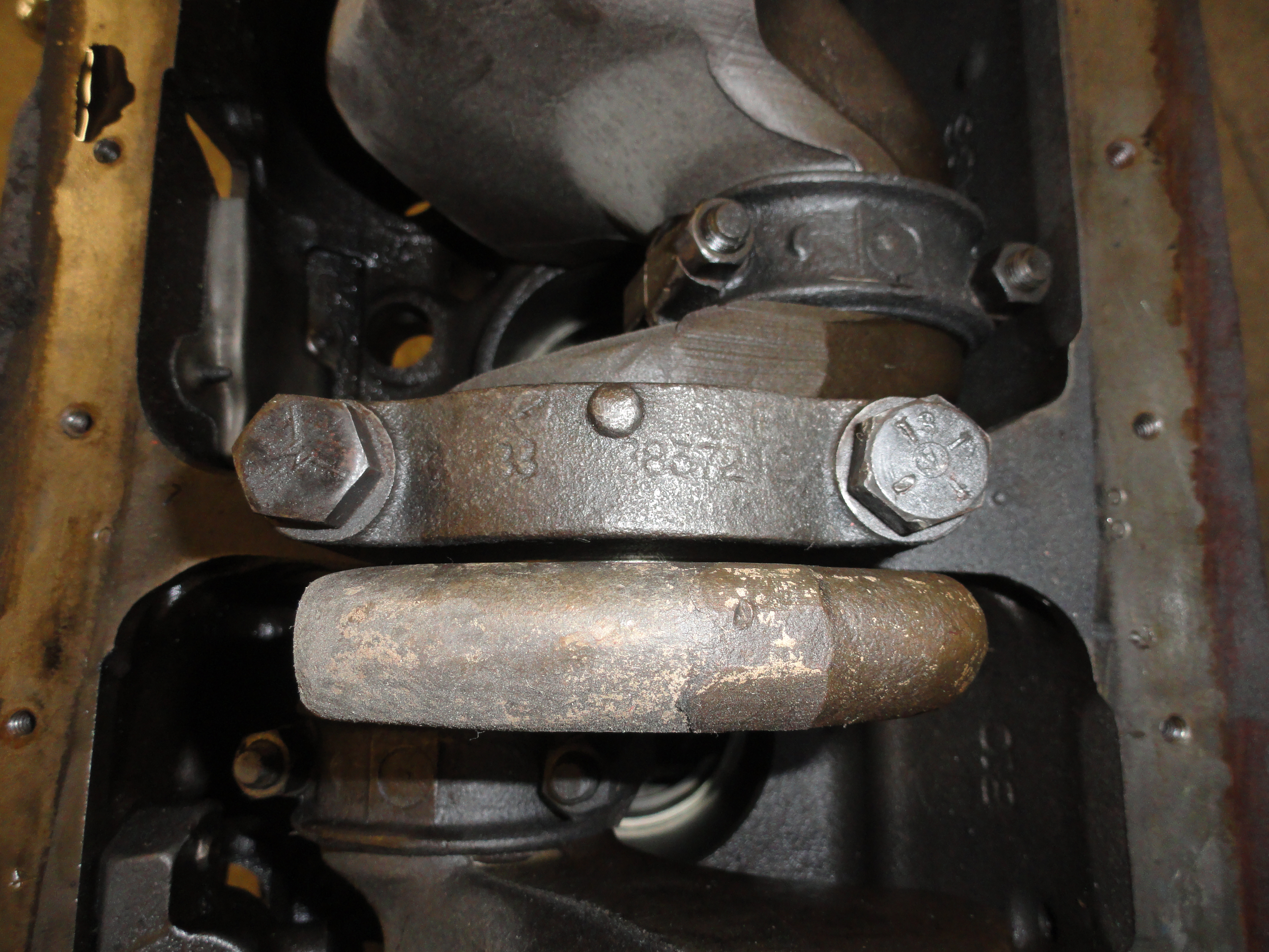
Our engine is starting to look a little bare. Everything is now out of the block except a small tin shield, the pistons, rods, and the Crankshaft. So, this is a very important stage to do right. I am very happy the previous owner decided to leave the guts in the block. This is a step that needs careful attention to detail. Here is why... Each piston rod belongs in the cylinder it was put in, in the first place. It is not a good idea to put them anywhere else. But there's more... each piston rod and cap that holds it on the crankshaft must be oriented the same direction as it was originally.
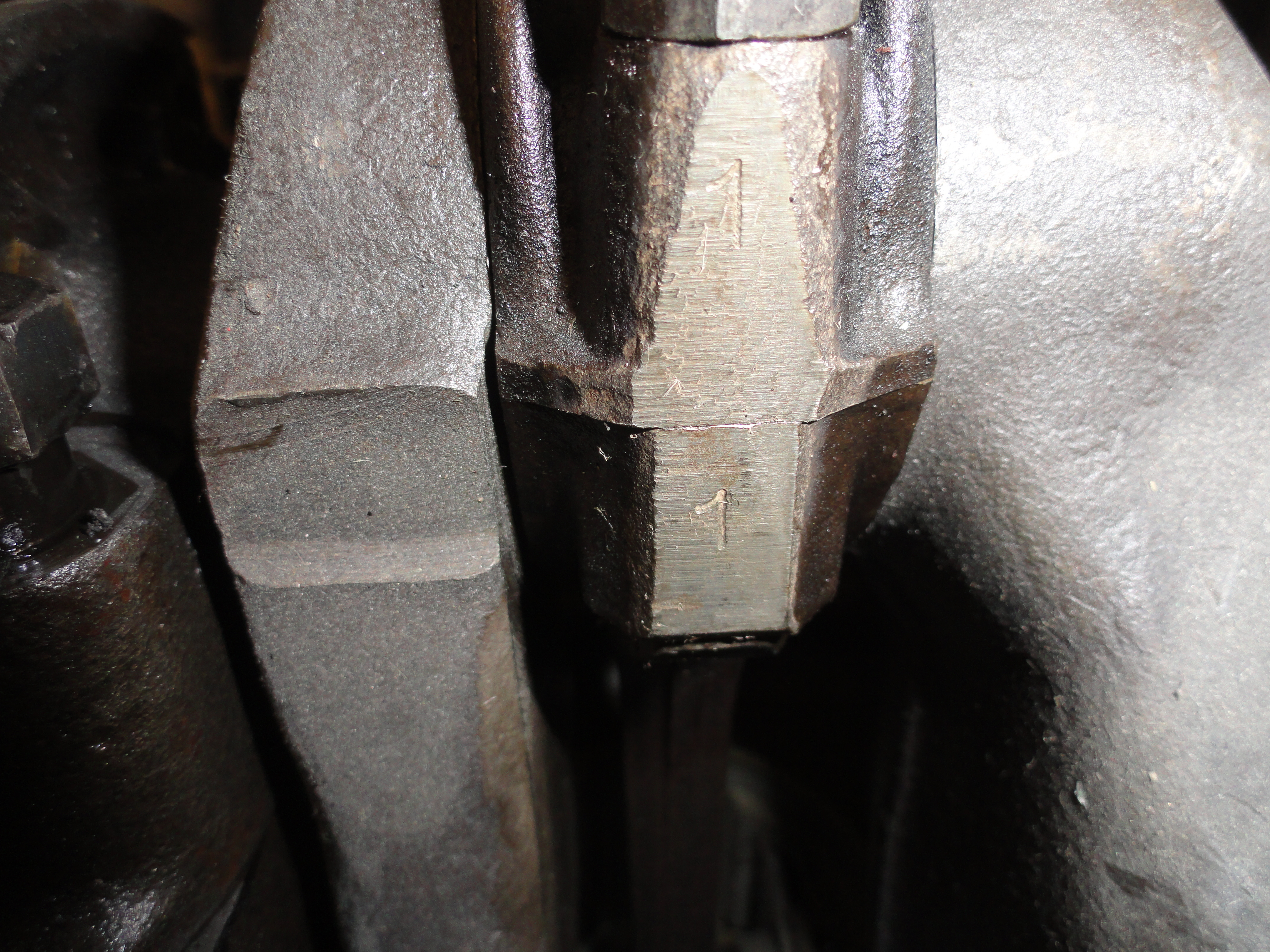

So our first order of business is to clean really good around the sides of the piston rod/cap area so that we can see what markings
are already there. We want to mark the rod and cap connection so that we know exactly how they go back together later. You can't
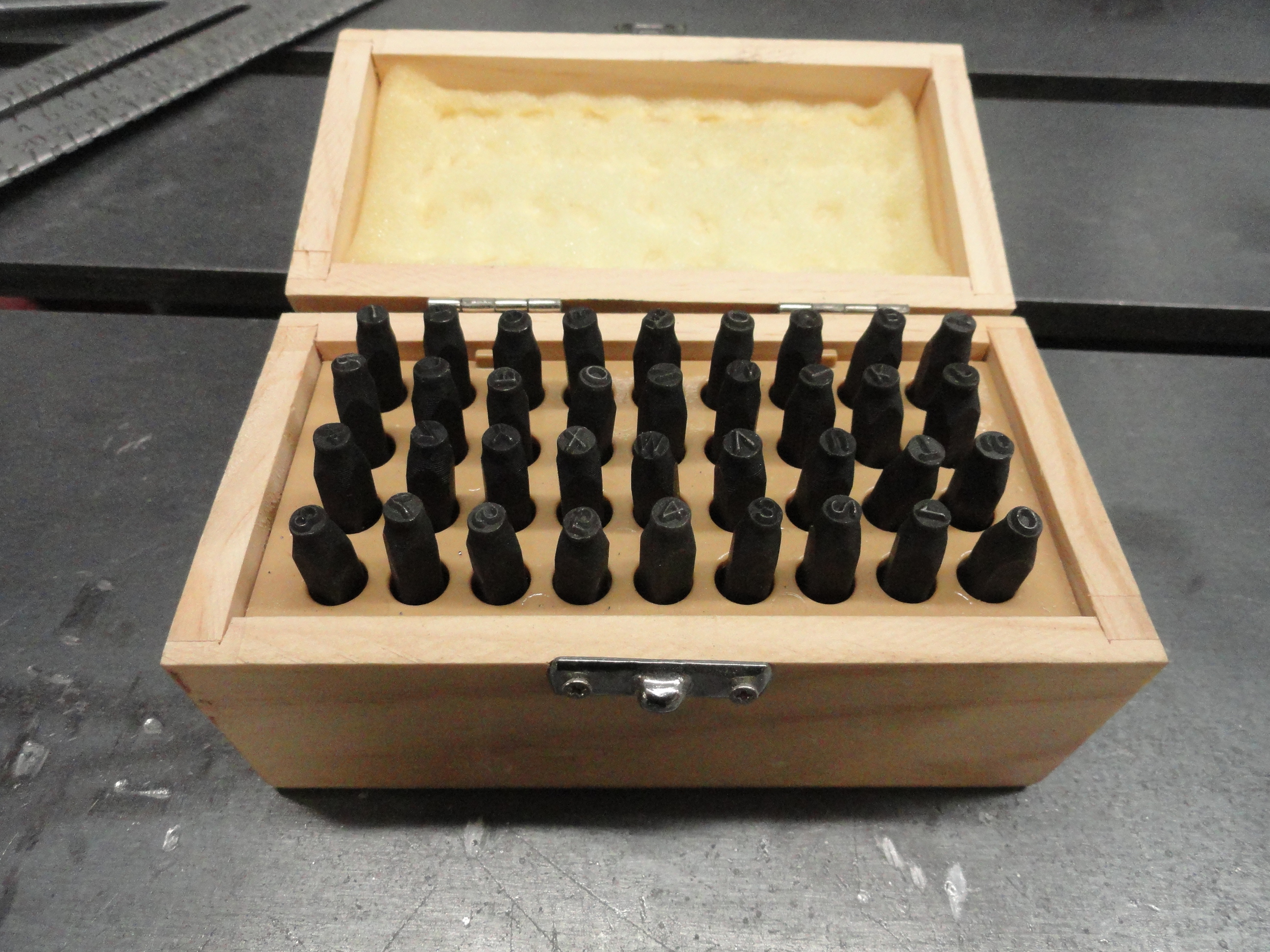
just use a sharpie for this since the engine shop will clean and inspect them. This is where it is nice to have a nice number
punching kit for stamping steel. They are relatively cheap and handy to have around the shop. Let's take a look at what is already
done for us. Sometimes they are stamped already, but not always. Upon close inspection it turns out this engine is marked every way
we need it to be. This is a critical step and can't be omitted if you expect to have a really top-notch build.
This means:
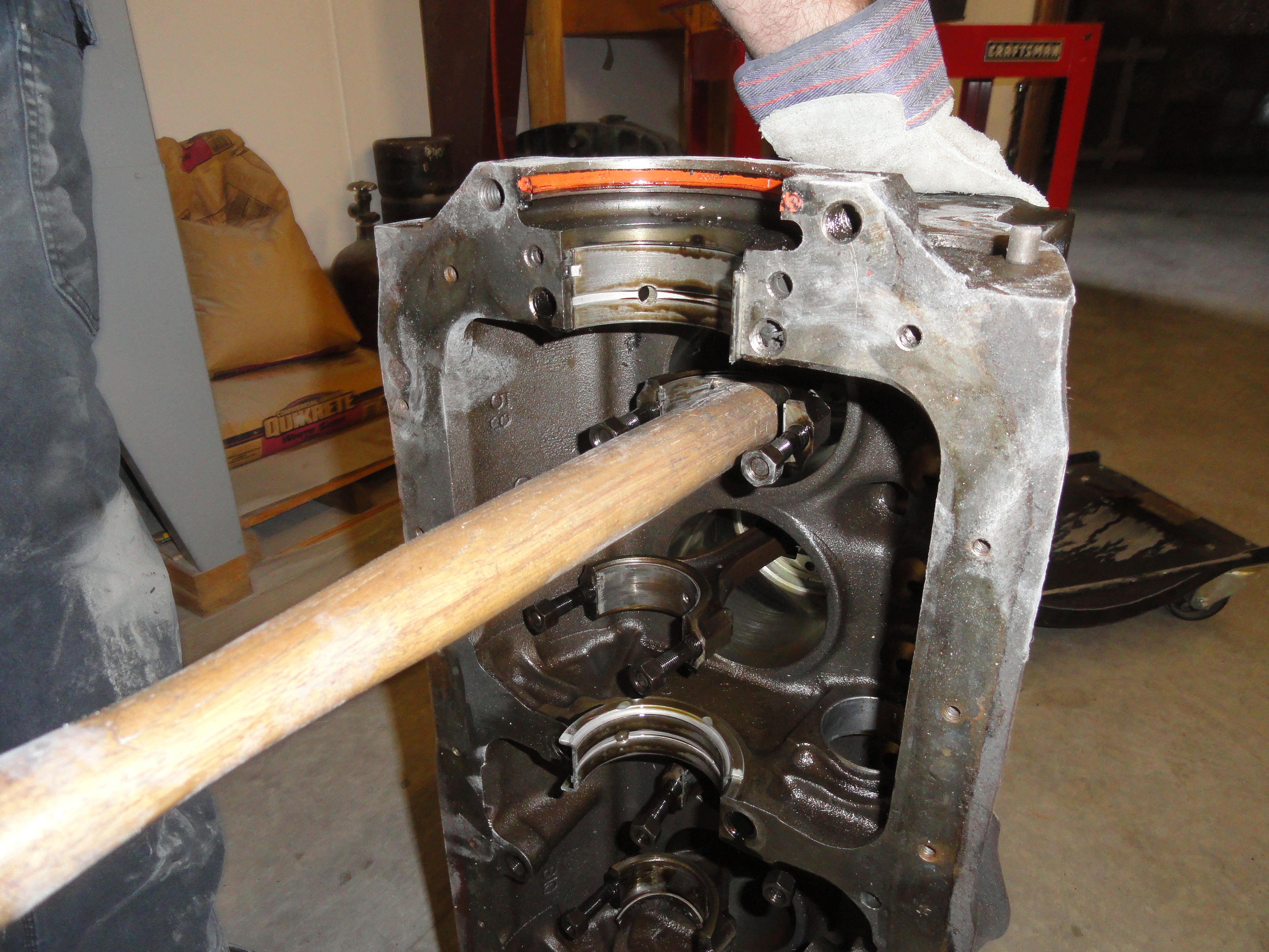
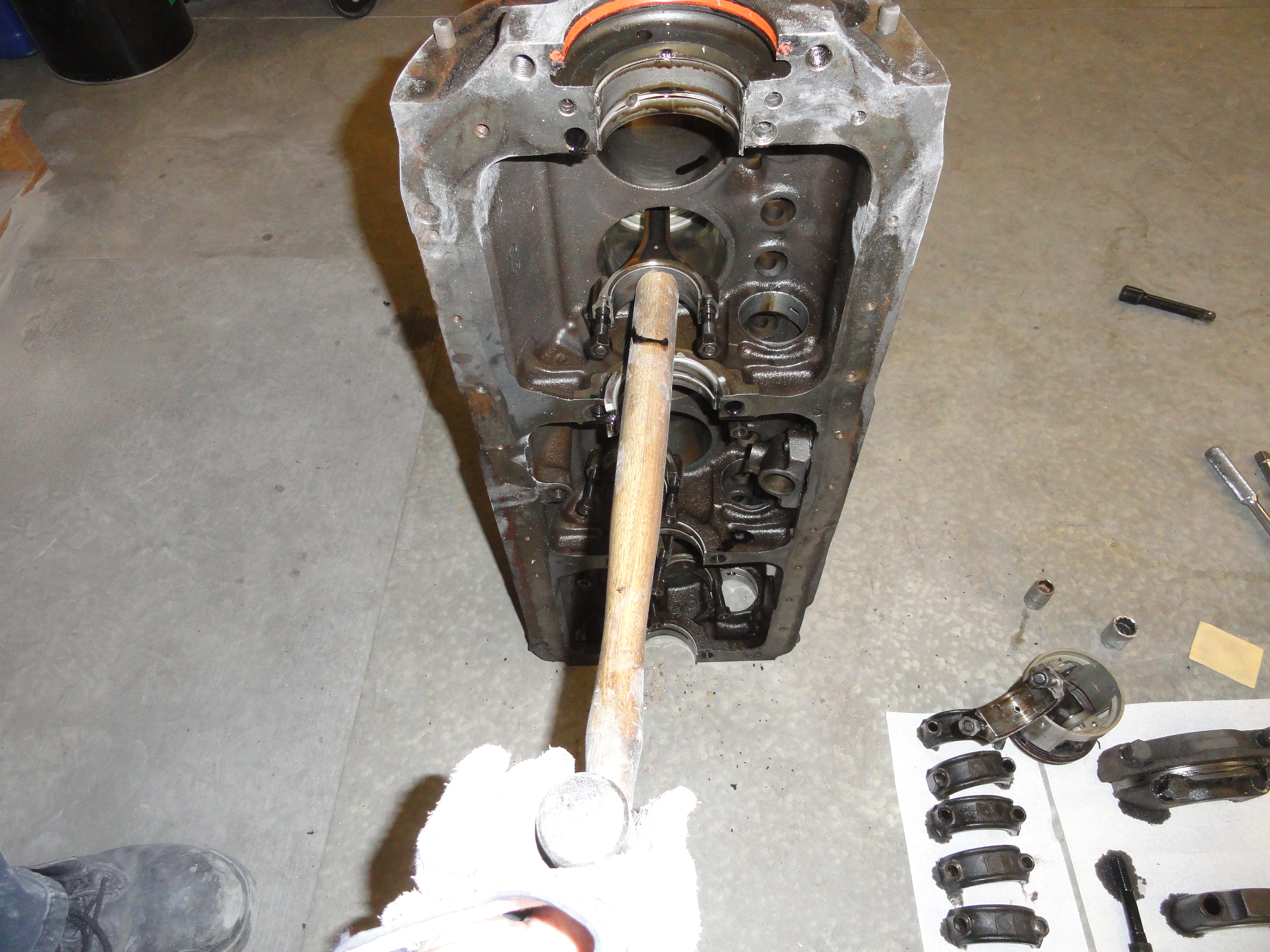
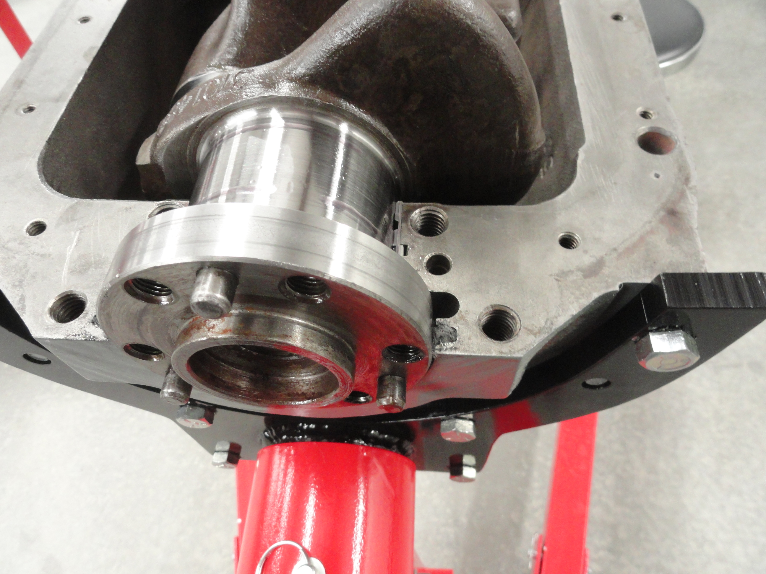
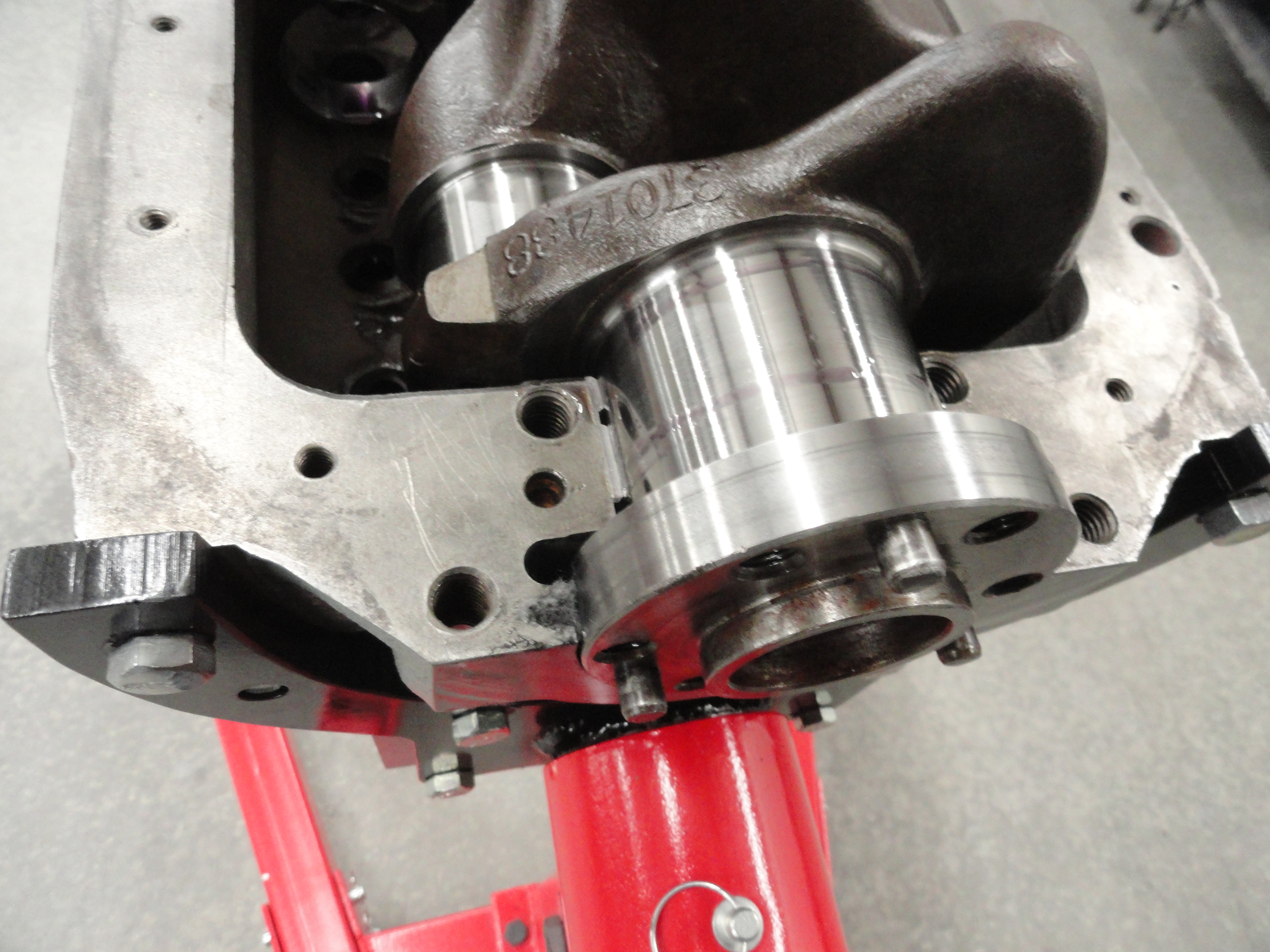
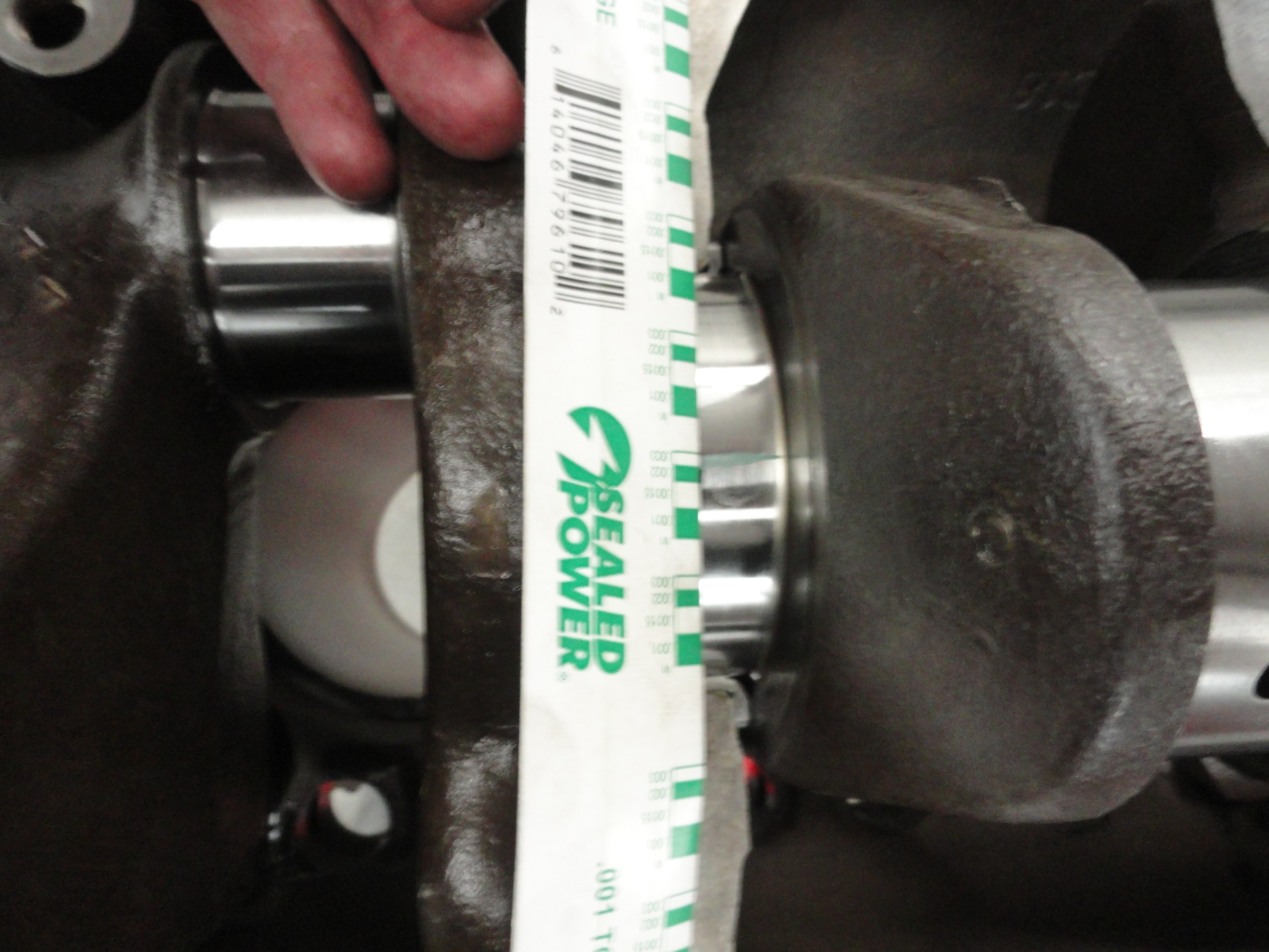
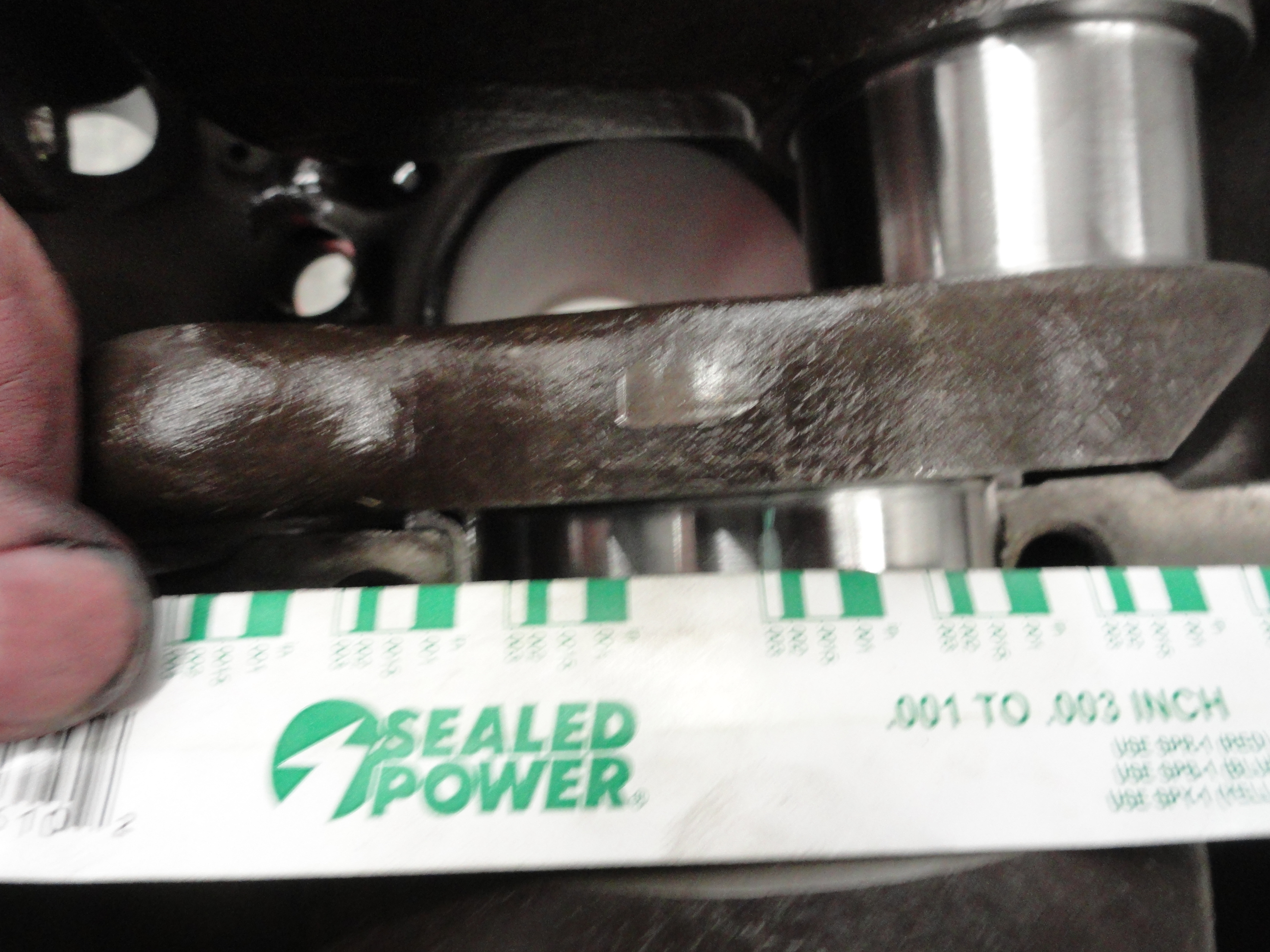
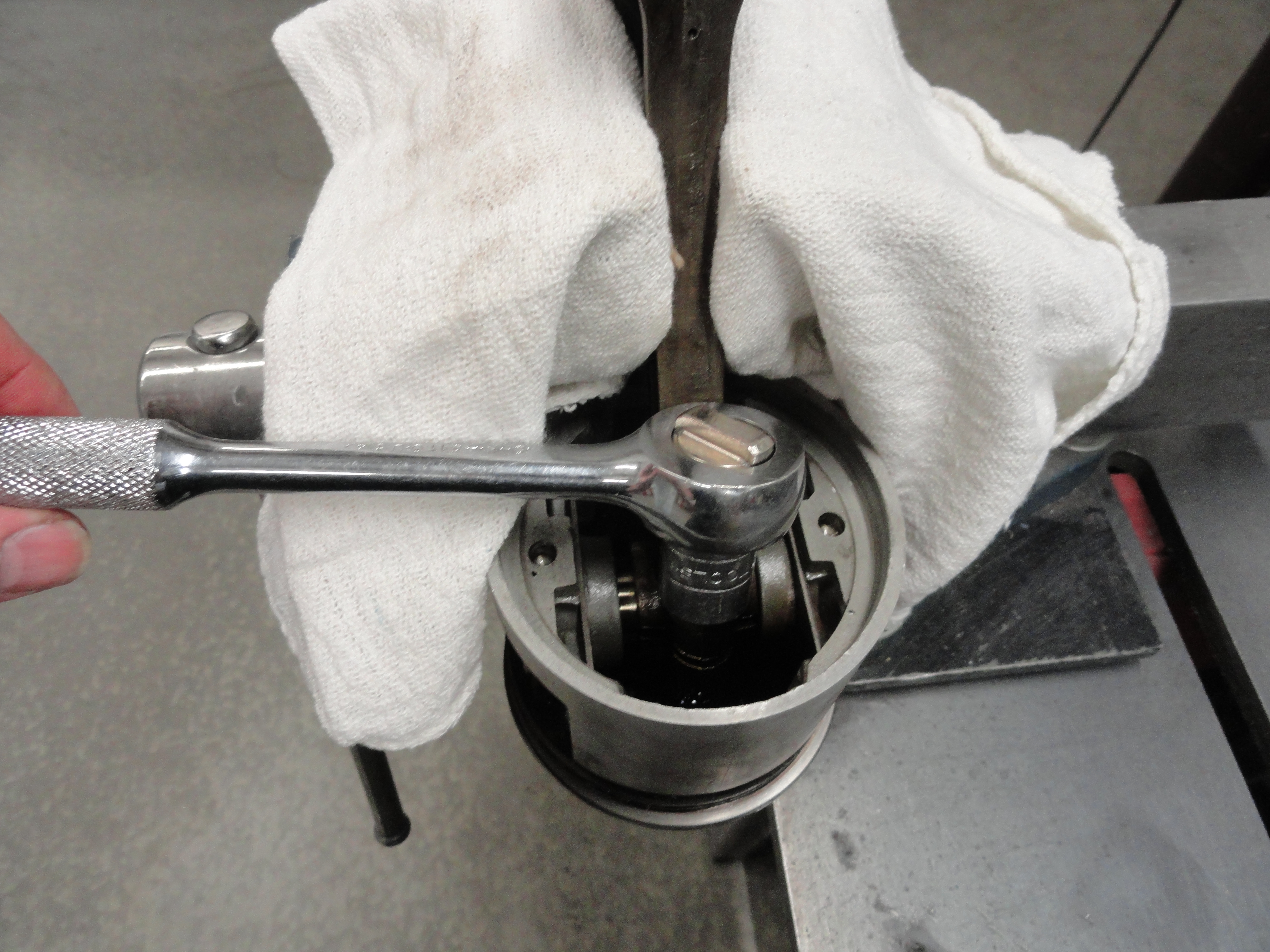
To remove the crankshaft, I use a 1/2" drive breakover bar with 3/4" socket because these bolts are torqued down very well. Remove the bolts on each cap but leave the bolts with the cap they came out of. Before you move on to the next cap, check to see if any shims are between the block and the cap. If there are, count them, write down the exact location they were in, and keep them with the cap in the location they were in. You will want to tell your engine shop this when you take the engine to them. This particular engine didn't have any shims. None is good. Once the caps are off, place them in the order they were in on a table somewhere to prepare for cleaning. Now we have a crankshaft with the pistons still attached. Let's remove the piston rod caps. I use a 1/2" drive, 9/16" socket on my ratchet and just removed each one, one rod at a time. The way I break the rods loose from the caps is, I leave the nuts on the rod, but unscrewed all the way to the end, then wrap the two nuts/rods with a short piece of 2x4 wood. Never use metal on metal. Once the cap is loose, you can just pull it off. Chances are the bearings will fall out. Other than inspecting them just to see how they wear, they are trash. Look carefully at the orientation of them though. You will see there is only one way of putting them on correctly.

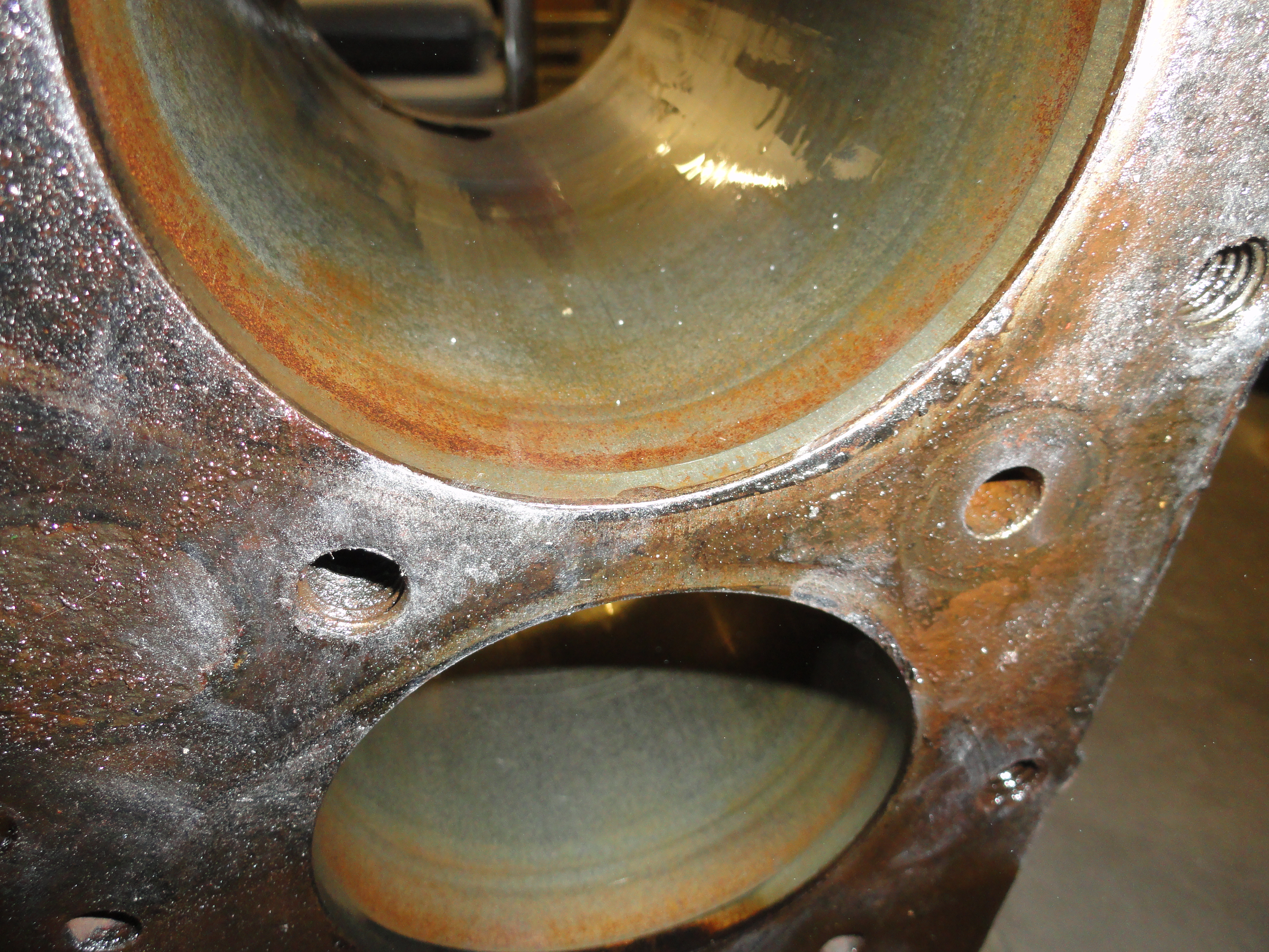
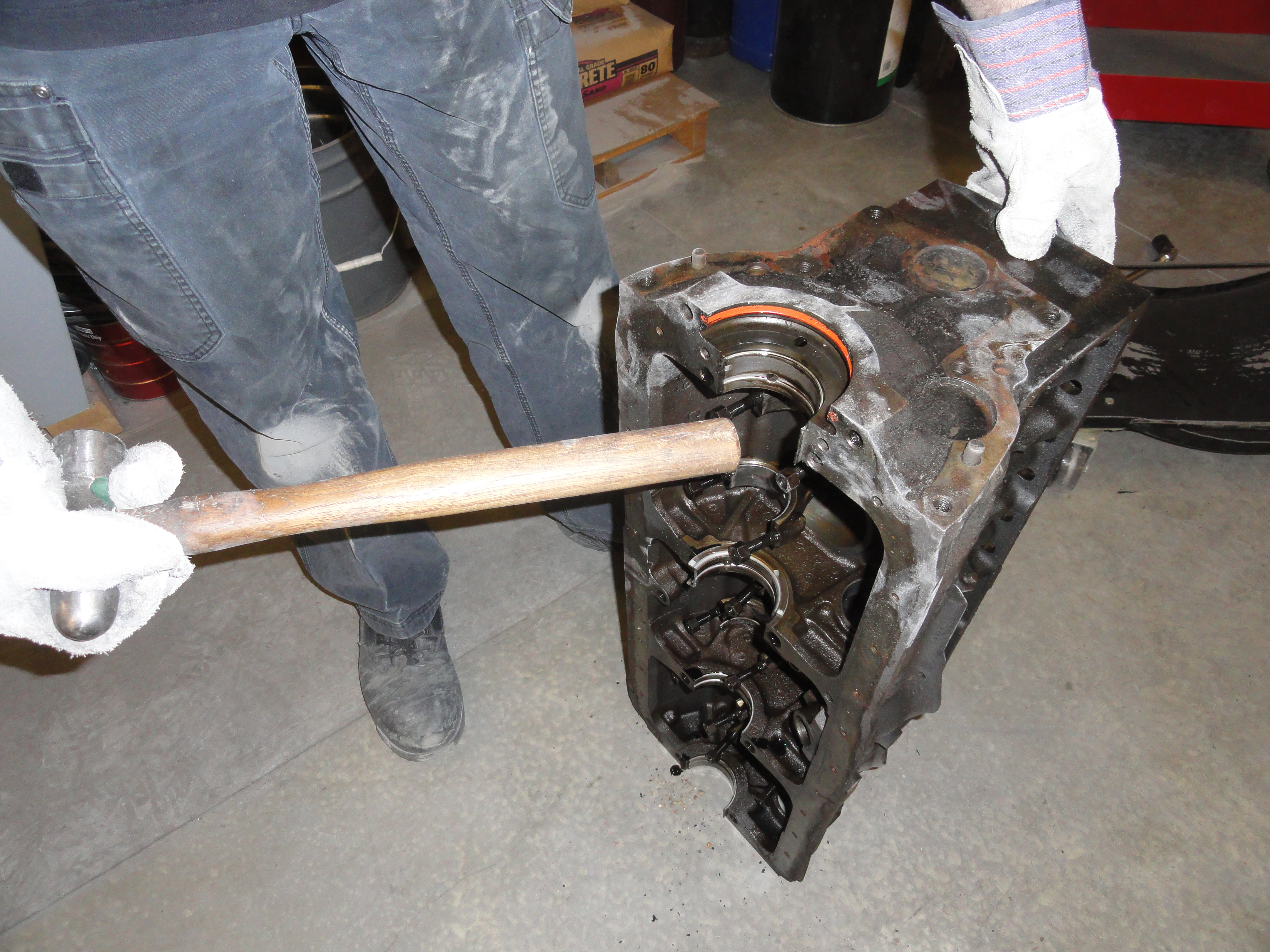
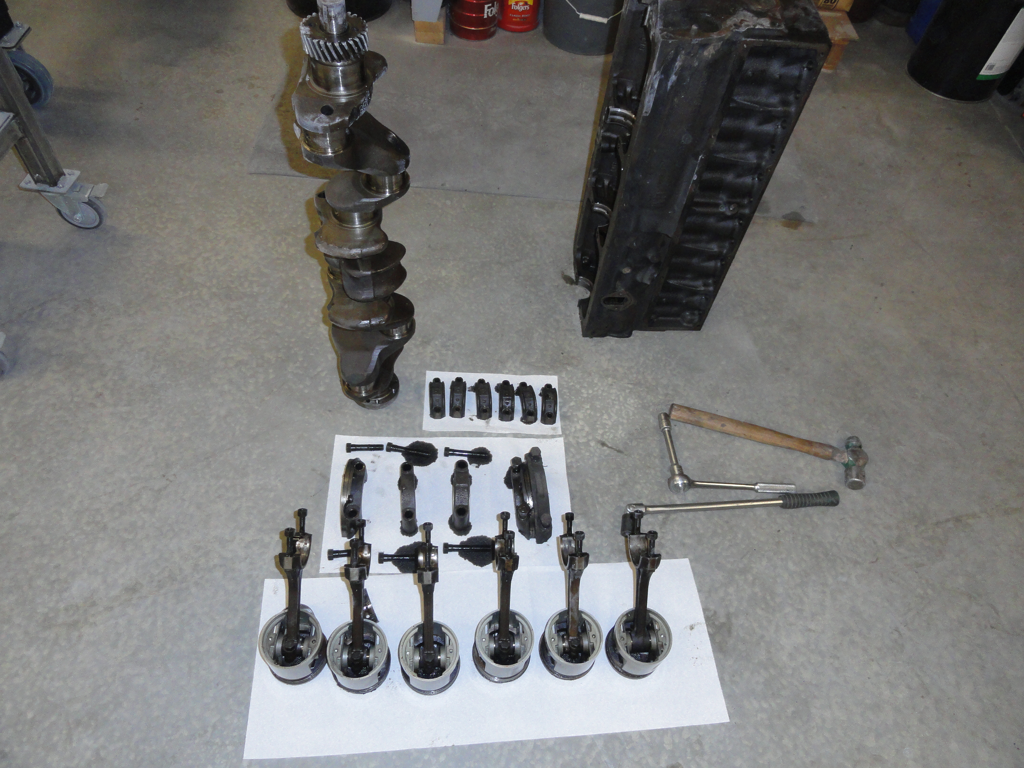
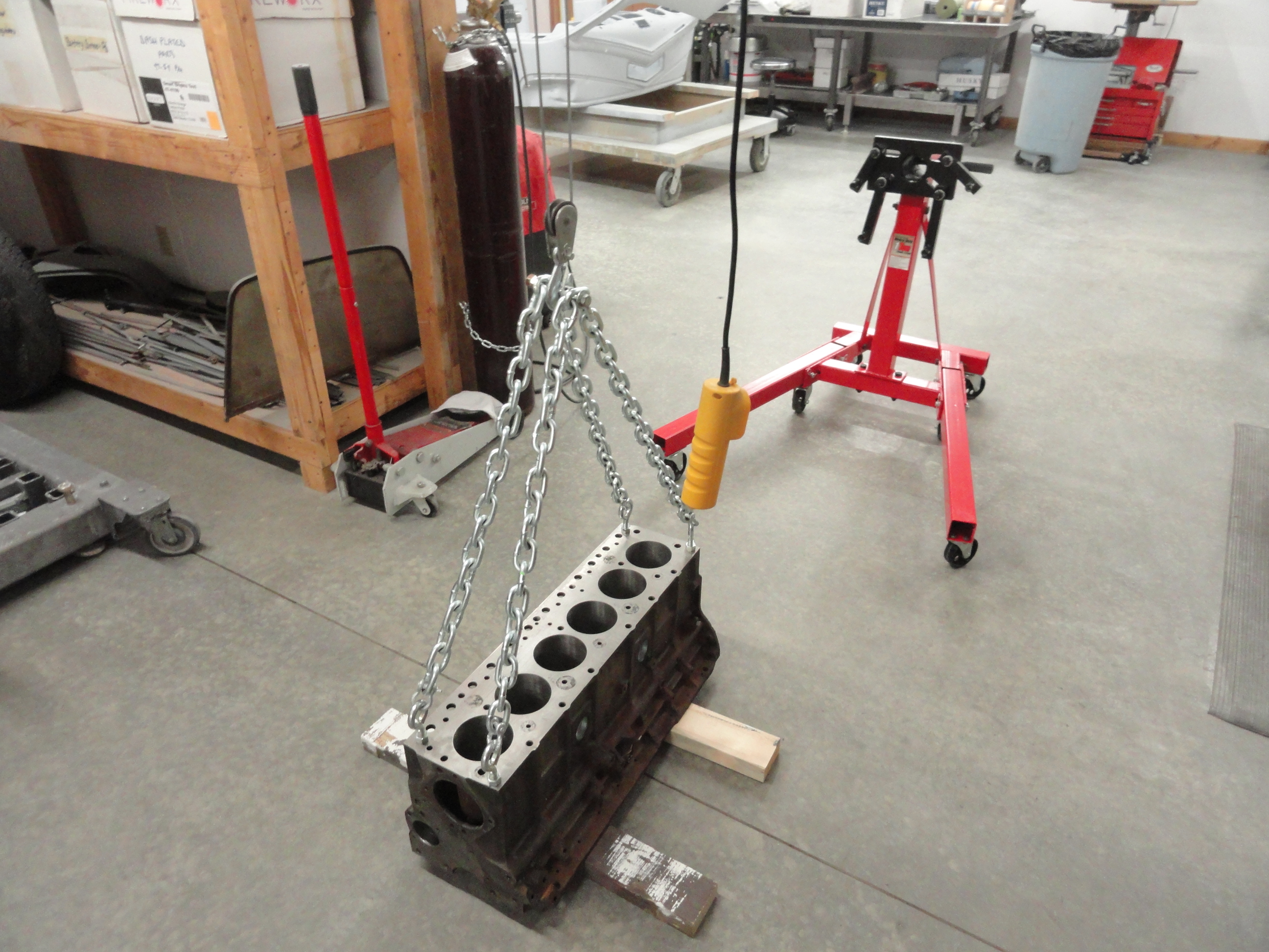
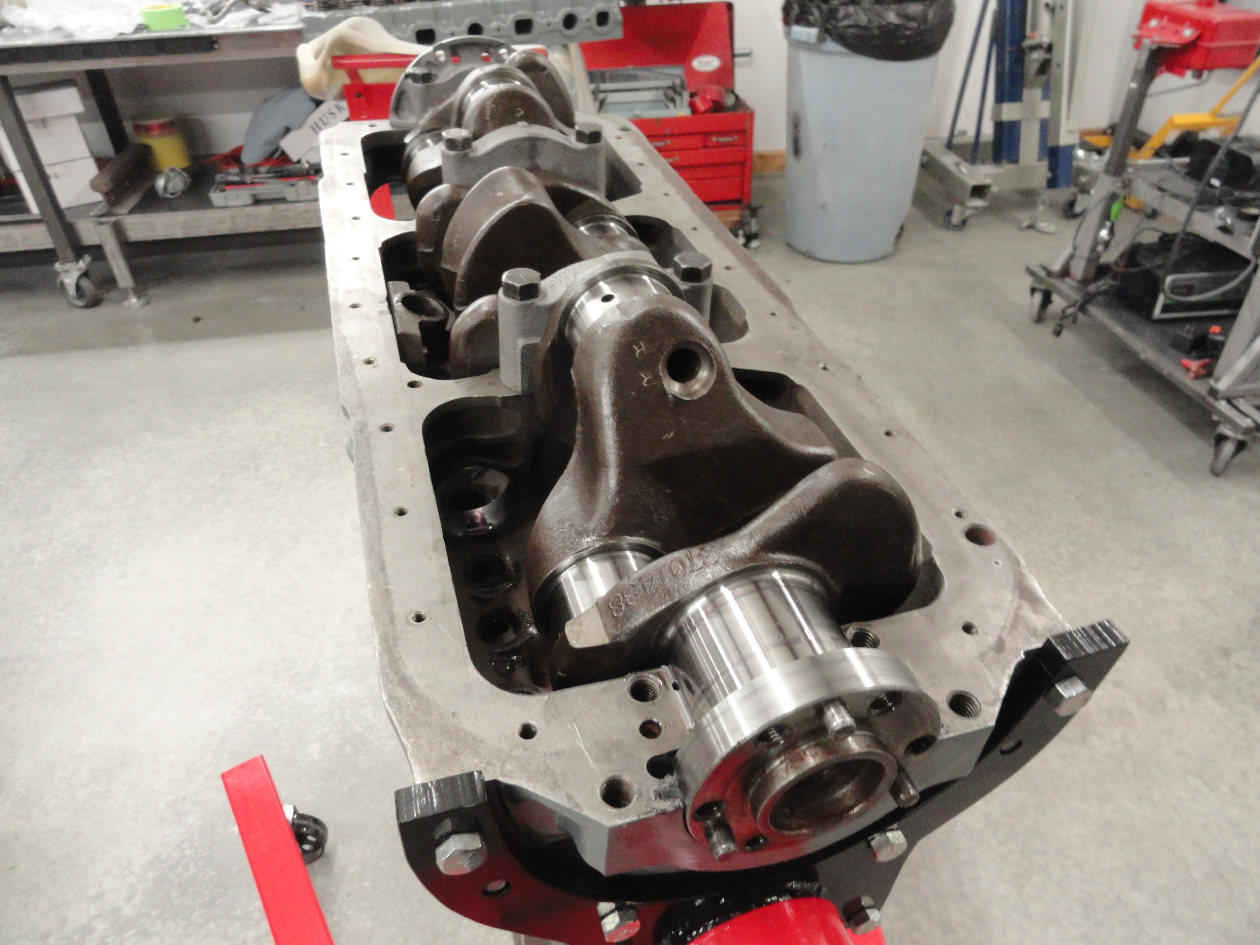
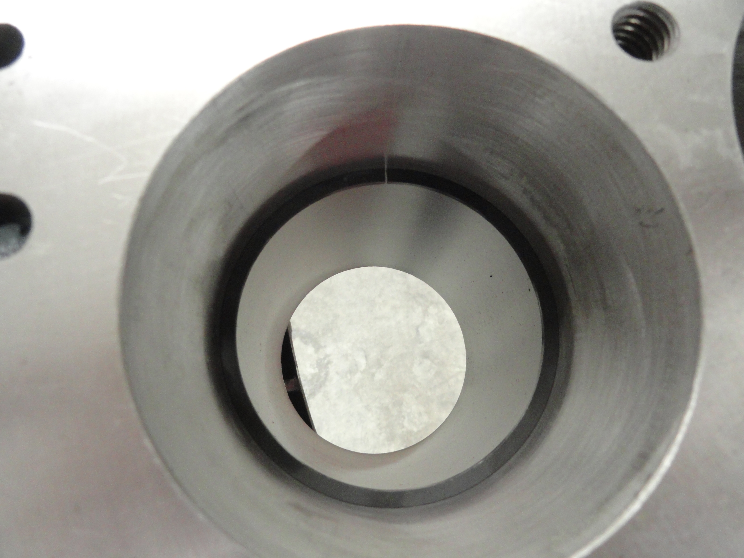
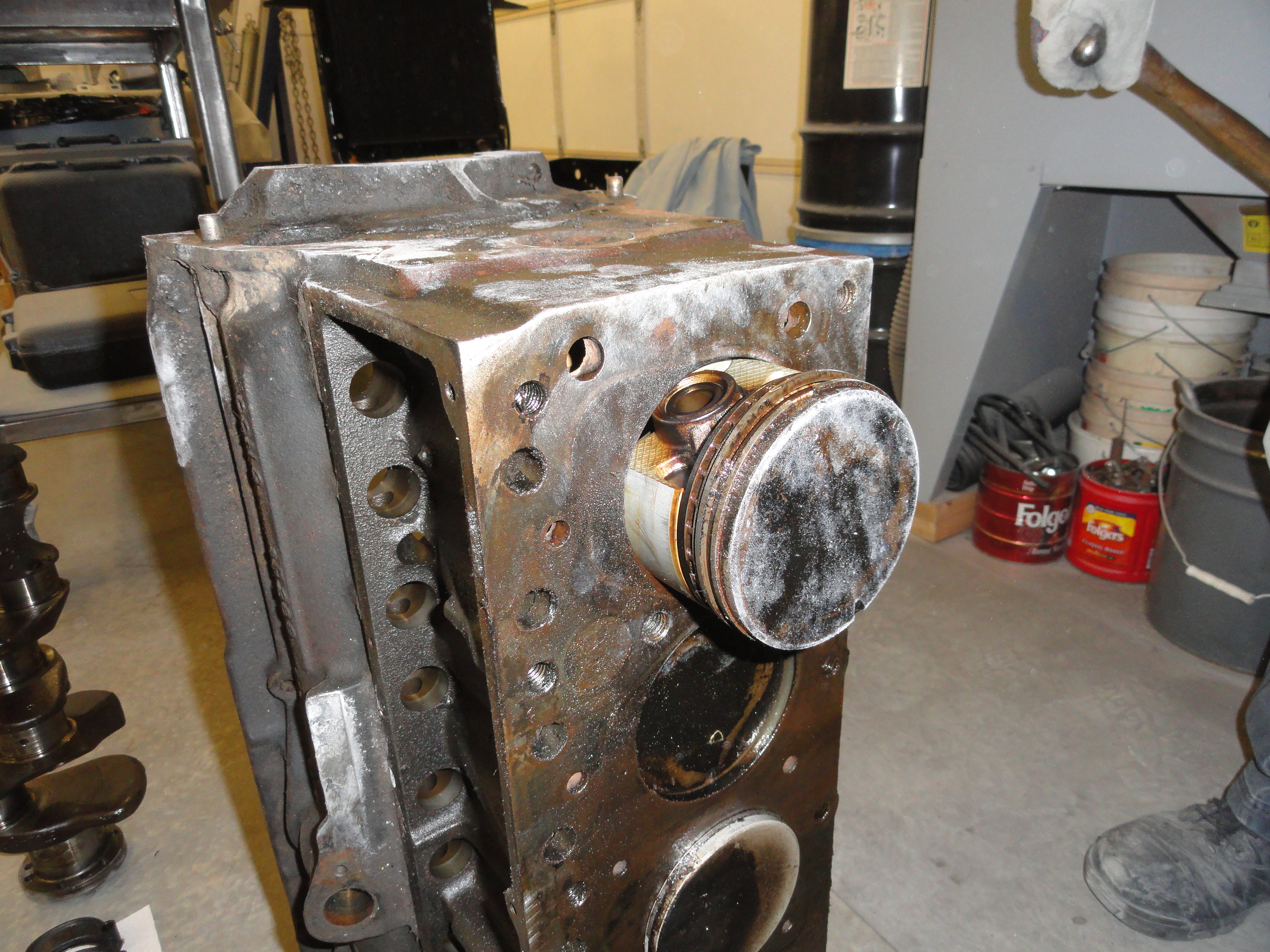
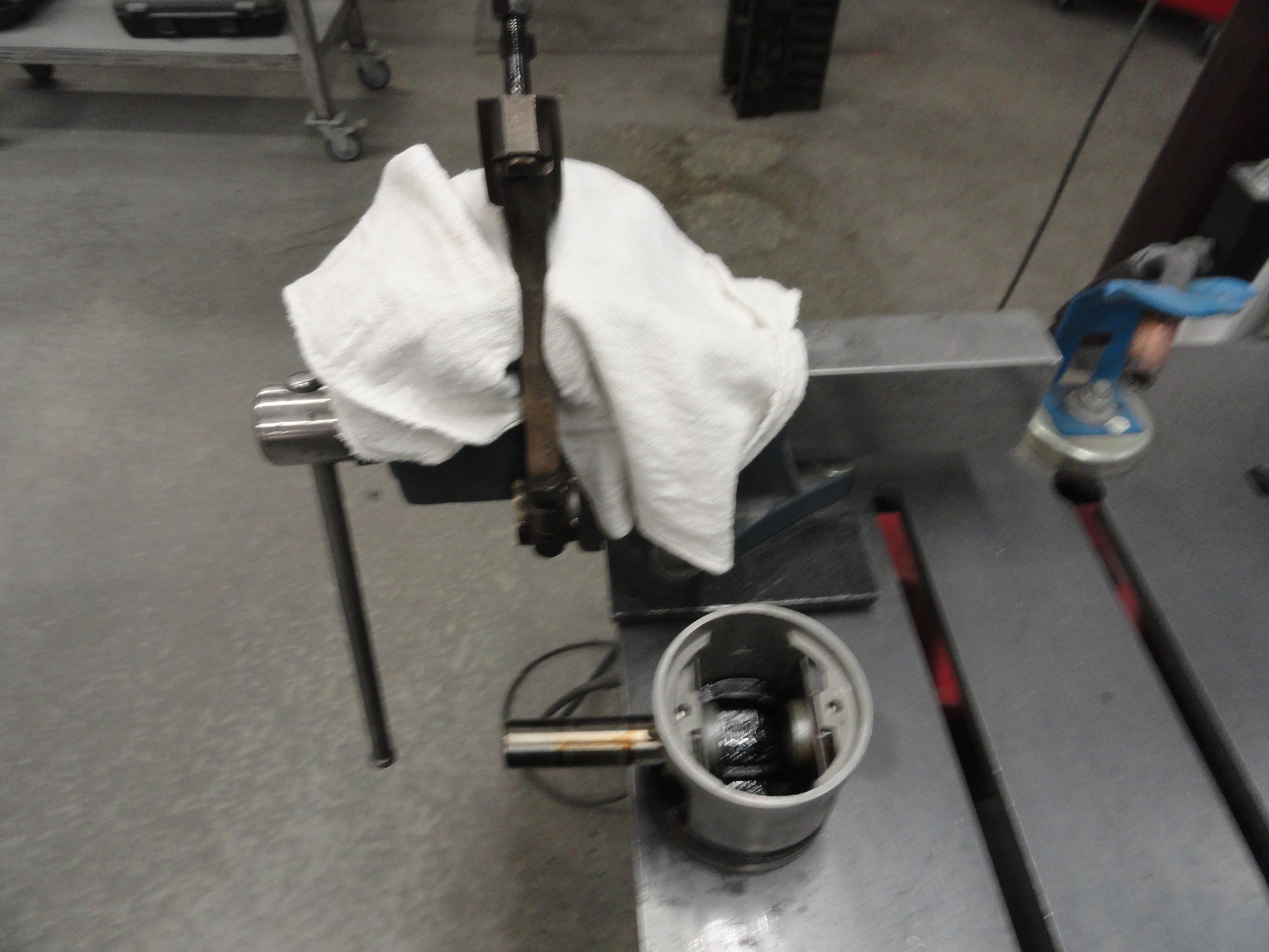
Once each cap is removed from the crankshaft, remove the nuts and let the piston drop away. Once all of them are done this way, your crankshaft is now free. This is a VERY heavy crankshaft and it's very important you don't drop it. Remove the crankshaft and stand it up in a corner somewhere. Make sure it's in a place where nobody will touch it. It's not good to lay a crankshaft down flat any longer than you have to. With the crankshaft out, you now have 6 pistons/rods to contend with. To do this next step, you need to be able to get to the top and bottom of the engine block. As nice as it would be to just push the pistons out the top of the block, we have to use a new tool first. If you run your fingers inside the cylinder, chances are very good that there will be a ridge at the top of the cylinder. This is because over time, the pistons push crud as far up as the top rings can push. This leaves a ridge about 3/16" wide or so. It can be so bad you simply can't get the pistons out. We do not want to ruin the cylinder walls by forcing anything, so let's get out our shiny new Ridge Reamer.
The way this contraption works is, it adjusts to the size of your cylinder, then a single blade with a pad on one end cuts the ridge out of the cylinder. It only goes in the cylinder one way. Set it in place and turn the center bolt until the reamer is semi-tight in the cylinder. Using OIL very liberally, switch to the larger socket and turn the reamer in the cylinder. Give it a few complete rotations, then tighten just a little (since it should need it) and do it again. After a few more times doing this, your ridge should be removed. Do not Gorilla anything, just smooth and easy movement until the job is finished. It's finished when there is no ridge left. When you have done that, the piston will slide right out. In the case of this particular engine, there was no ridge at all. This is the first time I have seen this. They almost always need the ridge removed. With the cylinder oiled, you can now just tap the pistons/rods out with your hammer handle (if it's wood), or just about anything being sure to guide the rod out without it scratching the cylinder walls.

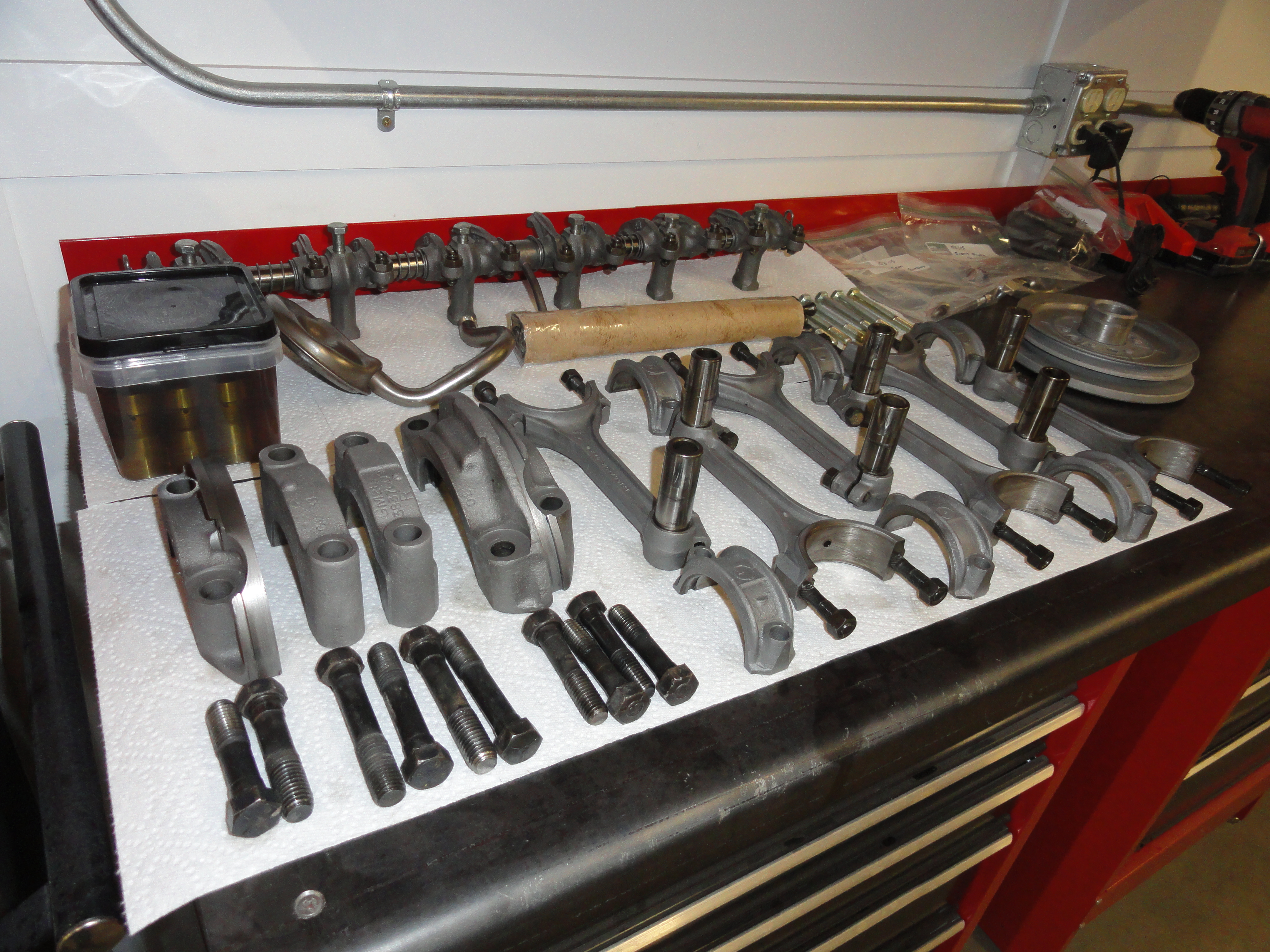
We are not done preparing the block for the machine shop yet, but we are well on our way. Now we need to clean the rods, caps, everything you just removed. Remember, no harsh treatment of anything that could affect measurements. I will tape those areas before blasting, and if you do not blast, just clean everything off in your small parts washer, put all of the hardware in labeled ZipLock bags, and prepare to take them with you to your engine shop.
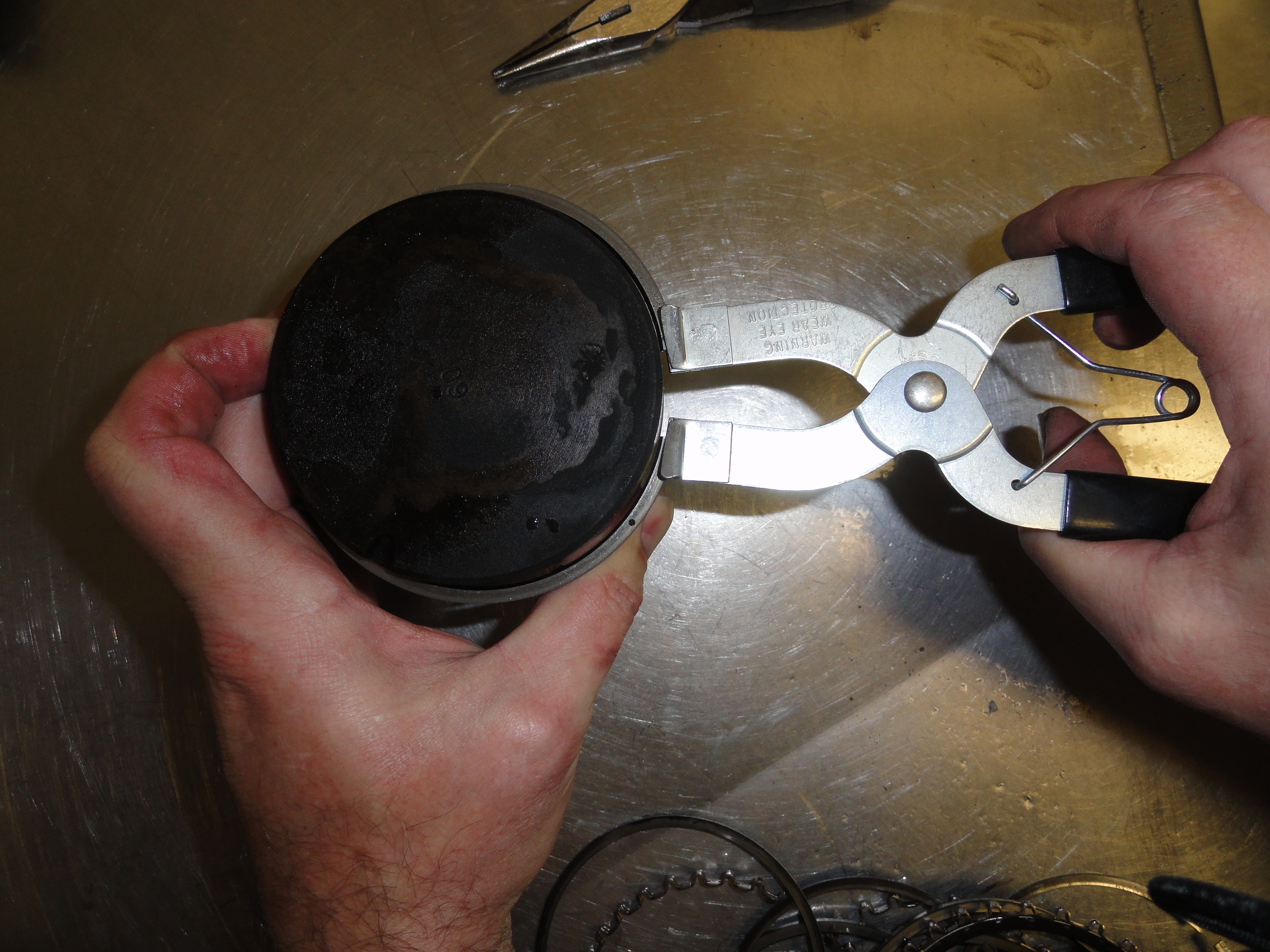
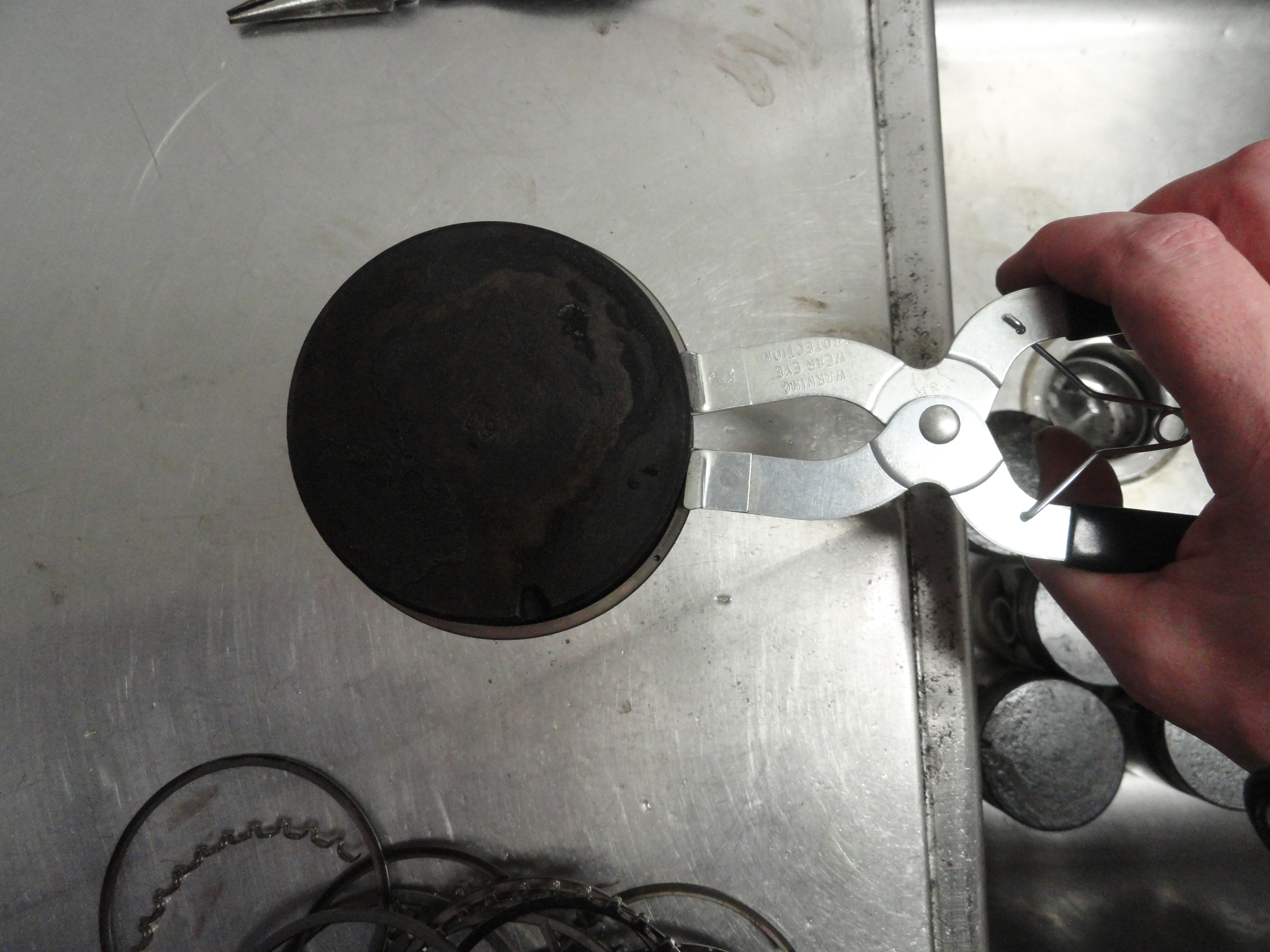
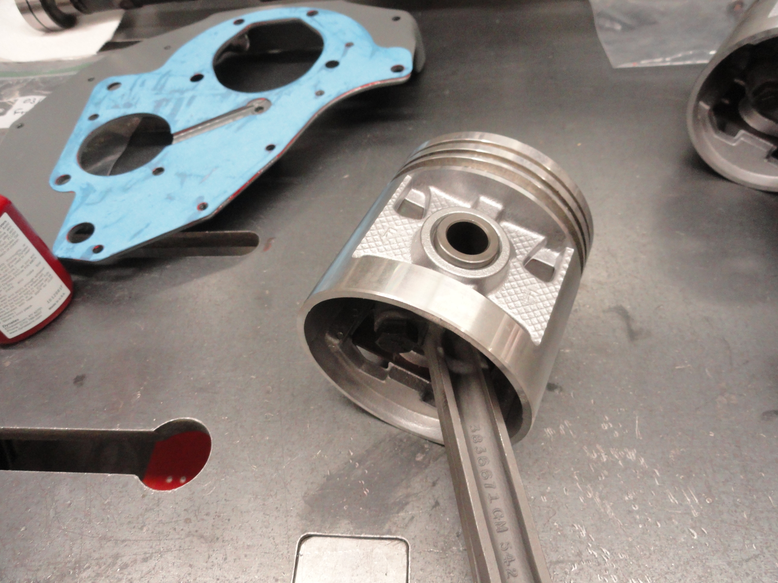
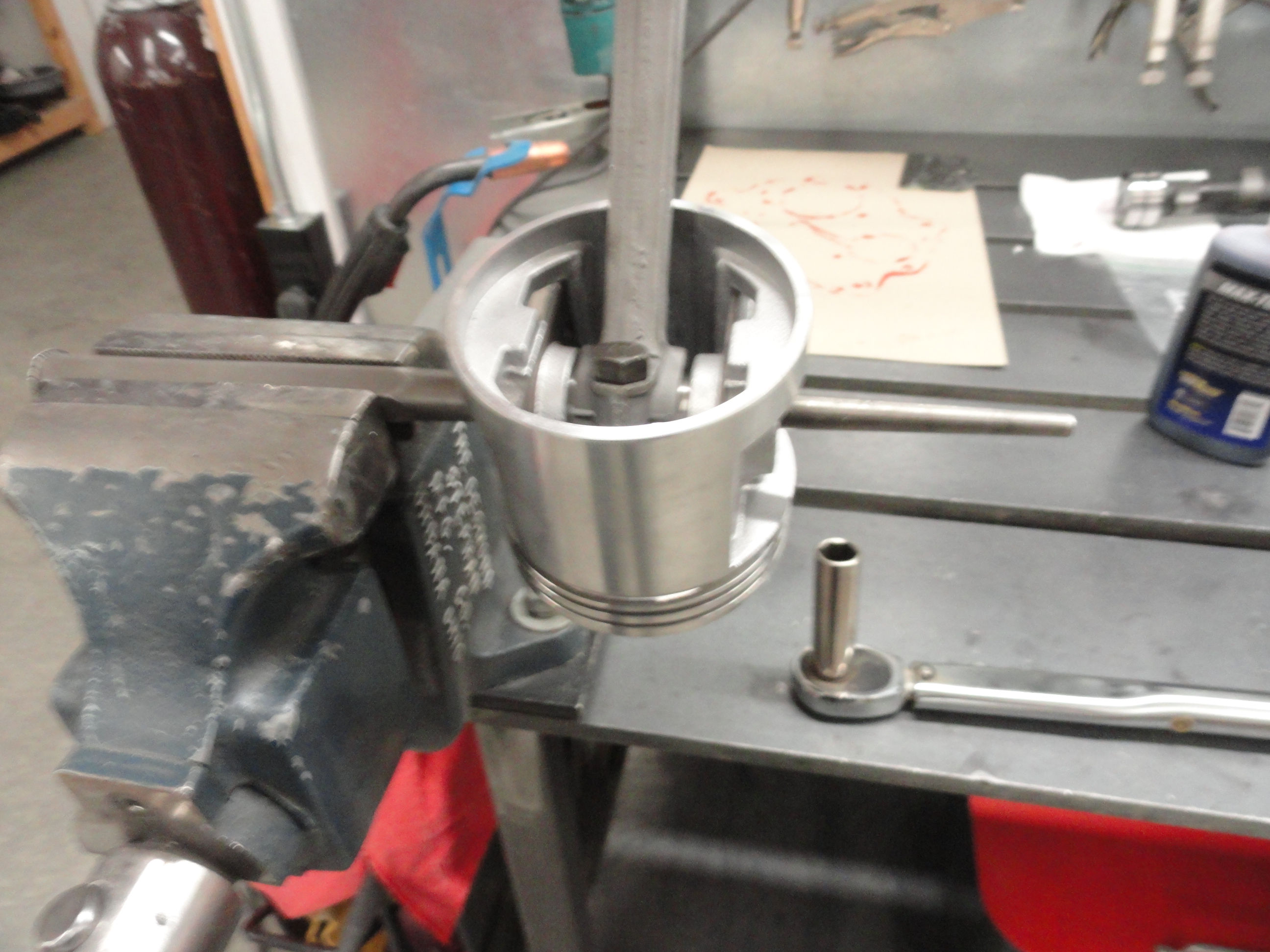
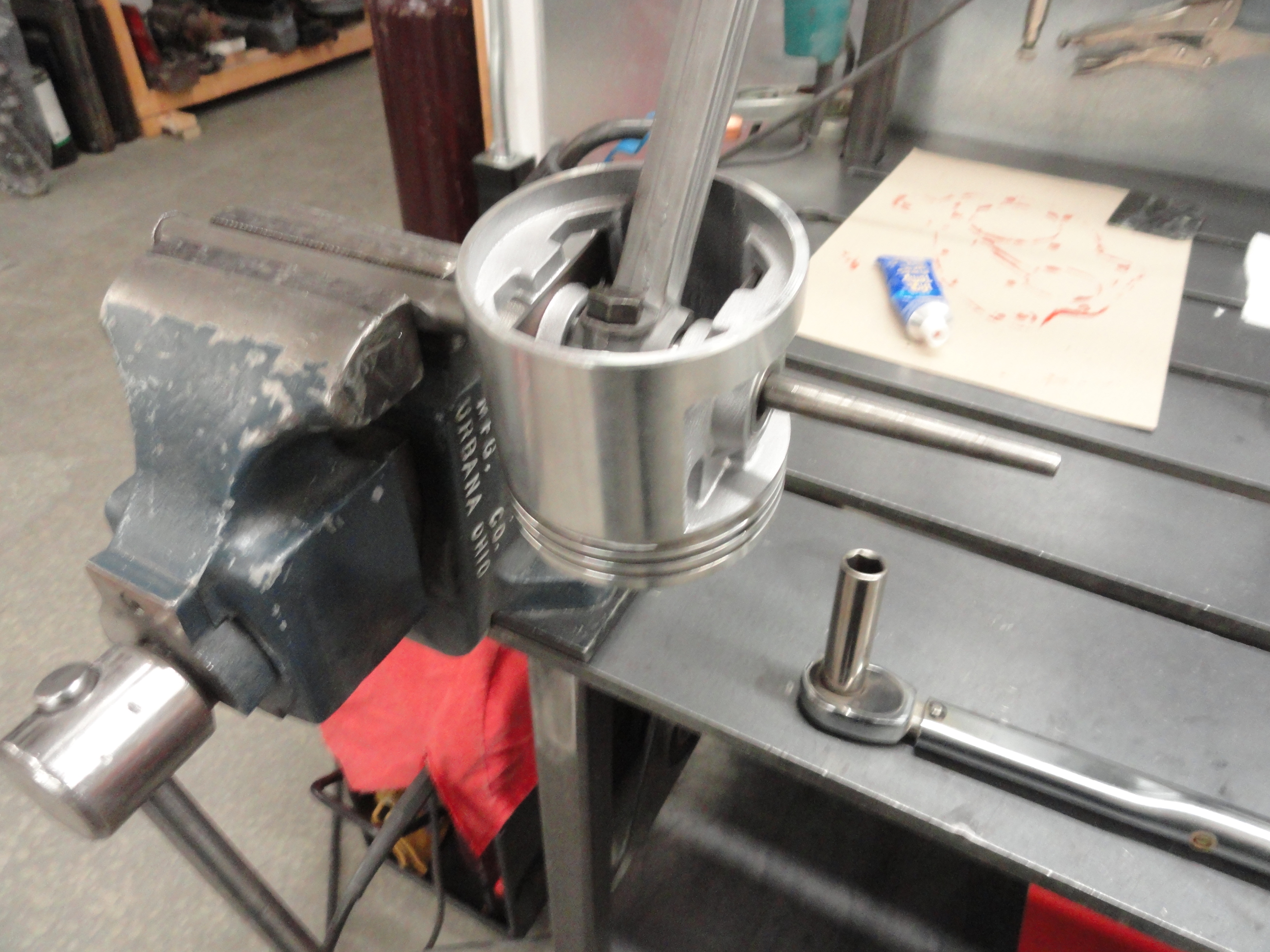
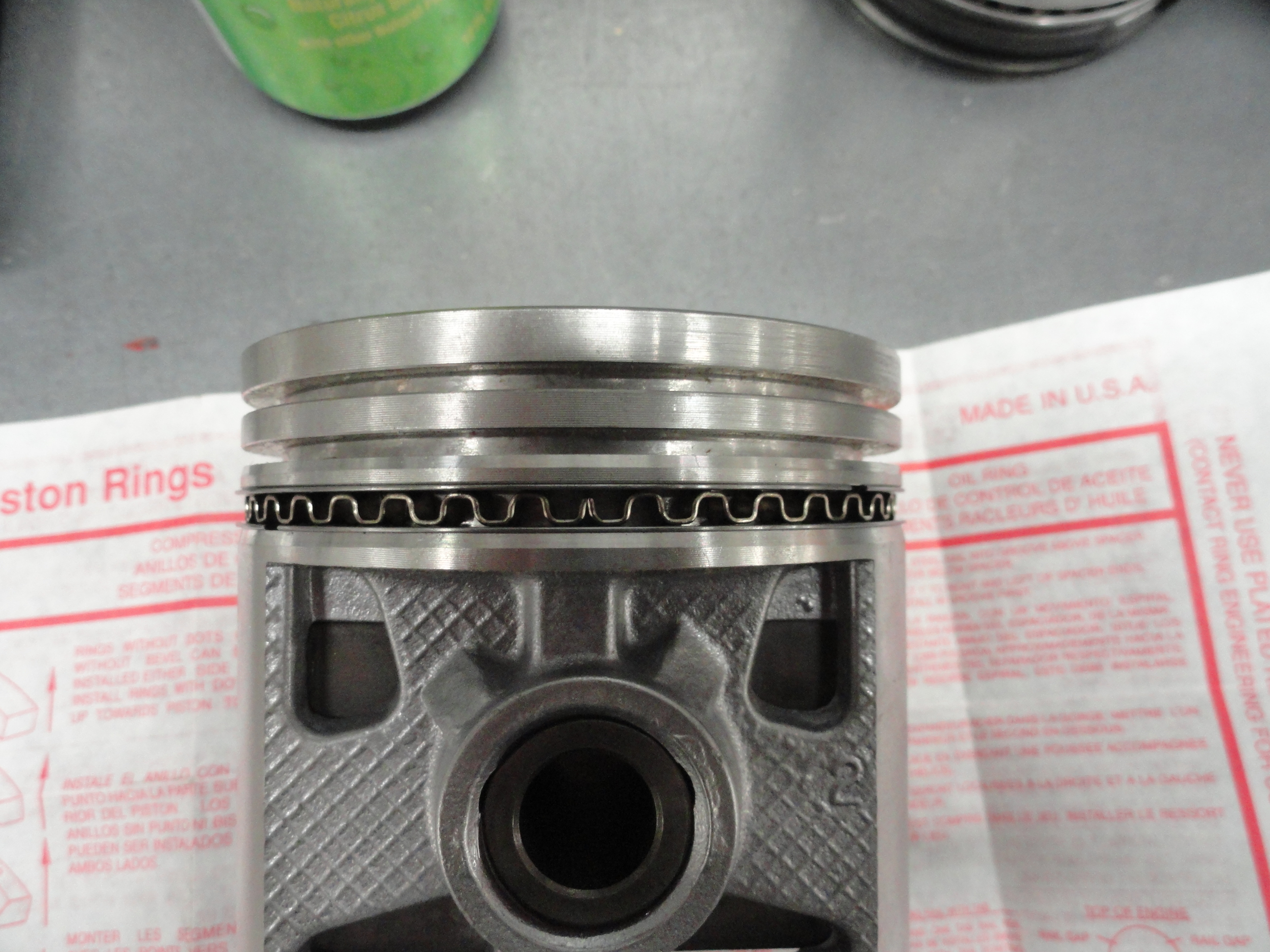
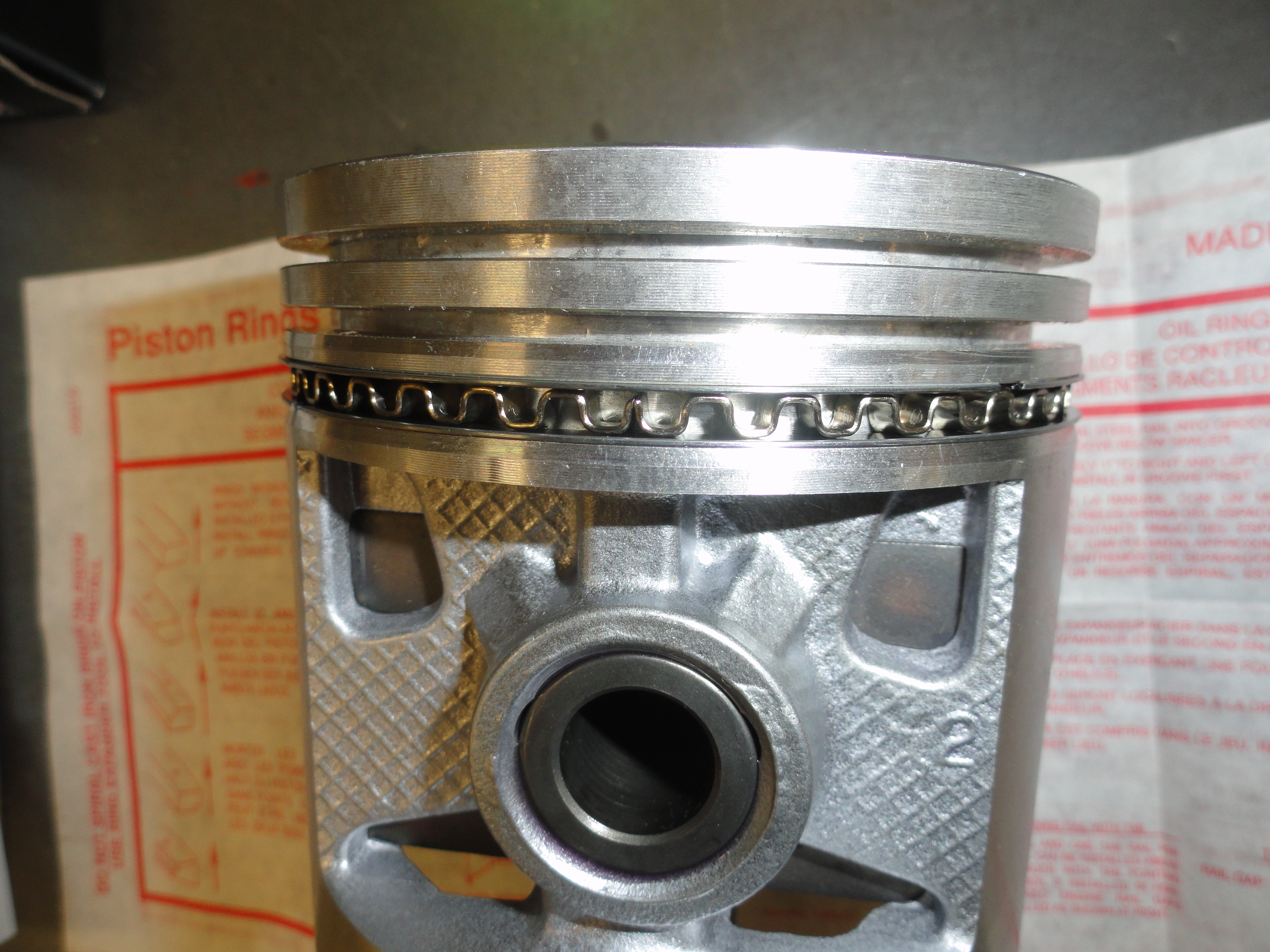
The pistons and rods come apart very easily. There is a 9/16" hex head bolt just inside the piston/piston rod connection. To loosen this bolt and nut, do NOT put the rod in a vise! You can potentially bend the rod and cause real problems. Rather, take a long punch and put it in the vise sticking out so you can put the piston via the piston rod hole over it giving you the leverage to remove the bolt. The bolts are on tight, but your 3/8" ratchet is adequate for the job. Loosen the bolt but do not remove it. By just loosening, the rod should push right out. The pistons and rings won't be re-used, but I like to remove the rings and clean up the pistons anyway. I do not like dirty stuff sitting somewhere in my shop! At this point its a matter of cleaning everything to your satisfaction. Once this round of cleaning is over, we can address preparing the engine block.
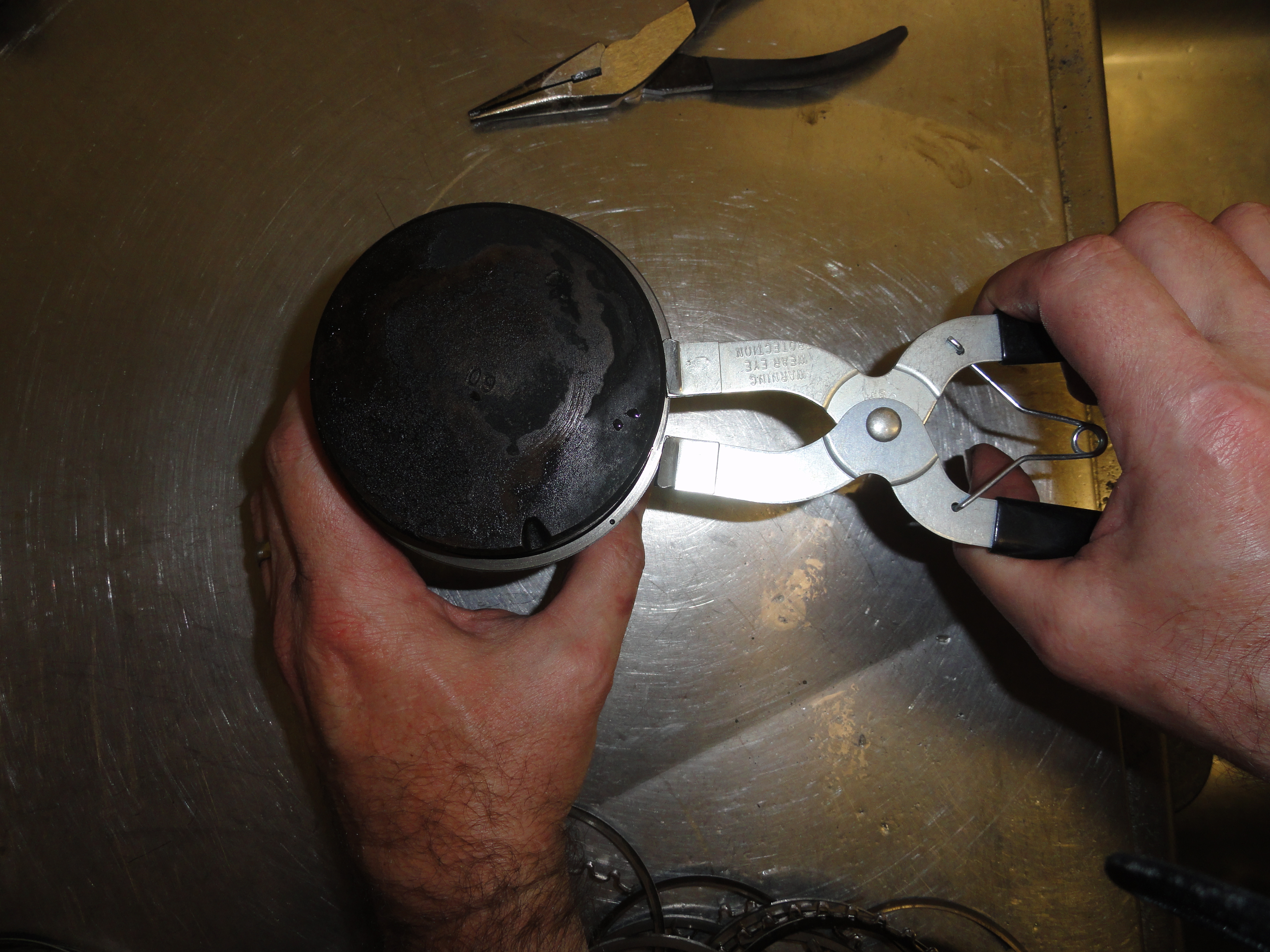

Since the pistons and rings won't be re-used, I take them apart, toss the rings and clean the pistons. There is a nice little tool that makes removing and installing piston rings pretty easy, Piston Ring Pliers. They are inexpensive and worth having in your tool arsenal. They are available just about anywhere engine tools are sold. So, other than addressing a few remaining engine block and head issues, we are just about ready to make the trip to the Motor Machine Shop. No matter what the machine shop says as far as if your block and head are healthy and worthy of the effort, most of the work you have done so far is still time well spent.
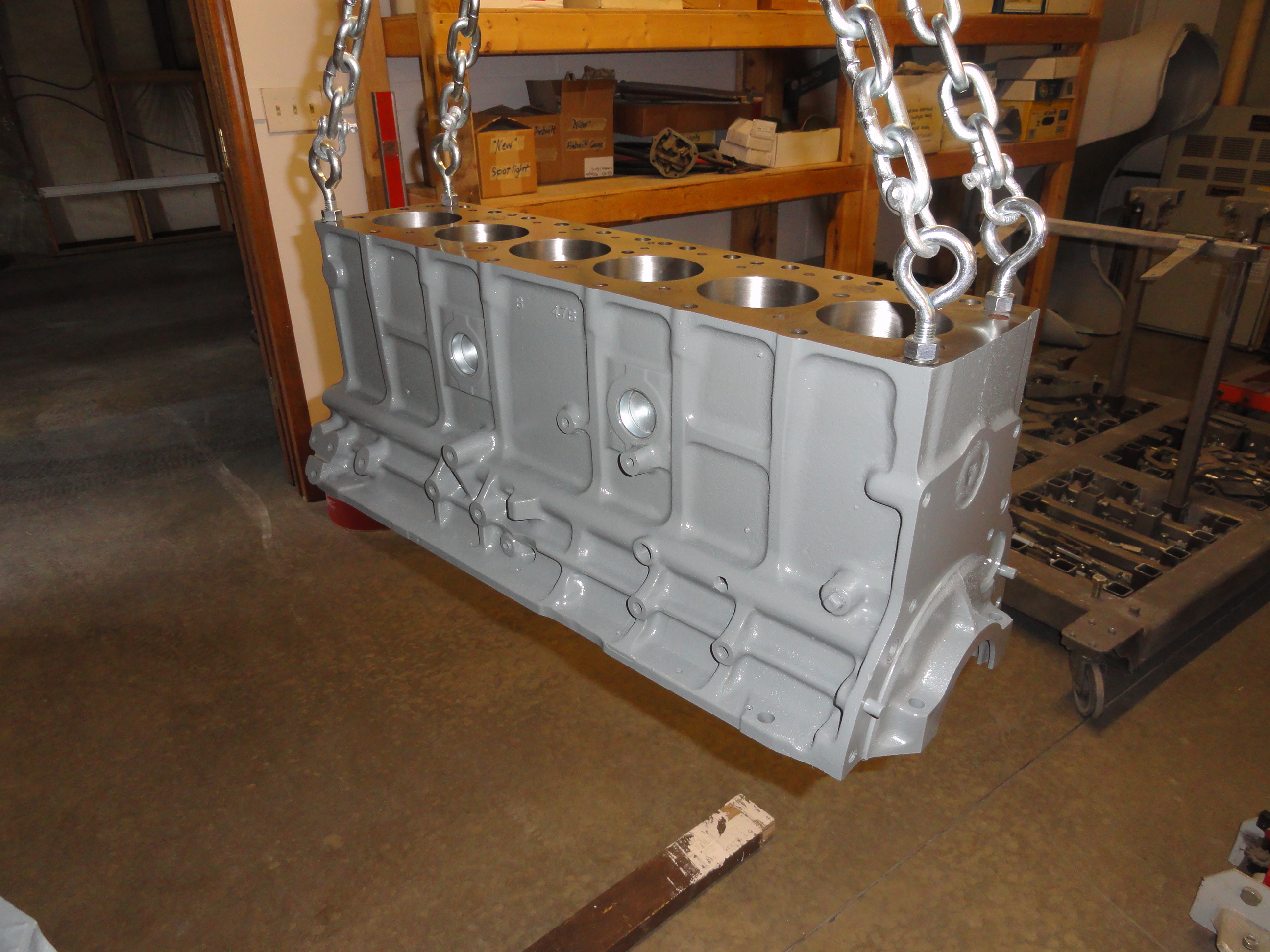
I like to make sure all freeze plugs are removed, all threaded ports open, anything that can aid in getting the internals of the engine as clean as possible. So, let's take a close look and see what we can remove to make the machine shops job a little easier. The accelerator linkage pin can be removed. We need to remove 4 freeze plugs and four oil galley plugs. To remove the freeze plugs (two in the side and two in the front) I did the same thing the Shop Manual suggested for removing the four oil galley plugs, which was drilling a 3/8" hole in the center of the plug, then pry it out with a long punch. When drilling, remember you are only interested in drilling a very shallow hole. This is important so you don't drill into a water jacket or something. In reality, there is about 5/8" between the shallowest freeze plug and the water jacket, just be aware so you don't ruin anything! The bottom right 'freeze plug' is the cover for the camshaft on that end.
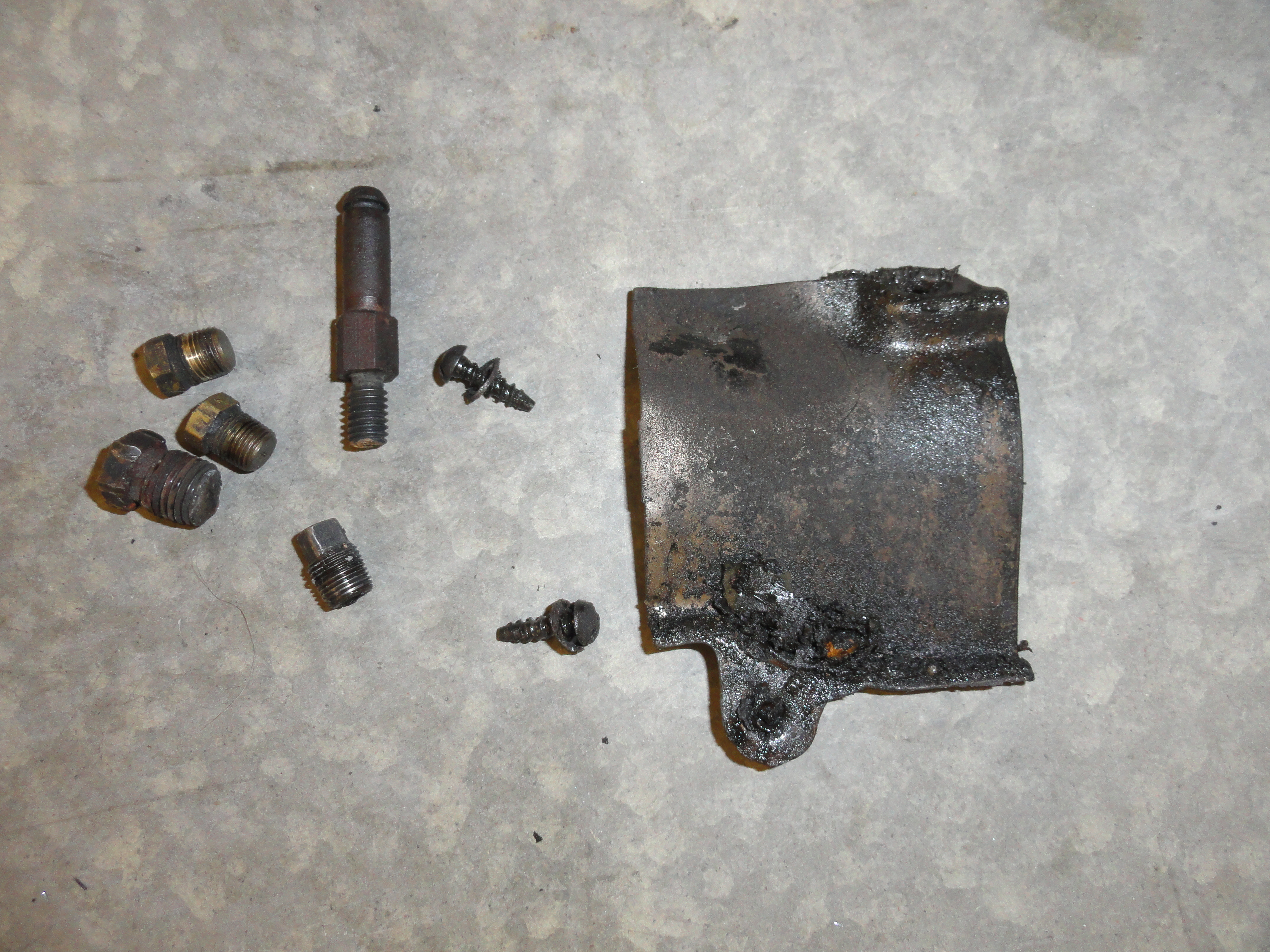
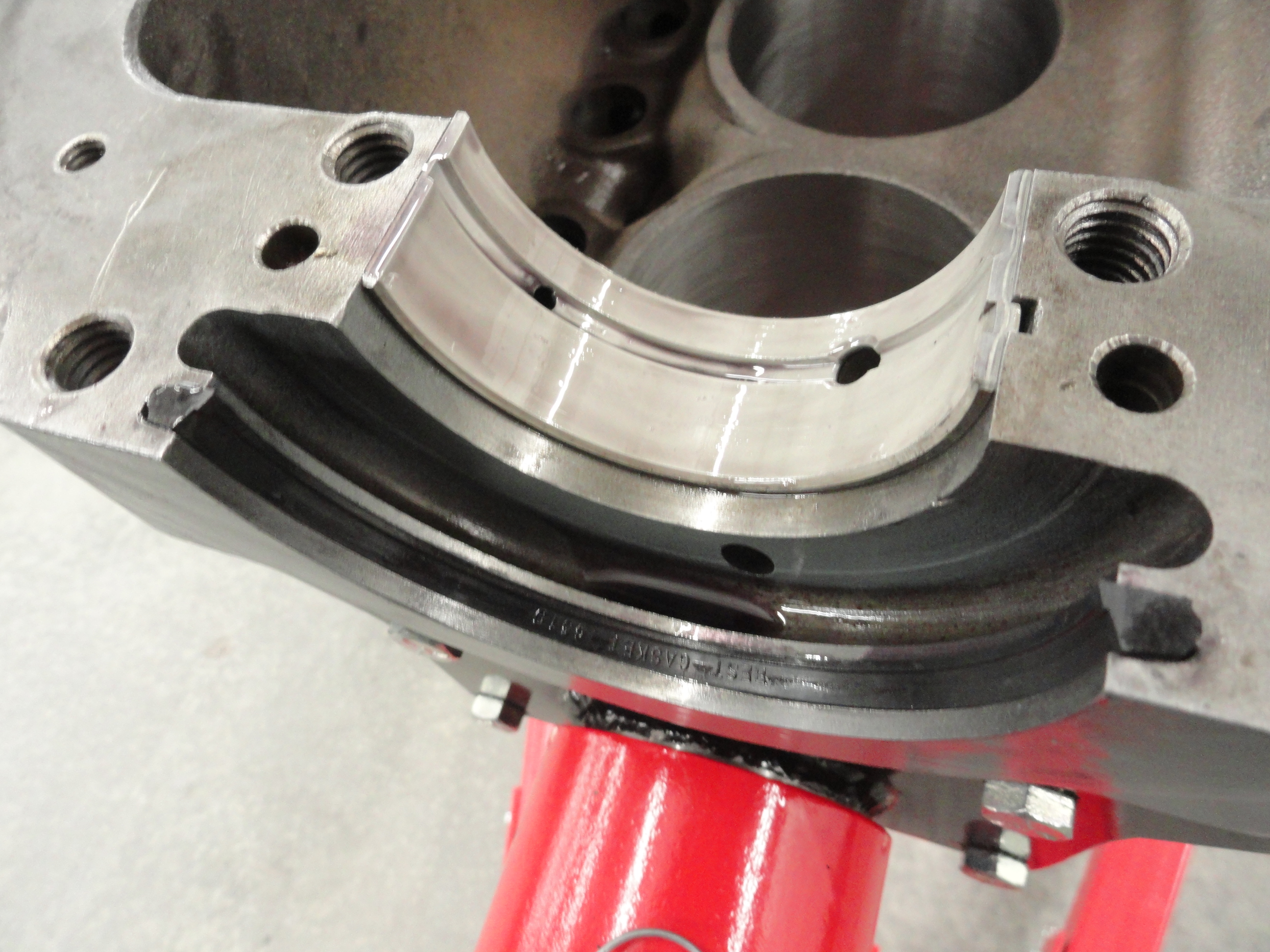
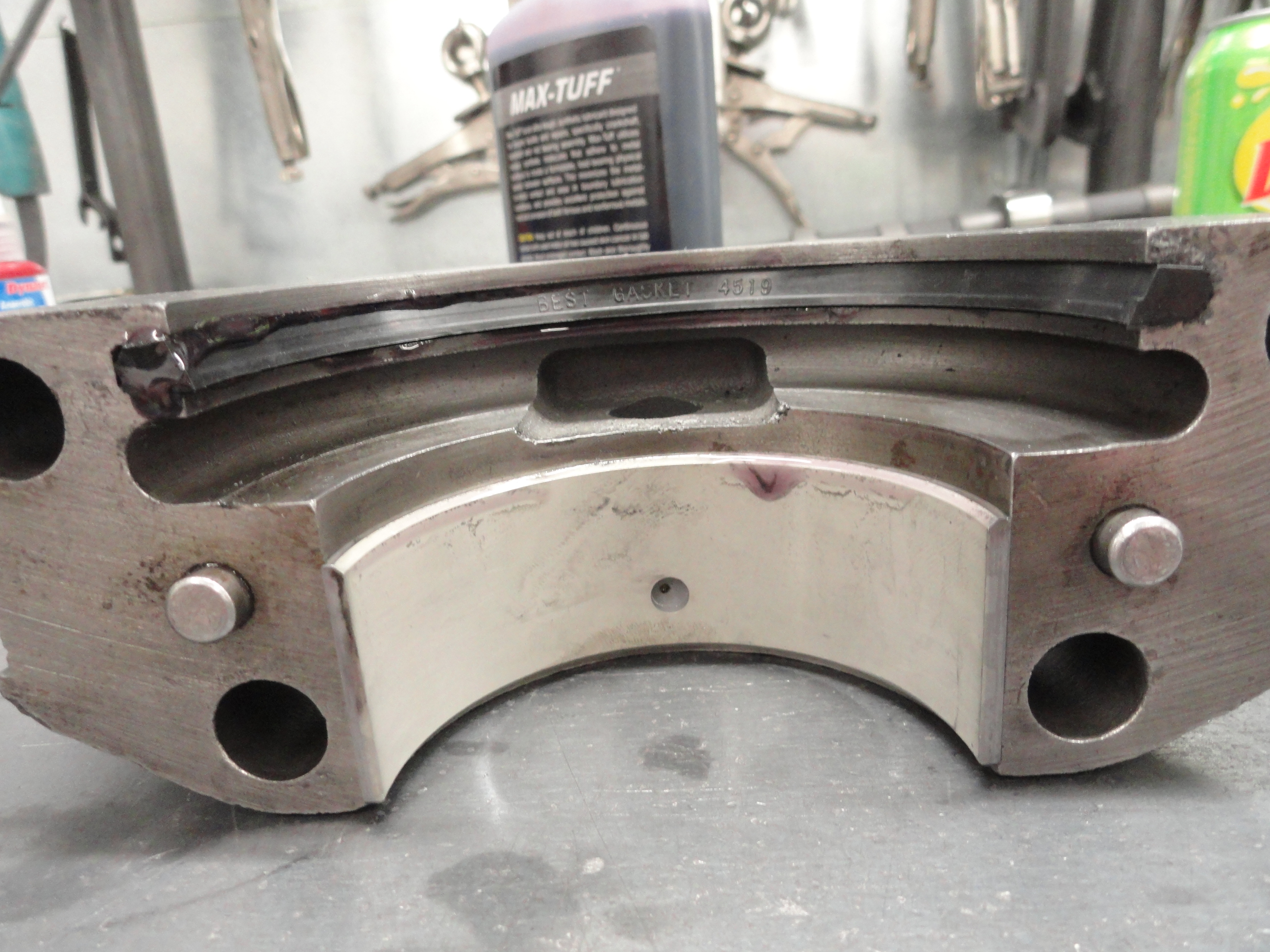
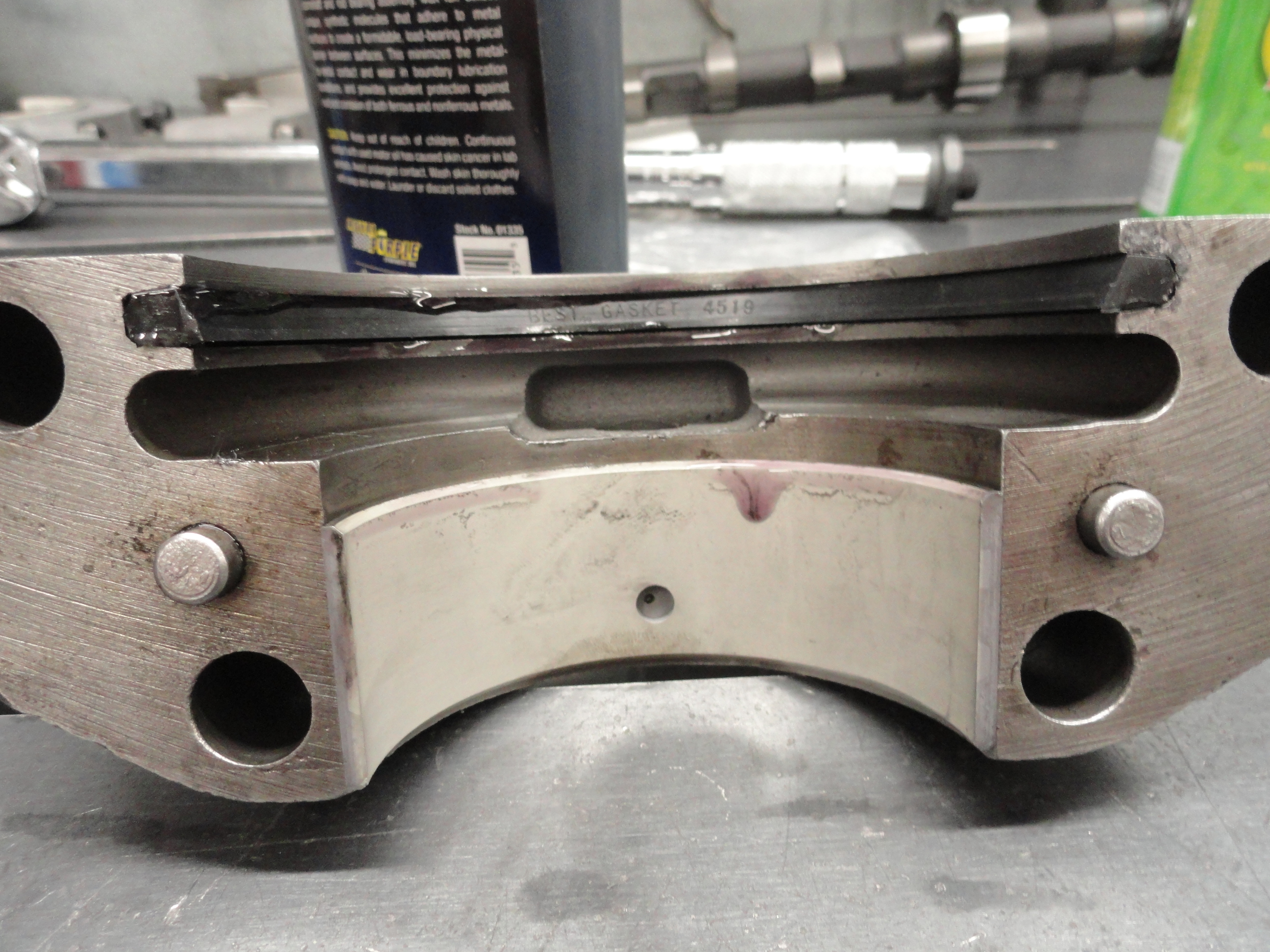
I like to have a magnet around to catch all of the metal shavings so they don't get spread all over. When prying these plugs out, do not rest your punch on the edges of the plugs. That can cause ugly gouges in the block that could make fitment a problem in some cases, so you want to use another thin piece of metal. Another freeze plug works. Anything to protect the surfaces. If the rear main seal is still inside its groove, push it out with a small screwdriver. Then, look around for all threaded plugs and remove all of them. Remove that little metal shield that is just below the road tube and is attached by two slotted screws. Take a look around the block to make sure you didn't miss anything. There should be nothing removable left. Place all the small parts, plugs, etc in a ZipLock Bag. I use brand new threaded plugs during assembly, but it's good to have them so you can account for them. That was the last thing needed before taking the block to the machine shop. It's ready to go! Let's take a look at the Head...
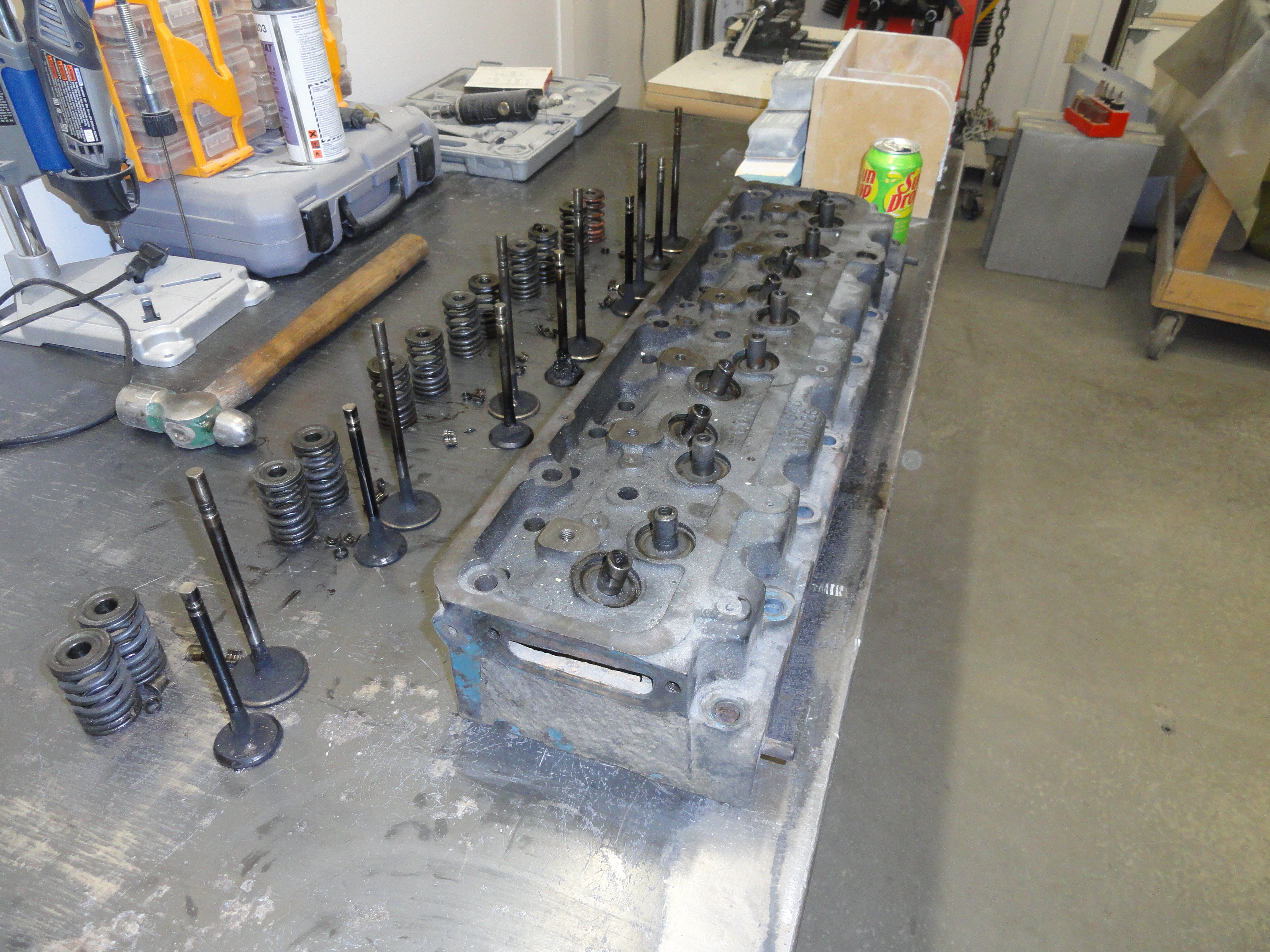
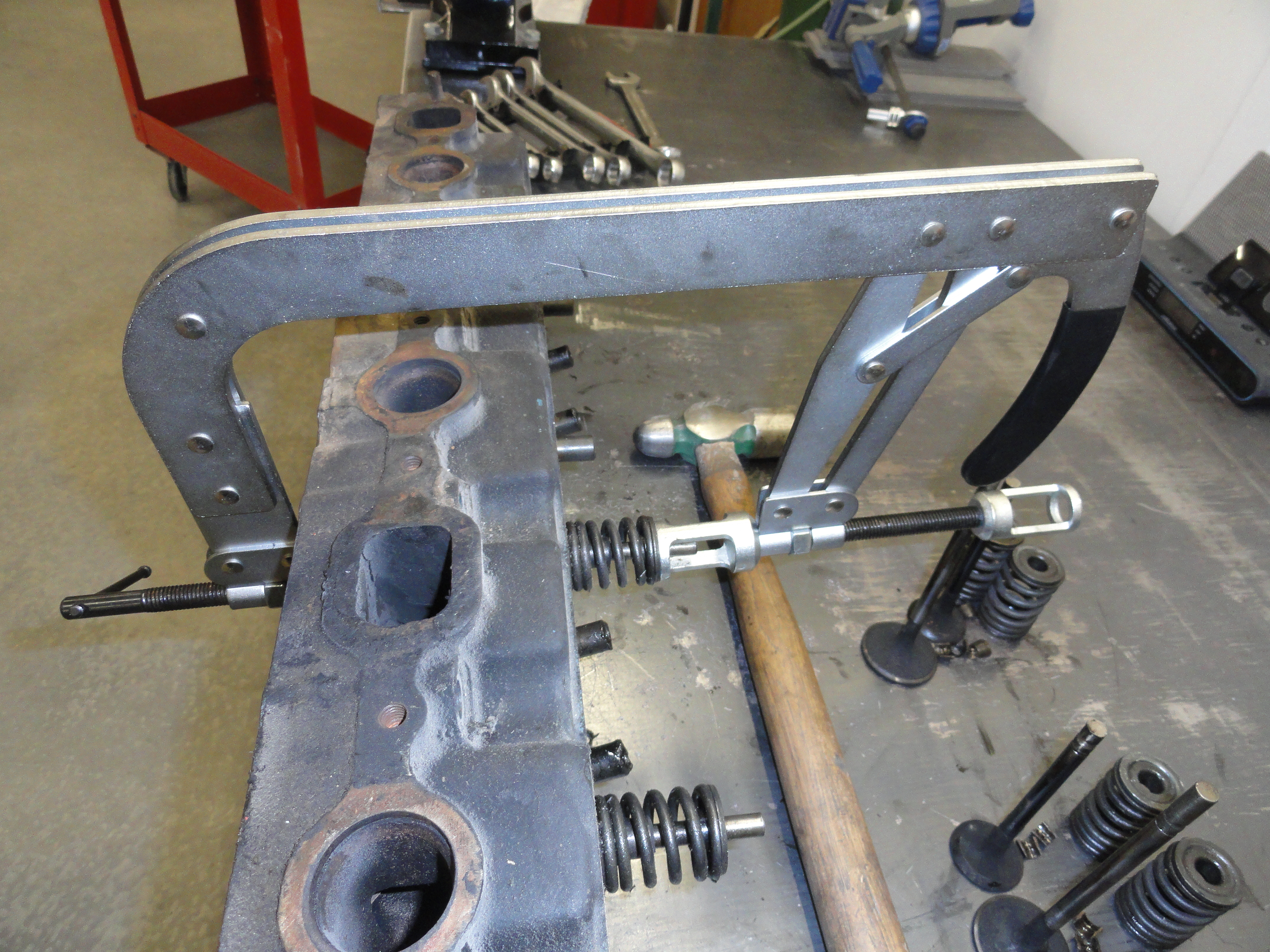
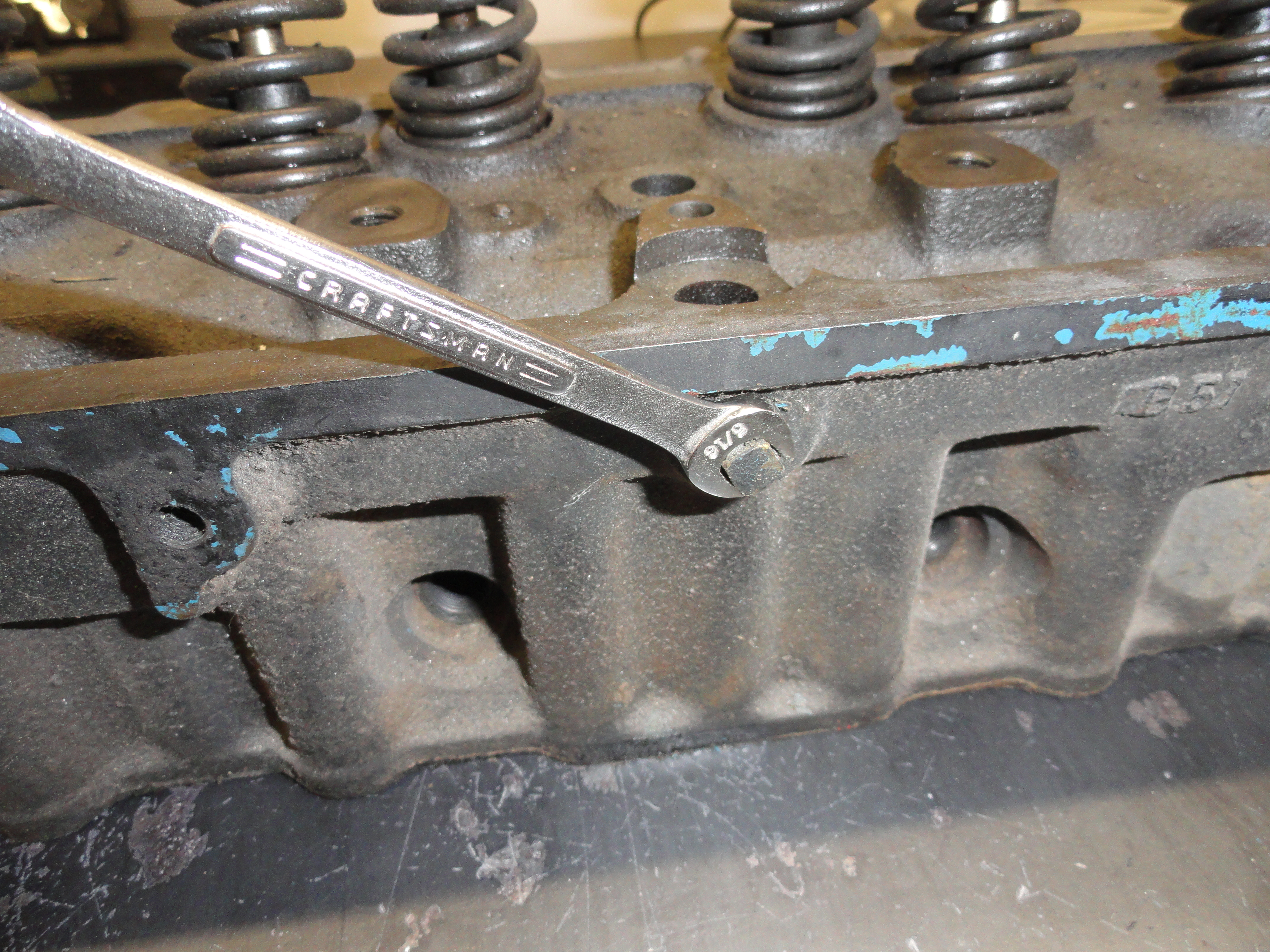
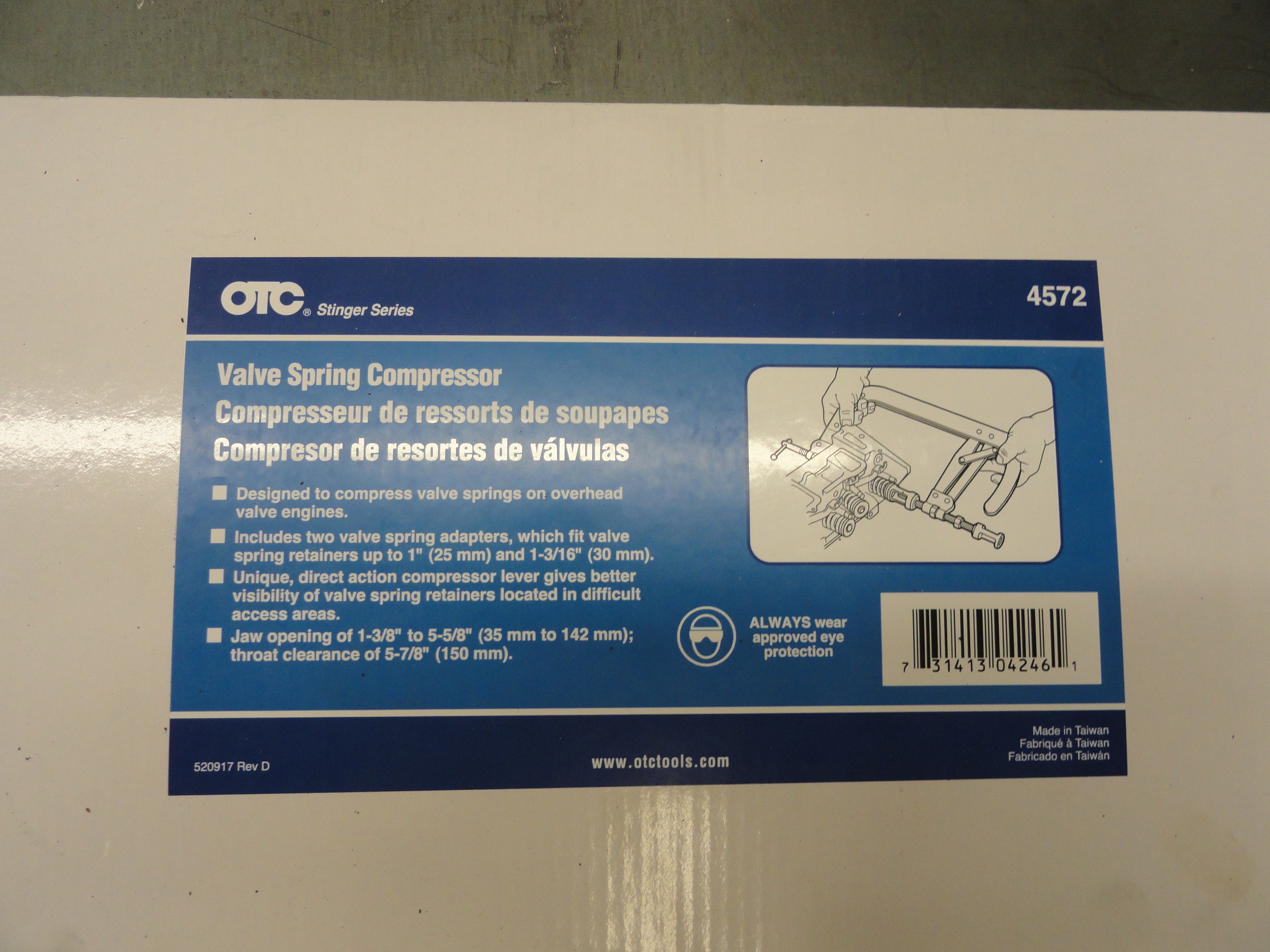
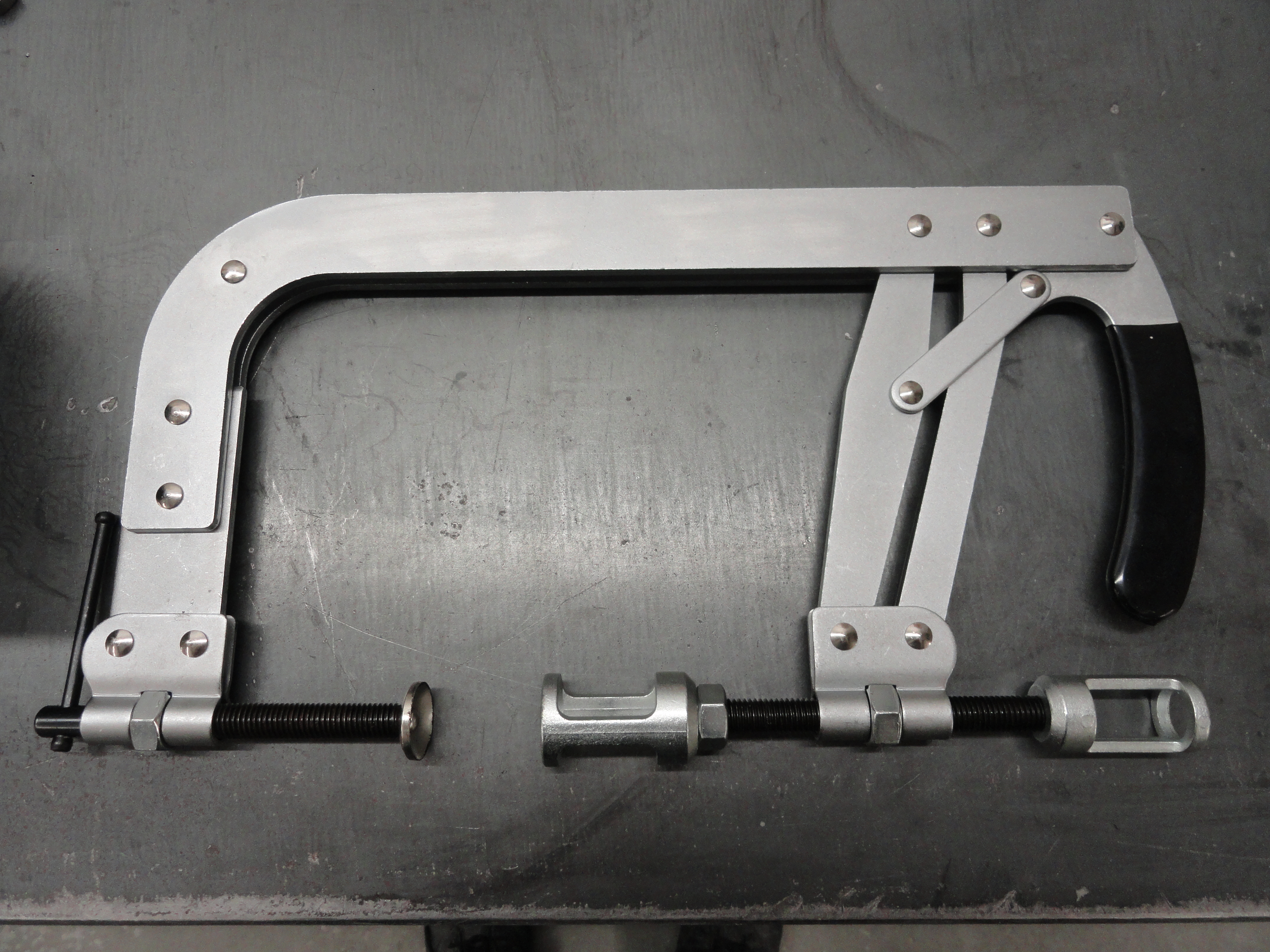
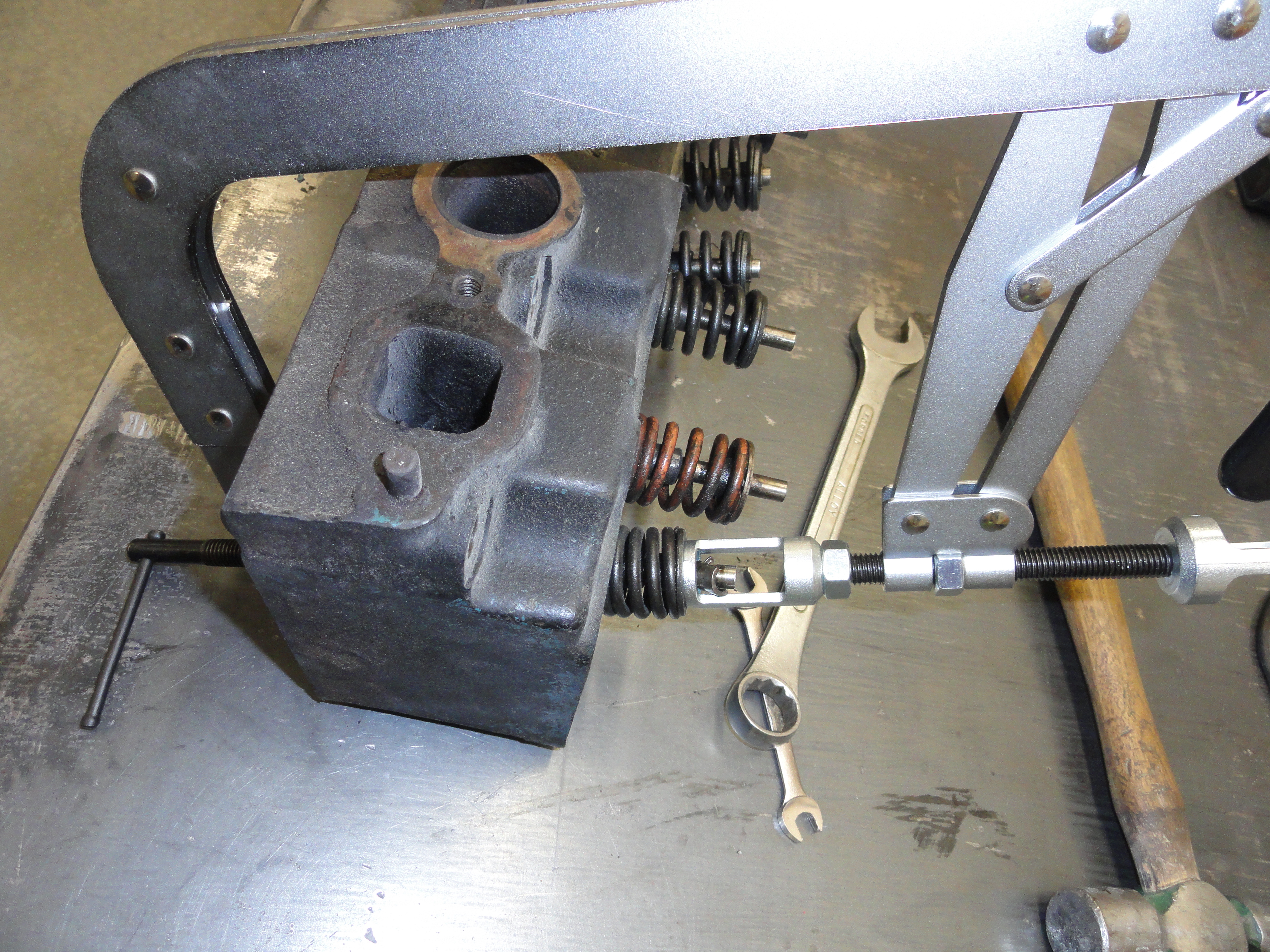
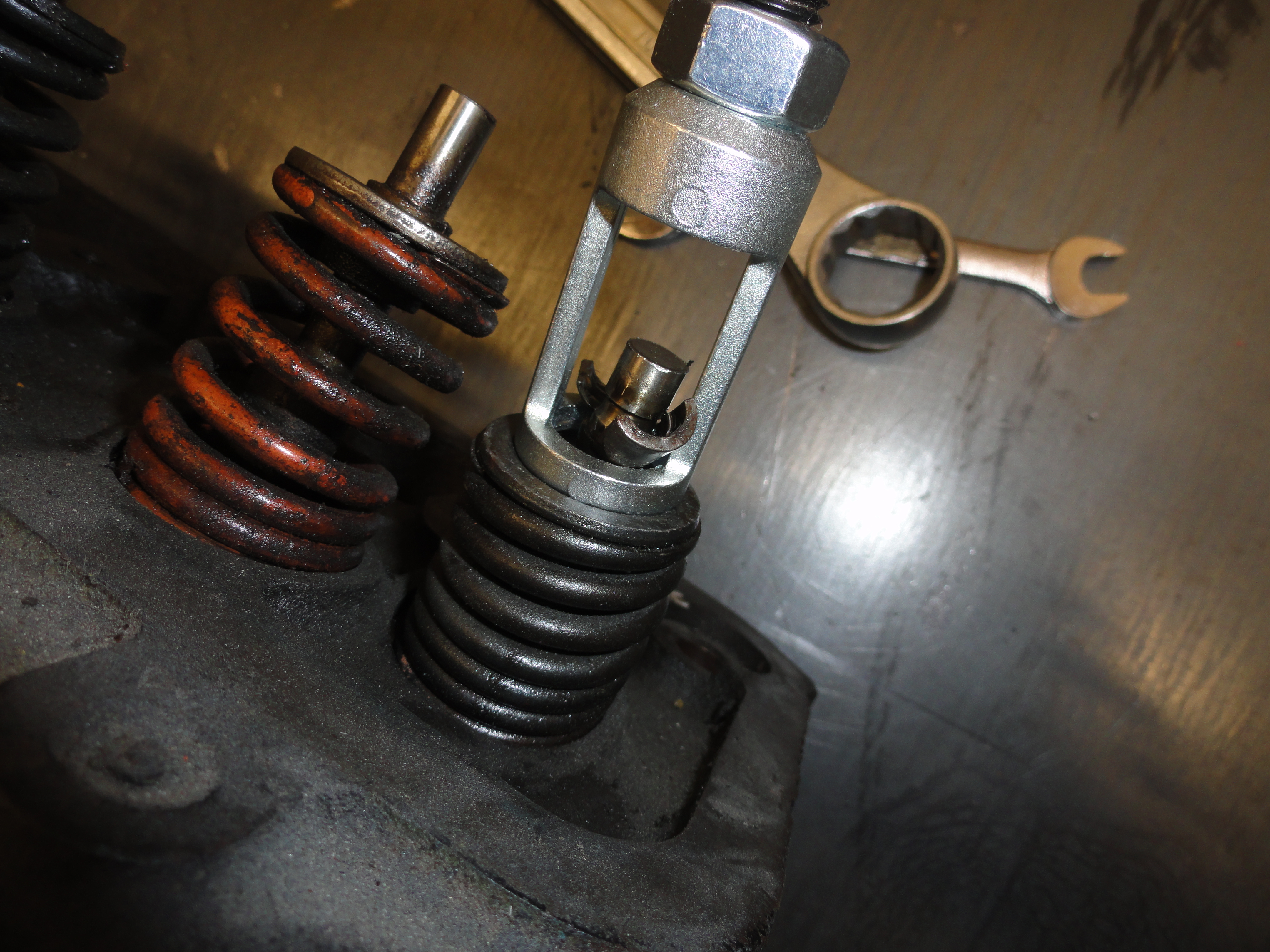
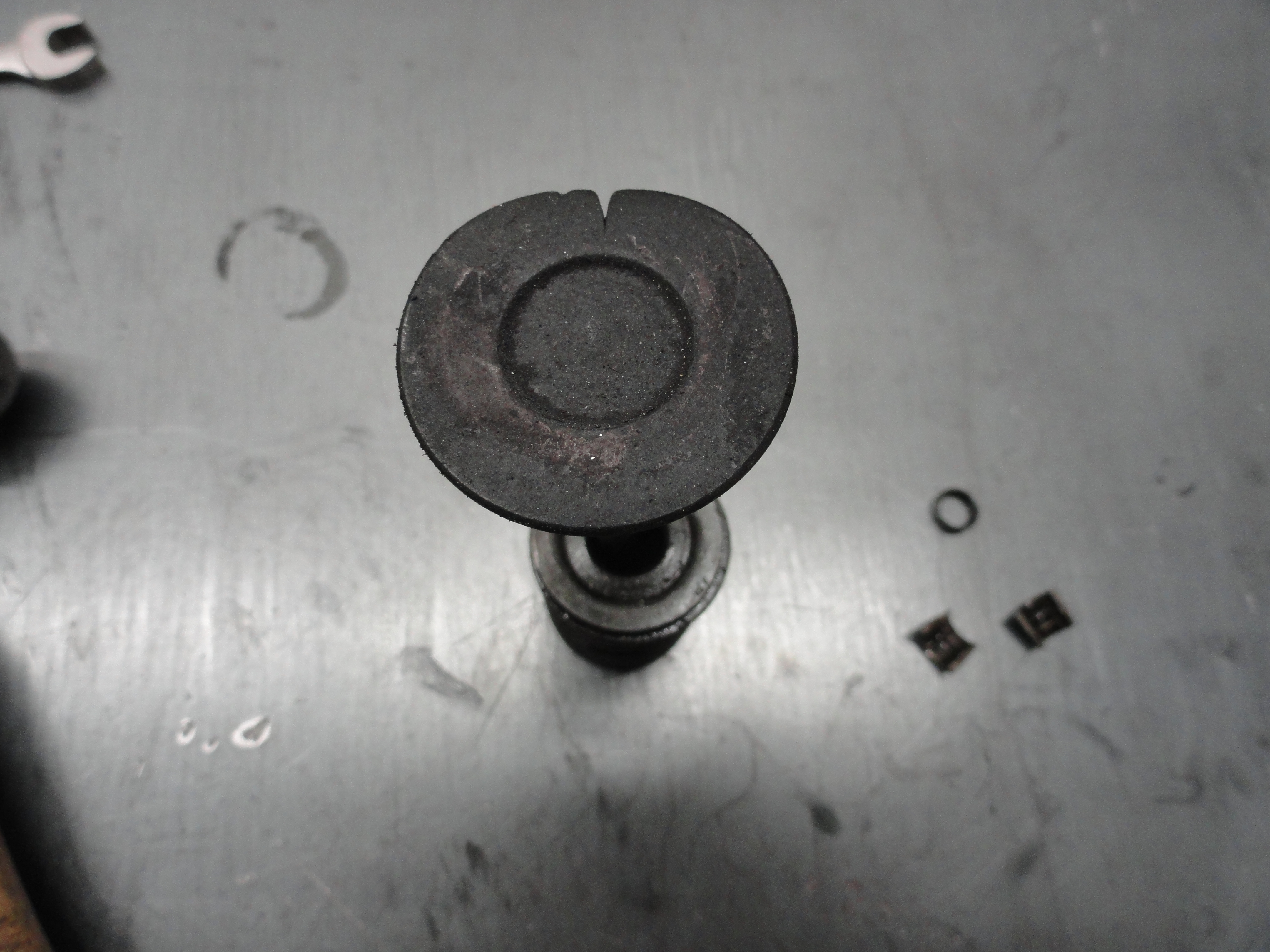
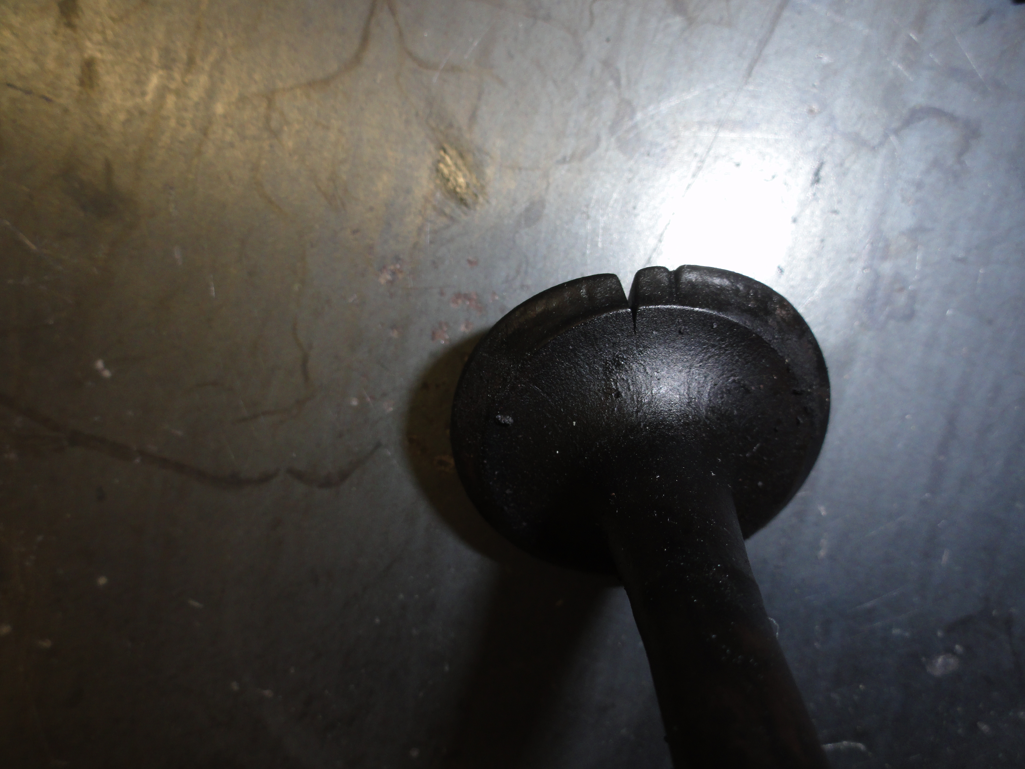
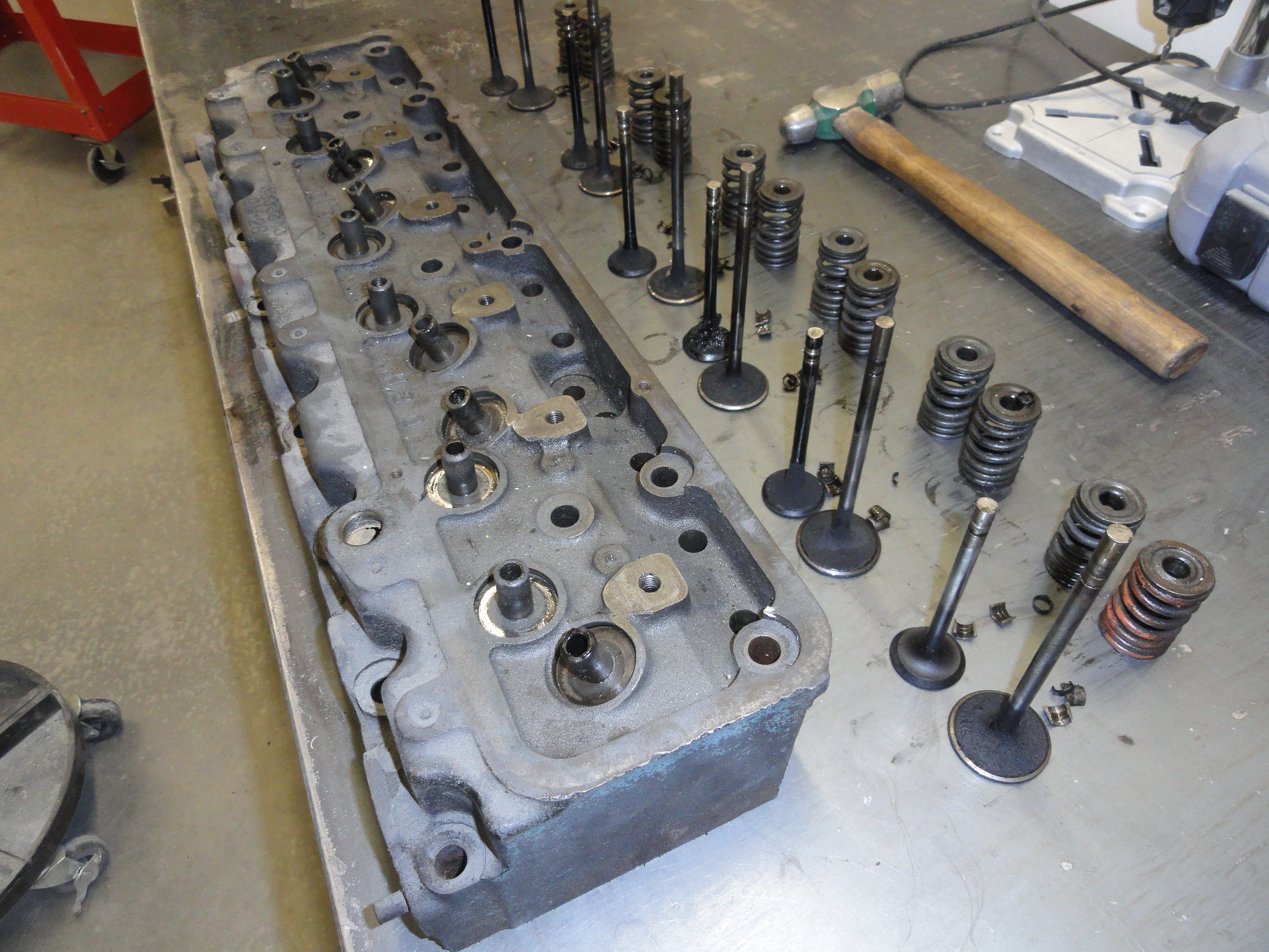
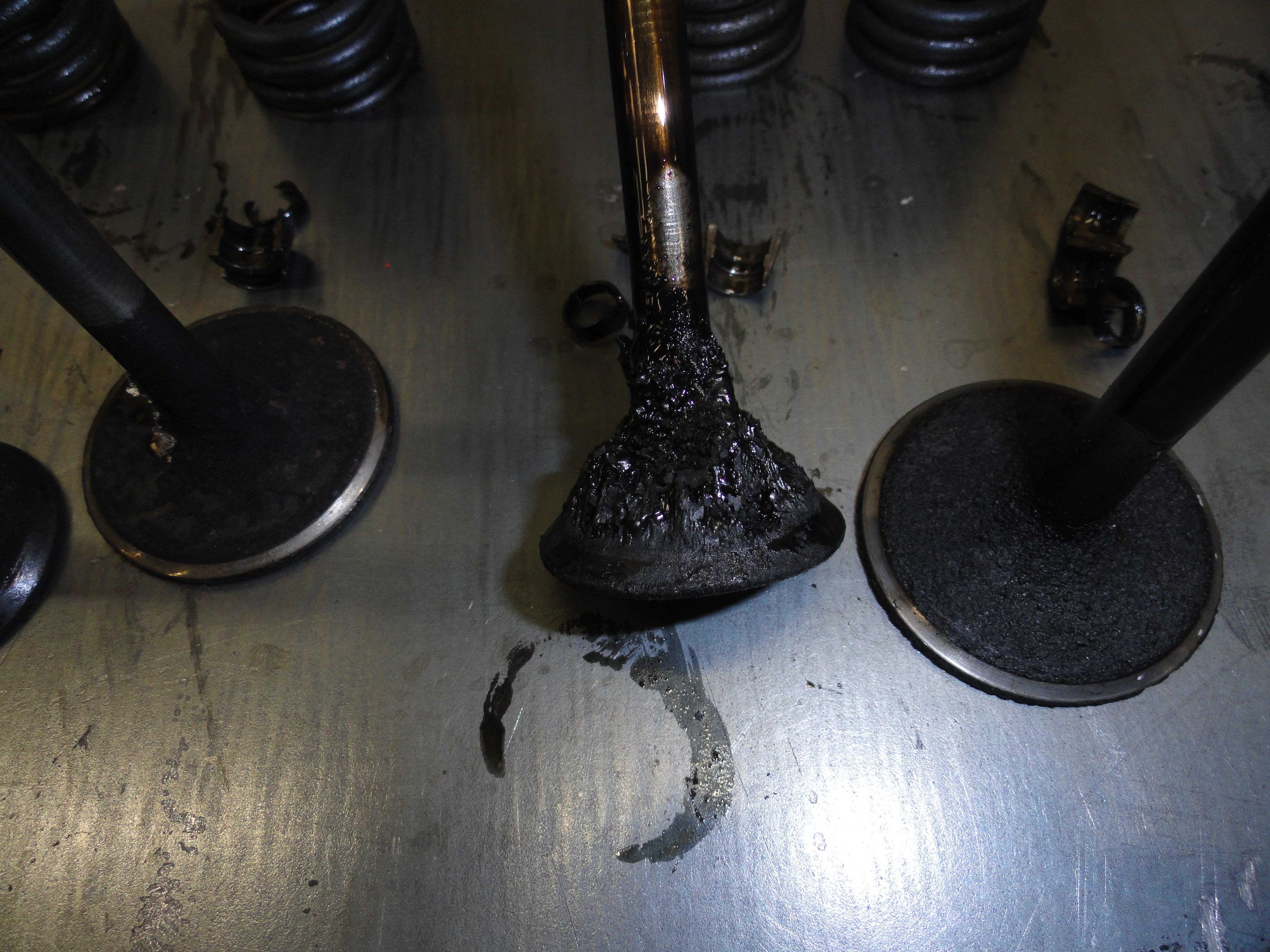
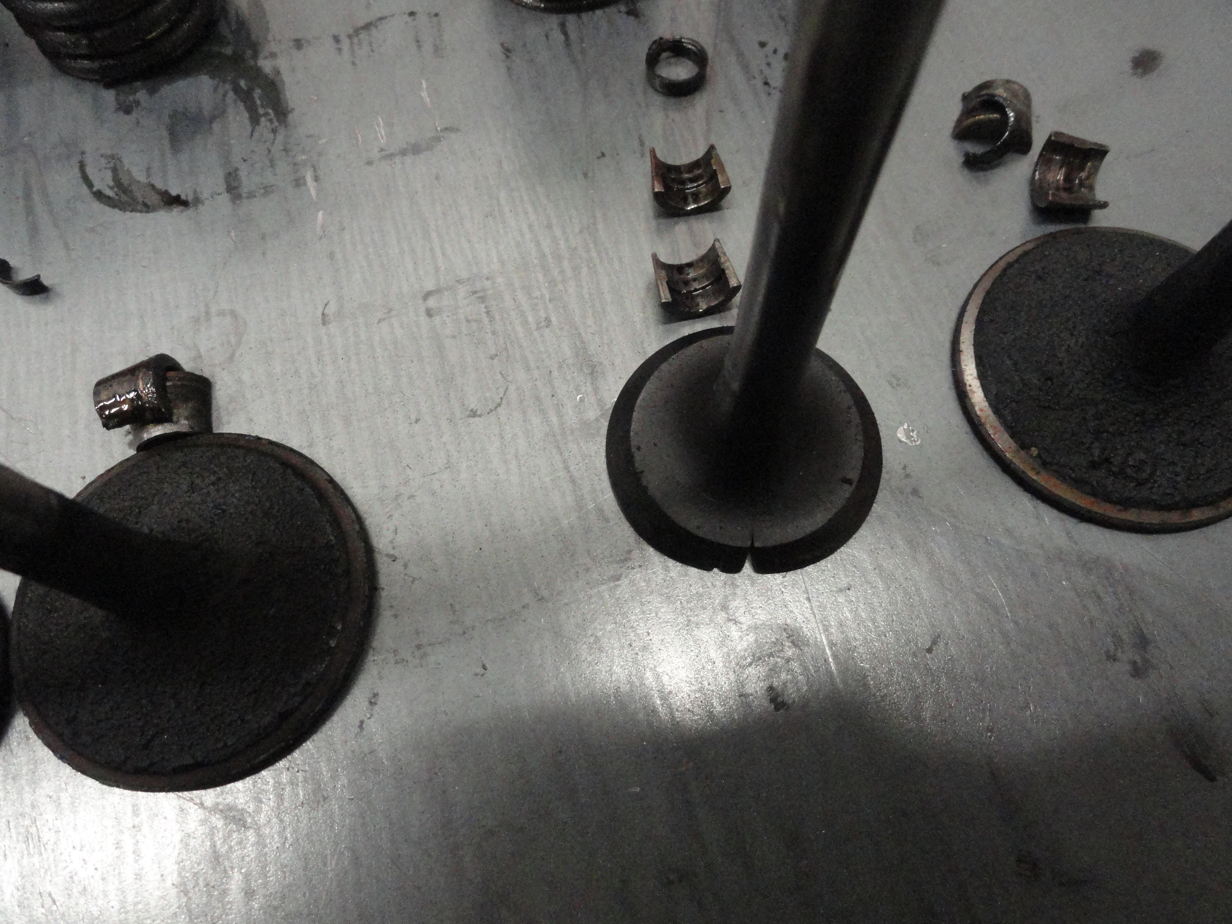
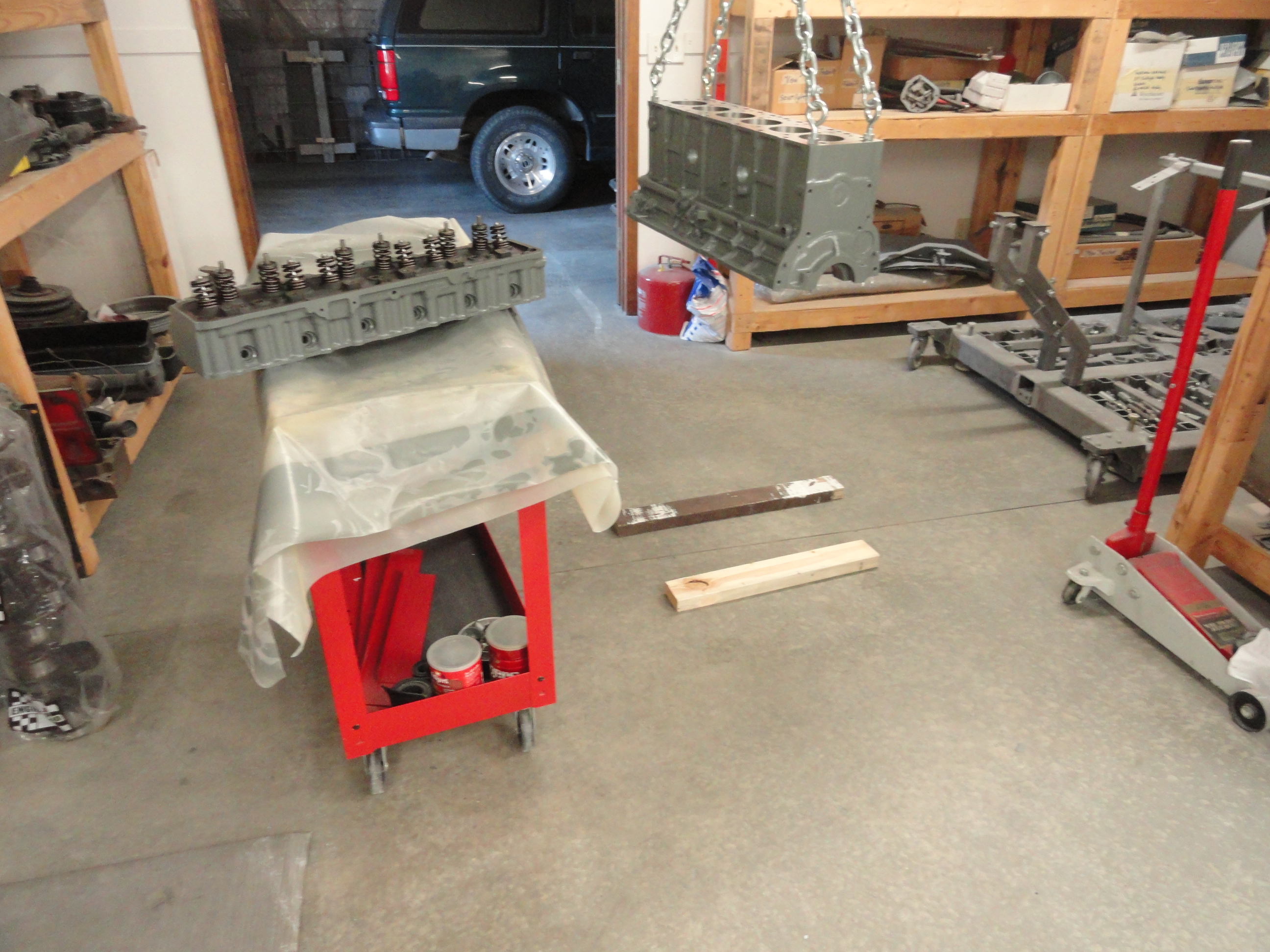
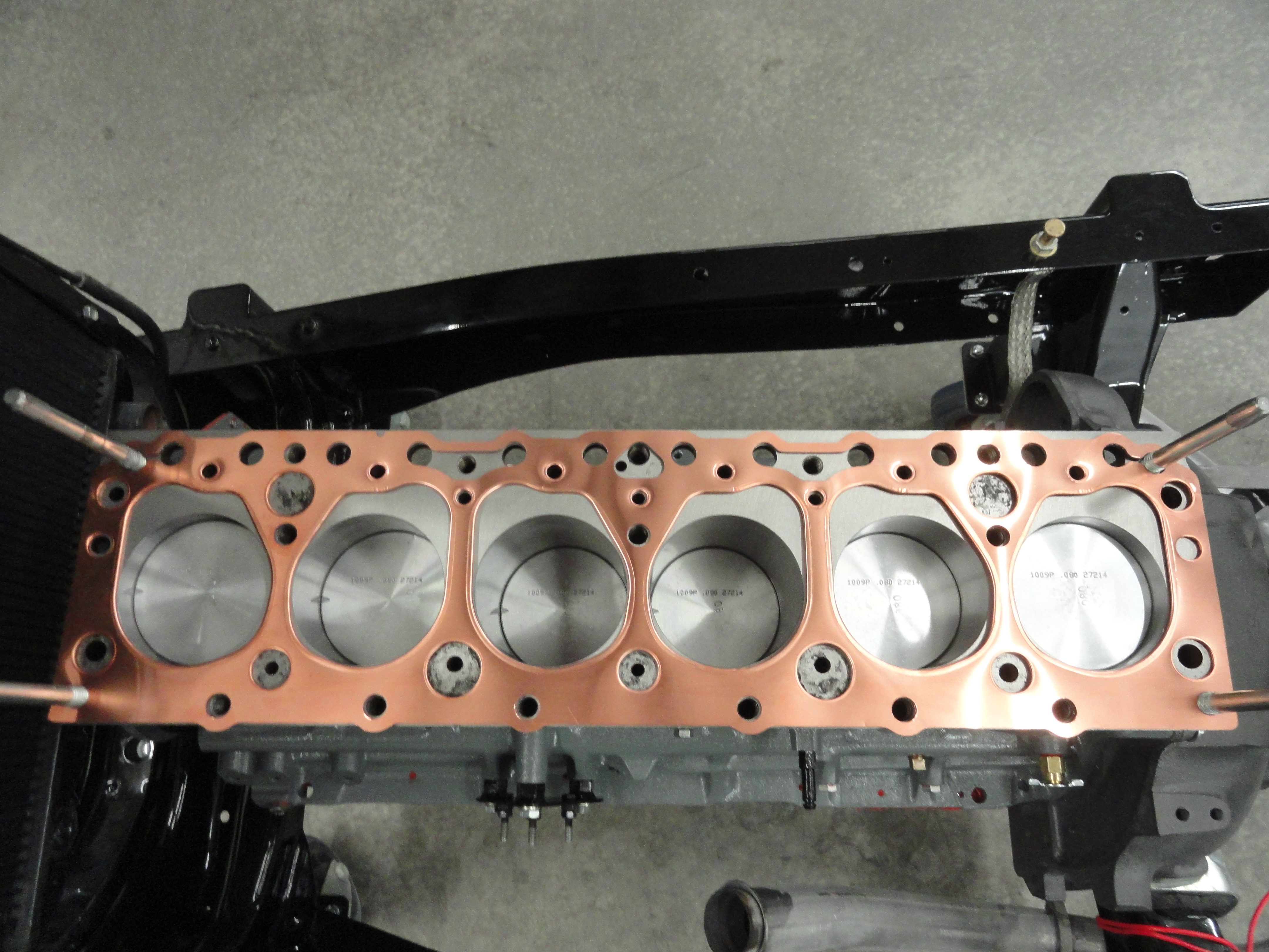
The Head needs to be addressed next. There is one threaded plug that needs to be removed and saved for later, and to make life easier for the Machine Shop, let's take the Valves out. You have to do this at least once to appreciate just how bad these Valves can get abused. To do this job, you need a Valve Spring Compressor like the one in the Tools Listing. That model works, but just barely. I would have preferred about an inch longer throat. Anyway, the pictures really tell the story. Take a look at the Out-Takes below as well. Be careful with the spring compressor. Lock the handle, then turn the crank handle making sure you are solidly on the valve on one end and centered on the spring on the other. Once you get the screw turned sufficiently, the keepers will either just fall out, or can be retrieved with a small screwdriver. Break the plastic retainer and then let pressure off the spring the same way. The spring should safely come right out and the Valve should slip right out as well. If it doesn't, I use the handle end of my hammer to tap it just a little. Again, take a look at the overflow pictures below to see just how bad this thing needed a valve job. That is it for the Head as well, so now all we need to do is box everything up and take a trip to the engine shop.
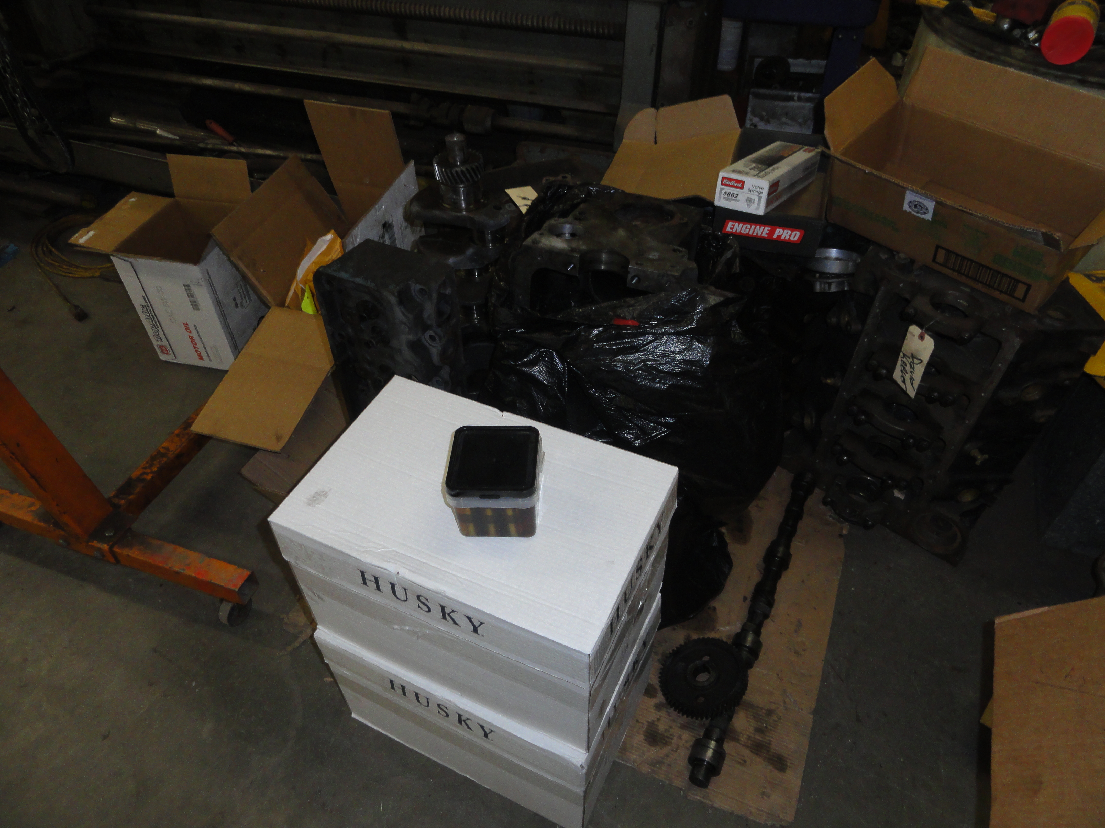
I carefully box up everything I took off the engine. I want them to inspect all the parts to determine what we can save and what we will have to purchase new. For example if the cylinders just require Honing, we may be able to keep the Pistons, but they need to be checked individually to ensure they are still serviceable. I want to ensure they have everything they need. There are some parts I have questions about, such as the Hydraulic Lifters. Write down all of your questions and make a list of things you want them to do. The things on my list, for example are:
Then you if you want them to do special work, you have to tell them exactly what that may be. In my case, I have a few things on my wish list.
These are things I am either uncomfortable doing myself, or feel the job would be done more competently by the machine shop. The extra
cost of them putting in the freeze plugs for example is minimal and since this is a possible source of leaks, why not let the pro do it?
Cam Bearings are pressed in and if you don't have a good way of doing this, just ask them to do it. The Crank getting drilled for a bolt serves
two purposes.. it will ensure the Balancer won't slip off but it also gives me the ability to turn the engine with a break-over bar during
timing and setup. Between that and the fact that there are horror stories out there about people's pressed on Harmonic Balancers coming off
at highway speed, it just seemed prudent.
The engine, head, crank, cam, lifters and 2 full boxes of engine parts are all at the machine shop. They have instructions to inspect
everything that would have an impact on tolerances and machine work. When Jim Keever (Engine Shop owner) saw what I was doing with this
article, he offered to take pictures at each step! Nothing better than cooperation in the mission of helping others!
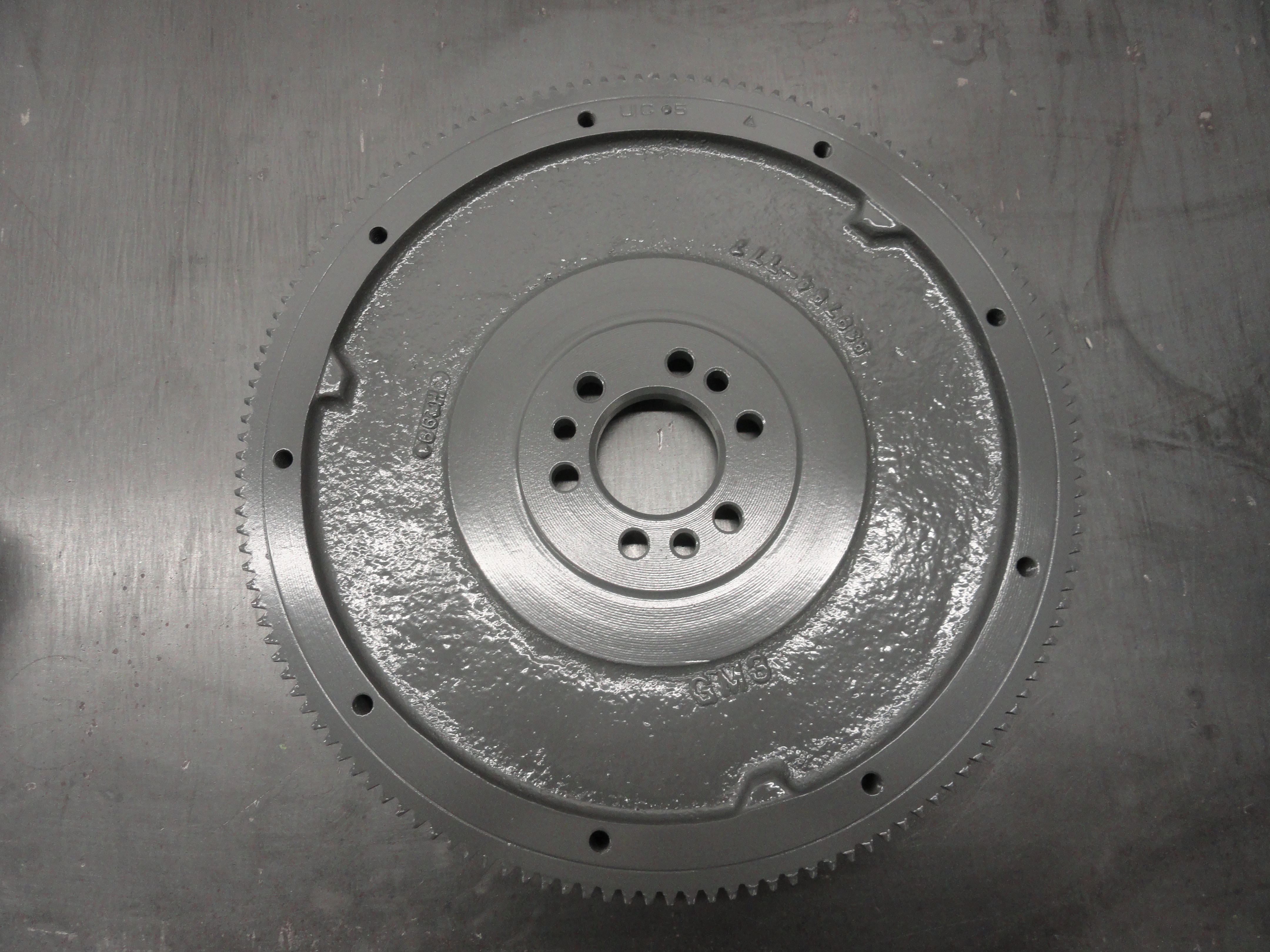
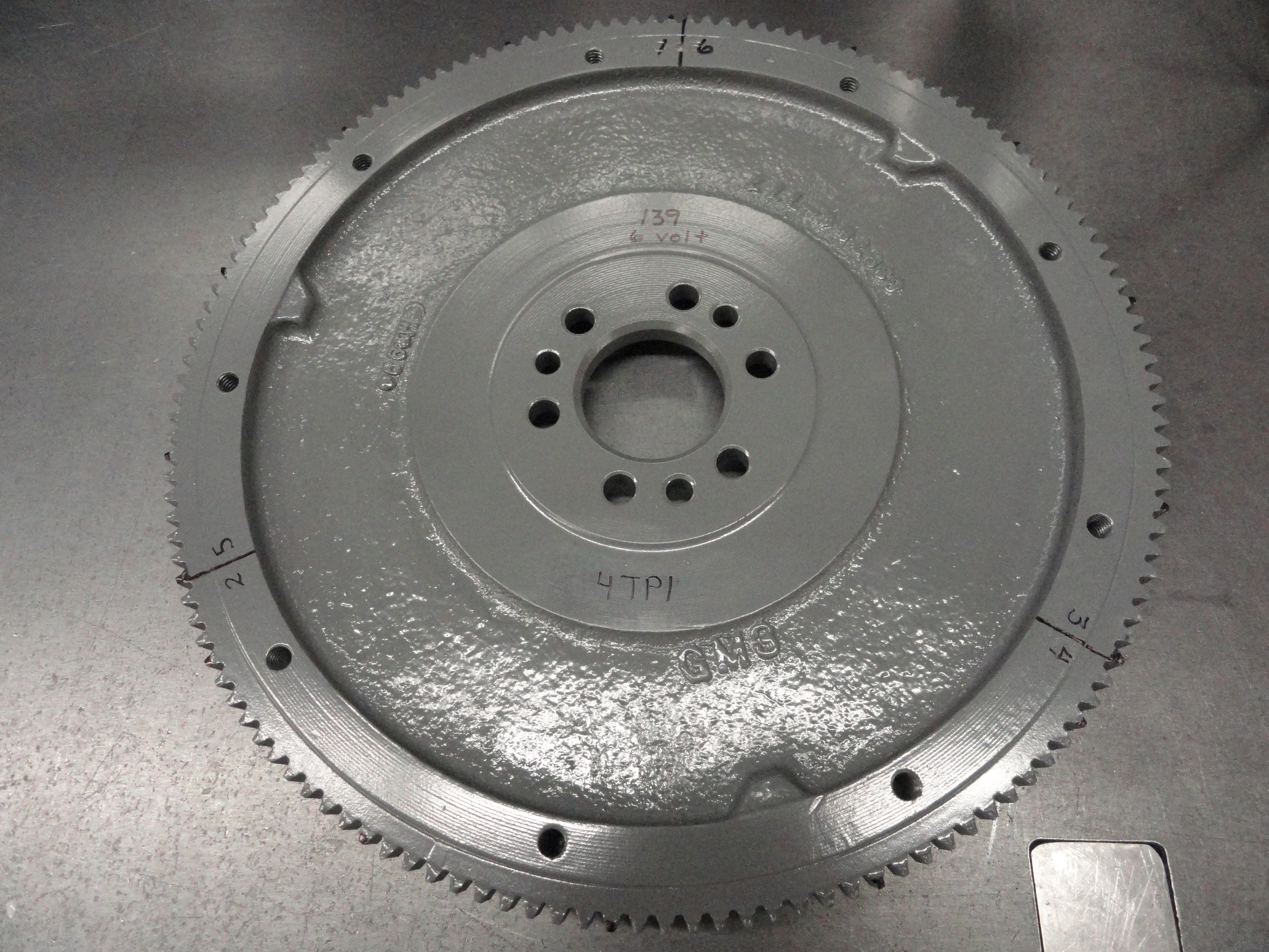
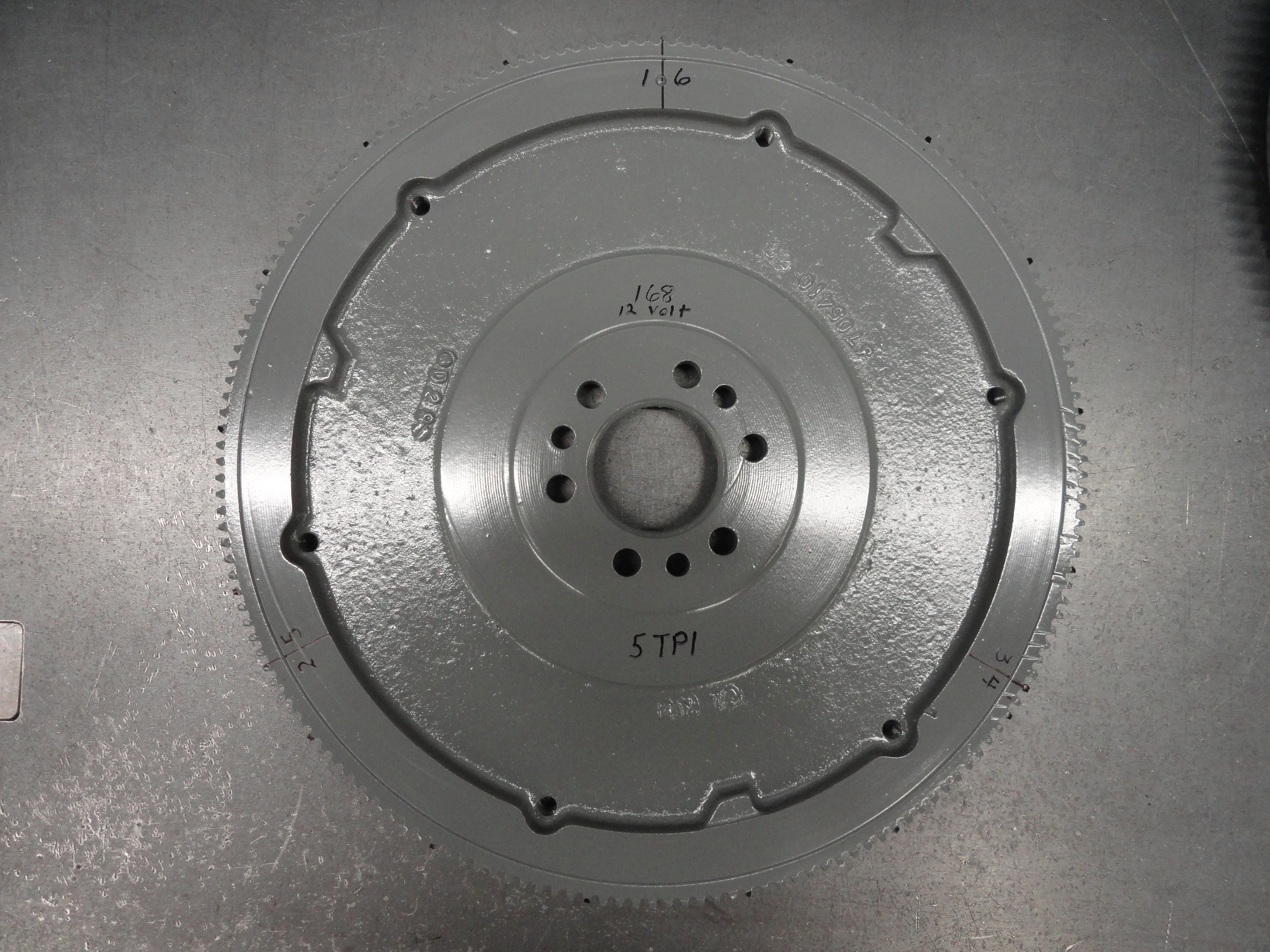
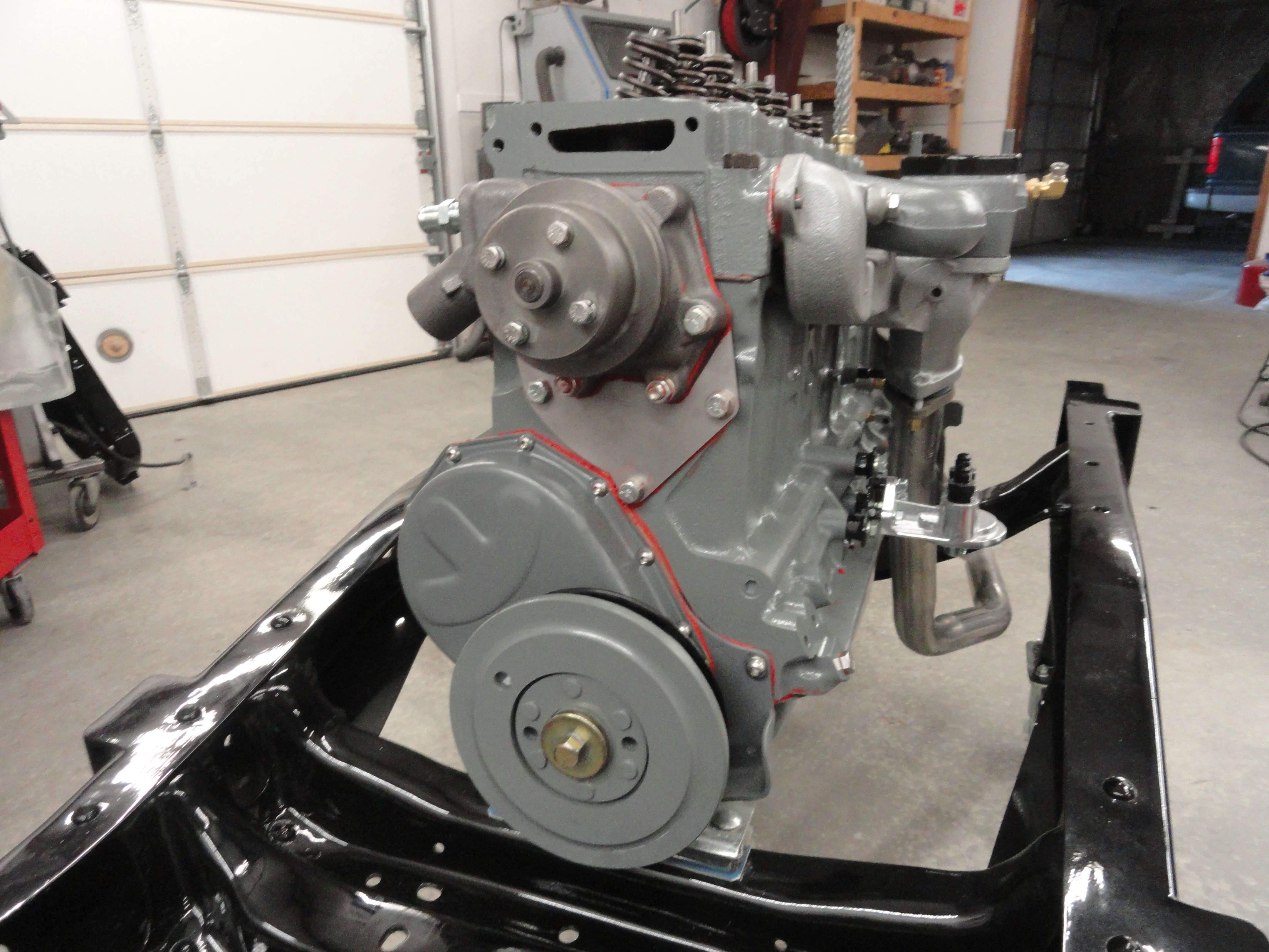
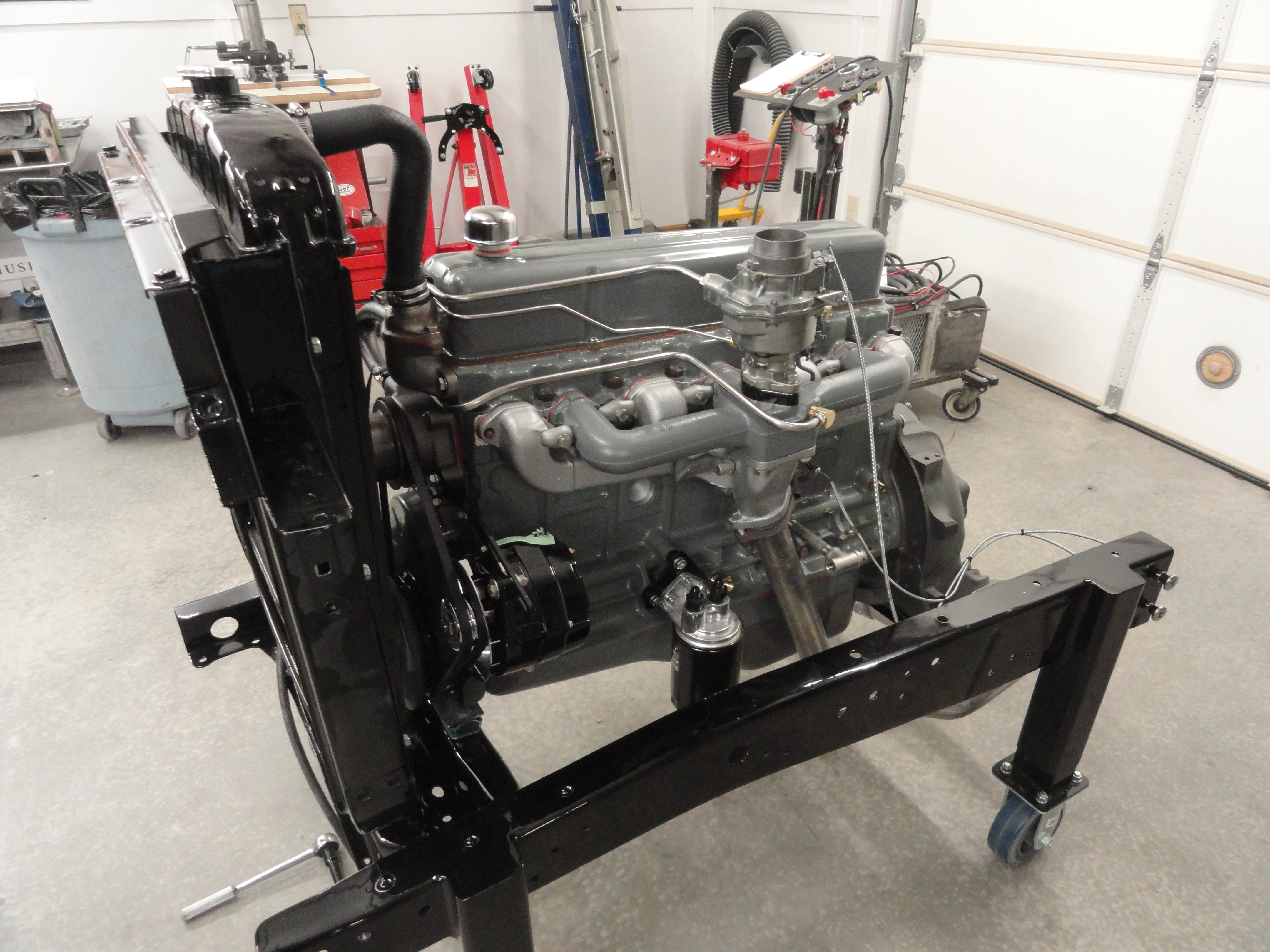
There is much more to do to prepare for this engine to arrive back in my shop. We need to address all of the engine sheet metal, each individual system needs to be completely refurbished. The old rusty bolts will be replaced with a stainless steel engine bolt kit. You may feel this is overboard, but for $50, well worth it. Think about this bolt issue for a second. You can't sandblast the old ones or even deep clean them because the CAD plating has been compromised years ago. If you use the old bolts after cleaning them anyway, they will rust very quickly. The exception is the Head Bolts and Flywheel Bolts because I feel hardened steel is preferable to stainless. You can get new Head Bolts or clean up the old ones. I purchase new Zinc Plated flywheel bolts. Lastly, you can sandblast all of your old bolts and take them to a Plating company. I am not sure if you will get away with paying less than $50. If you do decide to get your bolts piecemeal perhaps from a hardware store, look carefully at the bolt heads and be sure to get the proper strength bolts.
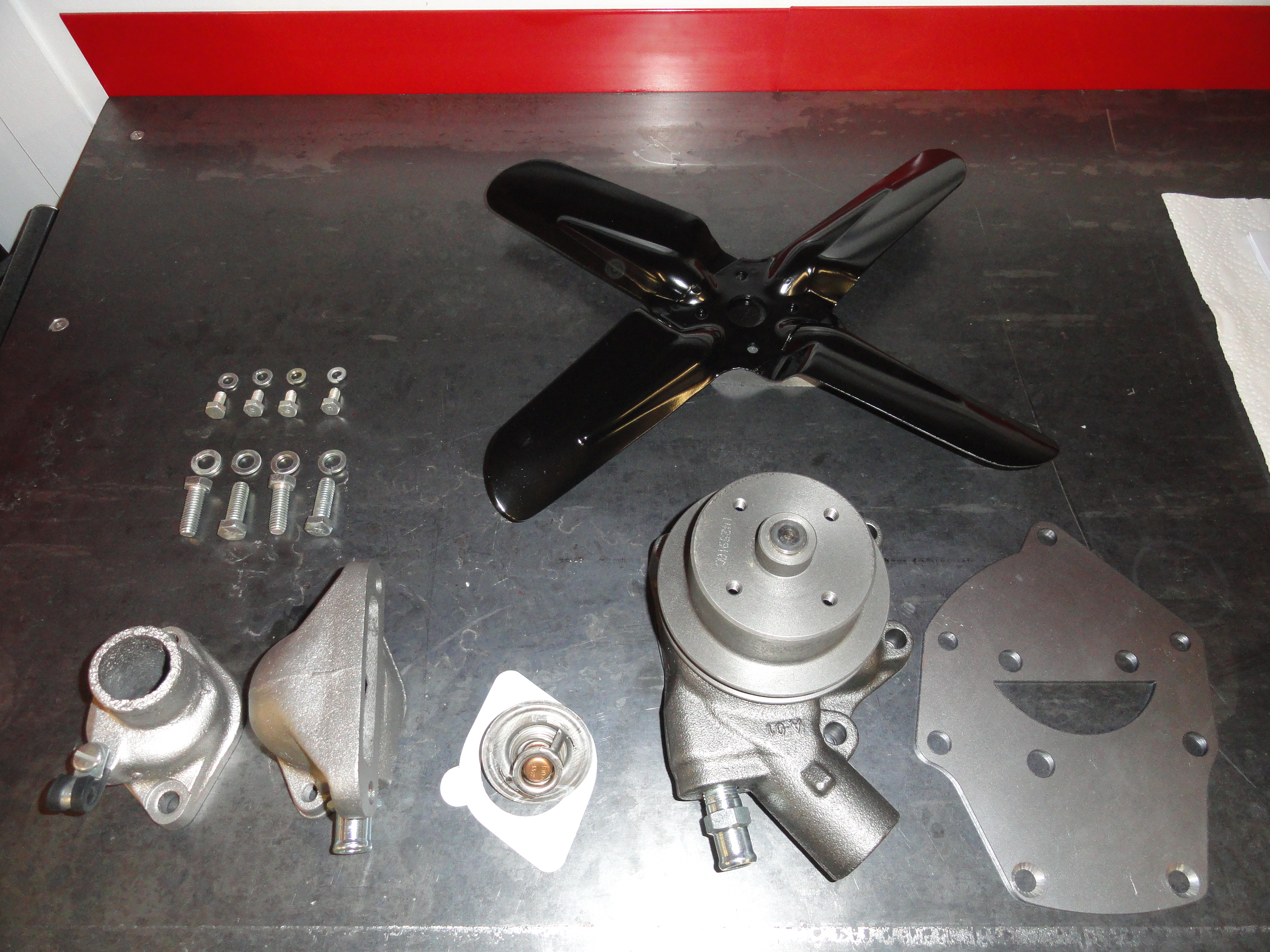
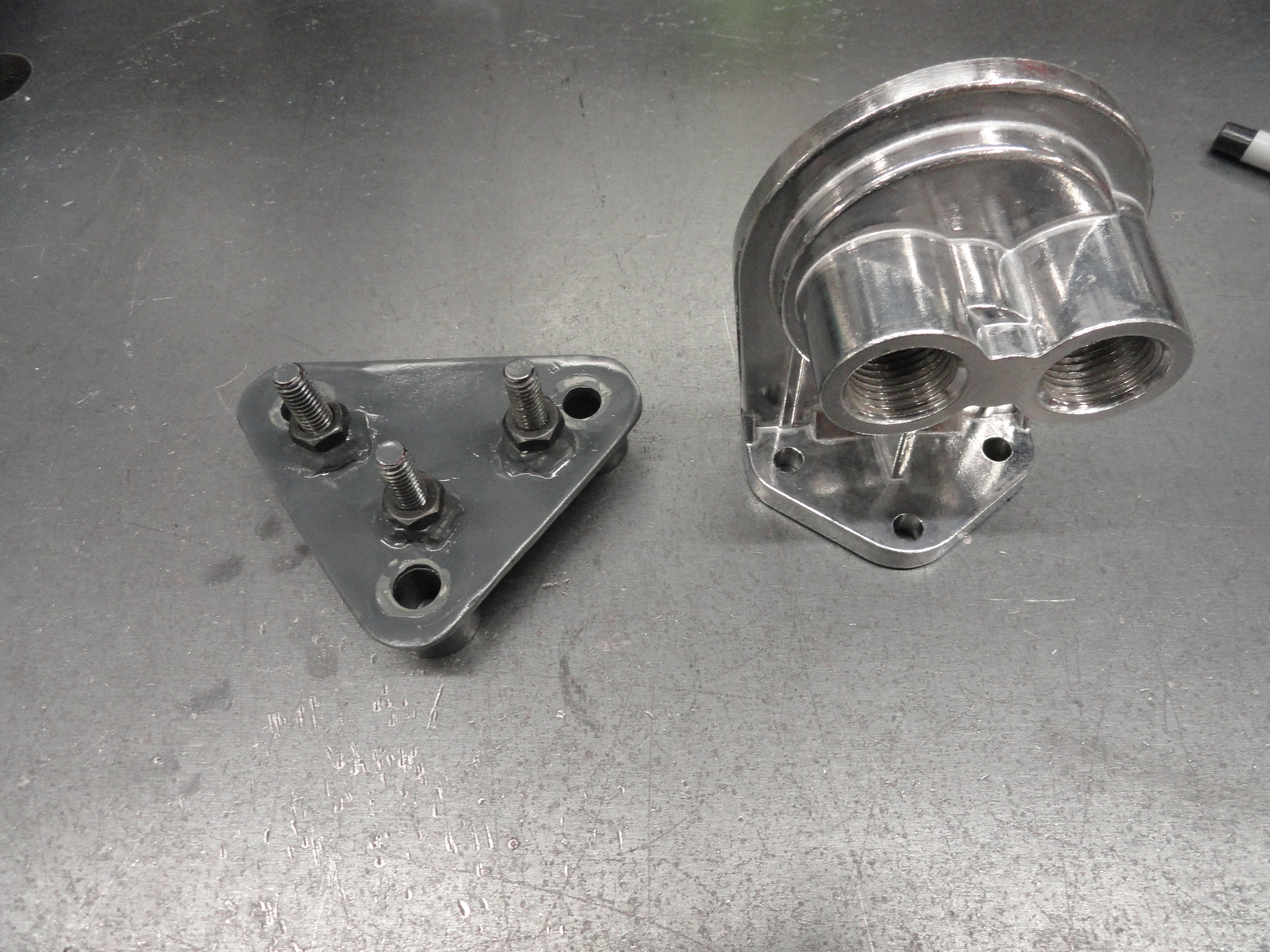
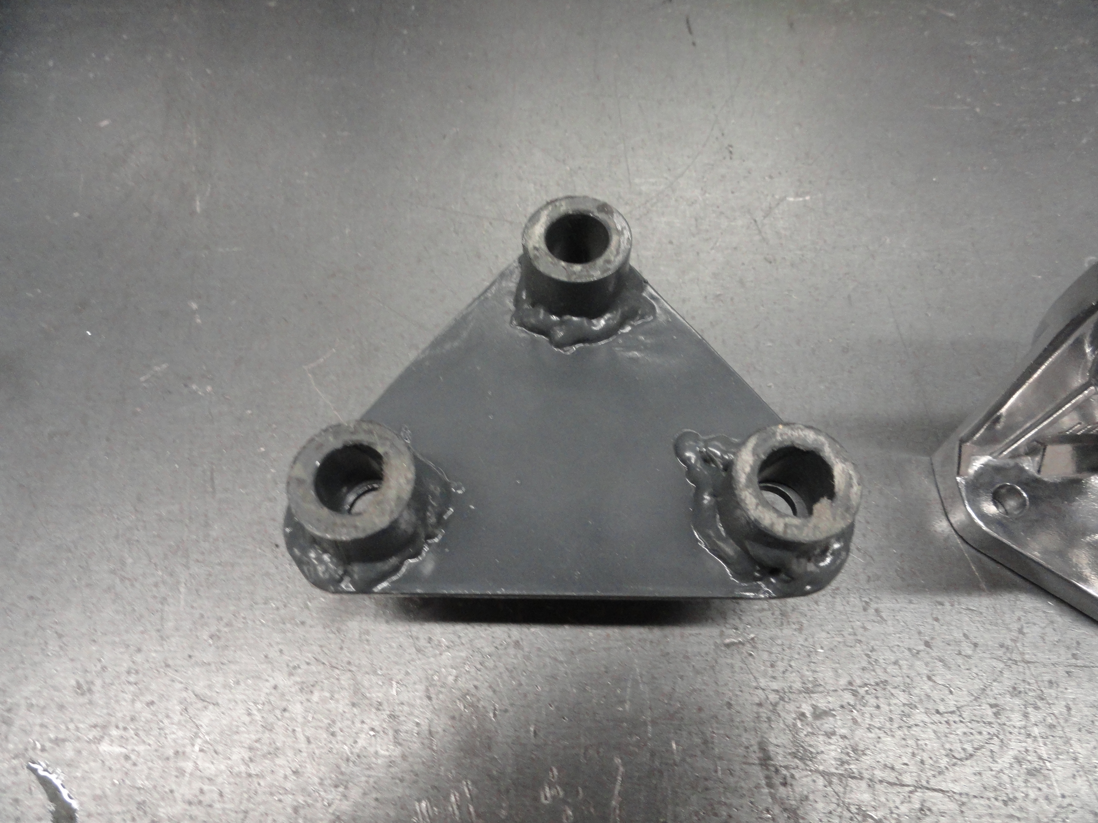
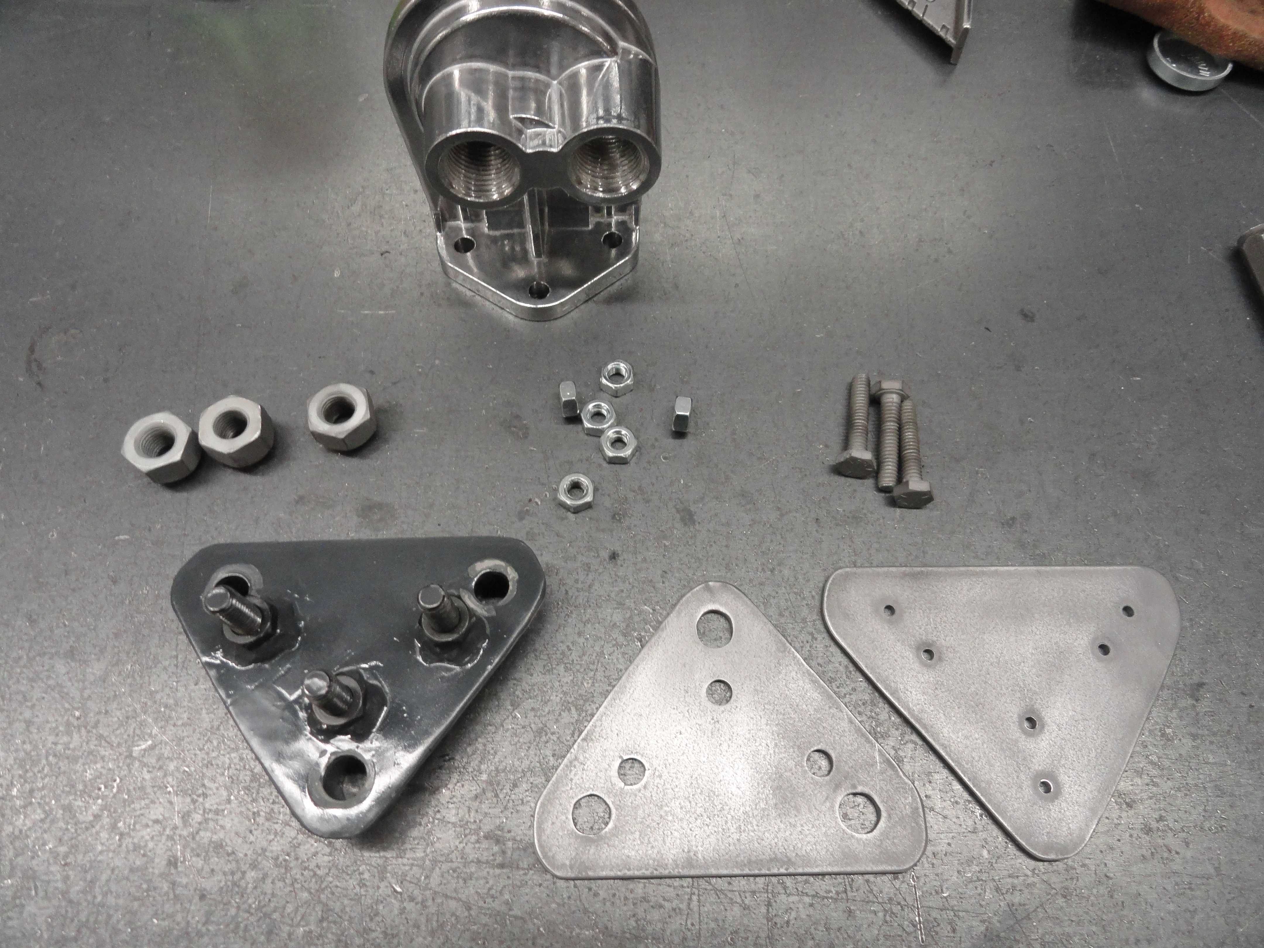
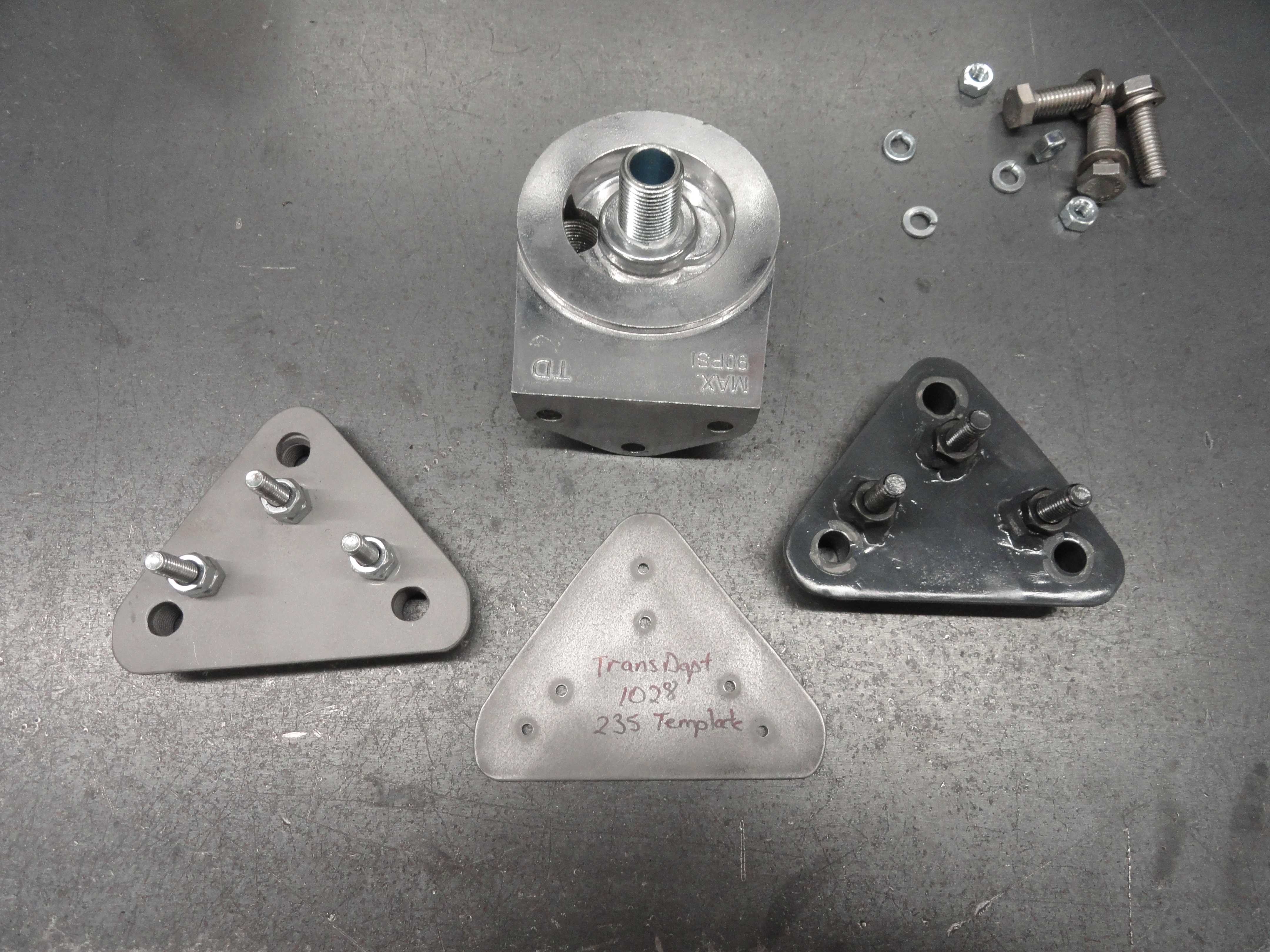
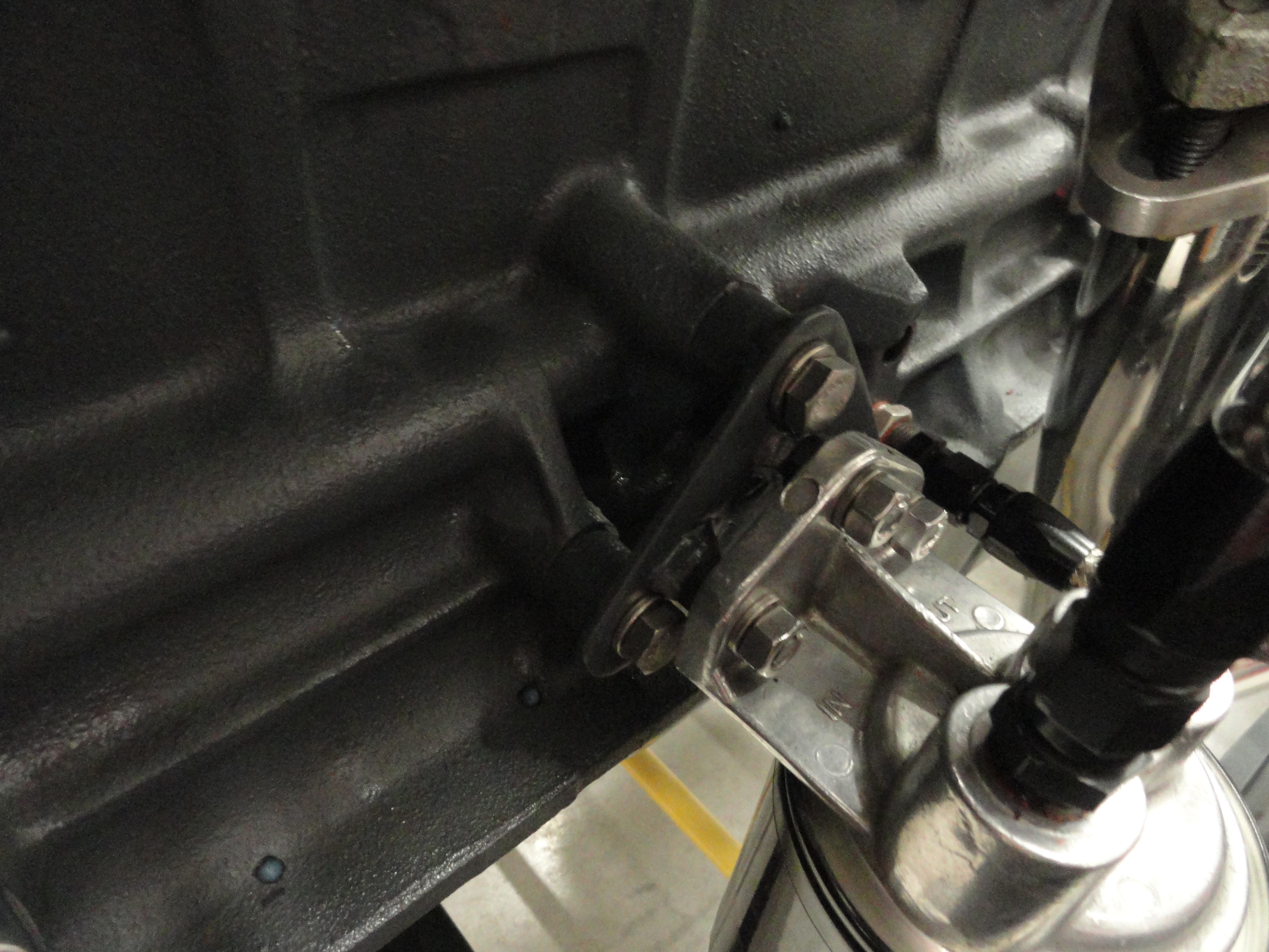
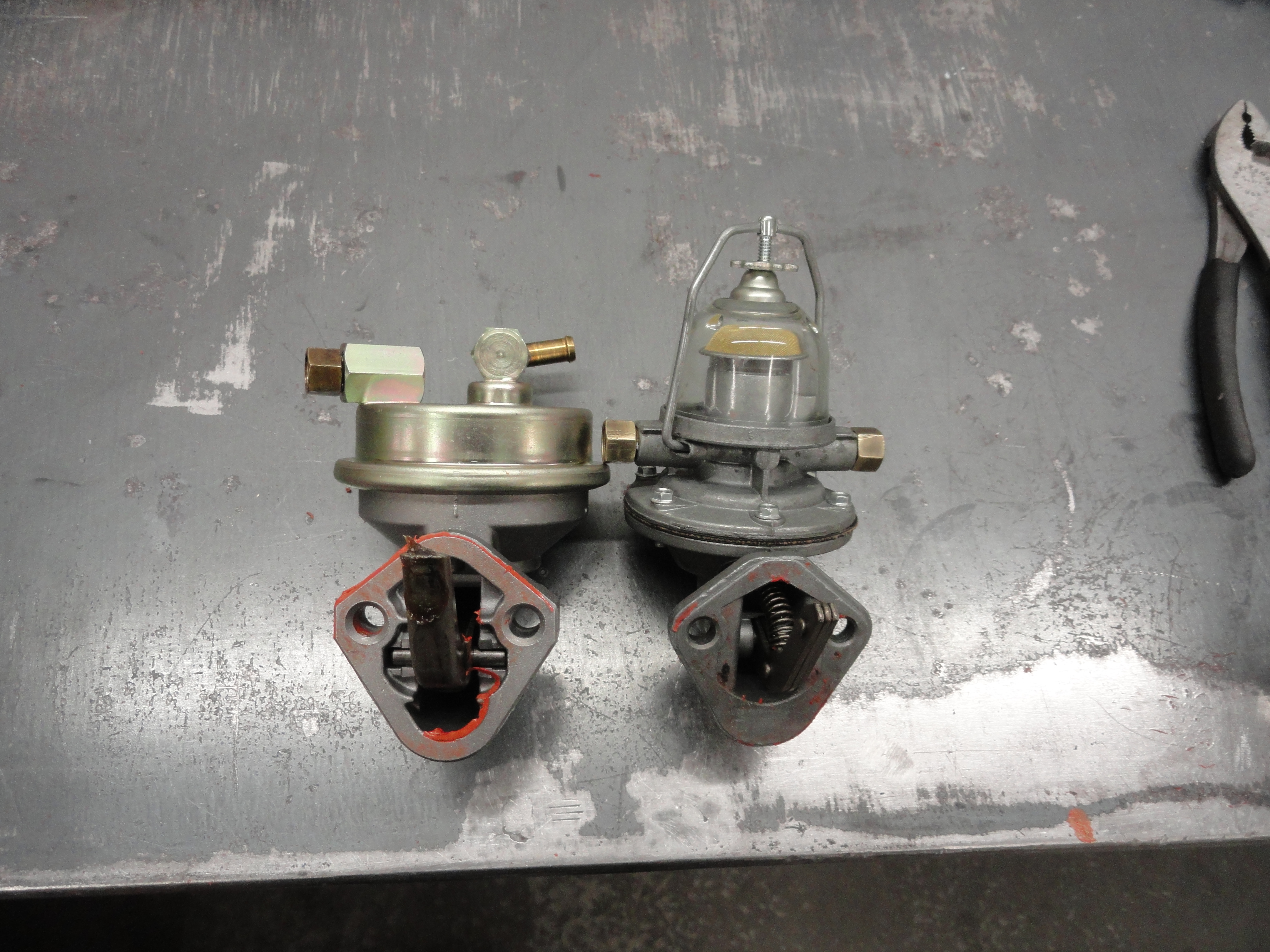
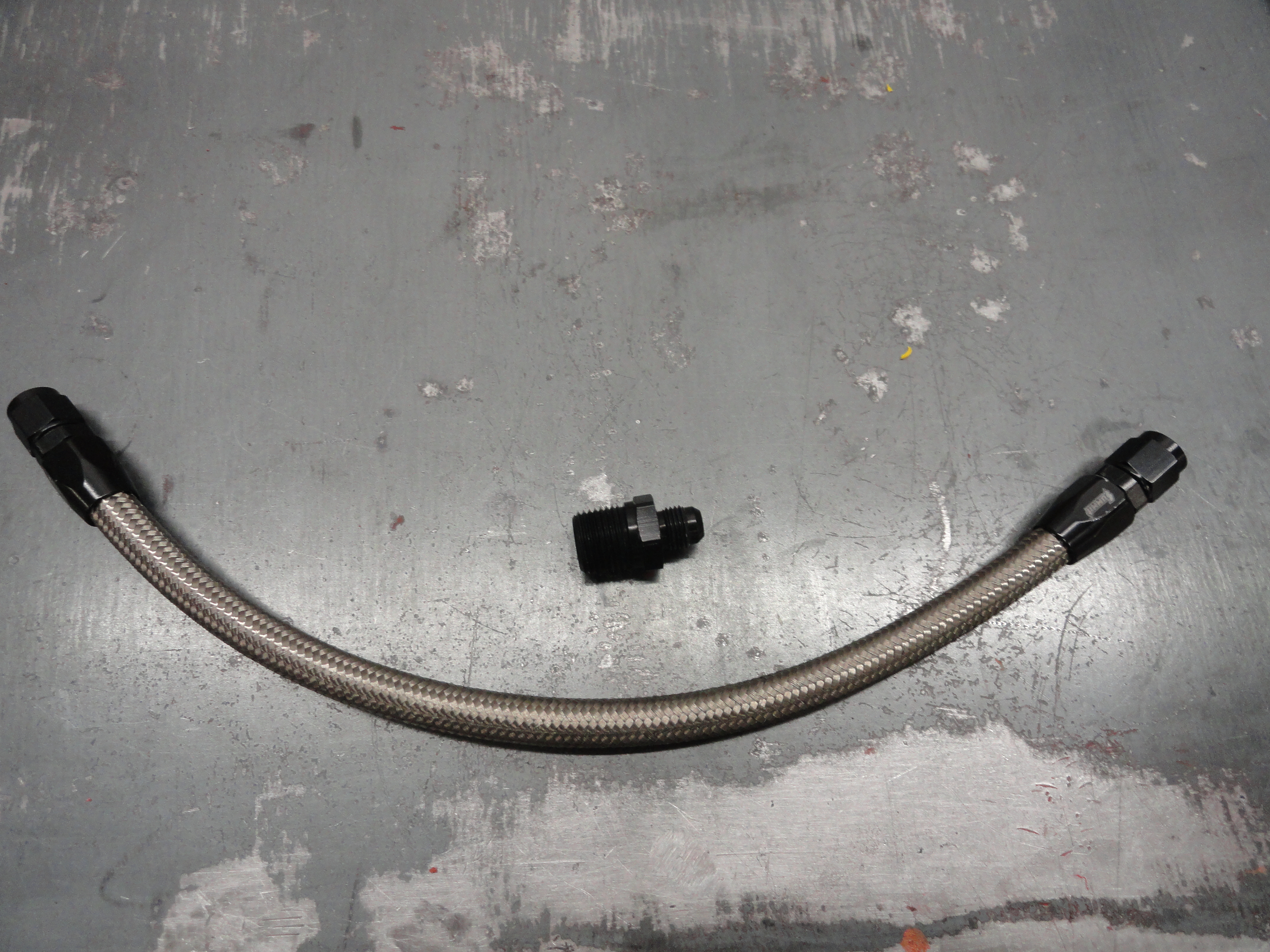
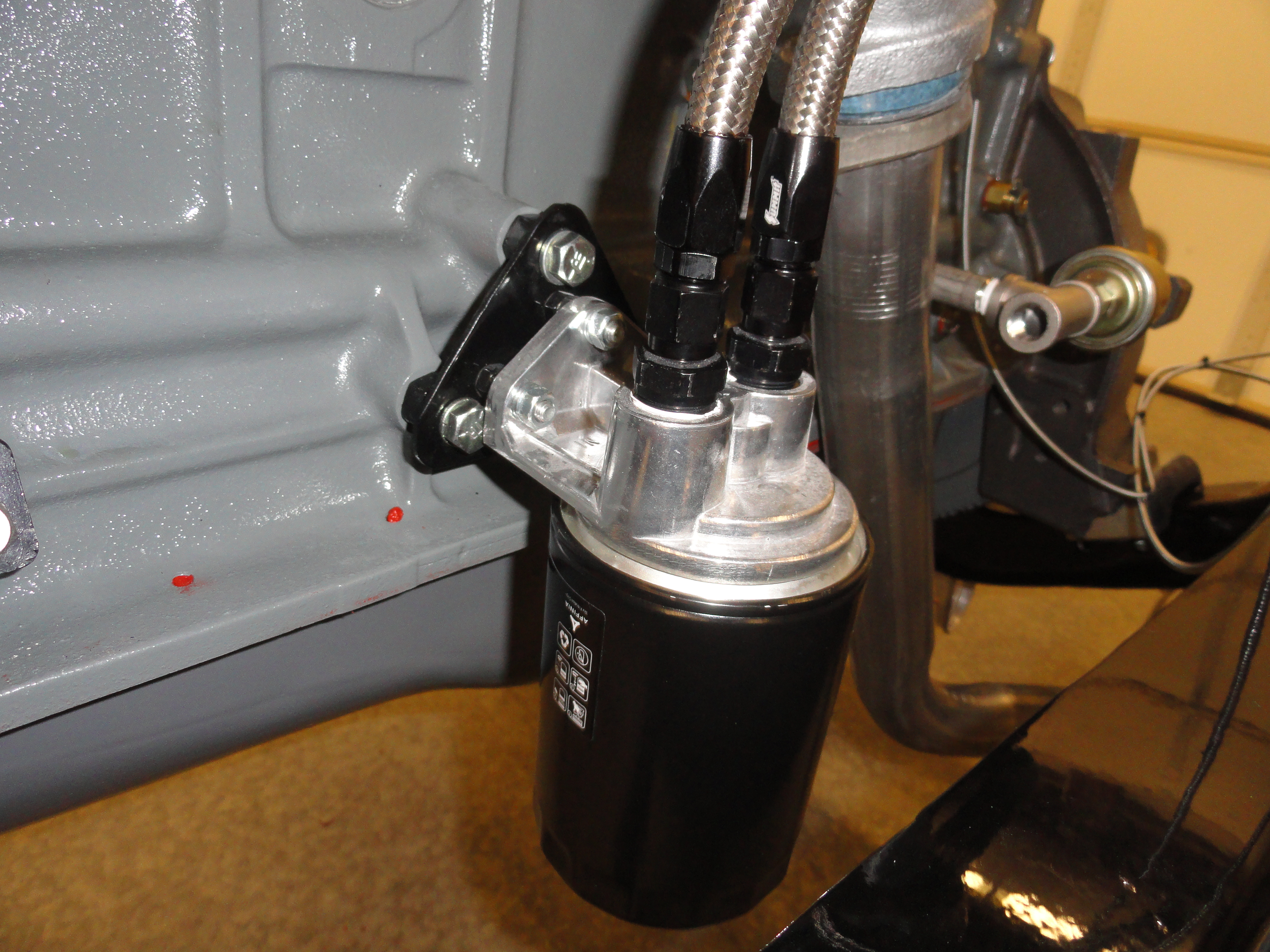
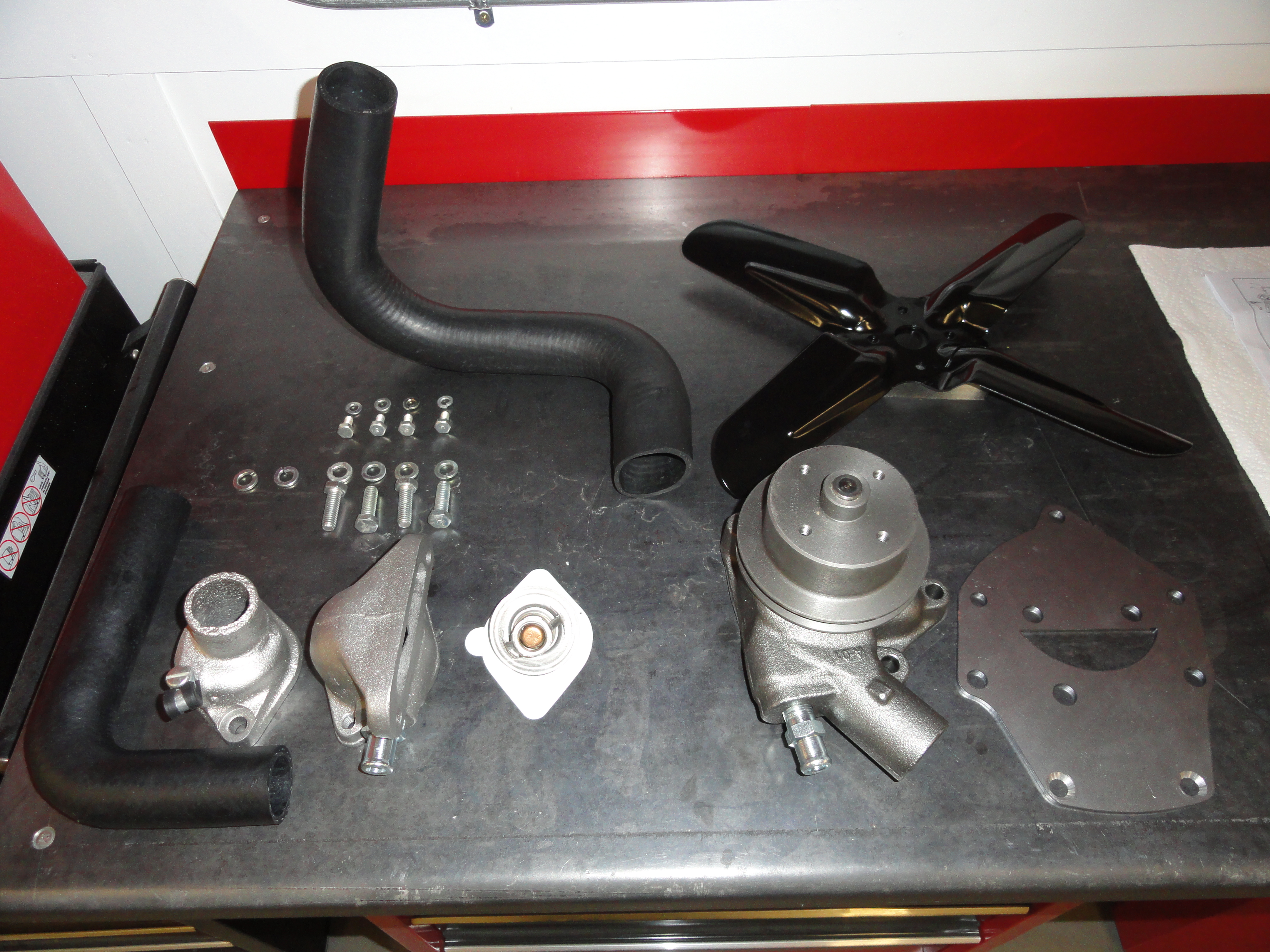
The Intake and Exhaust Manifolds on these old engines can be problematic. They will be thoroughly addressed before re-installation. We will tear down the distributor and carburetor and rebuild them from the ground up. We will install a new one wire alternator, a new starter, fuel pump and water pump. This engine will get the water pump adapter plate with the short shaft water pump to relocate it to the center of the radiator. We will be adding a PCV Valve as well. PCV removes combustion gases and decreases sludge in the oil pan and it's a very inexpensive way to ensure long engine life. We will also be adding a spin-on oil filter adapter kit to go with our new full flow oil system which we paid a little extra at the machine shop to machine for us. There is a nifty place to put this spin on adapter which is at the side motor mount location. We have to make a special adapter for this as well. By the time we are done, this engine will look as good as it runs and because we are very meticulous we expect to get longer life and better performance out of it with our upgrades. (everything above and also HEI).
If you have a 216 or 235 engine with a bypass system, but want the benefit of a spin on oil filter, (still Bypass but easier to change the filter), you can do one of two things. A good choice is to get the WIX Model 27455 Spin On Adapter which mounts to the intake manifold just like the bypass filter did. The WIX 51050 Filter is used with that system. This 51050 Filter has a built in .0625 reduced orifice to keep the proper oil pressure. Really it's a good kit because you just purchase it and it will work just fine. The only disadvantage is it uses a non-standard thread and will not work with other brands or types of filters. Another popular thing to do is purchase a Trans-Dapt 1028 Spin On Adapter which uses an everyday PH8A, FL-1, NAPA1515 spin-on filter and then somewhere in the line add a .0625 restrictor. It's not hard at all. Just tap the inside of one of the fittings for another fitting with a 1/16" hole in it.
Next I will address all of the misc. parts that go on the engine, like thermostat housing, alternator bracket, etc, etc. This brings up something else rather important which is making a list of all the misc. parts that you wish to replace on your nice new fresh engine. I will put that list near the end of the article so you get an idea of the added expense. I opted to go with a 12 volt, One Wire Alternator. I do not like that it doesn't look stock, but trouble free operation and lack of regulator, make it a stronger choice. This choice is necessary because the other improvement will be High Energy Ignition using the 235's Stock Distributor. You can see a very detailed How-To on the HEI system HERE. To do this right, we need a decent Alternator Bracket, and a 12 volt, .700 ohm HEI Coil. We will use the stock looking type. We will also need a few Ignition parts. Reluctor, Reluctor Pickup, Mounting Plate, HEI Module, Heat Sink. The engine did not come with generator or starter so we get to choose the most efficient options for this engine. This allows us to customize our engine the way we want.
This is the list of parts that need to be purchased to complete this engine to my satisfaction. This will be incomplete for you because I am only replacing the items I ran across during this build. Also Part numbers are forthcoming...
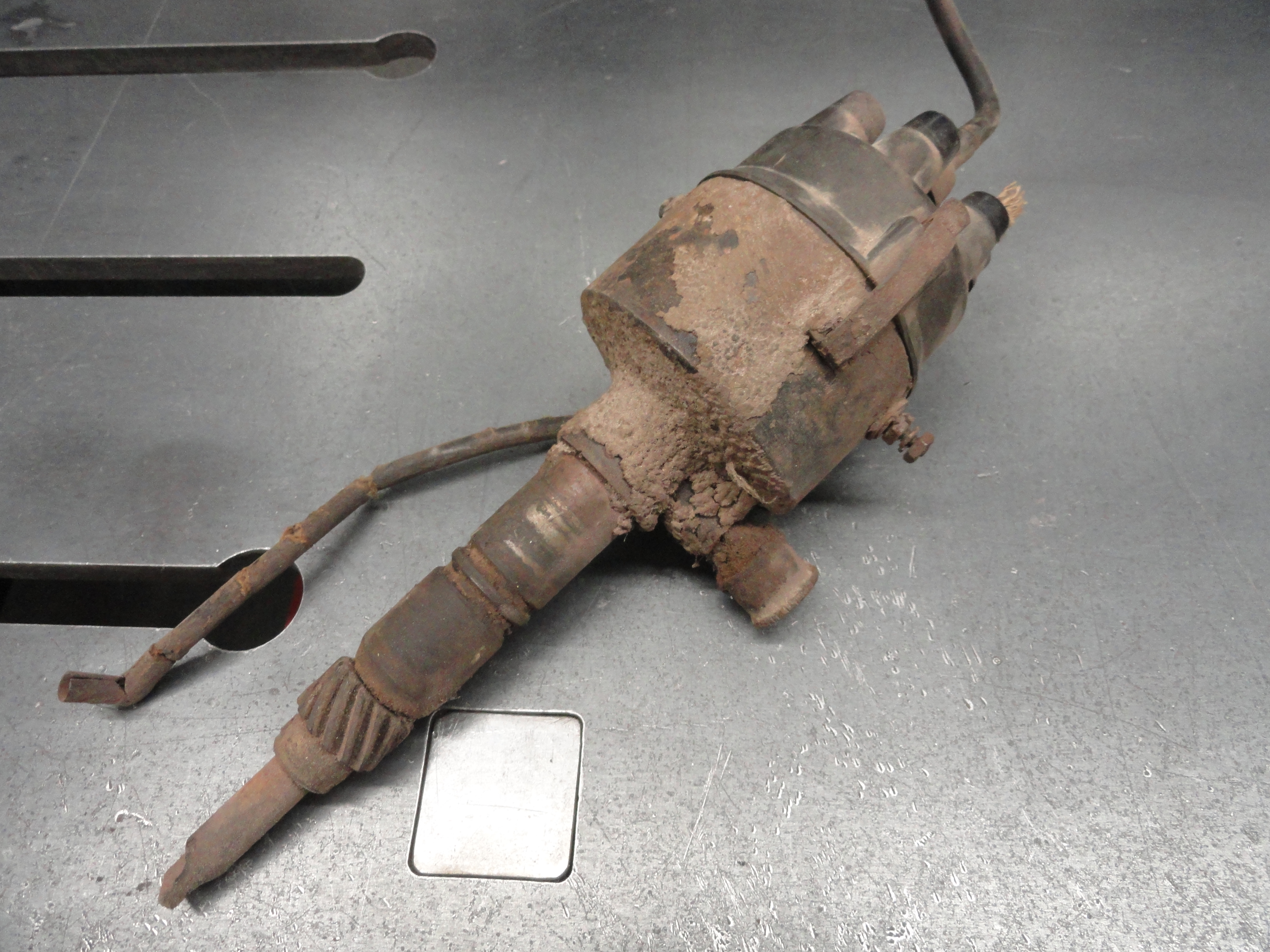
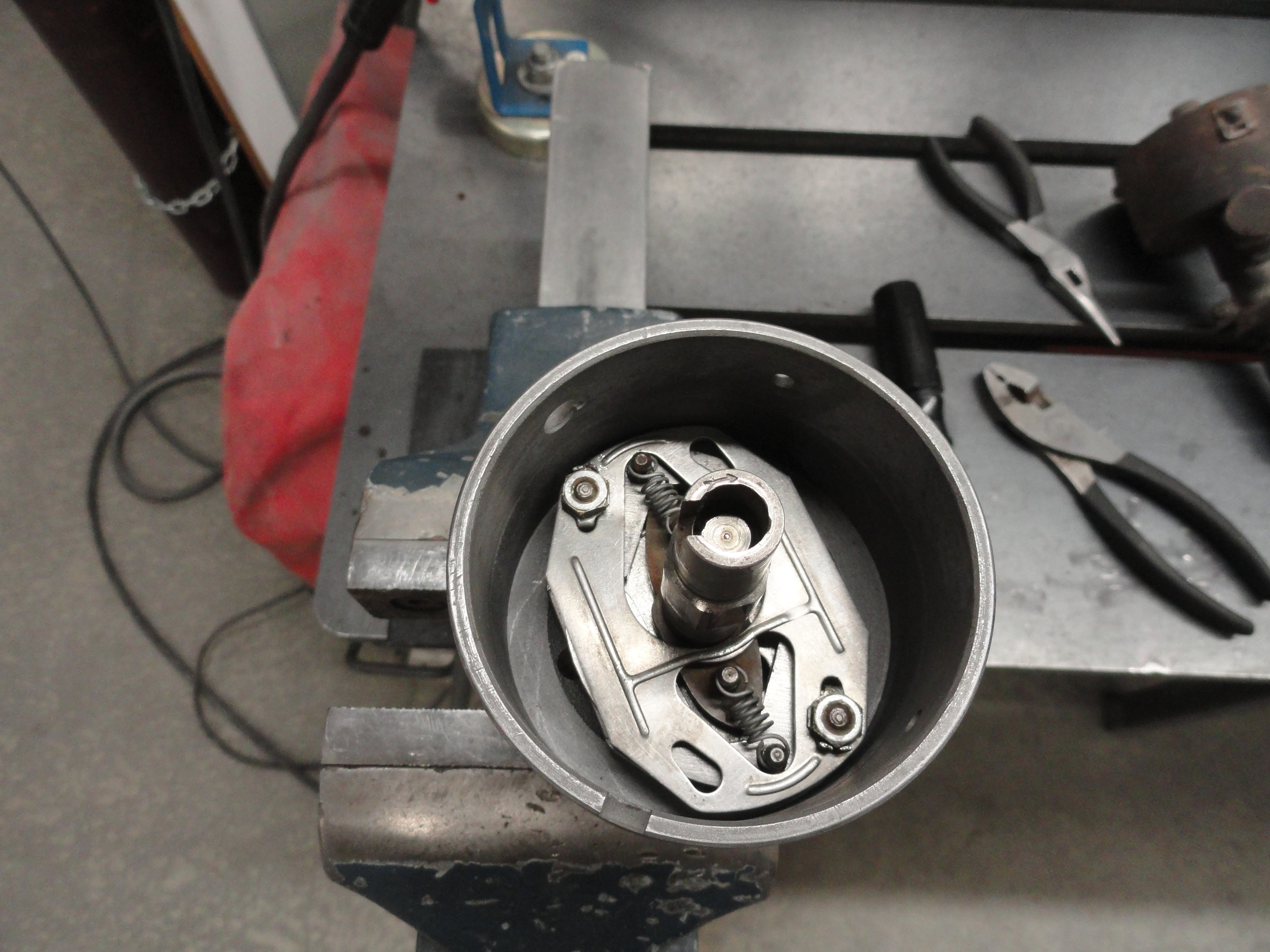
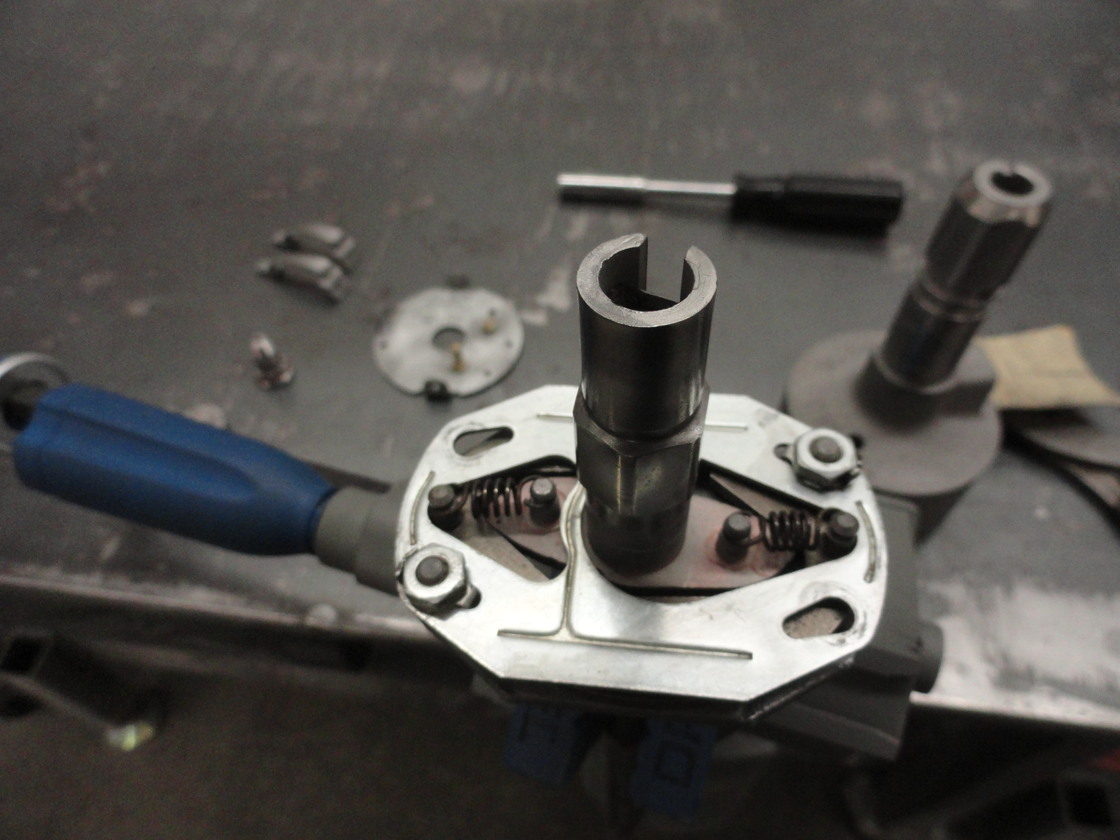
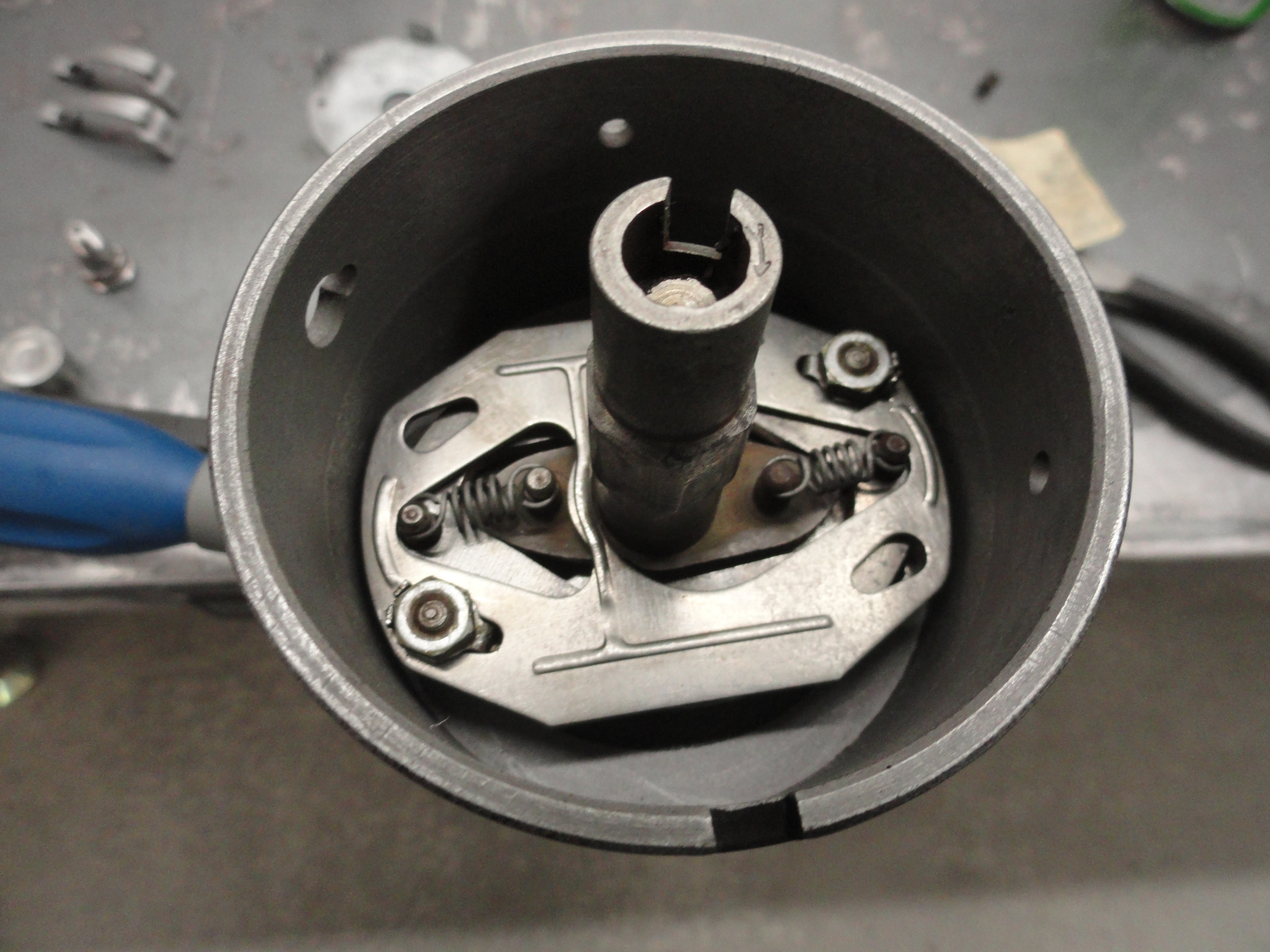
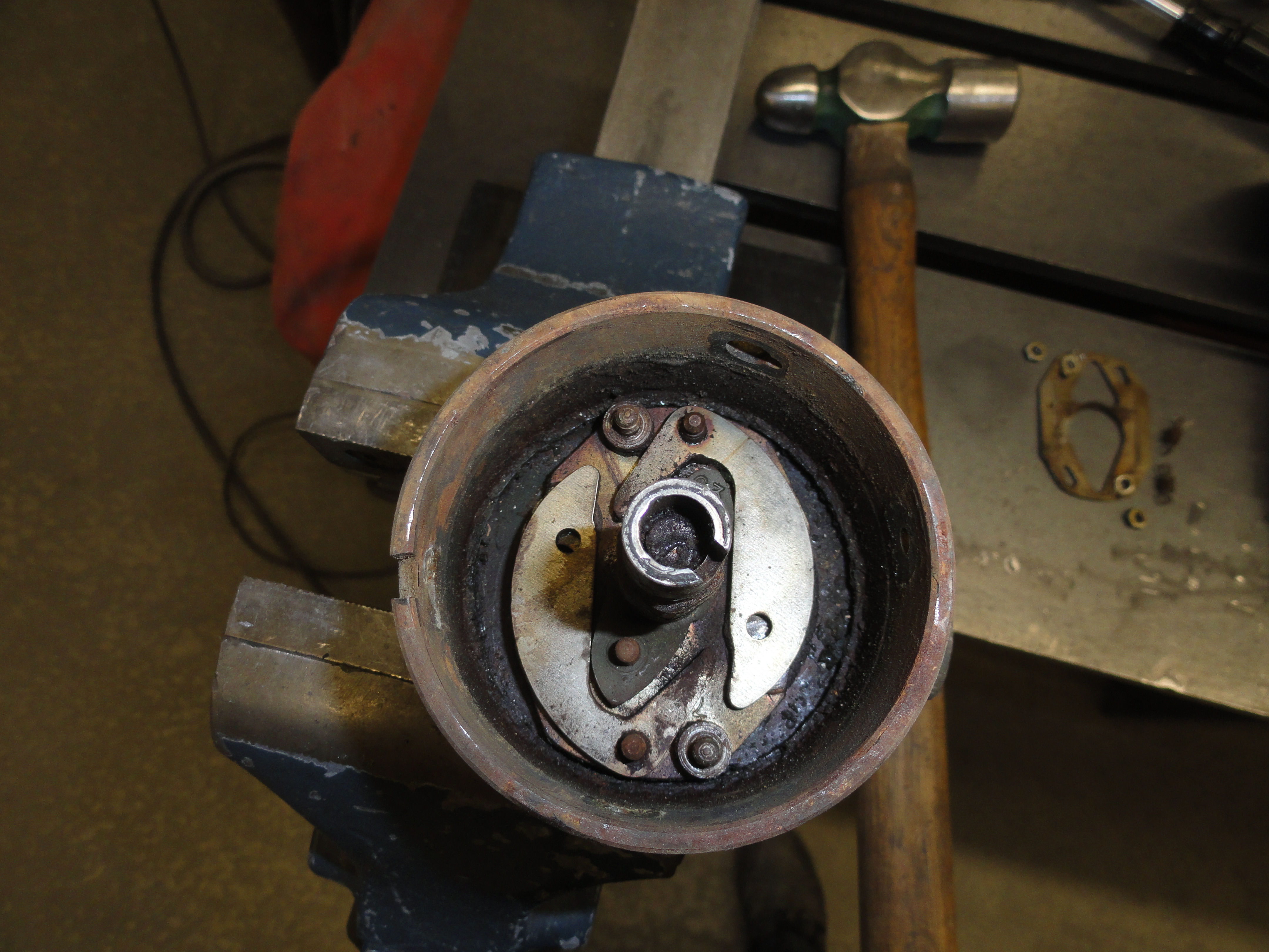
I decided to just go ahead and rebuild 5 of them since I had them laying around the shop and eventually will need them anyway. This gave me a complete understanding of how things go back together. First order of business after removing the Distributor Cap is to remove the points and condenser. Go easy on the phenolic (black plastic) pieces because they are getting very hard to find. If the condenser wire pulls right out, great, but if its stuck in there, first remove the nut on the outside and the conductor plate. This will reveal a round nut with slots on both sides of the screw. With something small, just rotate it out a little and your condenser and points will come right out. Let's go ahead and remove the plastic pieces. This by again, removing the nut and conductor plate, the round nut and then behind the round nut goes a lock washer. Once you have all that removed, take the screw out (carefully) and the two plastic pieces should just pull apart from each other and come out as well. The plastic pieces are very nuanced and seem to be the most difficult pieces to find along with that round nut and special screw. Don't lose anything!
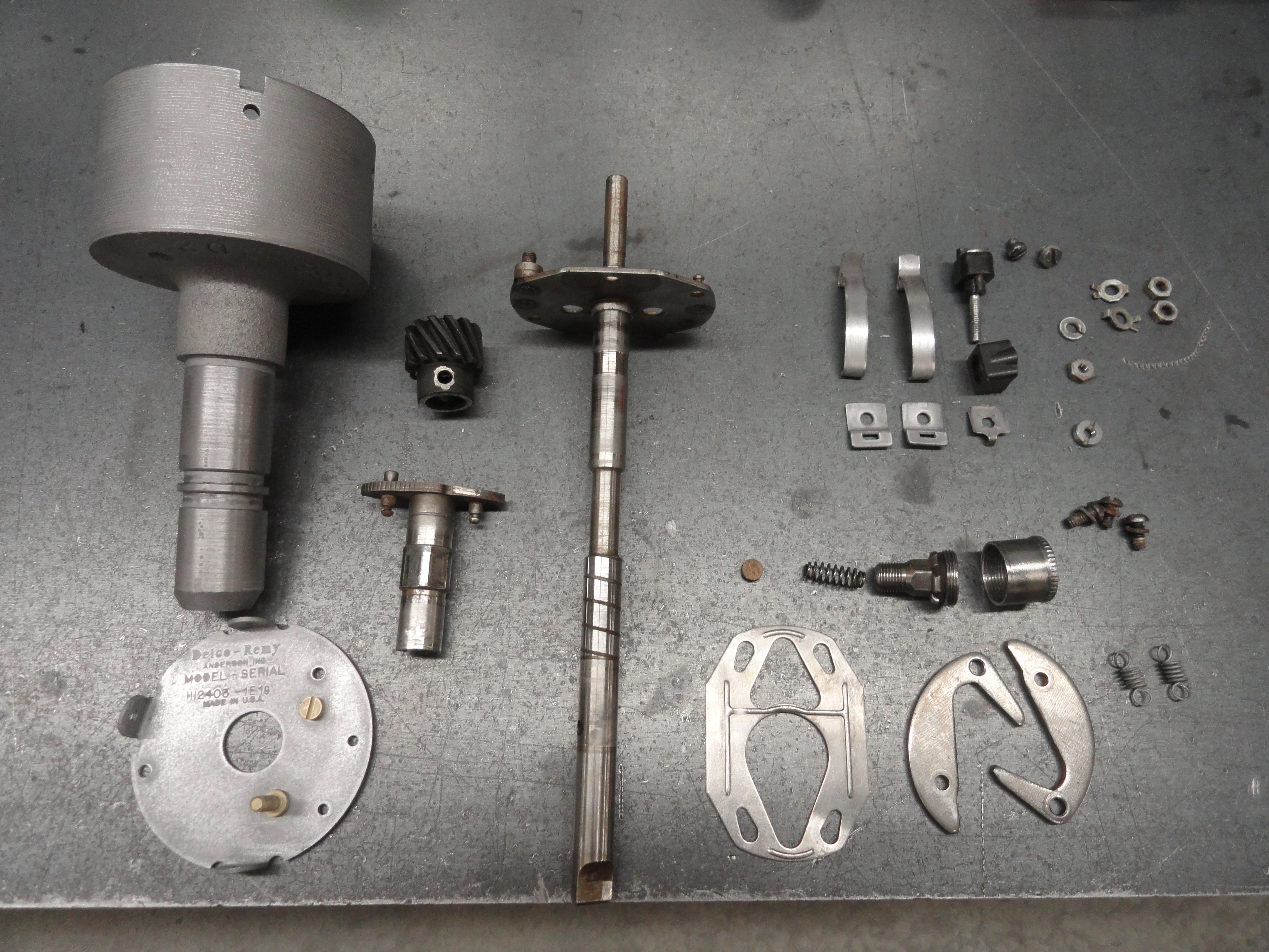
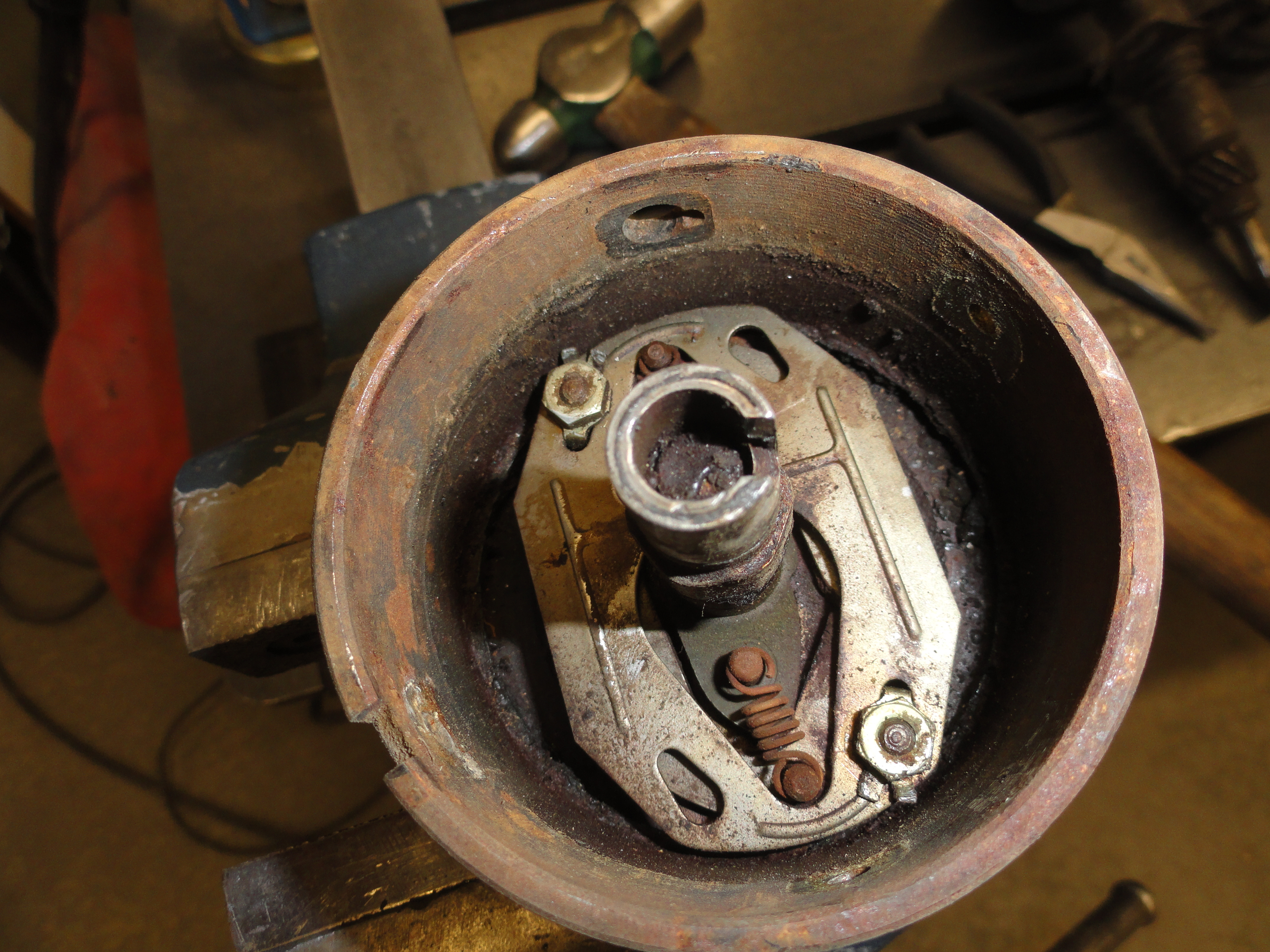
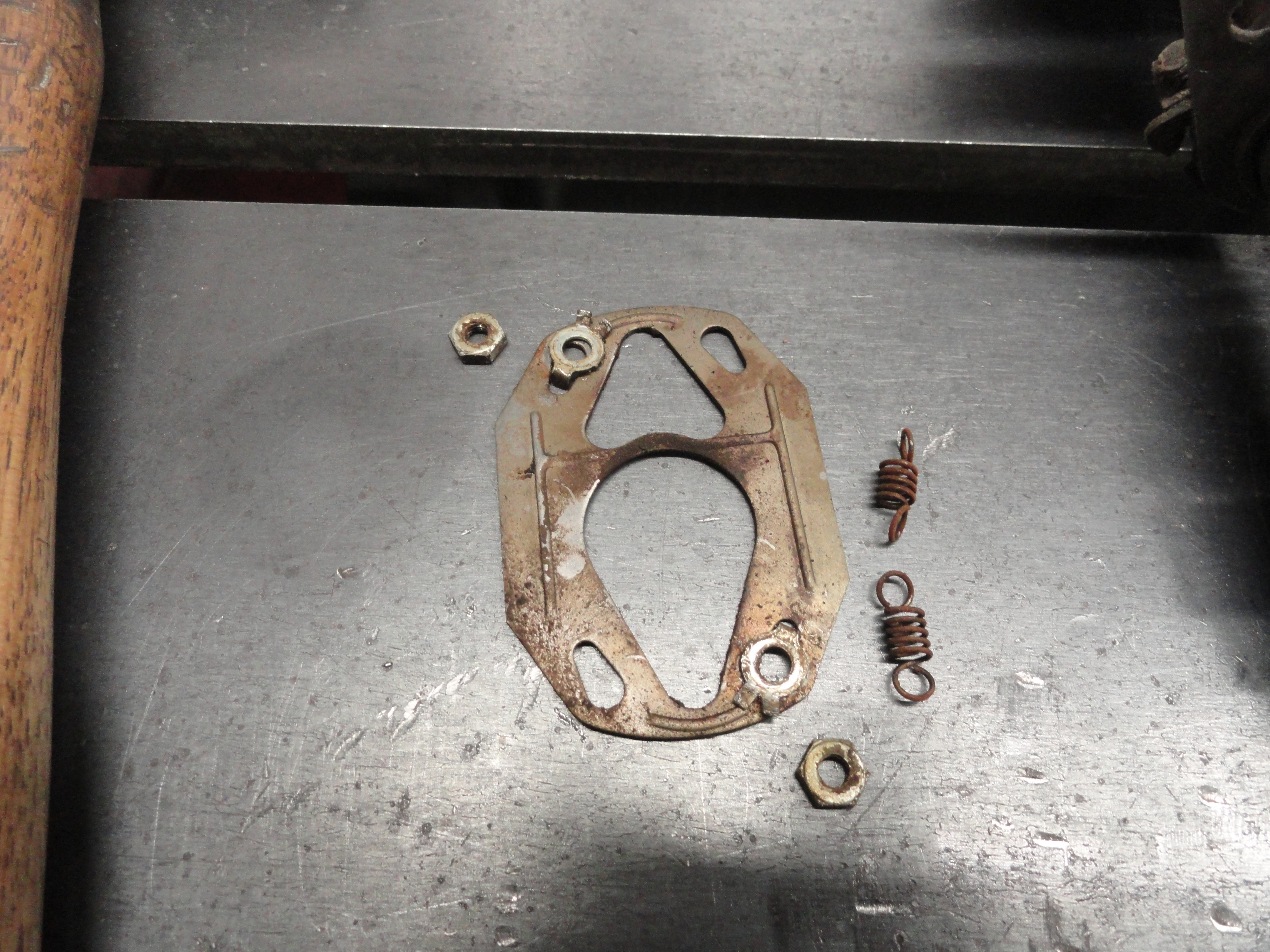
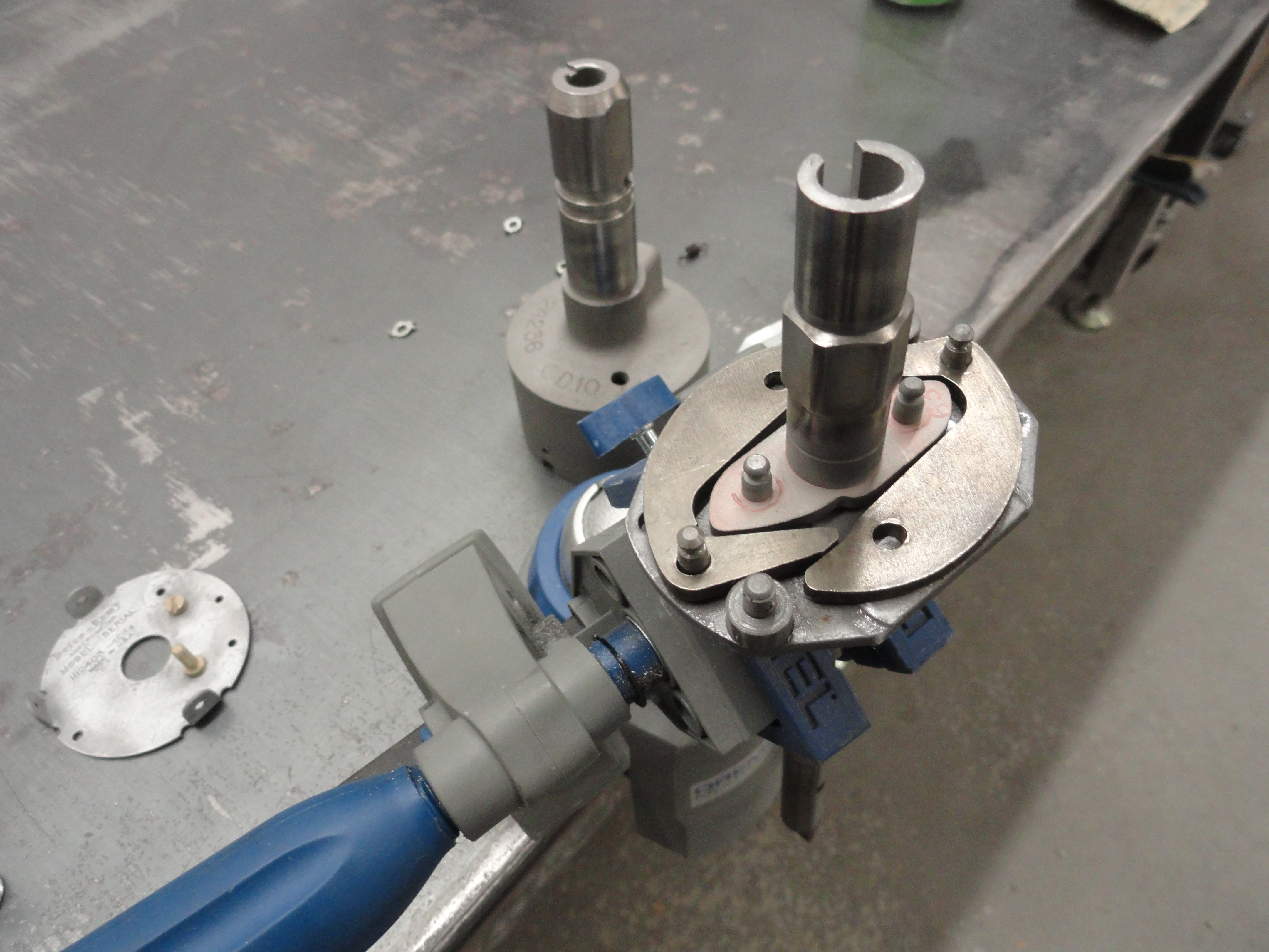
Now remove the top plate assembly by removing the three screws on the outside. Two of these that are across from each other hold the Distributor Cap clips. These screws are the same and each has a lockwasher. Once the top plate is off we can see what's next. Take a close look at what you have. No need to take pictures if you are reading this, it's been done for you. Notice how the plate is oriented. We will want to put it exactly the same way when we rebuild it. There are two nuts holding the assembly together. The nuts have lock tabs and that's pretty important since once its together, they are hard to get to. Carefully bend those two tabs out far enough to remove the nuts. Place all of your parts on a nice surface where you can see what goes with what. Once you have the two lock tabs out, pull the plate straight up and out. Notice how the indentions face upward. We want to put it together the same way. Now remove the springs. Don't lose them. I was actually able to just reach in there and pull them out by hand. Not much tension on them at all. Now remove the mini shaft that has your lobes on it, then the two counter weights. That should be everything on the inside.
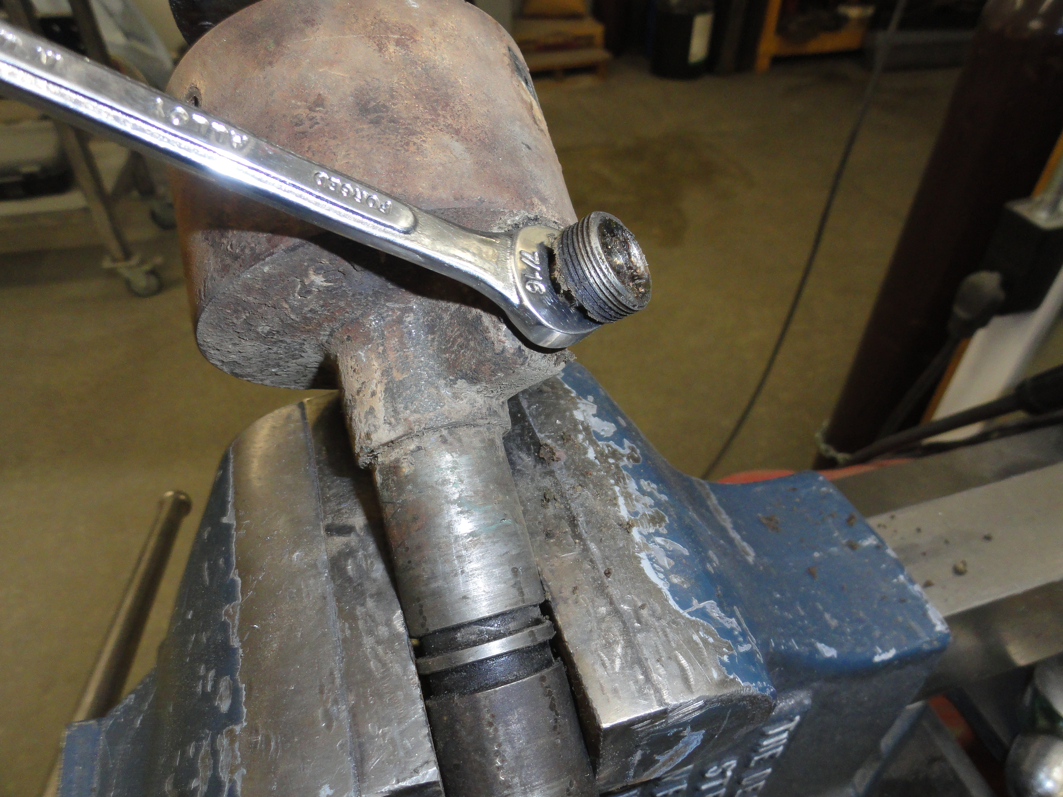
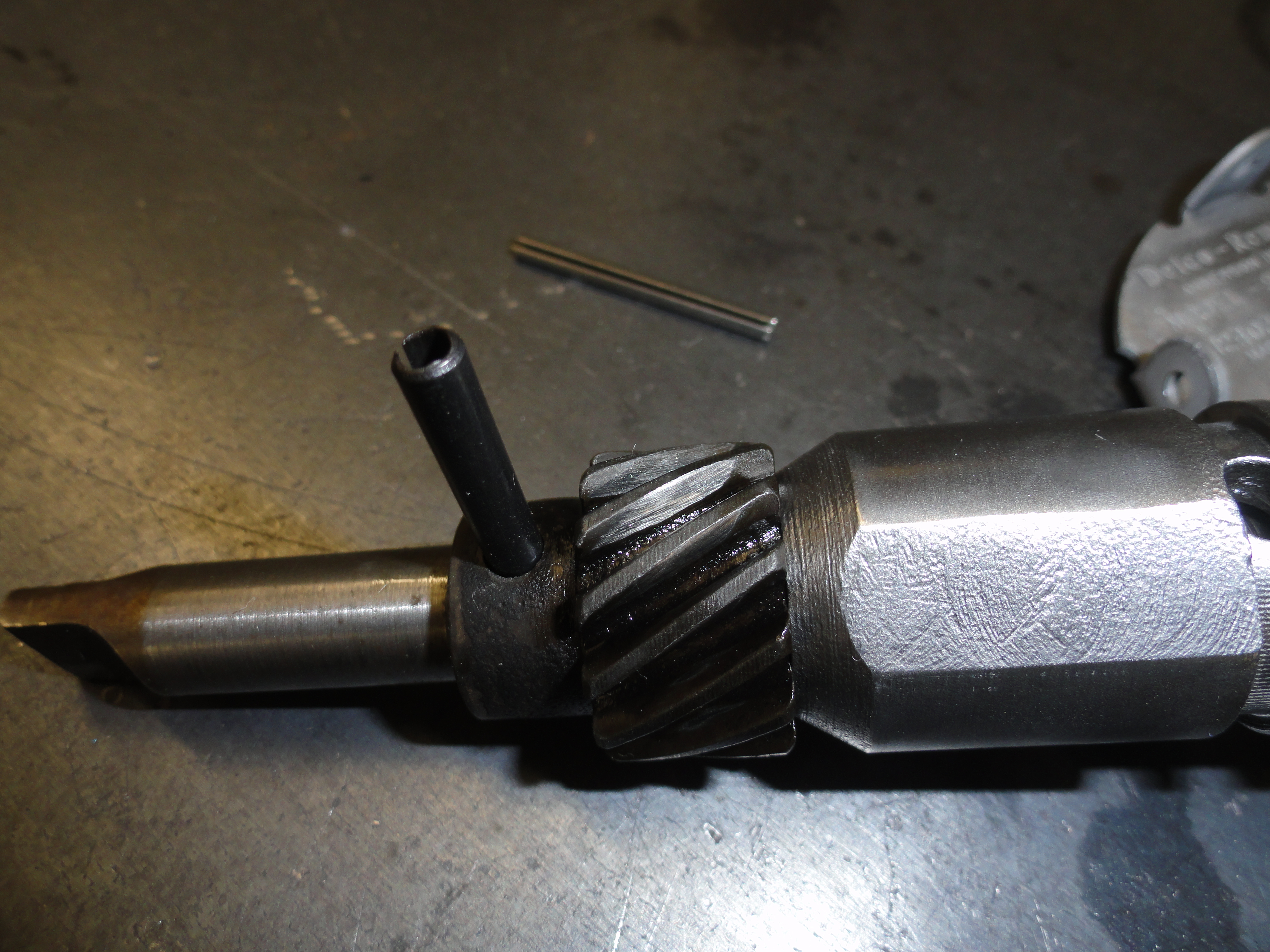
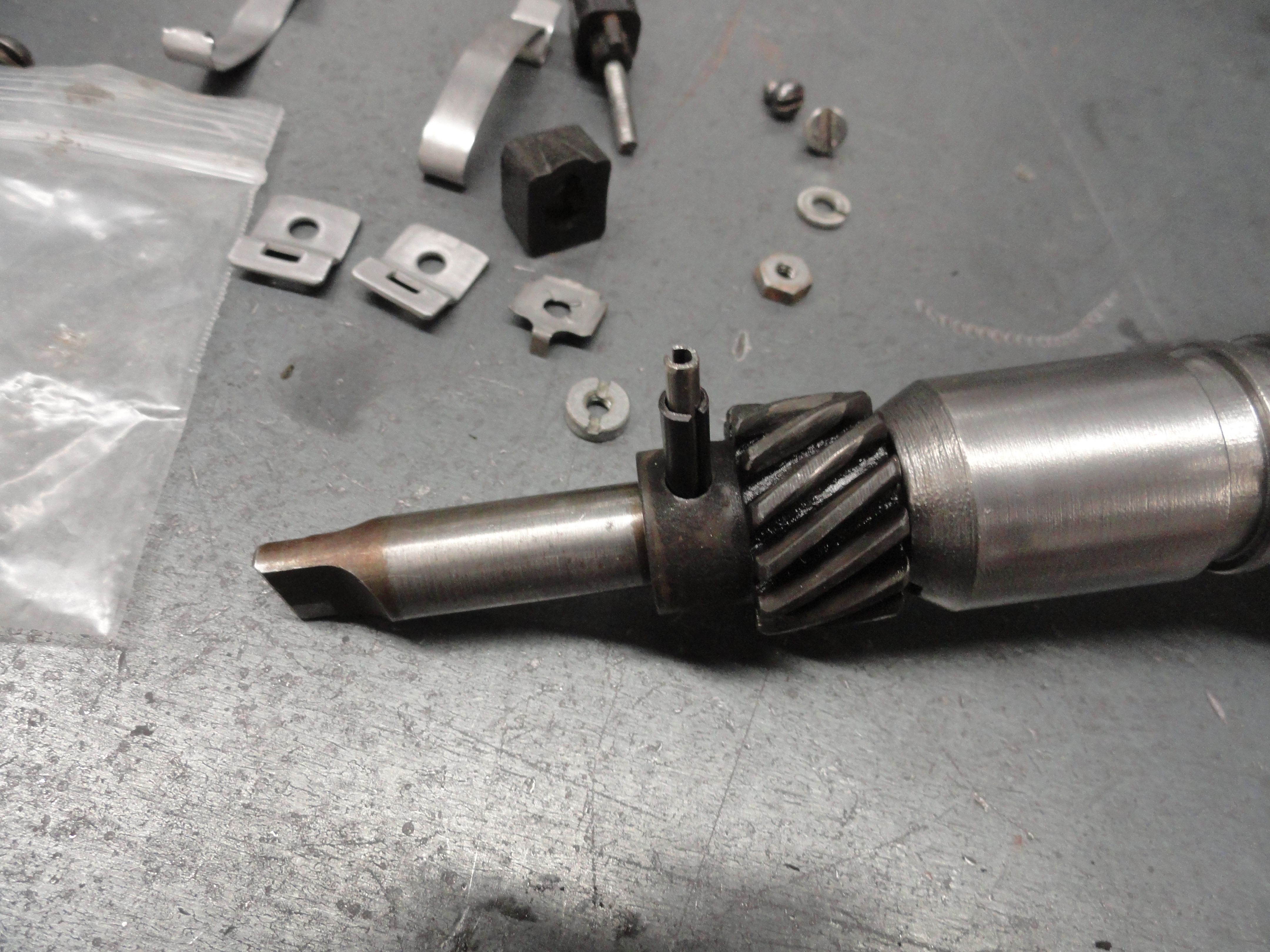
On the outside, let's remove the grease cap, then with a 7/16" wrench, the threaded grease assembly. After that is out, there are two more parts in there. One is a spring and the other is a plastic bushing that pushes against the shaft. To make that bushing retrieval just a little easier, I went ahead and removed the drive gear. Be very gentle grinding off just the head of the pin thats holding it in. Use the appropriate size punch to knock the pin out after grinding. I have never had one in there so tight that it was impossible to remove, just be sure your punch is small enough for the hole and it should come out with moderate effort. Once the pin is out, work it around a little and the gear should slide right off. Now you can remove the inner shaft assembly. That's when I was able to take the punch and push that little plastic bushing out into the center of the shaft housing, then push it out with the shaft. That plastic bushing is important and if its worn out, you can usually find a plastic bushing at your local hardware store that will work just fine. You do not want that spring to push against the shaft without a bushing. At this point you should have everything apart as in the picture on the above left only not quite that pretty.
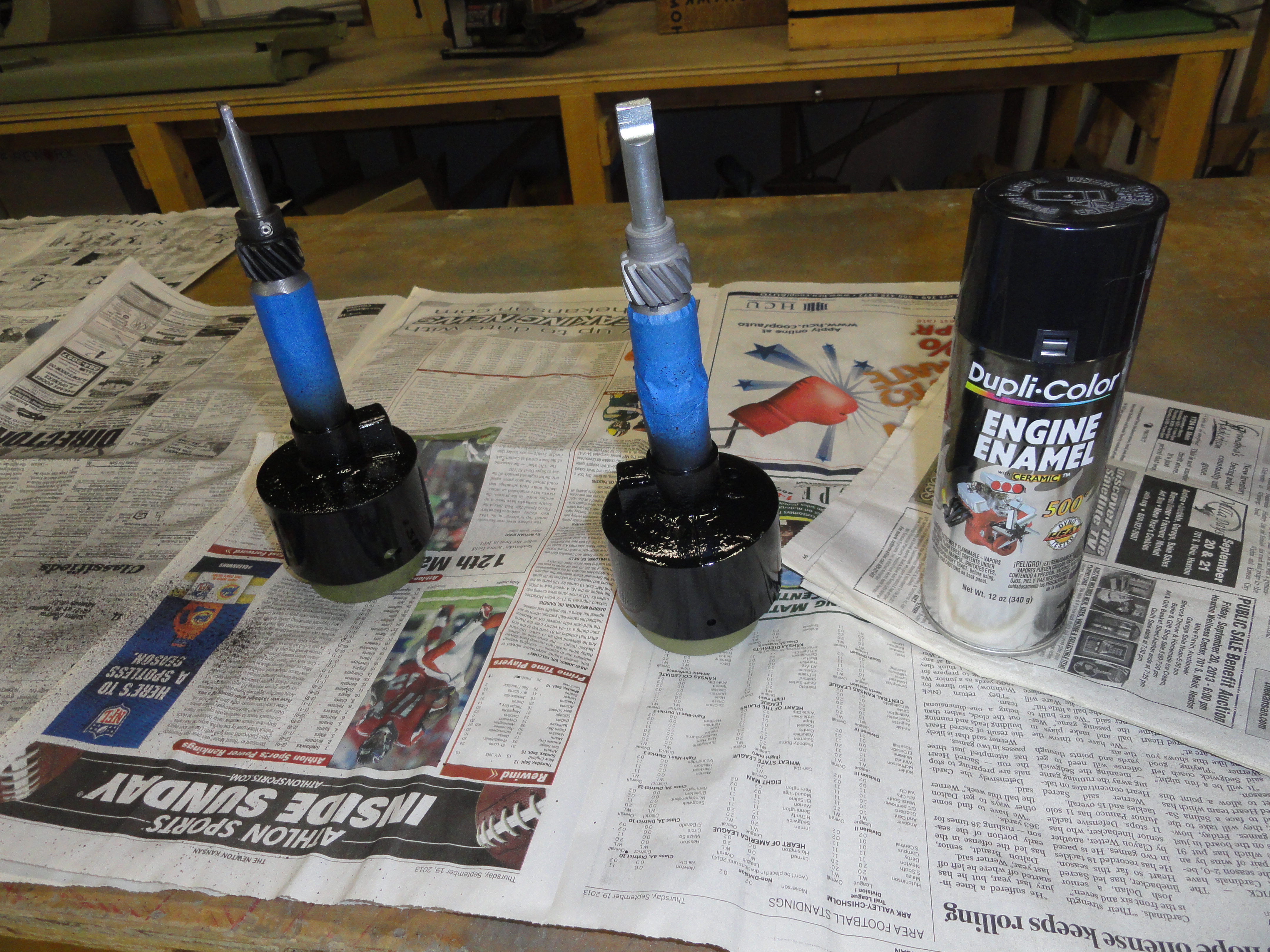
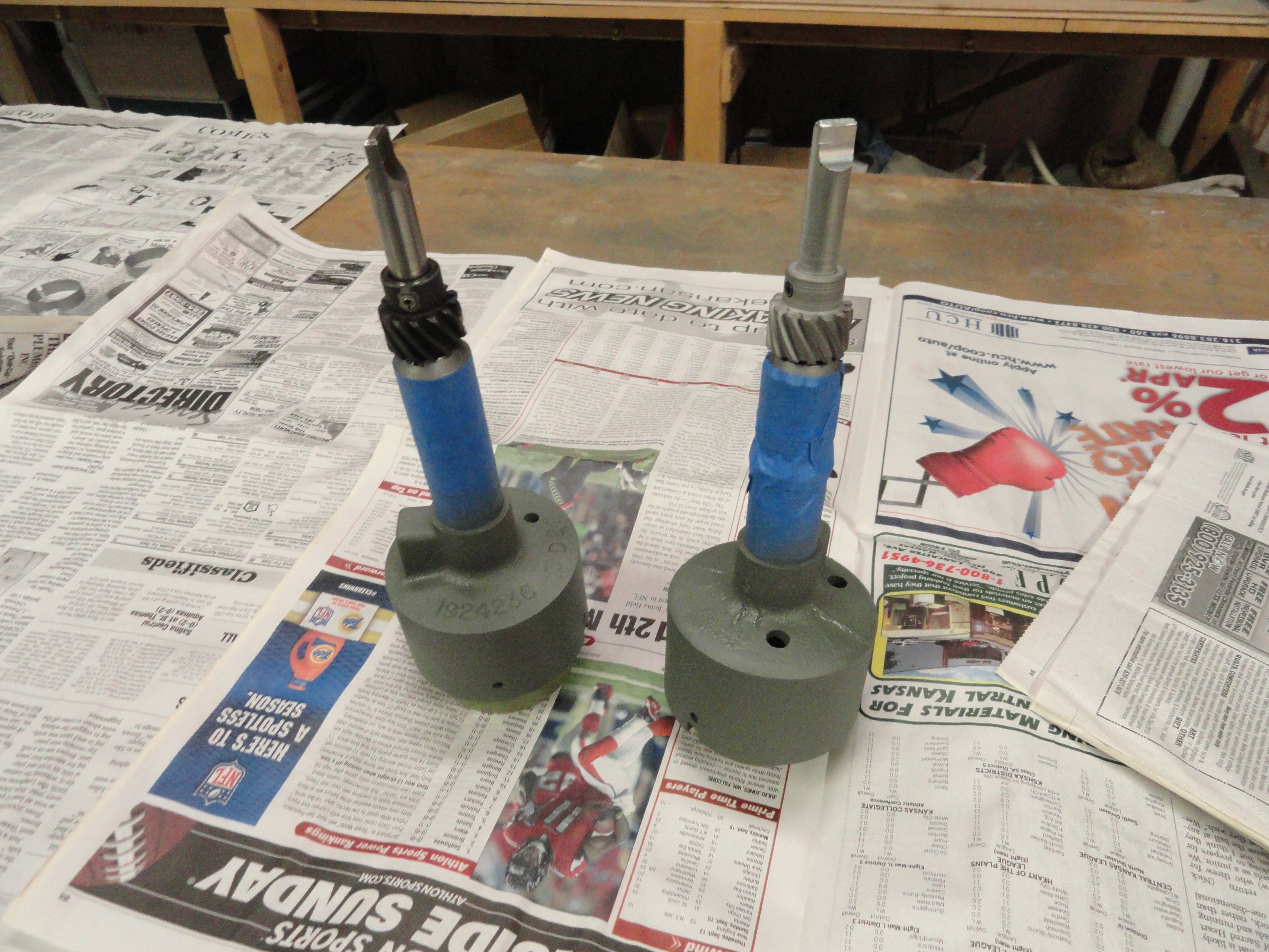
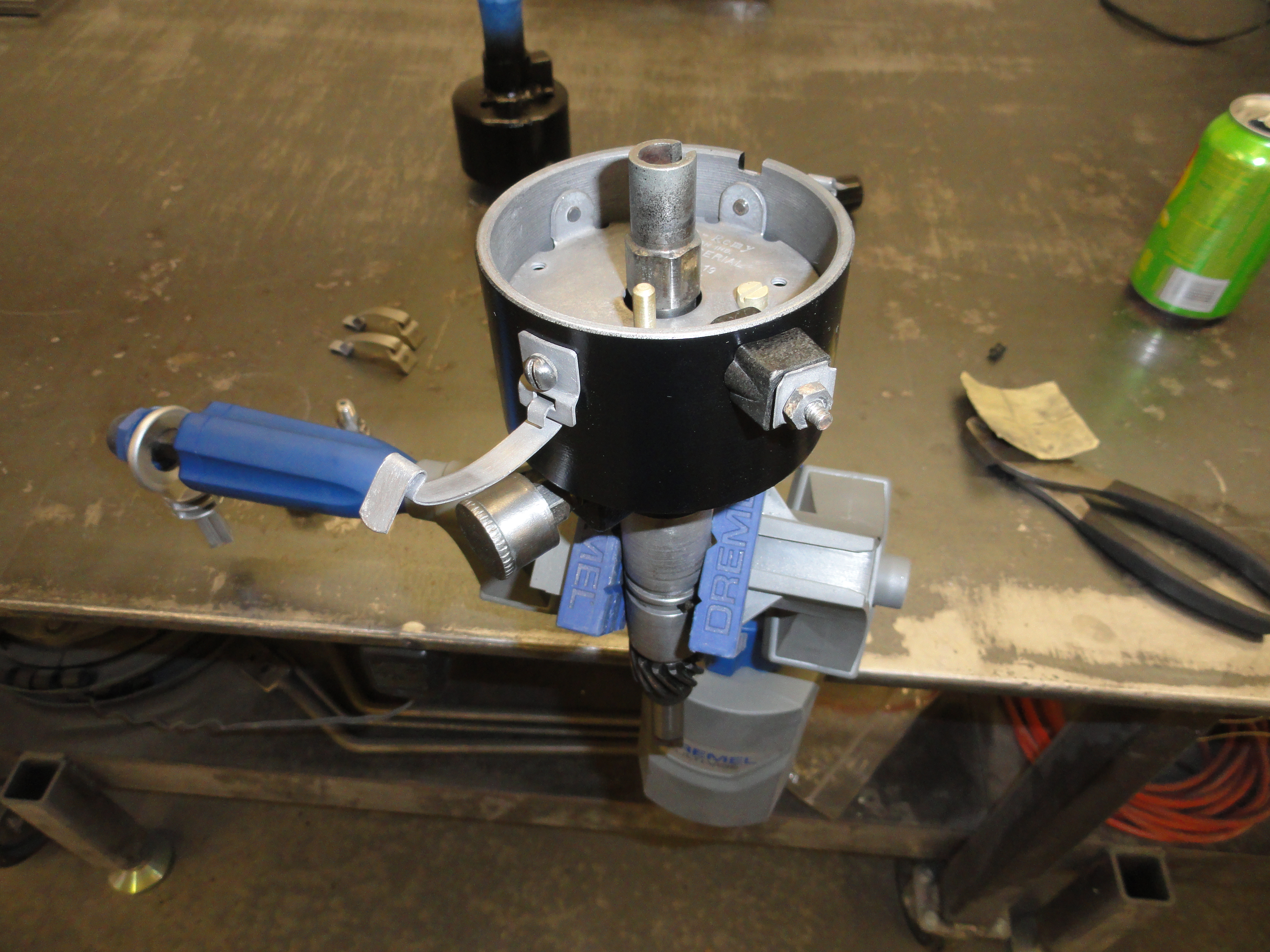
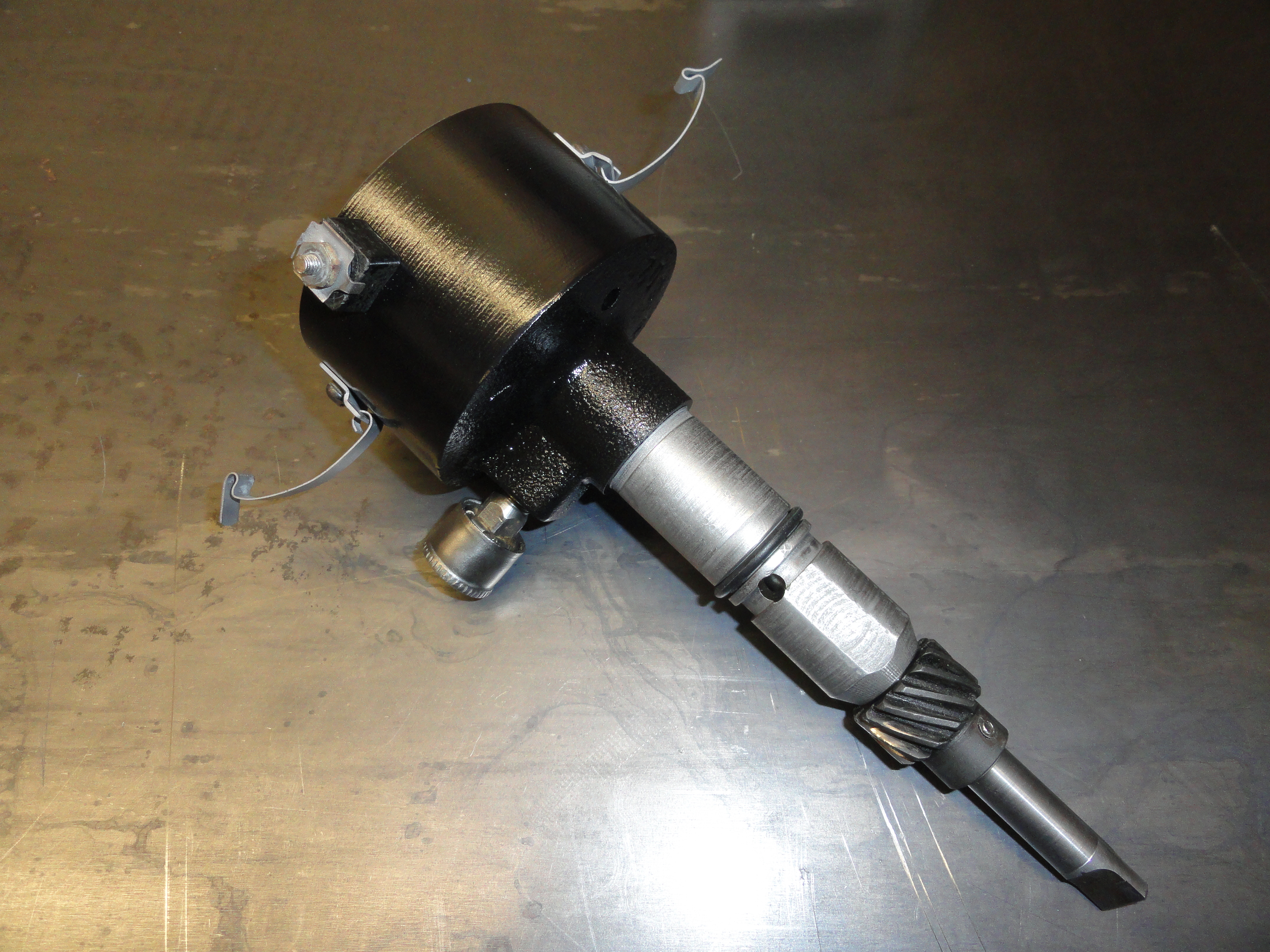
Cleaning all of this was accomplished with the 3 gallon parts washer with Kerosene. Use wire brushes and really take your time getting these parts all nice and shiny again. The machined surface of the housing was taped and then sandblasted to remove all traces of crud. The top plate was shined up with 400 grit sandpaper. Once everything is clean and compressed air is used to blow everything off good, Paint the housing the color of your choice. Flat black was used originally. I painted only the outside and with the tape still on the machined shaft. I used Etching Primer to start. Once the paint is cured, overnight preferably, spray WD40 on all the parts and inside the housing. Place the shaft in the housing and move it up and down to ensure you don't have any more crud in the housing. With the WD40 on it, it should spin very nice and freely. I use the WD40 as a rinse to get rid of any contamination as the last cleaning step.

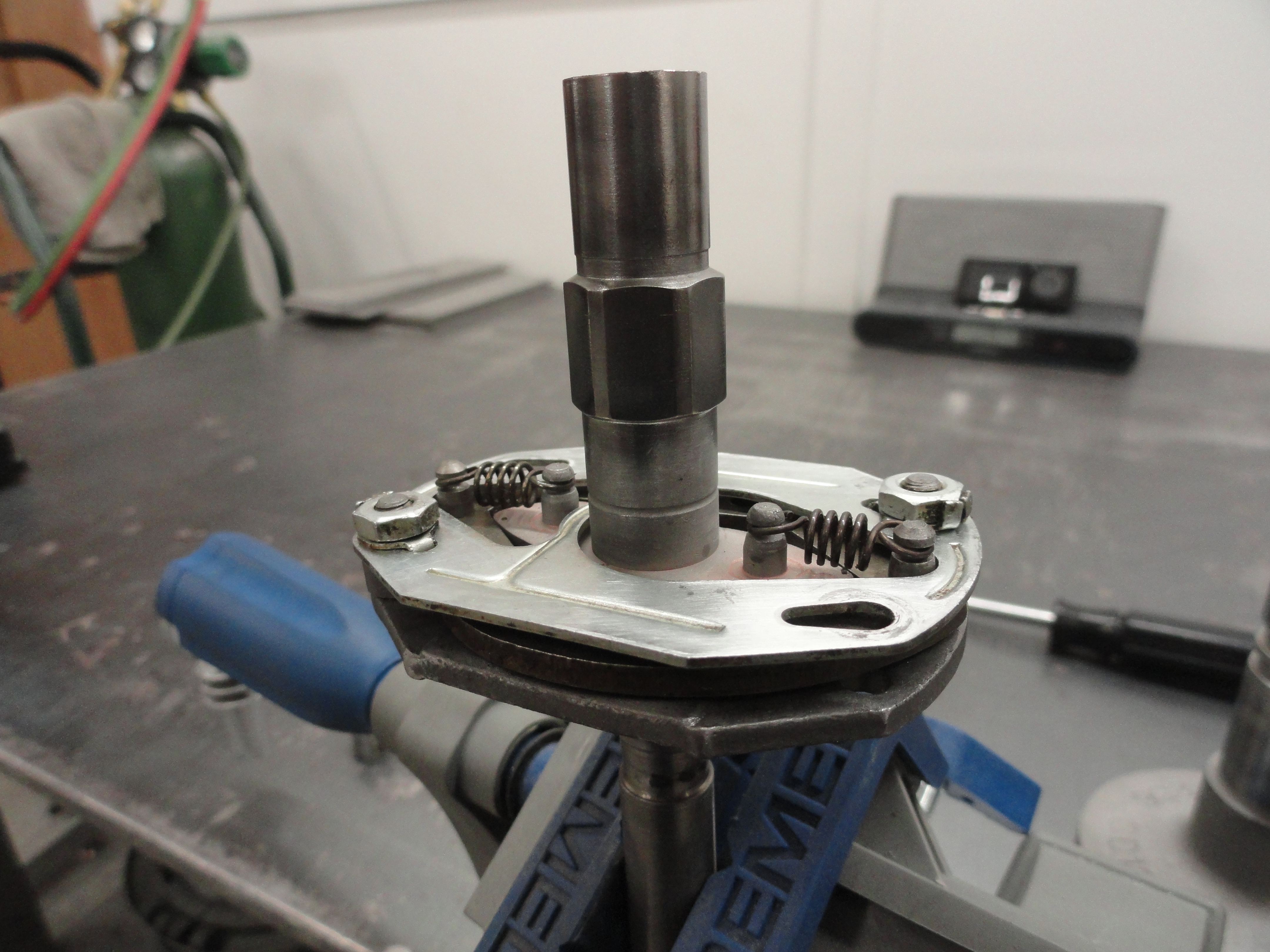
To Start Re-Assembly, put the inner shaft assembly in a vice with plastic jaws, or protect it somehow, and we will reinstall all of the bottom part of the inside. We can do this because the gear will go on last. I use white lithium grease as sort of an assembly lube. I slather it over every part. The Distributor doesn't get any oil and very little grease, so you want those weights to be slick and free from rust in the future. Place the counter weights on first as shown. Once the counter weights are on and they move freely, place the upper shaft assembly in so that it occupies the same plane as the weights. Then install the plate with the locking tabs and nuts. Tighten securely and then bend the tabs over to lock the nuts in place.
To reinstall the gear, get the proper length and size of roll pin. I use high strength stainless steel ones from McMaster-Carr. The 3/16" pin will be tight in the shaft, but I do not rely on that single roll pin. Put another M2.5 (x30) pin inside the first one making sure the openings are opposite each other. This almost guarantees that gear isn't going anywhere. Test it to make sure there is no slop introduced by the pin combination and then cut off the pins flush same as the one that was there in the first place. If by some chance there is any slop in the gear to shaft connection, drill both the gear and the shaft out to the next size roll pin combination which is 7/32" and 1/8". I used a 3/4 horse Bench Grinder with wire wheel to brush off alot of these parts after cleaning in the Kerosene. Whatever works as long as things are clean.
Reinstall all of the remaining parts as they were. The top plate is attached by the 3 screws/lockwashers and the two across from each
other also get a clip retainer. The slot in the retainer goes down and the retainer follows the curve of the Distributor housing. The
black plastic pieces go on as shown. Put the screw in the inside piece first, feed it through the hole, then on the outside, a lock
washer goes on first, then the round nut, then the conductor plate, then the regular nut. You can put your points and condenser in
anytime. I chose to leave them out since the plan is for adding a round plate inside to accommodate HEI. Once it's all back together,
that completes the rebuild. We will test this when we get the engine back from the machine shop. There is a very complete How-To on the
HEI setup we are going to use HERE.
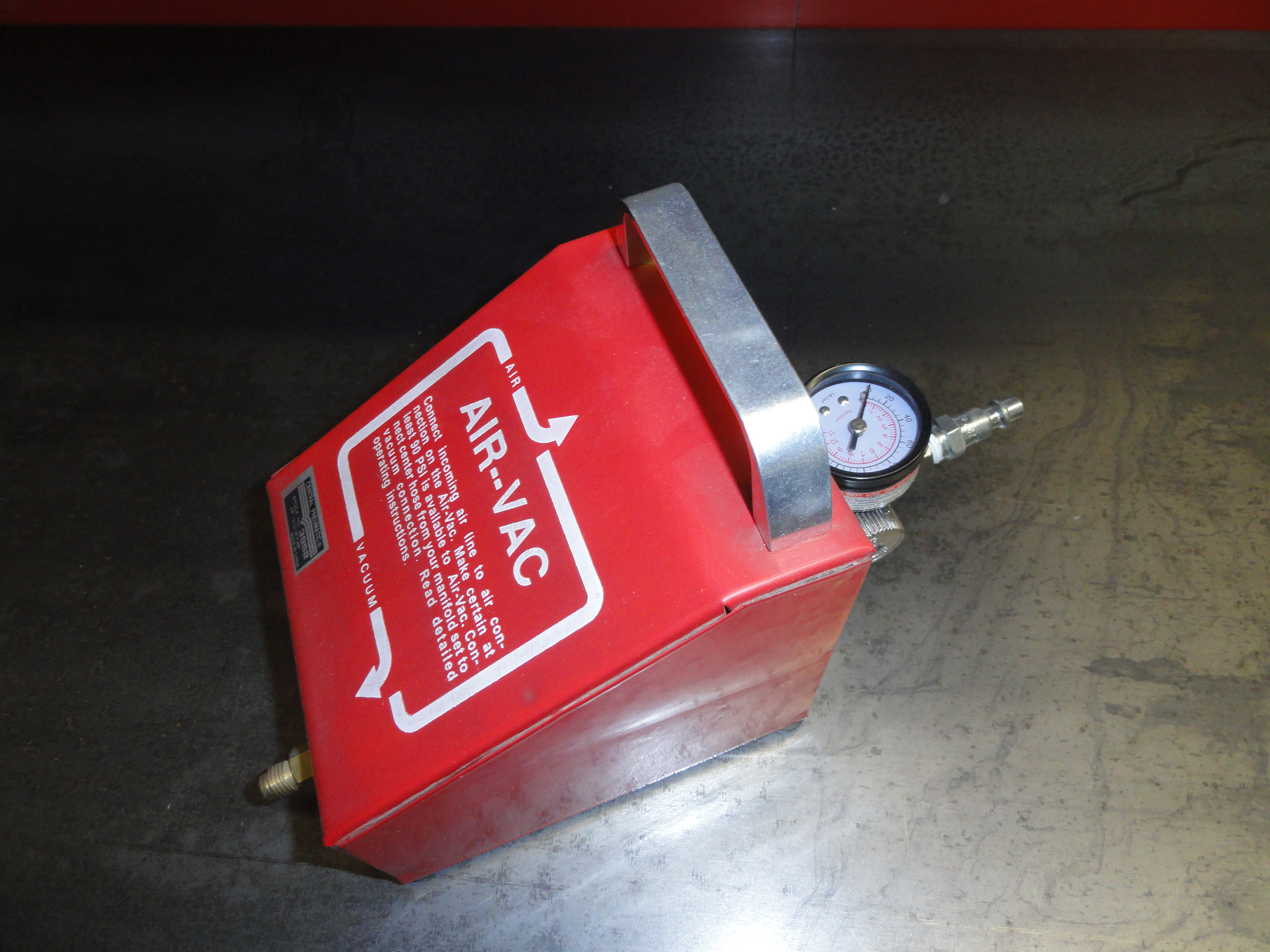
I have a box full of old vacuum advance units and I have found that to test them, a Harbor Freight Venturi Vacuum Box works really well to at least determine if the internal bellows has holes in them. These days, I do not use old ones, and very few of them that I have tested have proven to be working. Our vendors sell new ones and I just feel better purchasing new. Install your points and condenser if you go that route and Gap your points according to your shop manual for your engine, in our case .016. You can put your new rotor and cap on, and wait for the vacuum advance to arrive, then once you have that ready, you are ready for the engine.
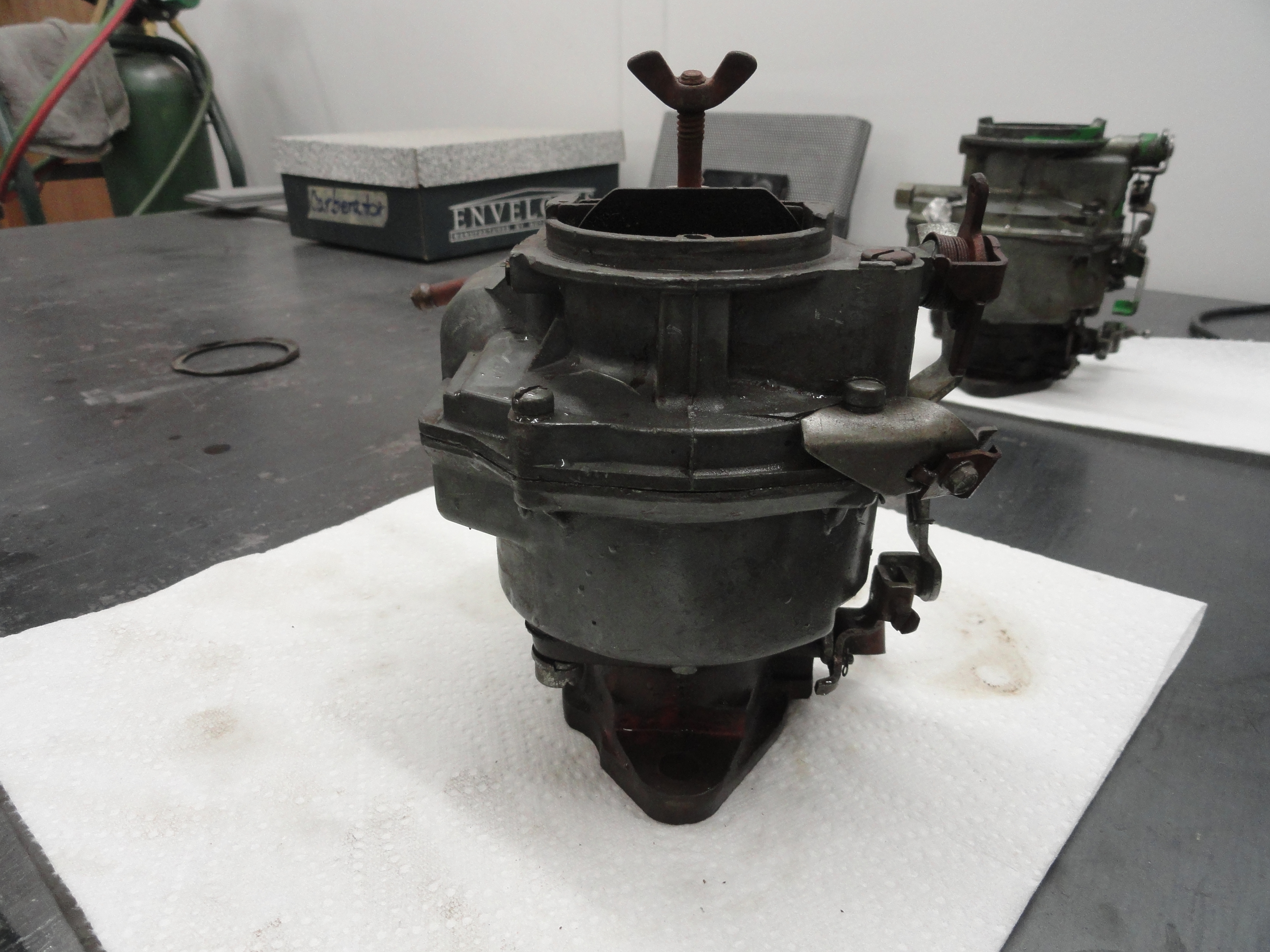
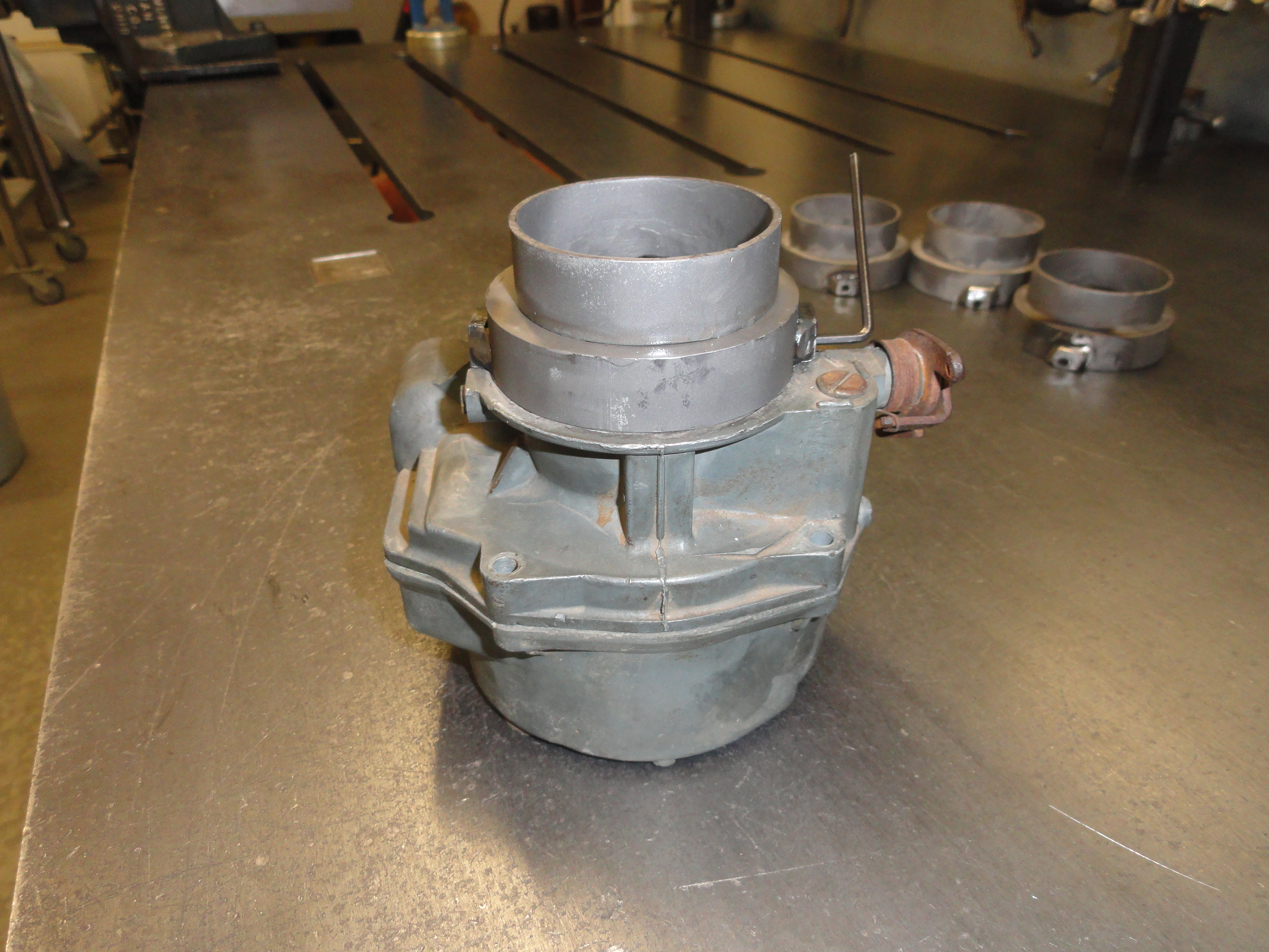
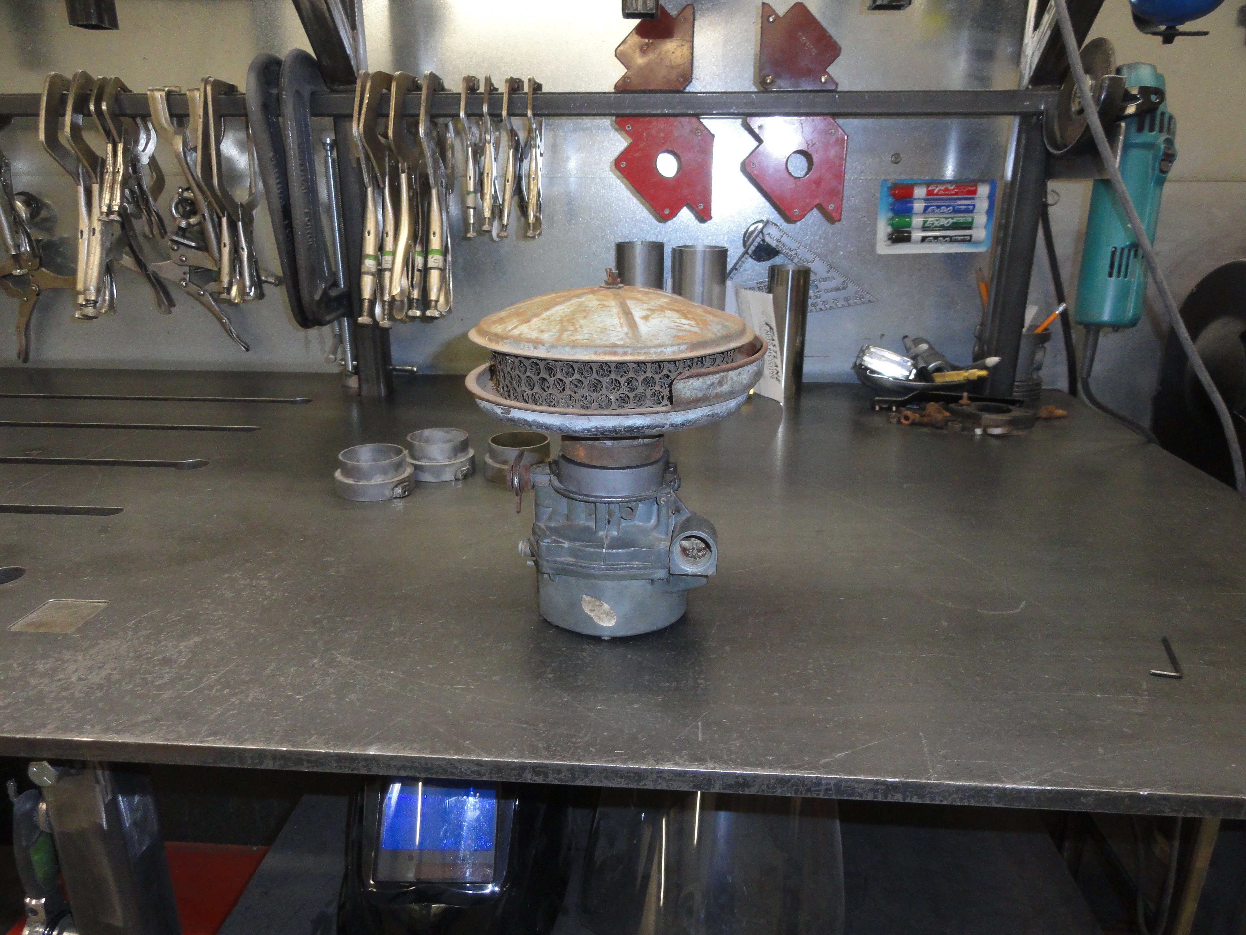
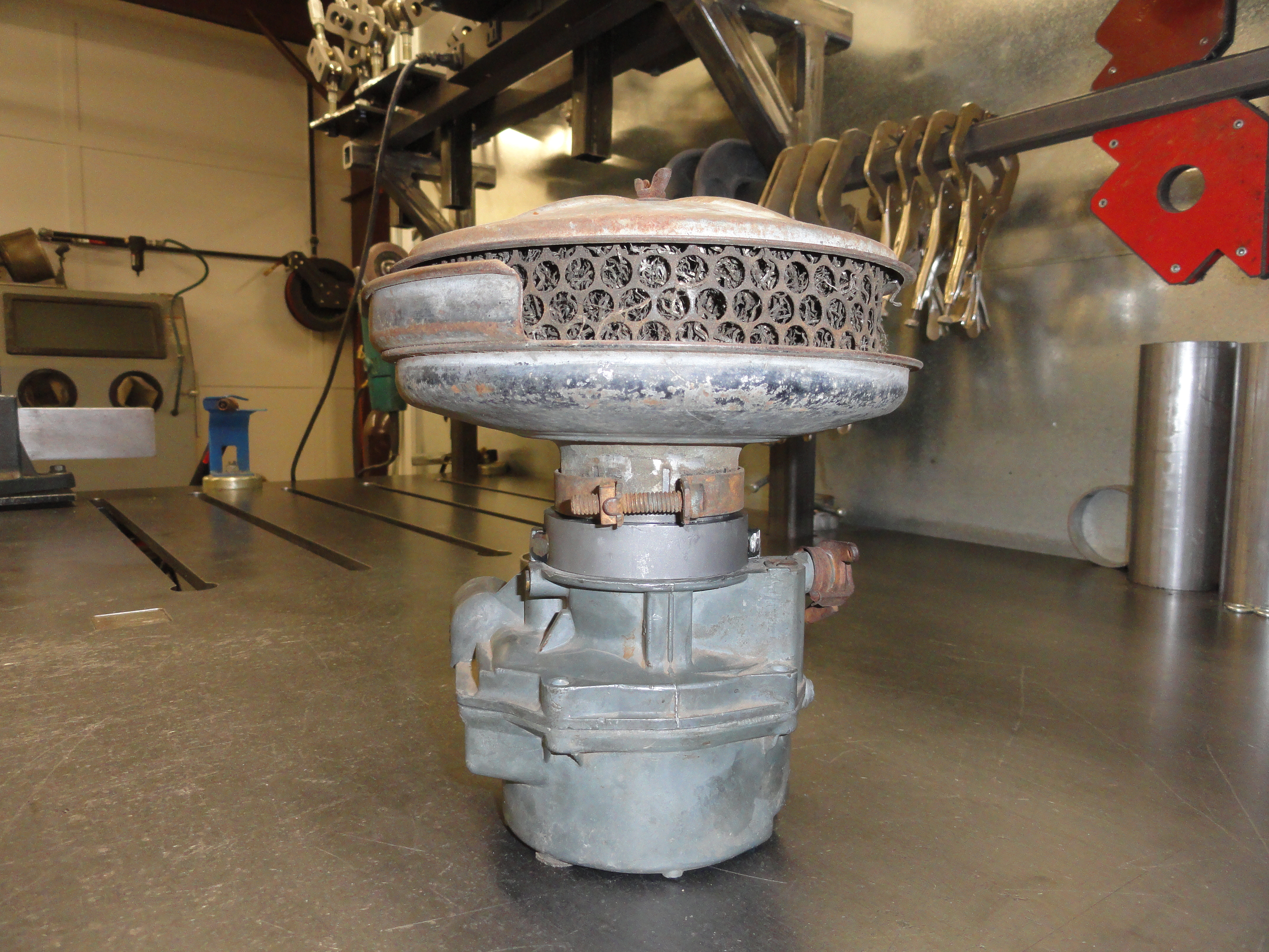
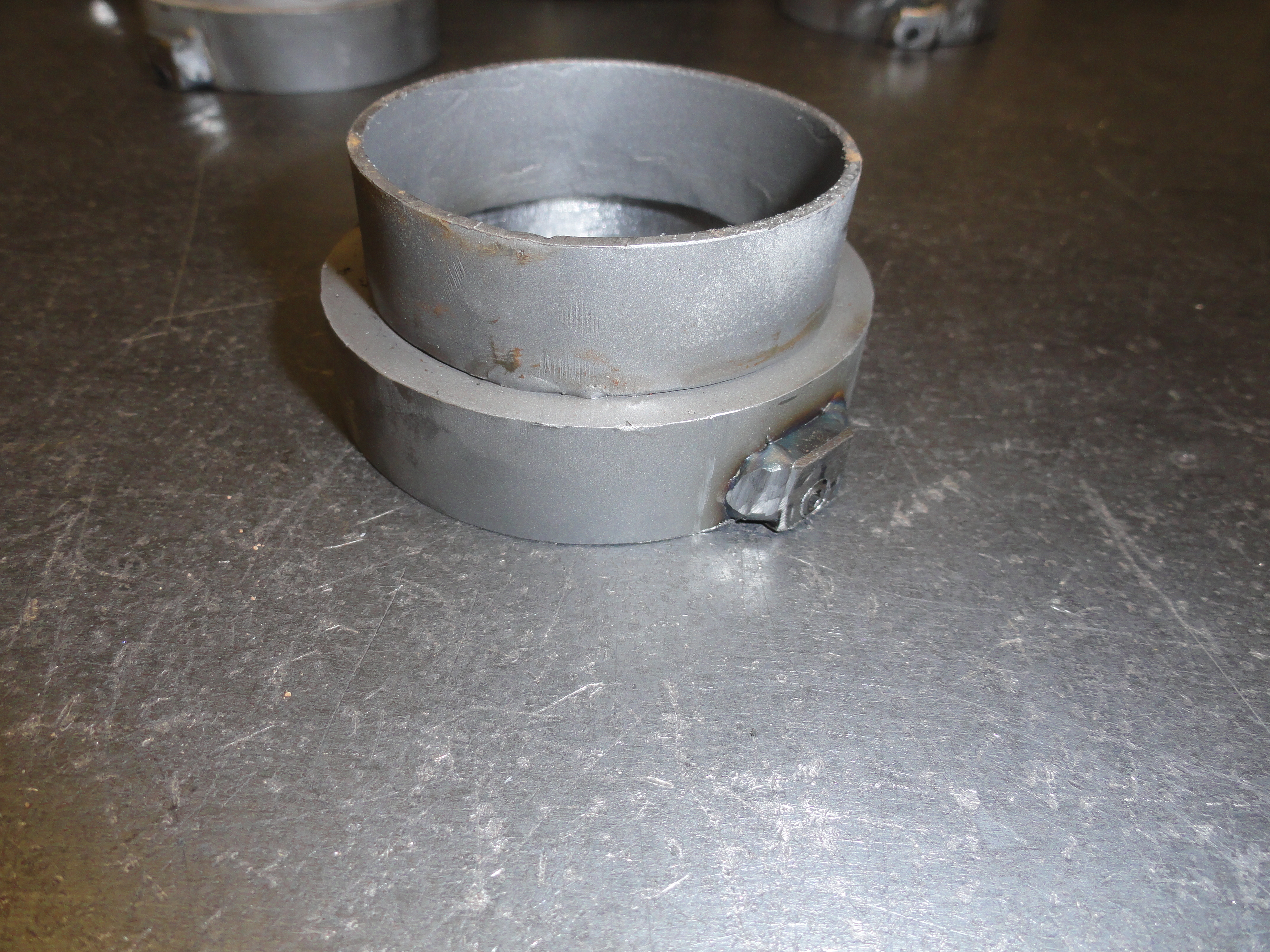
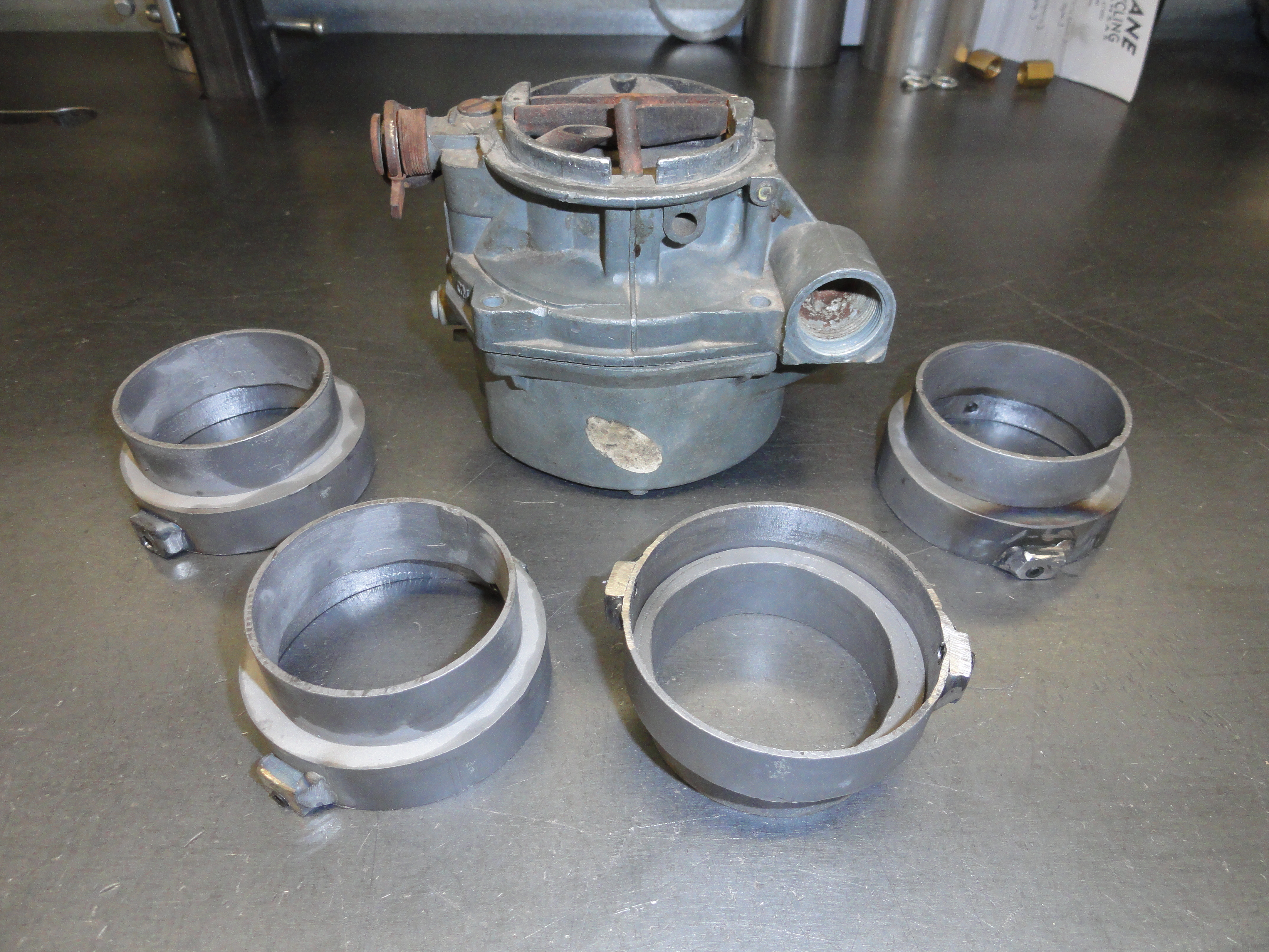
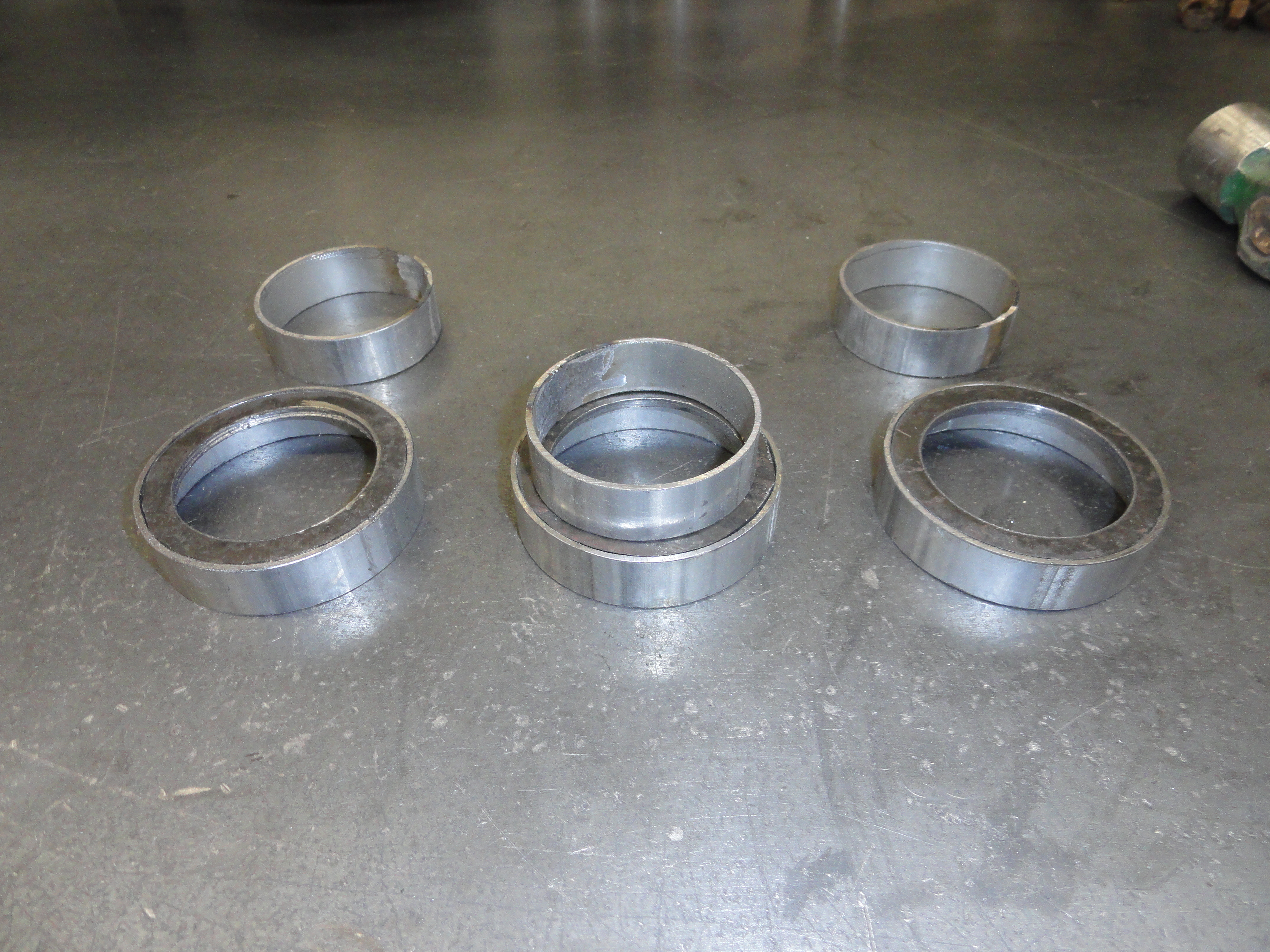
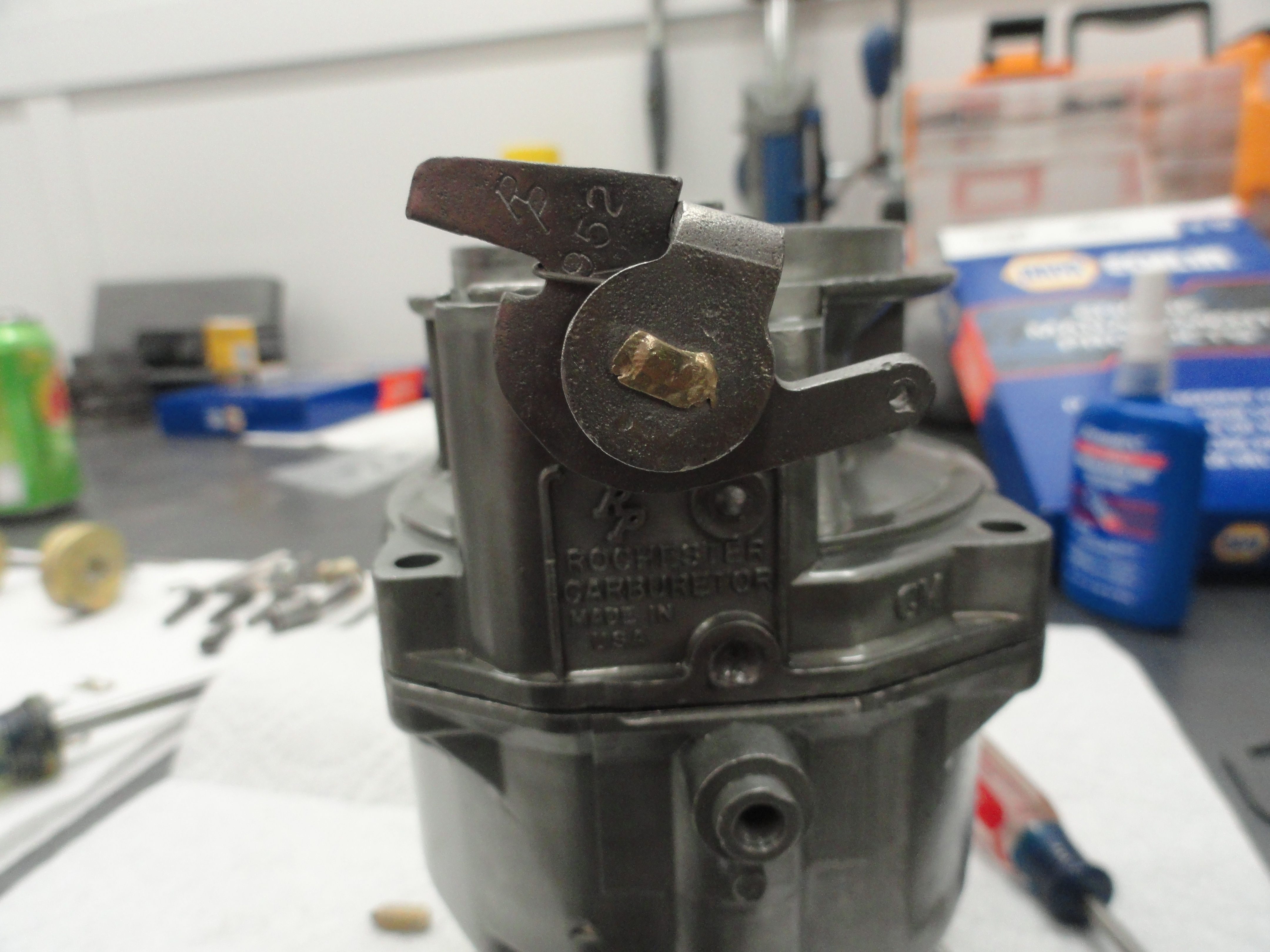
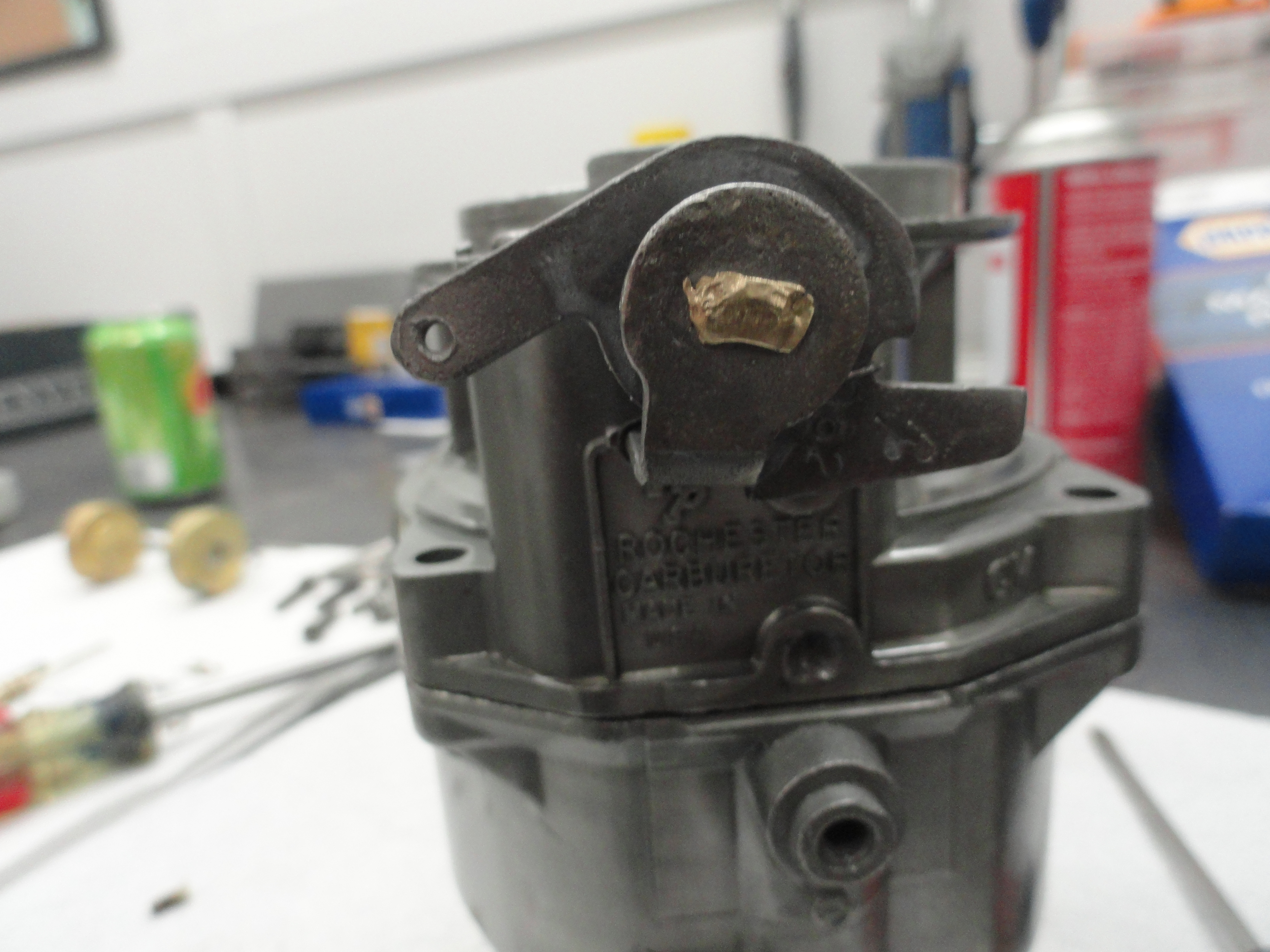
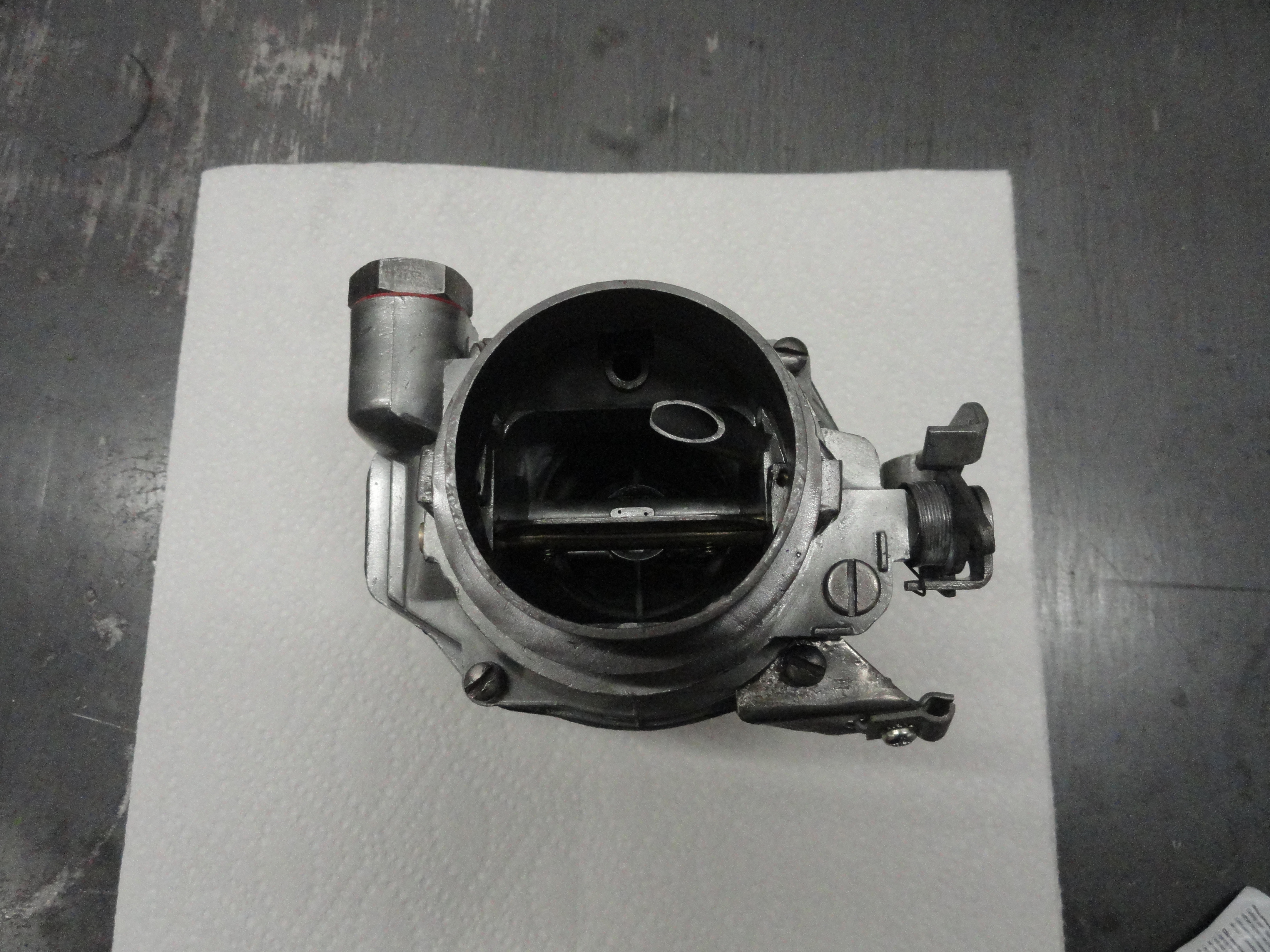
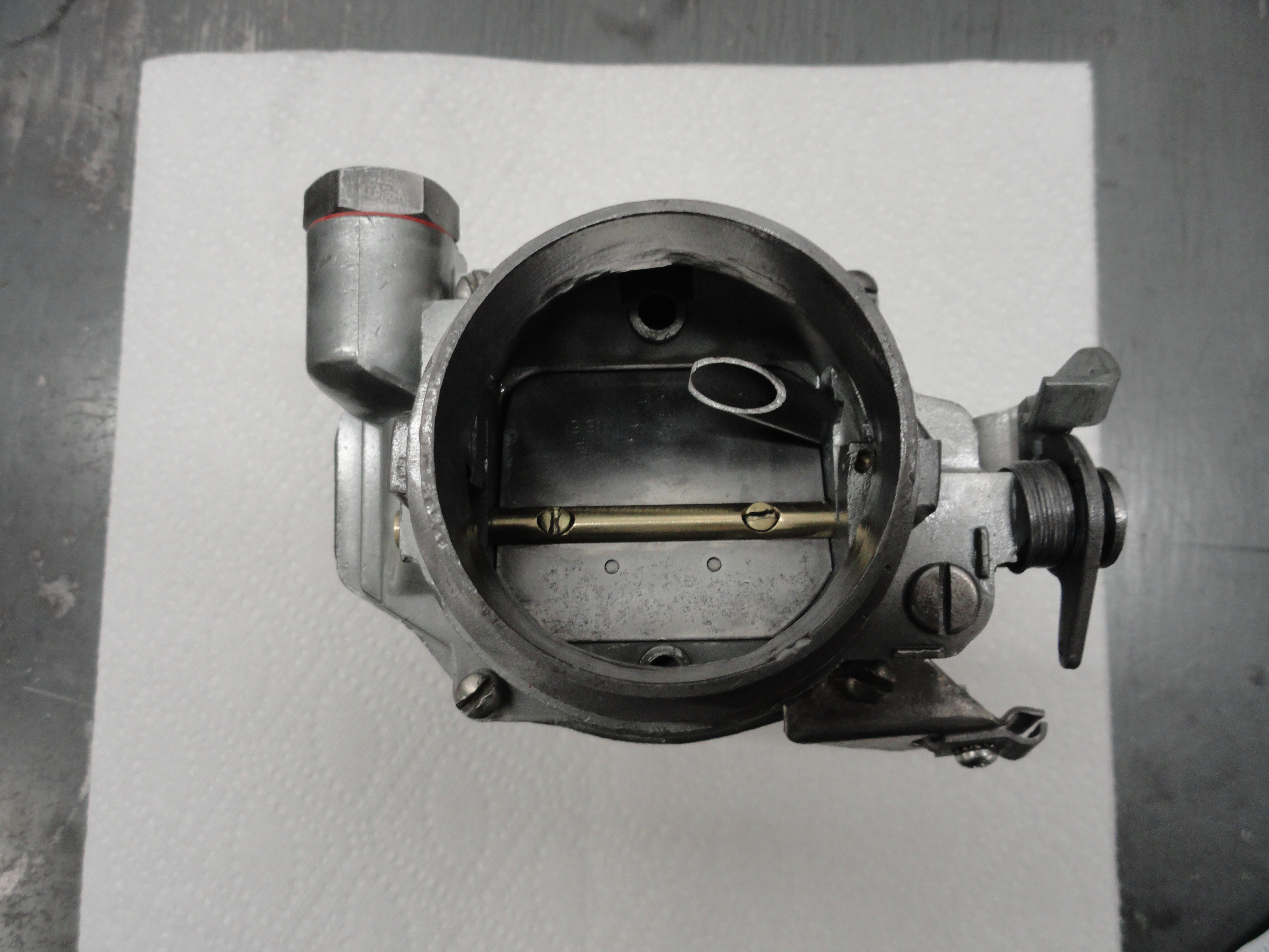
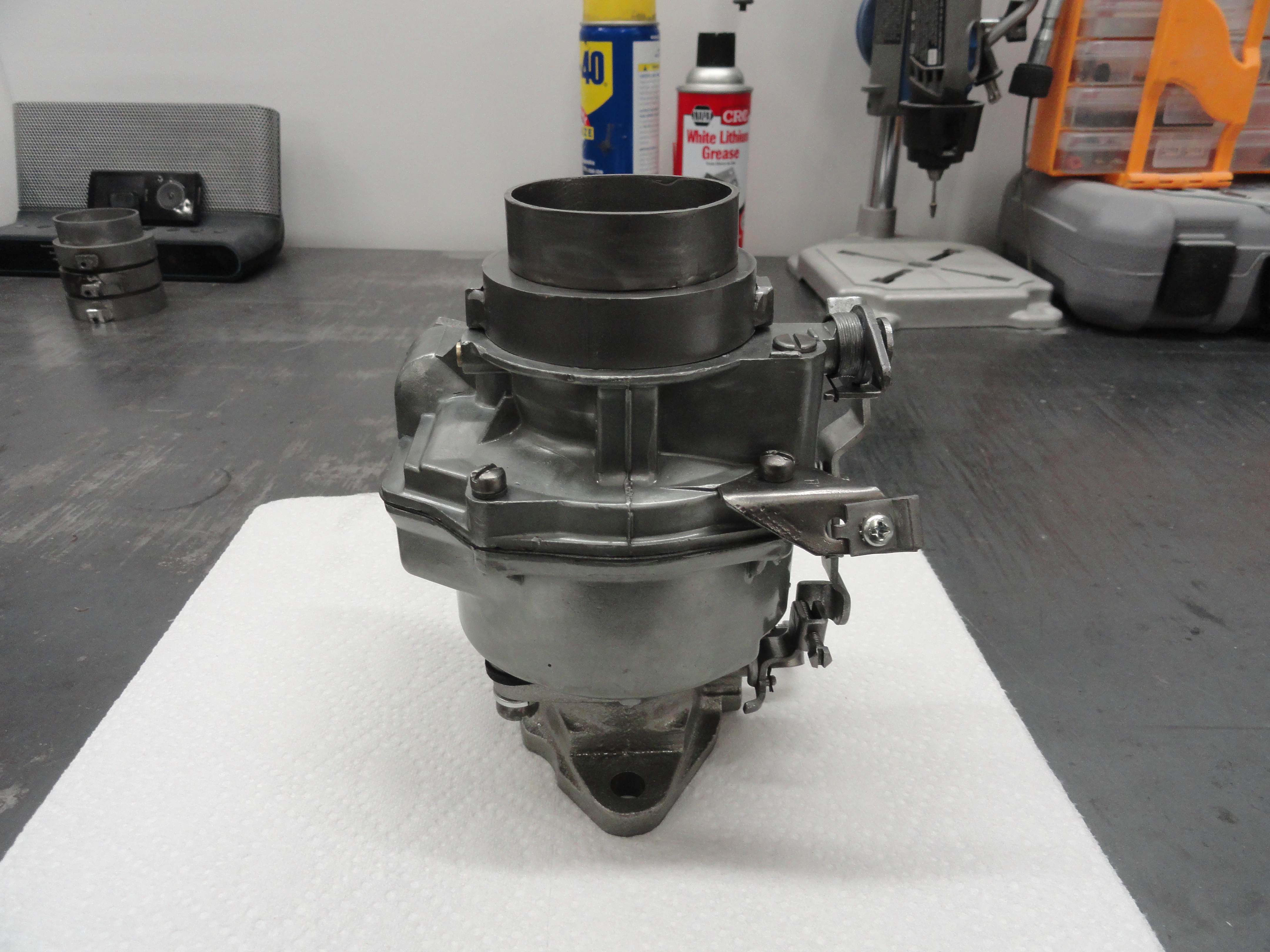
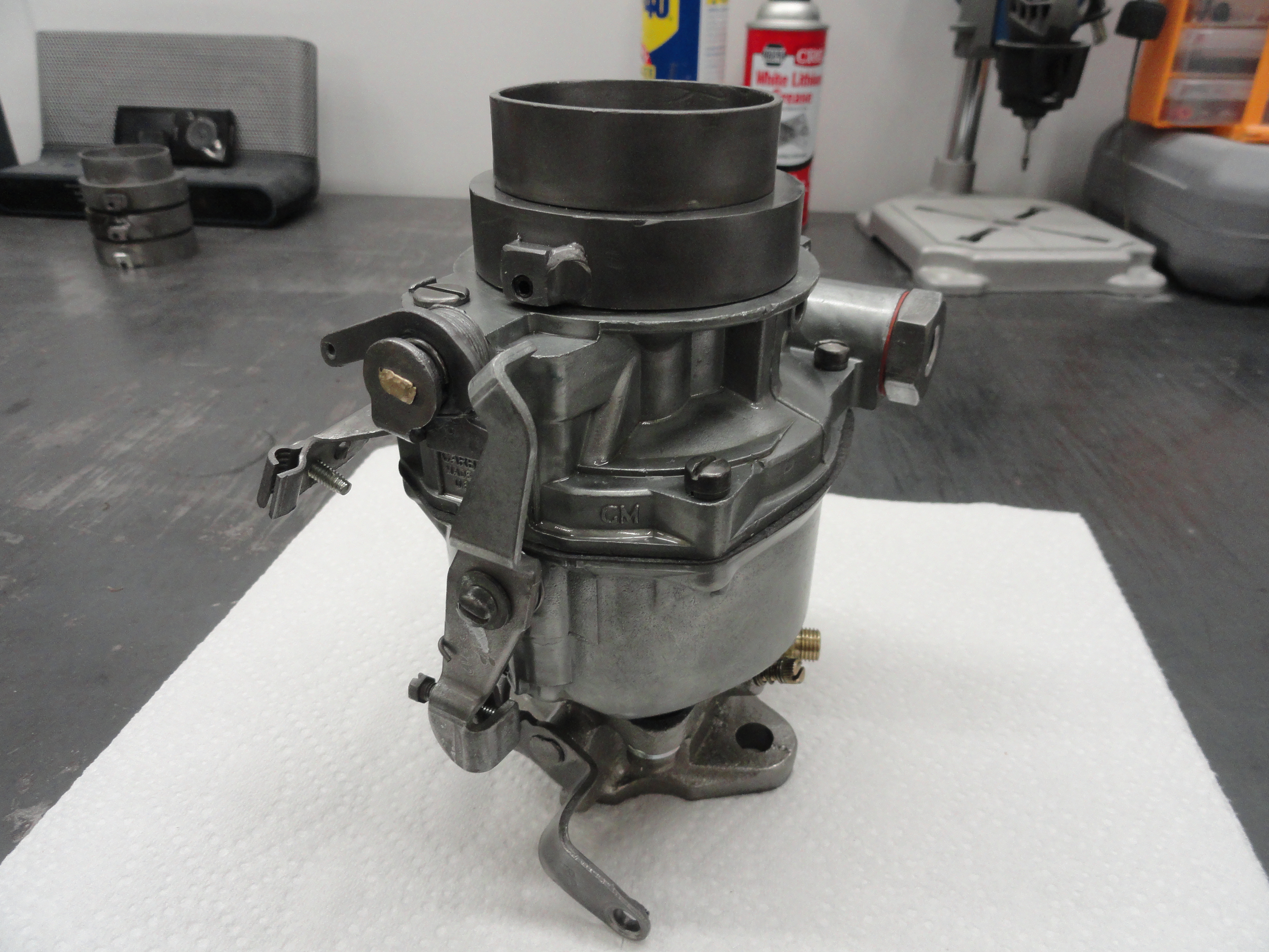
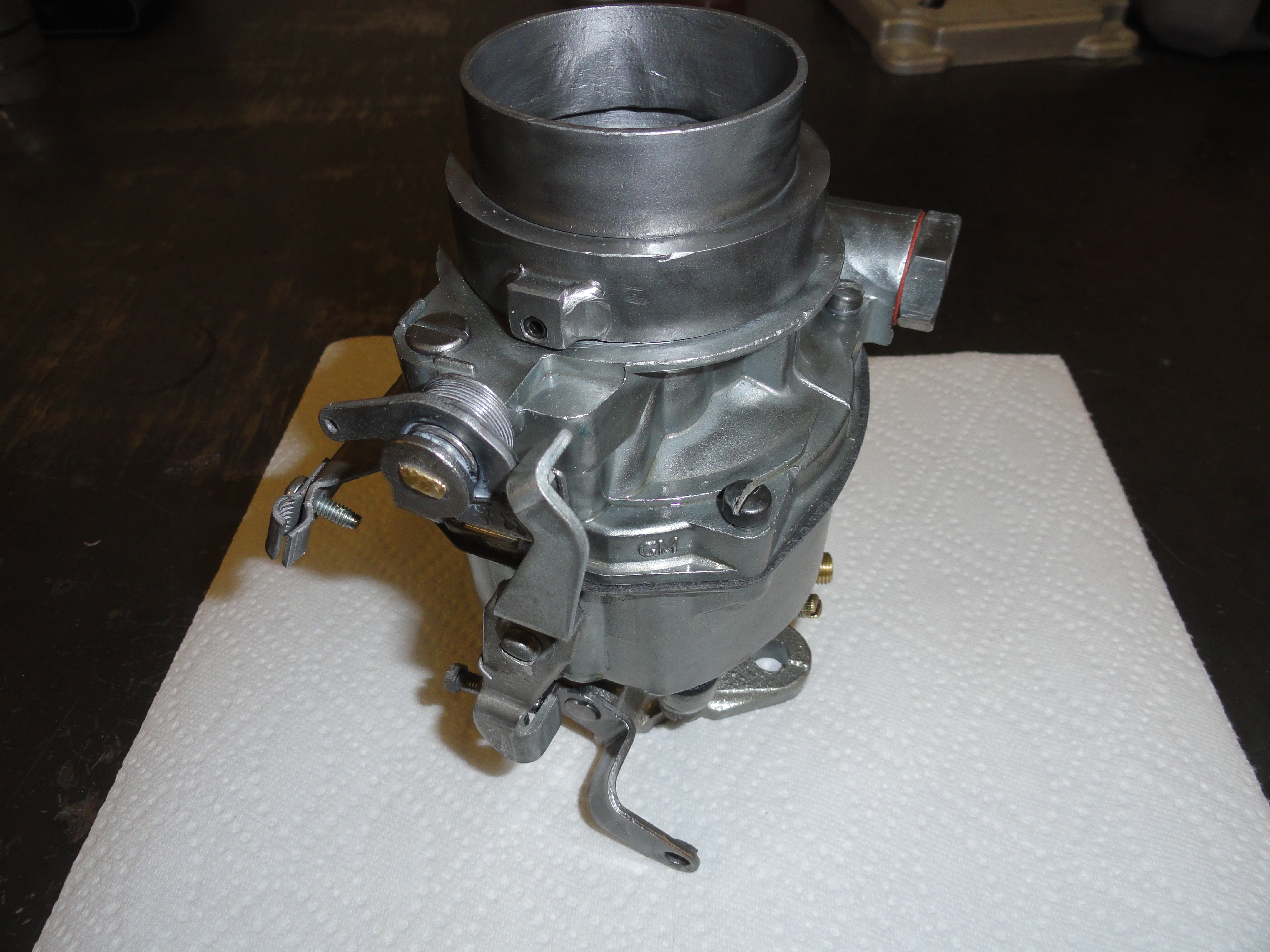
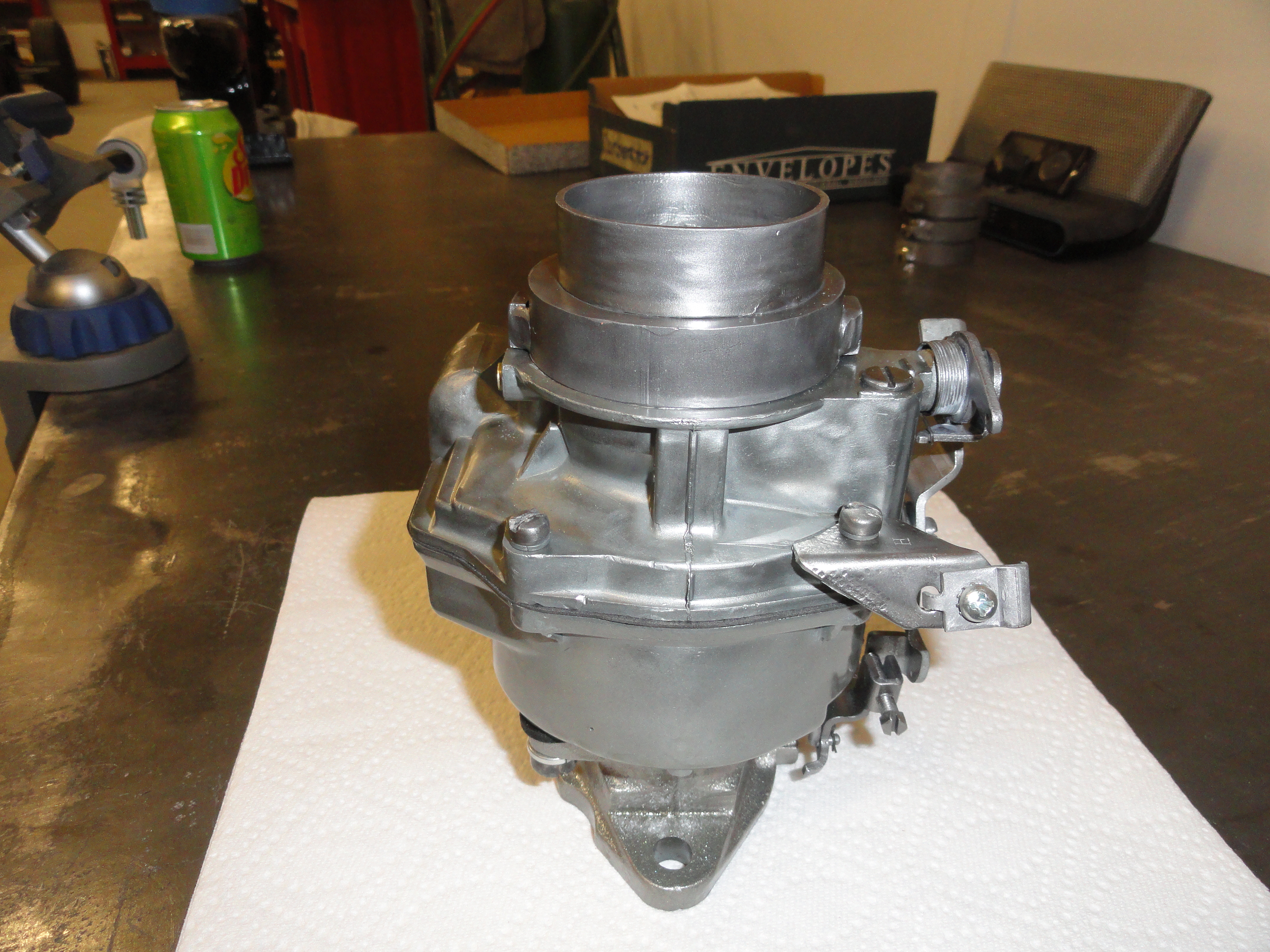
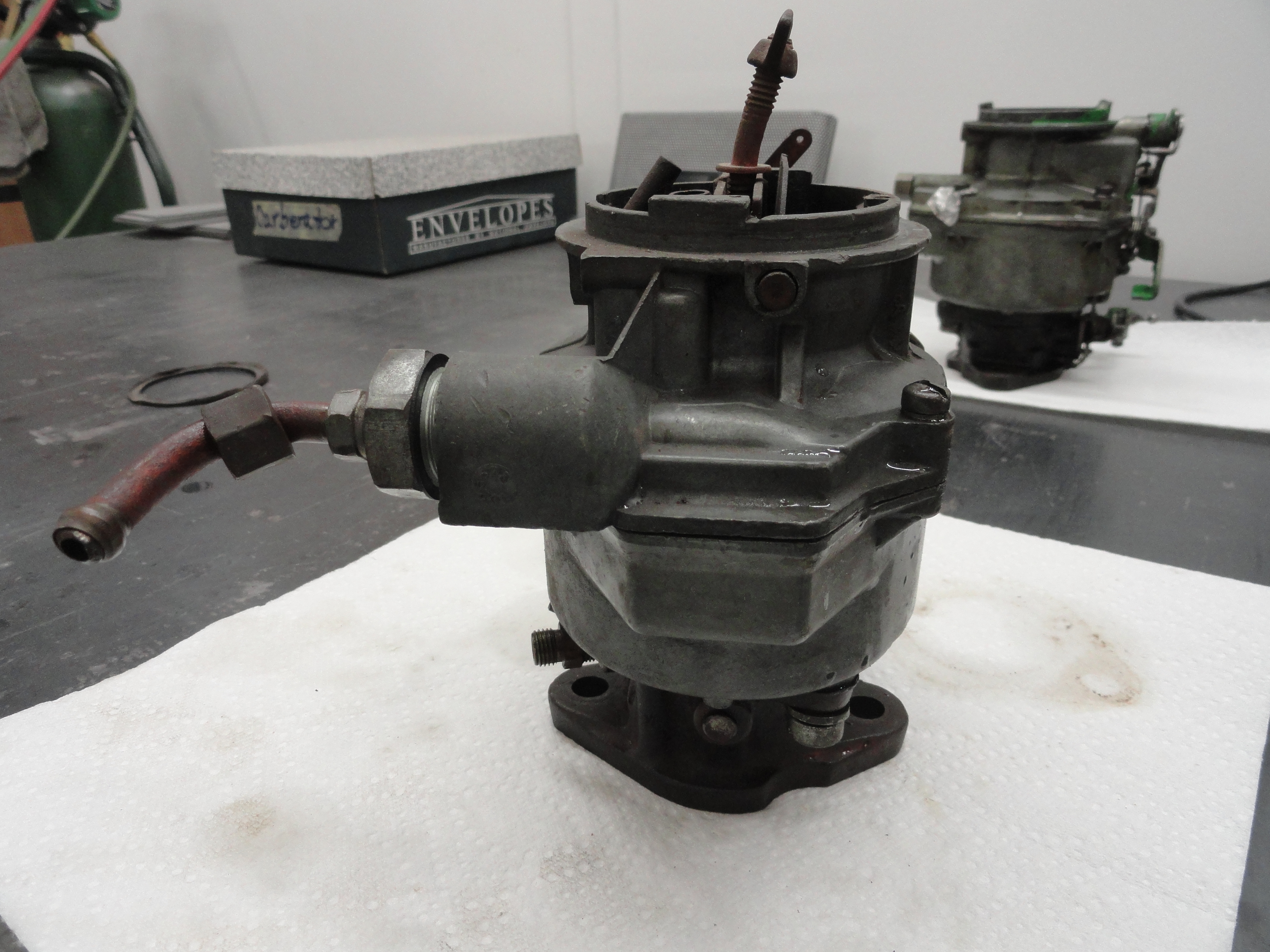
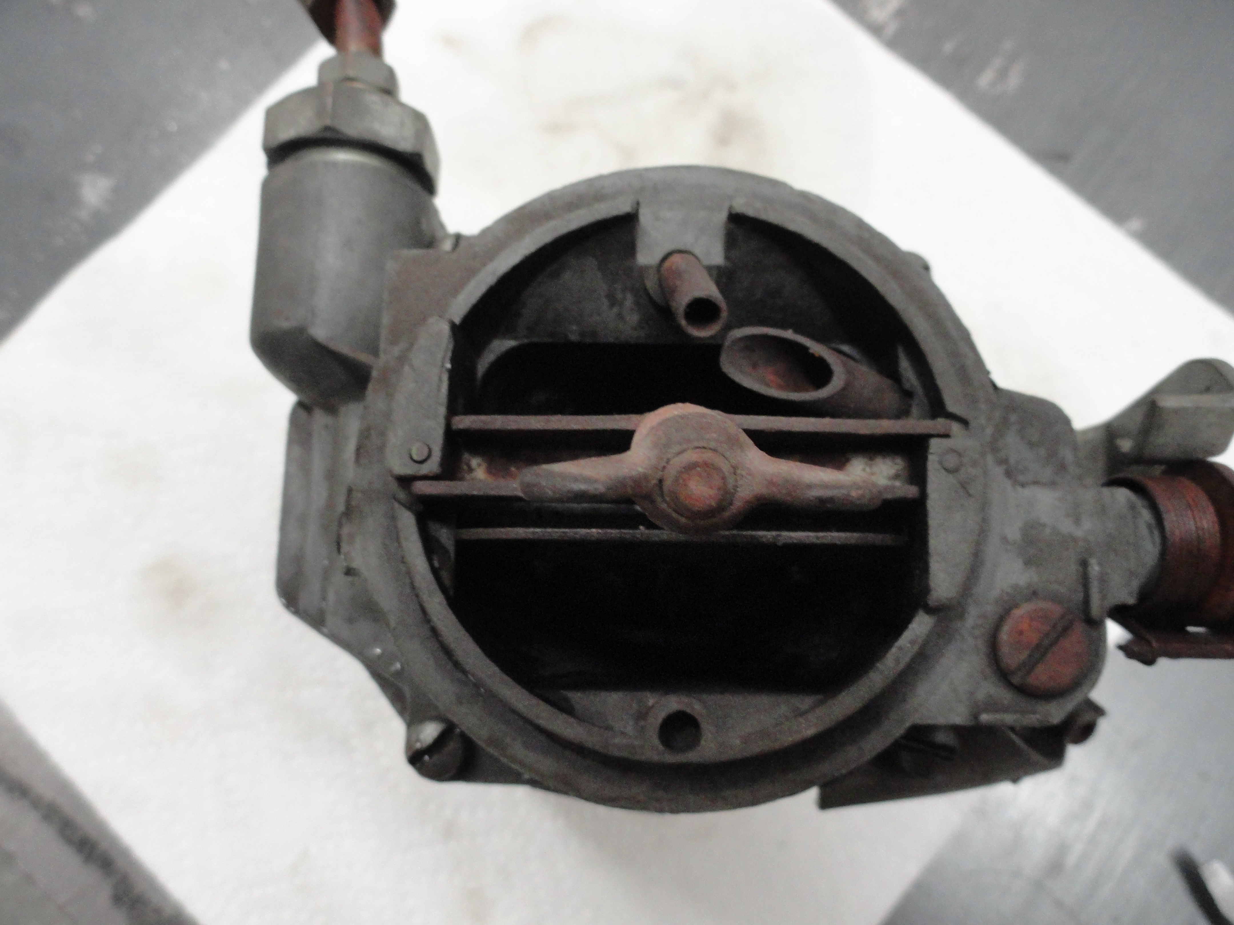
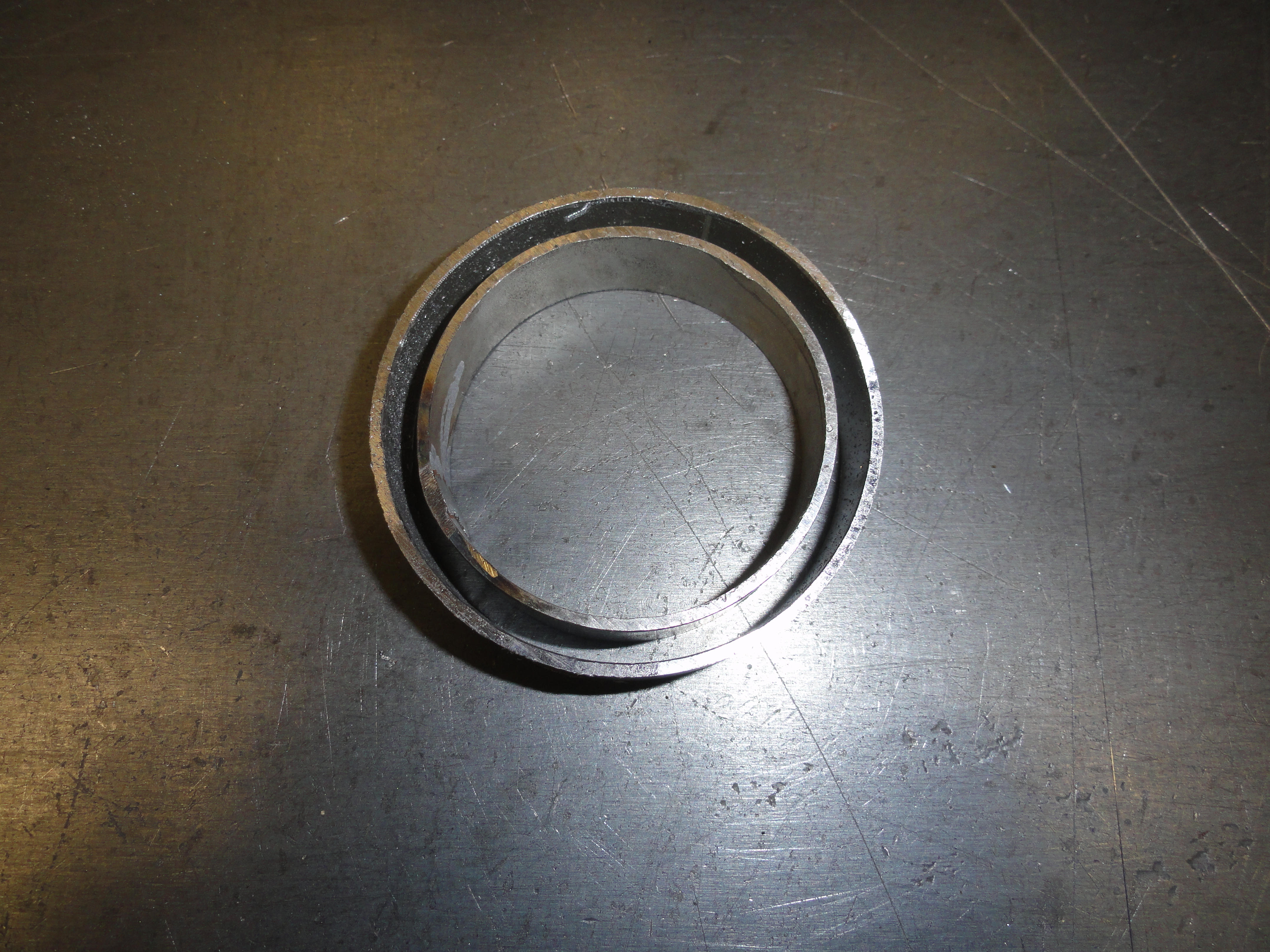
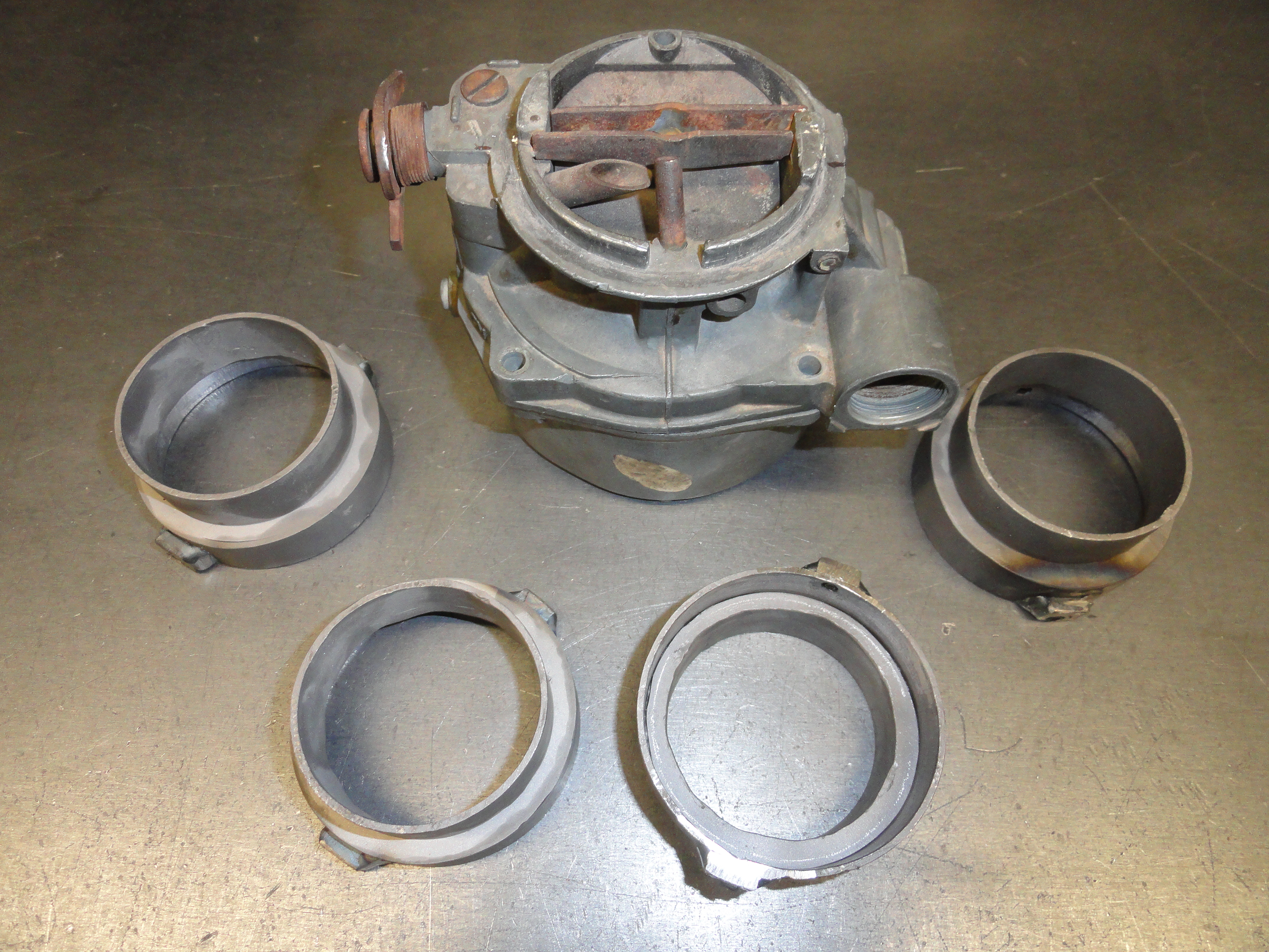
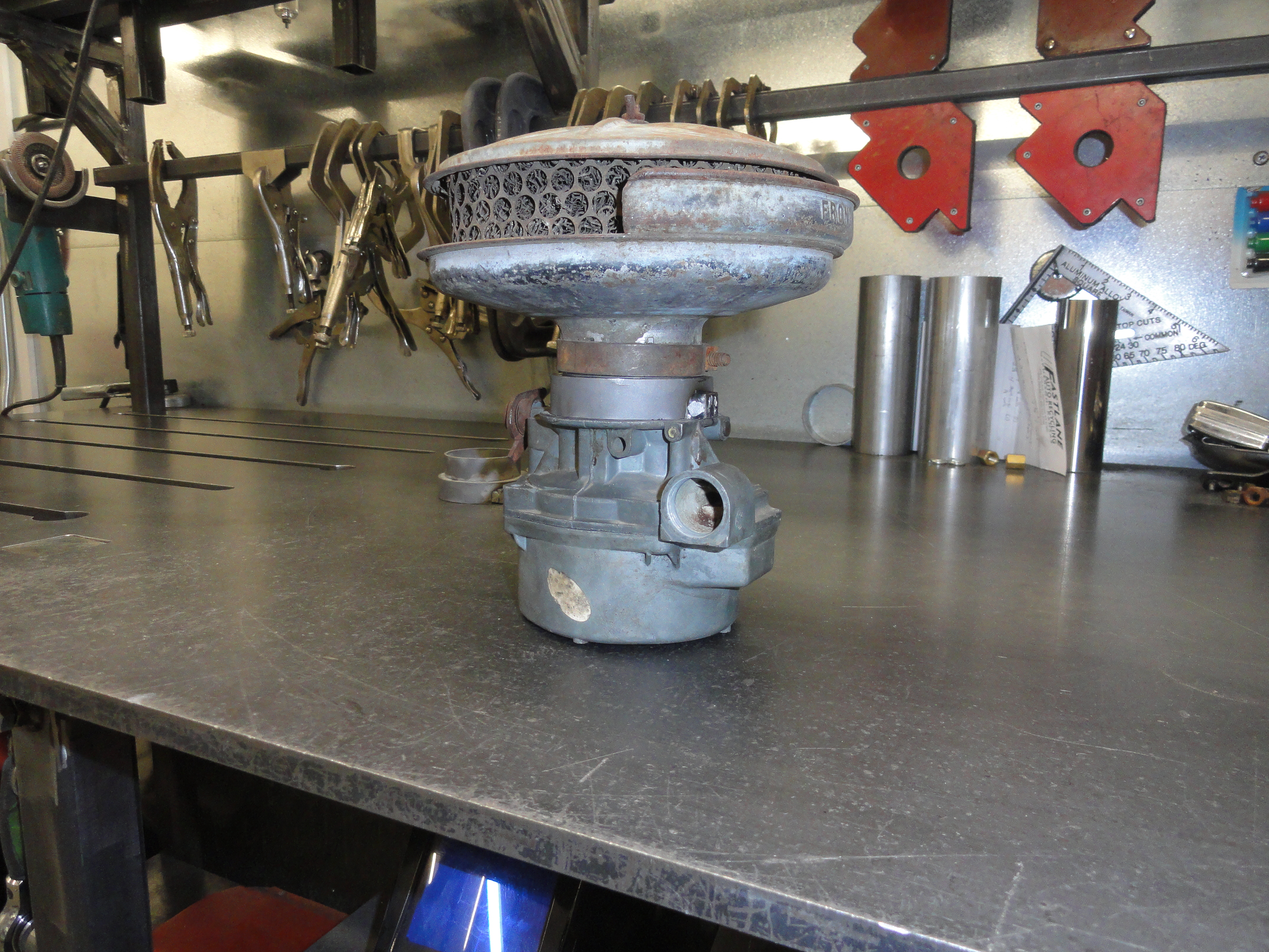
Since these engines are 1955-1962, I have several of the newer style Rochester B's laying around. The older style Rochester B Carbs had a smooth neck that you can place the older era Air Filter assemblies on by tightening a clamp around the throat. The newer style Rochester B Carbs have a center bar across the throat with a threaded nut. Since the older Air Filter units are not compatible with this new style, we have a choice. We can go with a newer style Air Filter Assembly, or we can adapt the carburetor to allow the use of the old style filter assembly. Your decision will have to do with what you are putting this engine IN. If you are putting it in a 47-55 truck, you want to use an Air Filter unit that was made for those years. I believe in choices, so the first thing we will do is to document how to make that adapter. The newer style throat is 2-5/8" while the older one is only 2-3/8". This does not mean the newer style throat sucks in more air because of the bridge across the throat for the attachment of the air filter unit, they are about the same. Left and right is the same carb with the mod mounted on the right.
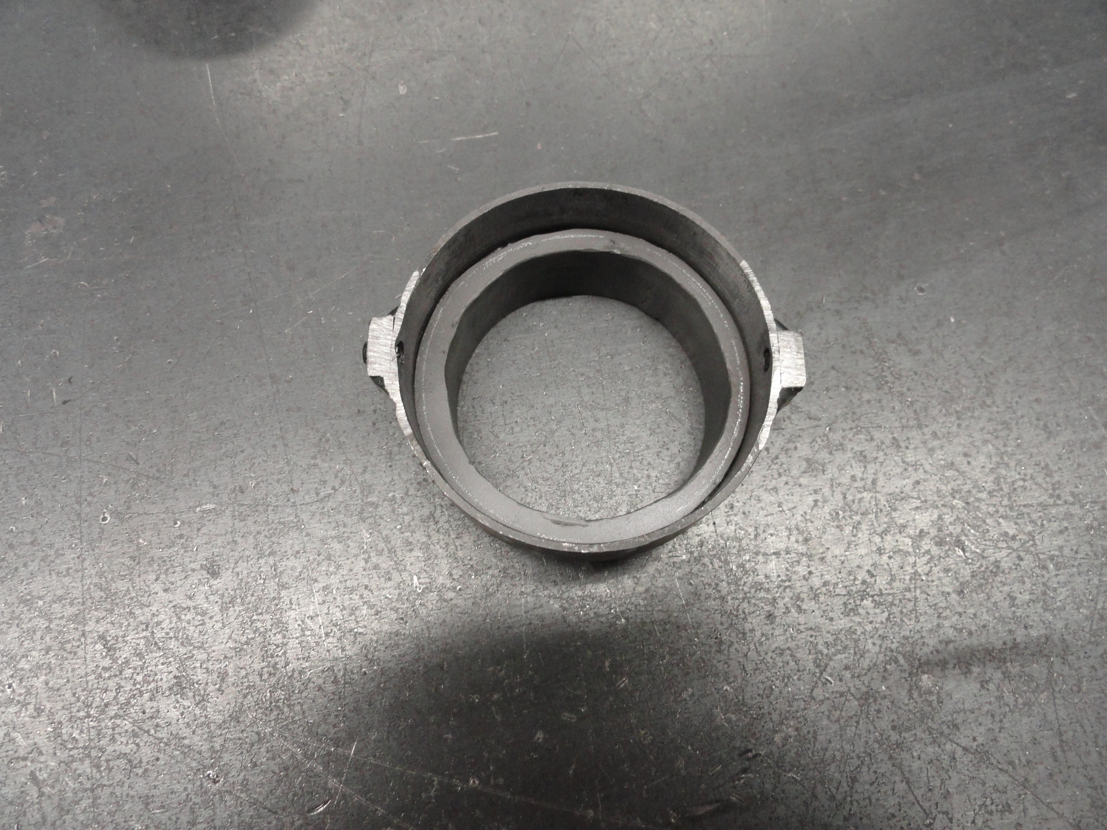
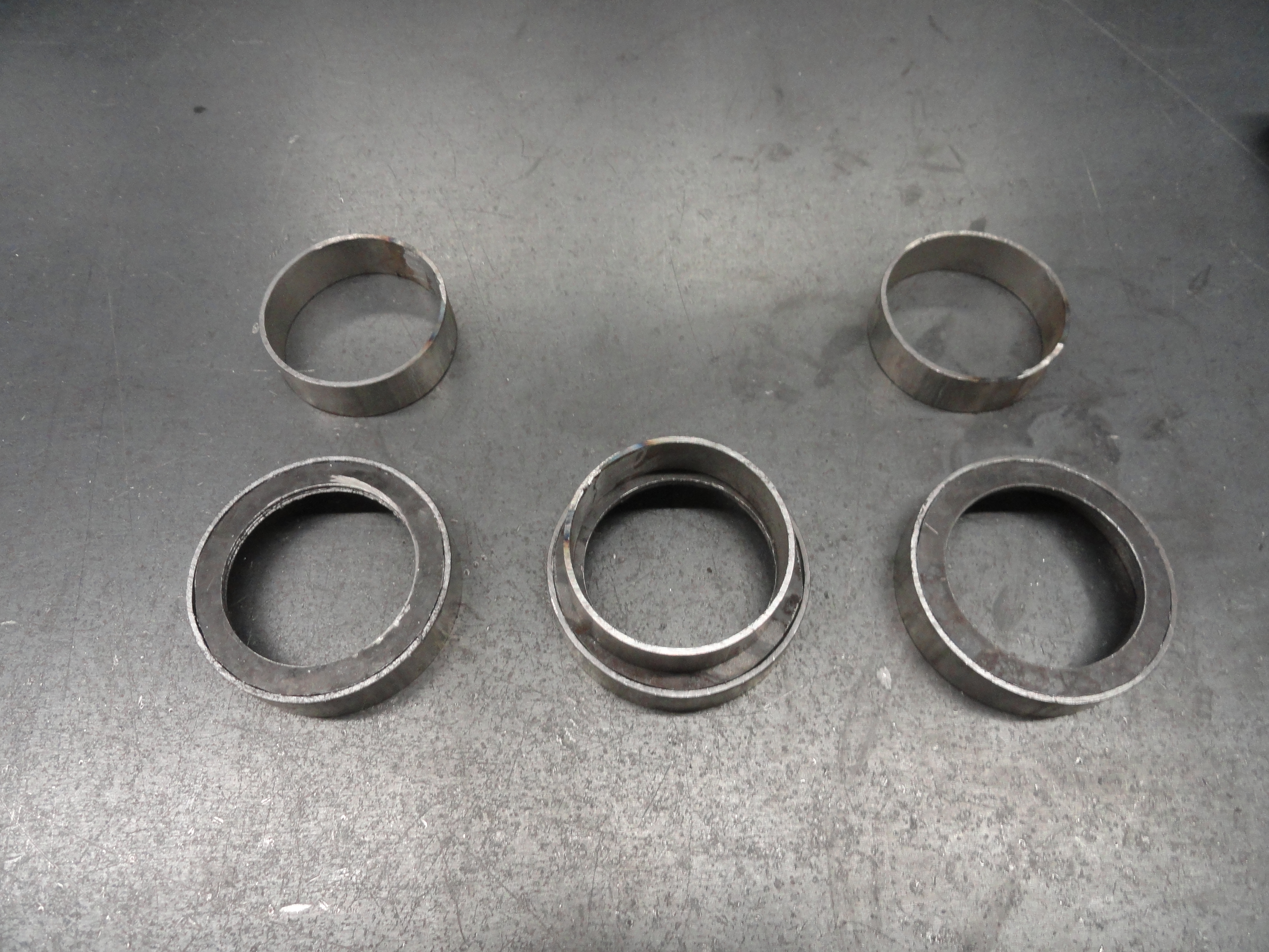
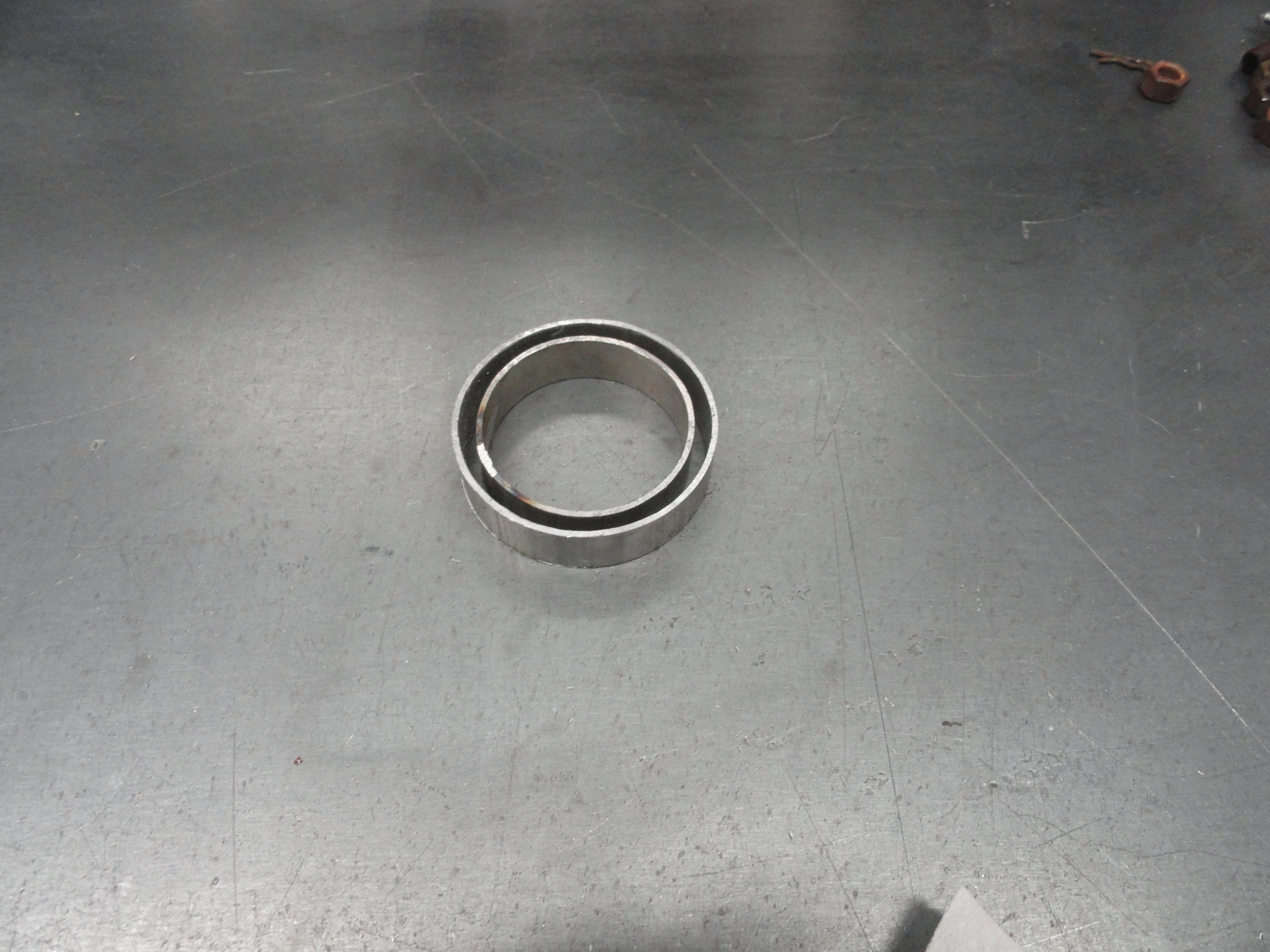
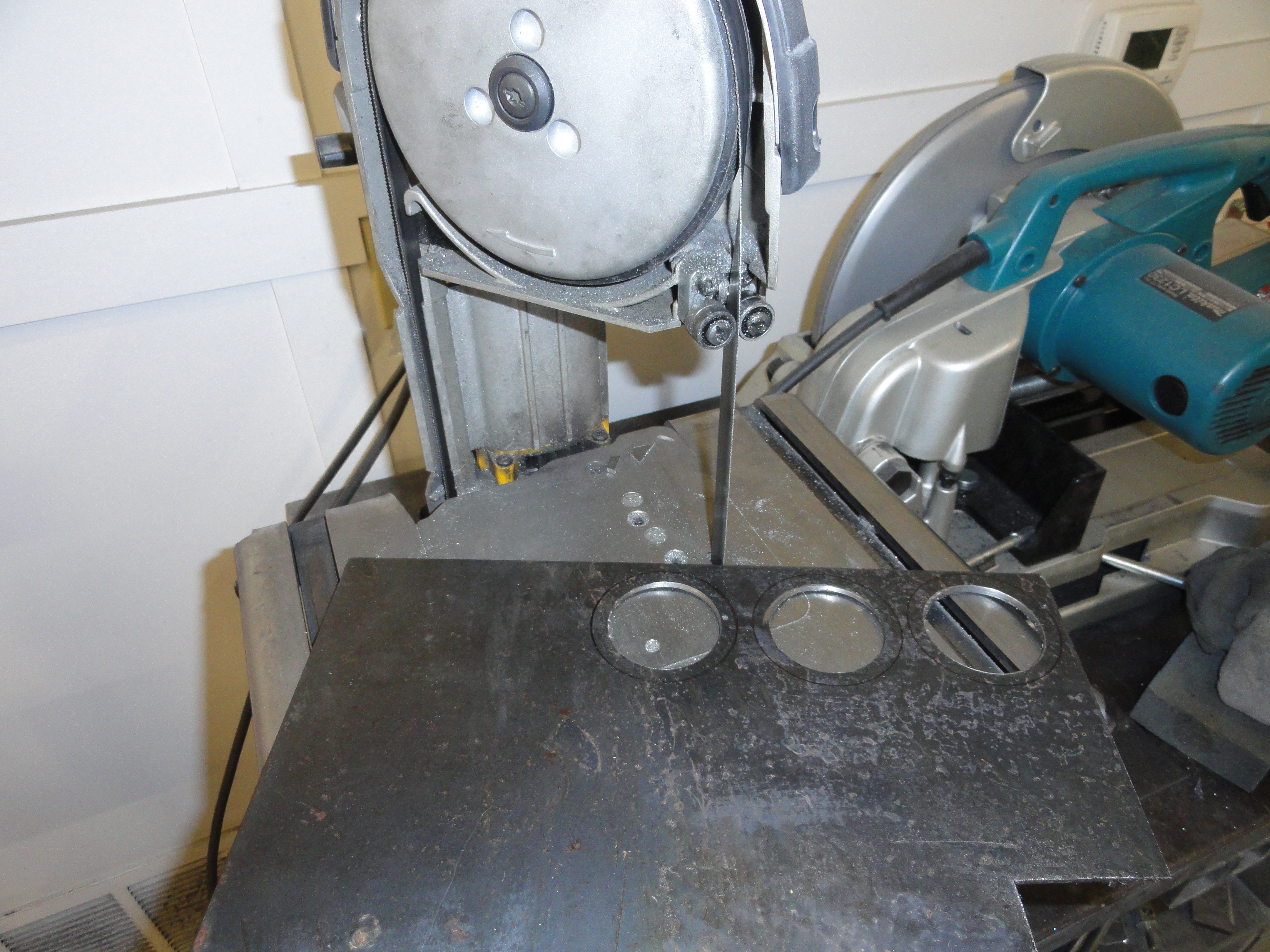
To modify the Carb for an older style filter, go to your local muffler shop and get two sizes of steel exhaust tubing. You will need 2-3/4" O.D. (2-5/8" I.D.") and 2-1/2" O.D. (2-3/8" I.D.). I just got 12 inches of each size so I could make a few extra ones. The overall height of this unit when it's over will be 1-1/4", so we don't need very much tubing for this. Cut a piece of the 2-3/4", 5/8" high. Cut a piece of the 2-1/2", also 5/8" high. Slice the 2-1/2" one in half down the seam. Using your Air Filter Assembly, resize the smaller one to fit snugly inside with the adjustment bolt turned about halfway out. This should be very close to 2-3/8". Make a mark on this sleeve and after cutting to size, weld it closed again. With two rings that are correct, we need to make a washer that will fill in the 1/4" gap completely. We want this washer to fit exactly inside the larger ring (so 2-5/8" O.D.) and exactly on top of the smaller one (so 2-1/4" I.D.). This strategy gives the larger ring the proper height and the small one too. Now with some strategic welding we can do this so that it functions perfectly. Start with the large ring and place the washer inside level with the lip, then weld it on the outside only. Get good penetration so that after you are done grinding all of the weld back off level, it is still very secure. Once you are done grinding it back smooth again, turn it upside down placing the smaller ring on the table, but in the center of the larger ring. This makes it easier to get the MIG wand in the correct position for welding just inside the hole. Again good penetration is essential because all of that weld will be ground back smooth too. Weld it slowly and use proper welding procedures to avoid warping.
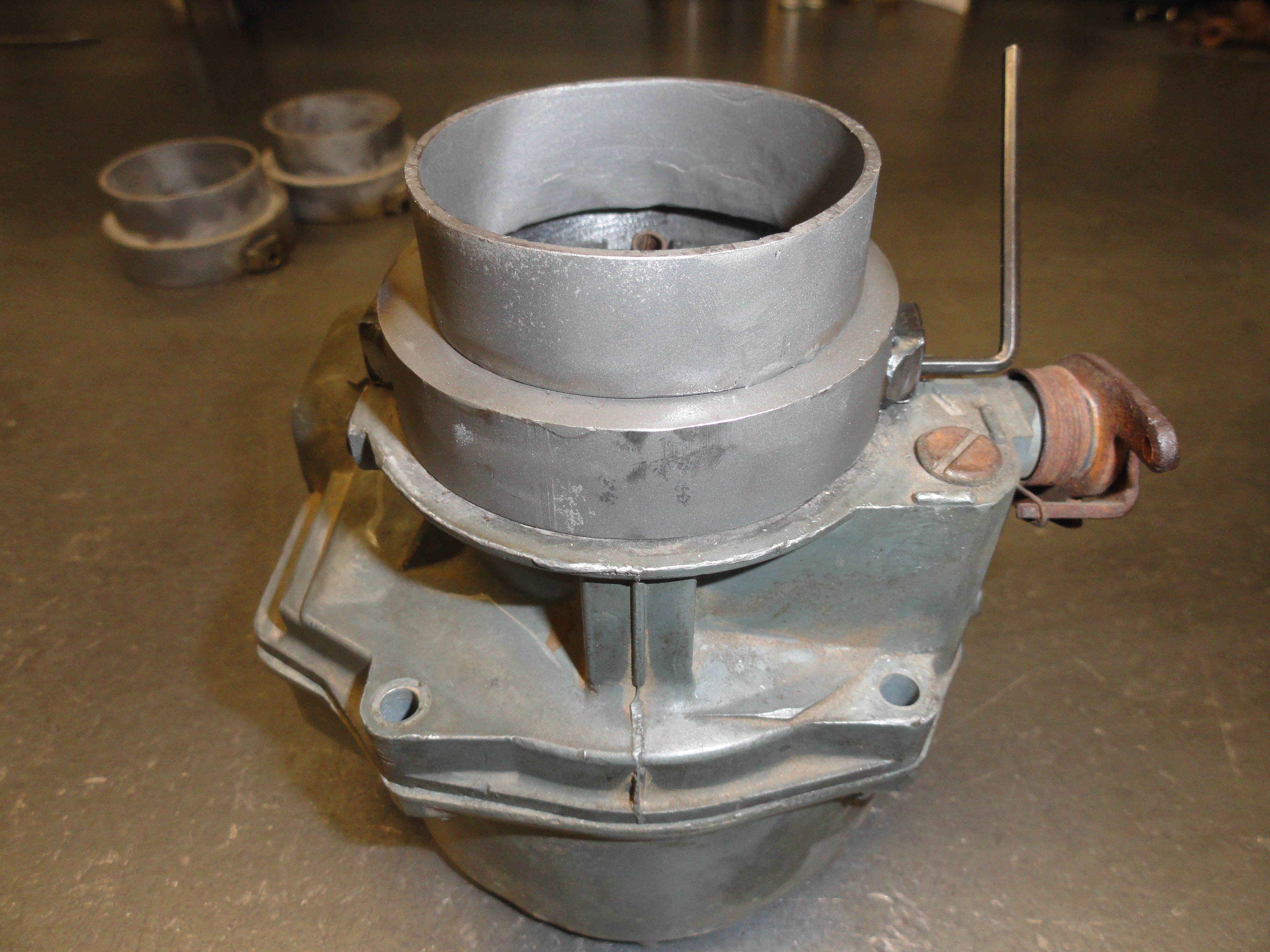
Test fit the unit to make sure it fits properly. If the larger one will not fit over the carb but just barely, grind out the seam and it should fit perfectly. Once you have a good test fit, we need to make sure this thing doesn't come off the engine. To make SURE this won't happen, we need to weld a 1/4" nut near the bottom and exactly where the thicker part of the carb flange is located on both sides. Mark as in the center of the meatiest part of the throat and 3/16" up on both sides about where the old mounting bridge is located, then place the nut where you want to weld it, and then FILL the 1/4" hole as if using it for a spot weld. Fill it with weld so we can re-drill for a #10 Allen style set screw. Once it's cool, mark the center of it for drilling and center punch it. Mark 3/16" from the bottom in the center of the nut. This should place the hole exactly where we want it. Drill using a #21 bit used for a #10-32 tap. Tap and place the unit on top of the carb in the correct location. Mark through the hole a mark on the carb. Using a 1/8" drill bit, put a shallow dimple (less than a 1/16") to allow the setscrew to protrude just a little bit inside the carb. Install the setscrew using LocTite. Now we can use these newer style carbs with an older vintage filter assembly or a newer one. The choice is now yours!
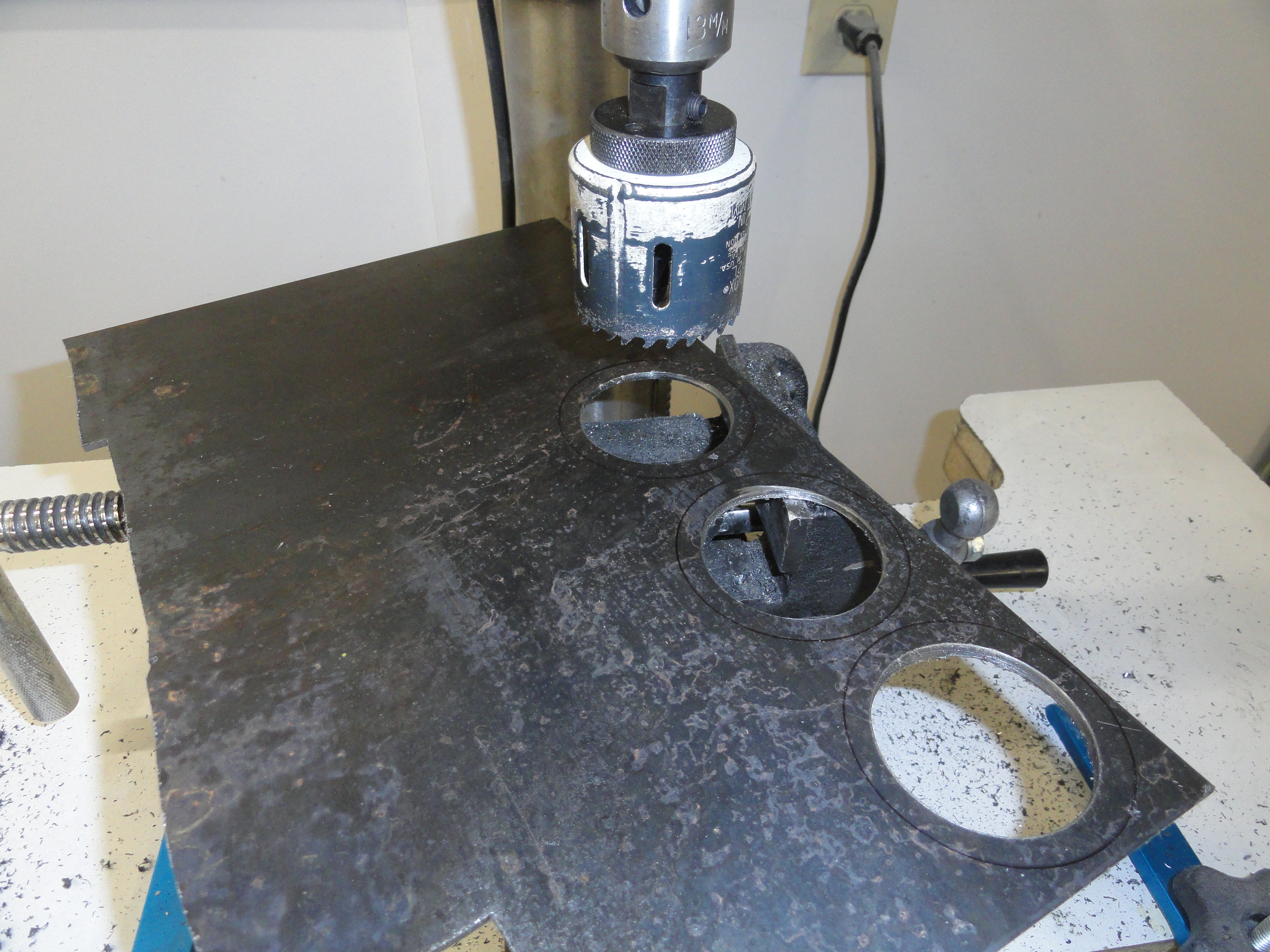
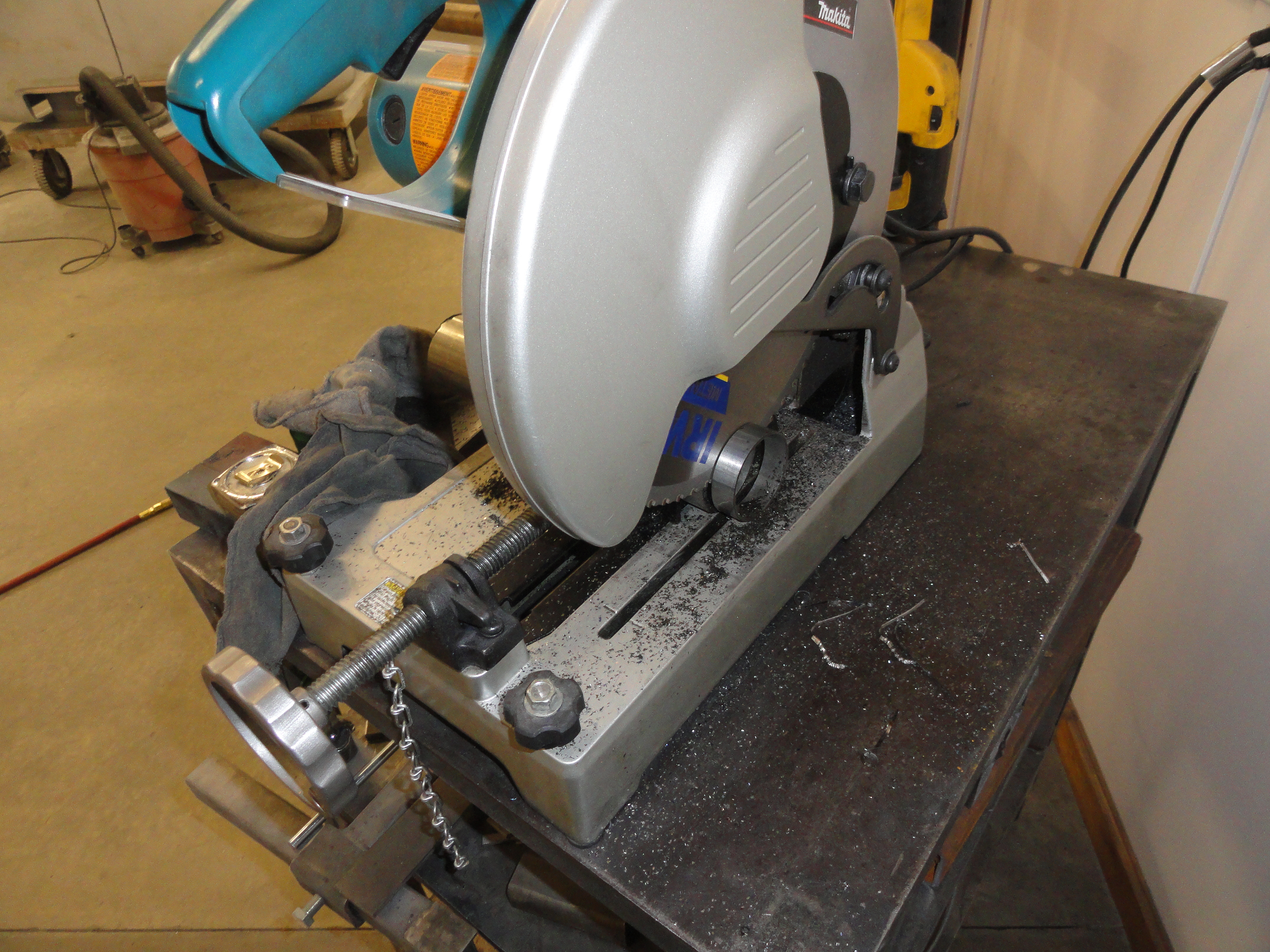
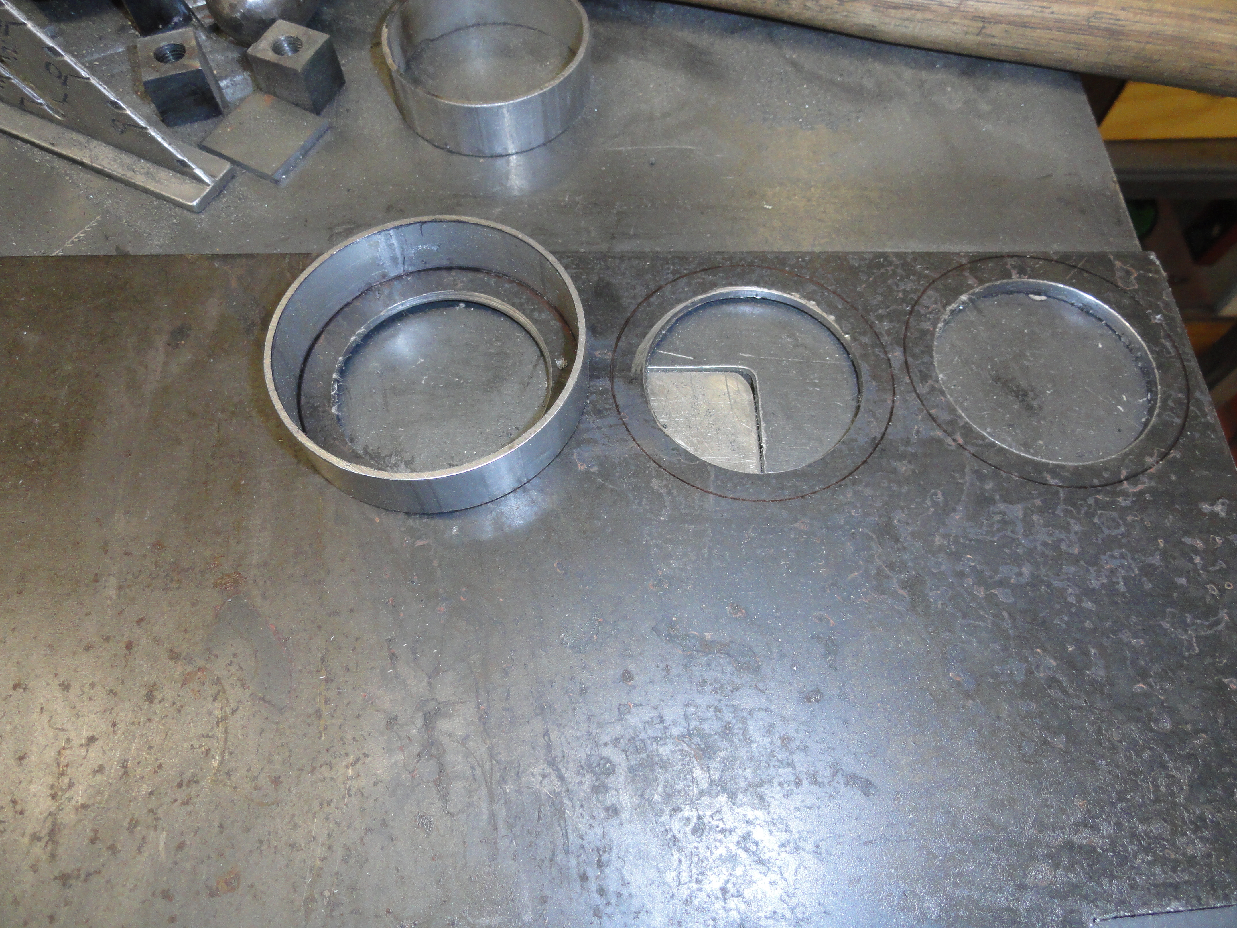
The above modification is very solid and with loctite on those Allen setscrews, it will provide you with years of service. This mod was very difficult for me because of my lack of sophisticated machinery. It's not any big deal to slice through some exhaust pipe, but it IS pretty difficult to make your own 2-5/8" OD, 2-1/4" ID washers. All I had to do it was a 2 inch hole saw! So, cut the holes, trace around the INSIDE of the larger ring, then use a PortaBand to cut a round circle. Then, use a 3 inch air rasp to whittle away the 1/4" that your hole saw didn't get. I am all for getting the right tool for the job, but I haven't found an economic way of making washers that size. So, like everything else, we do it the hard way. But WE DO IT! It's very satisfying knowing the end product will be very useful for our niche Truck years of 47-55. Let's move on to rebuilding this Carb!
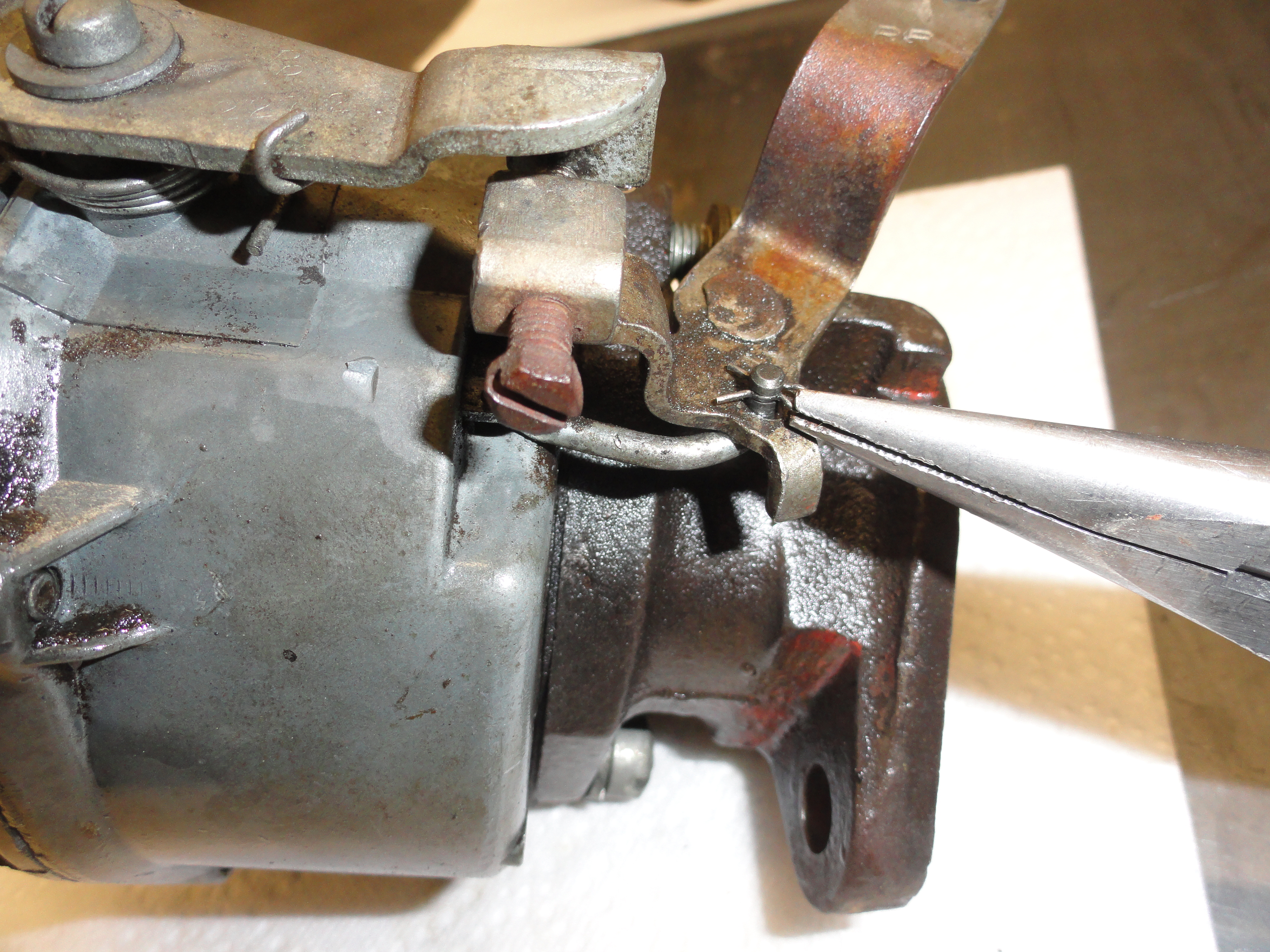

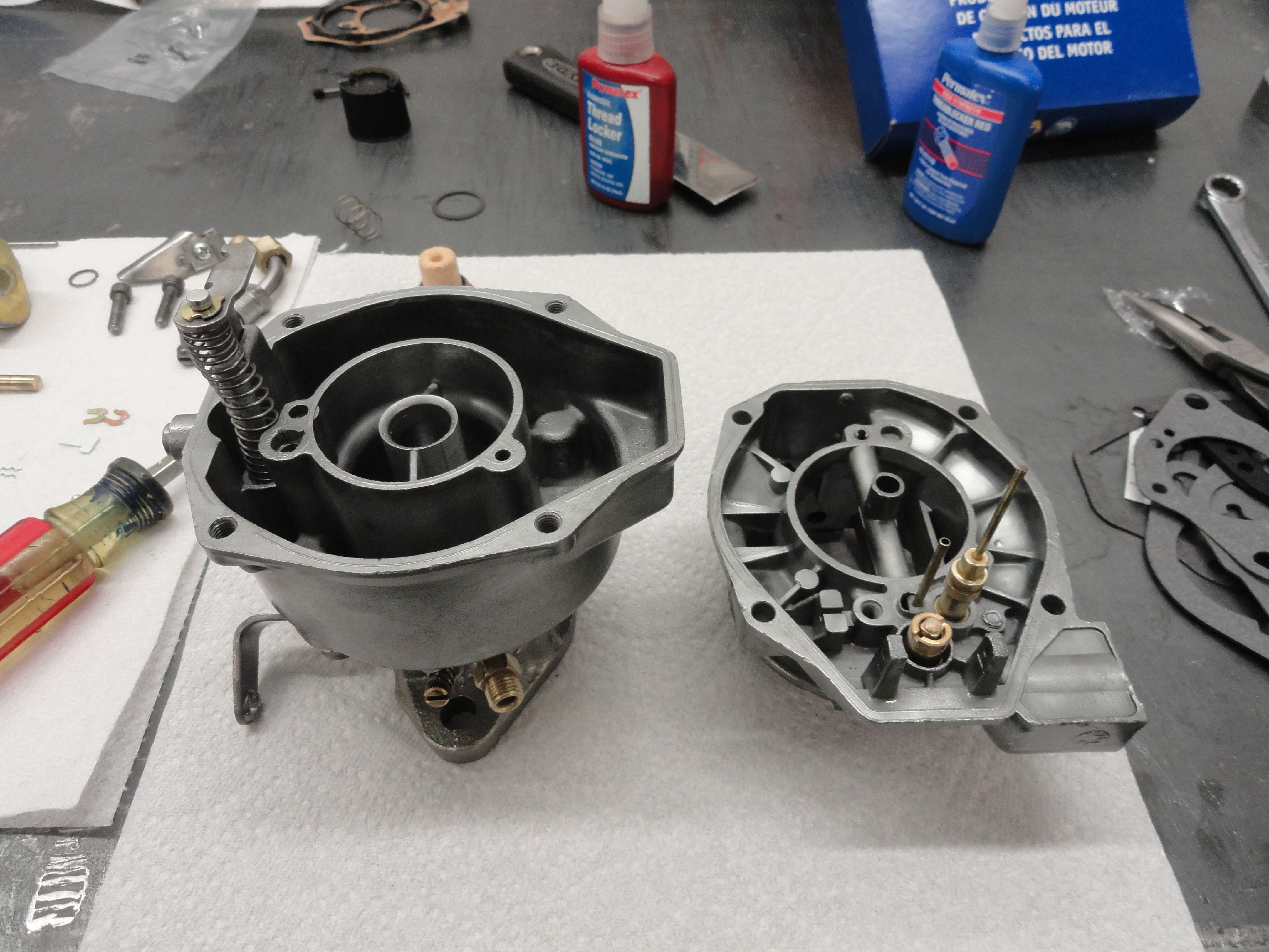
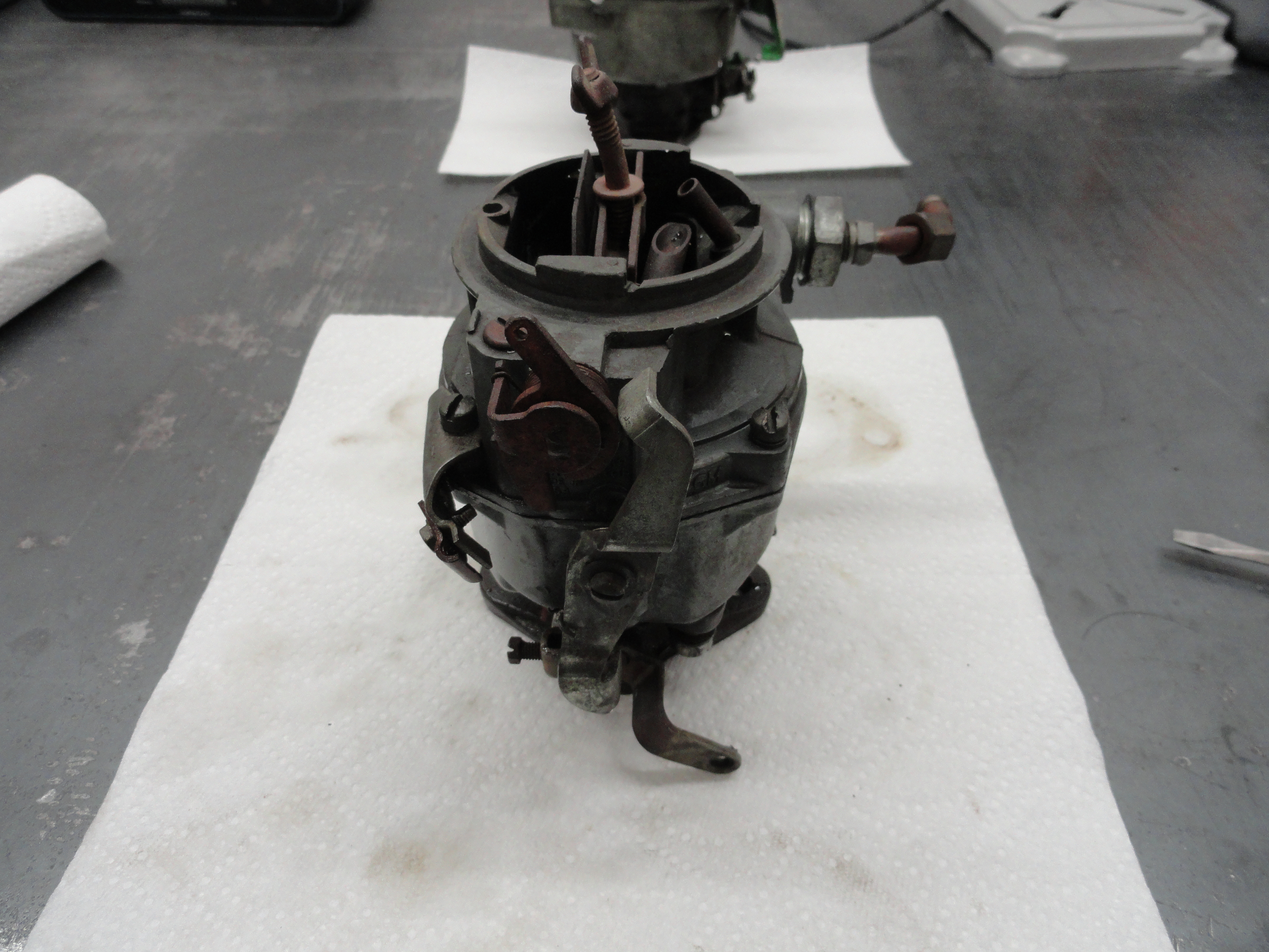
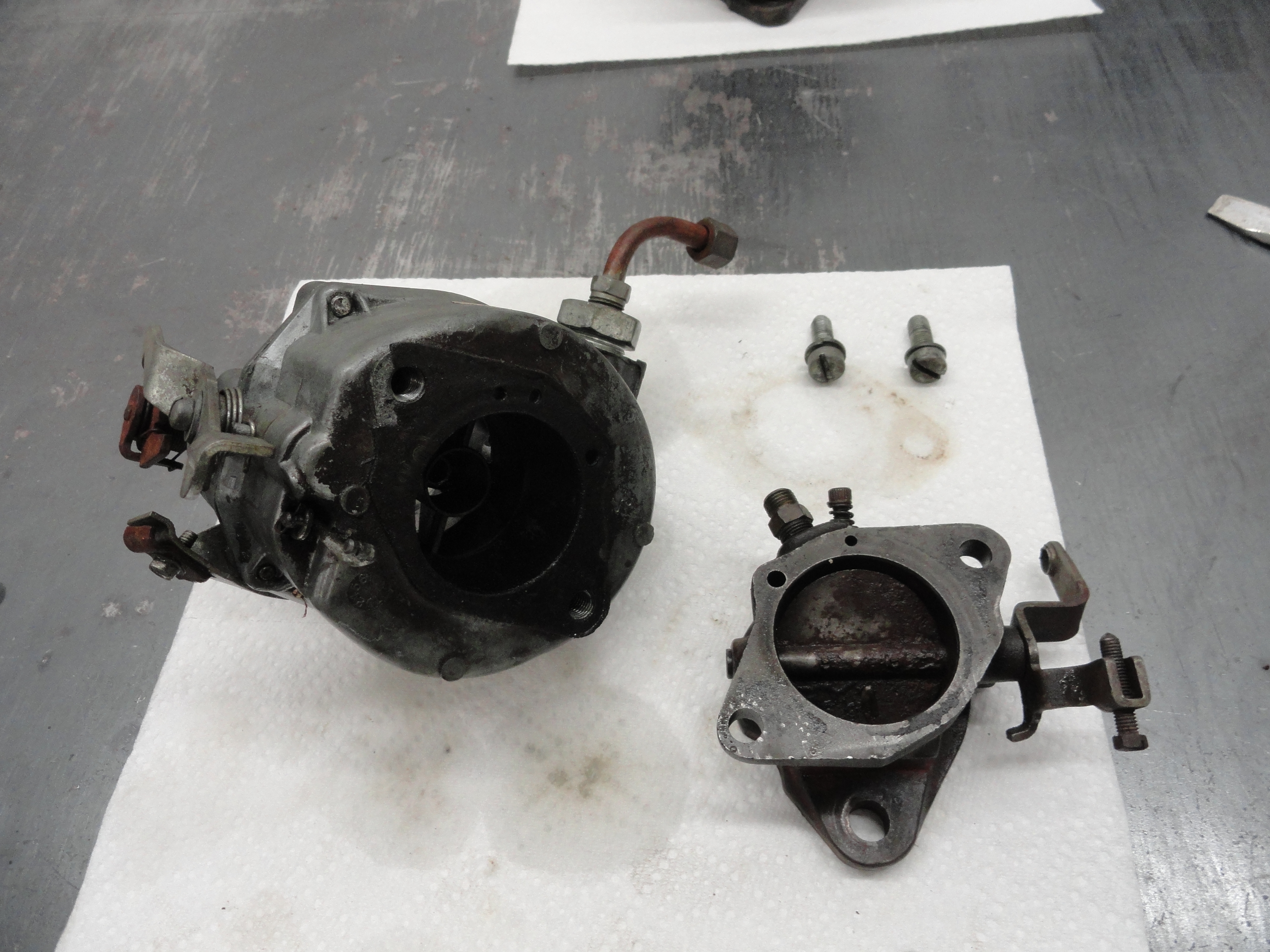
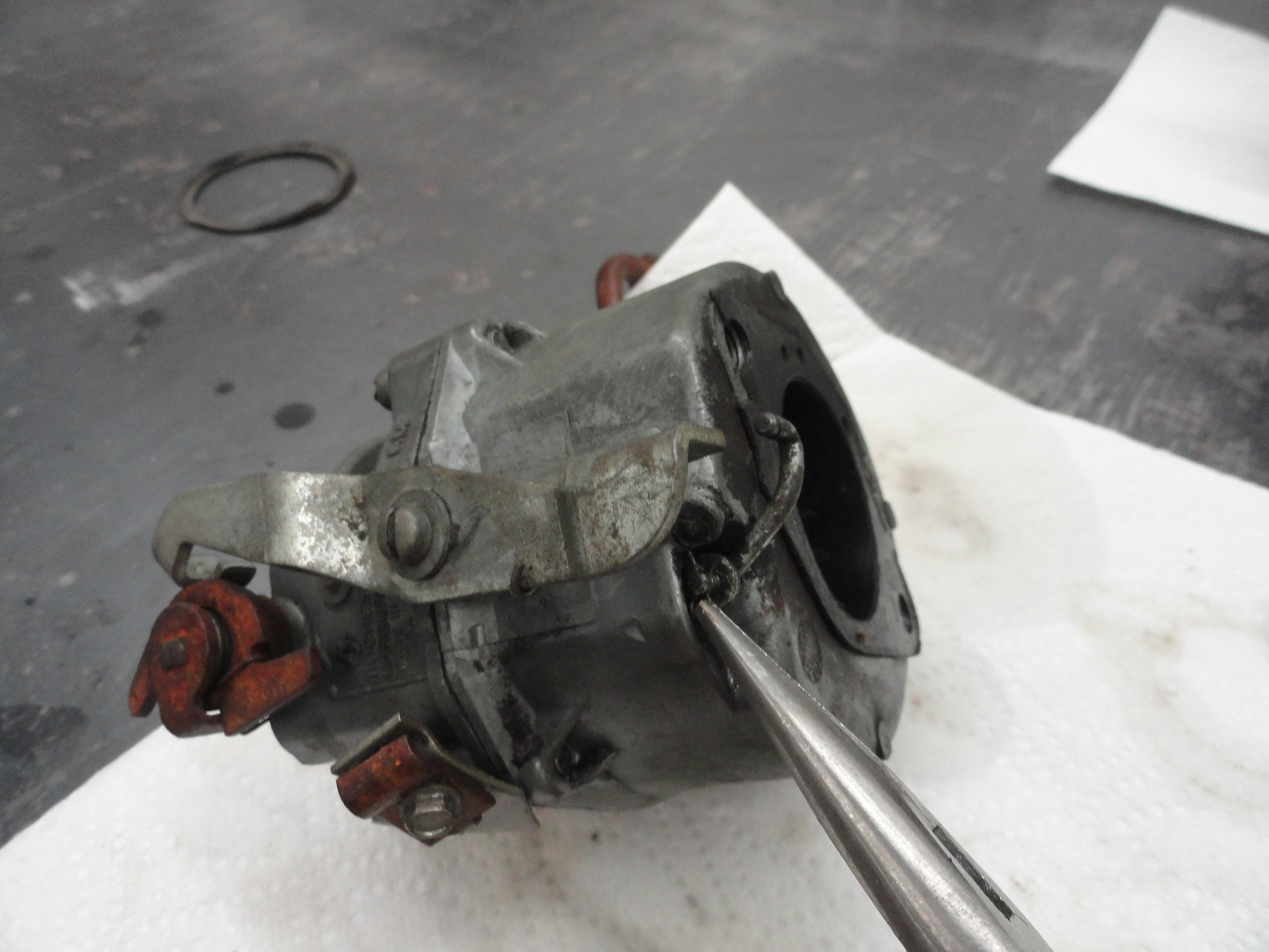
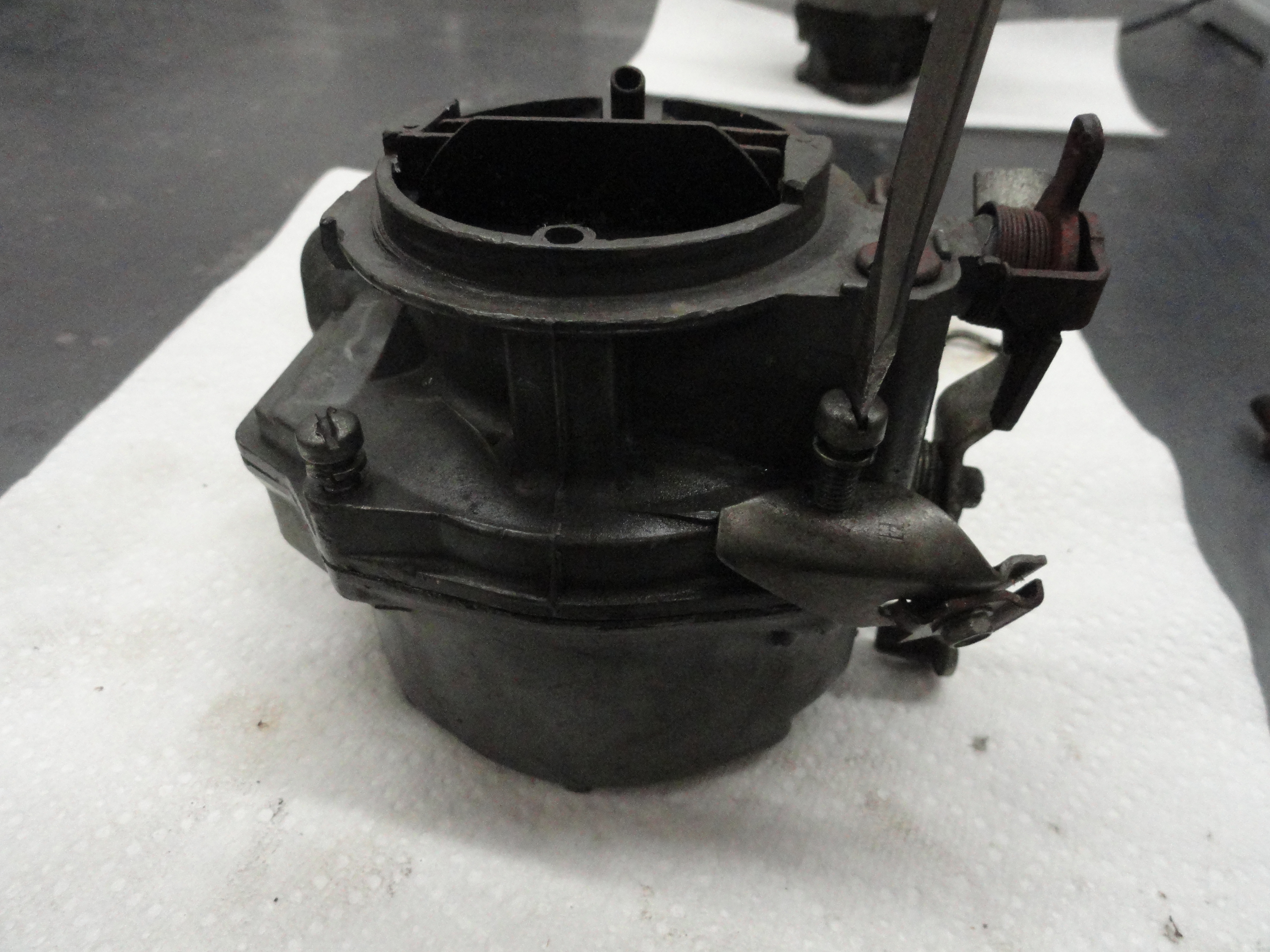
Clean the Carb with something that will make the surfaces very clean. Carb Cleaner or Engine Degreaser is good. I used my 3 gal. parts washer with Kerosene. Further cleaning will be necessary once we get it all apart. These pics are start to finish. Start by removing the bottom of the Carb. To do this, using a needle nose pliers, pull the clips from that small linkage (shown) and remove the linkage keeping careful track of all parts and where they go. With that linkage removed, you can now remove the bottom by removing the two large screws. Now, lets remove the top. The top contains the float assembly so be very careful when pulling the two apart. The 4 screws holding the top on are all that is needed, however, notice where the throttle and choke bracket is located on one of the corners. Carefully lay the top cover upside down on the table. There are several items protruding up from the top, but one of them will remain even when everything is apart. You need to protect that from damage while we clean and restore the inside of the carb. With the three main bodies separated, we can start taking the components out.

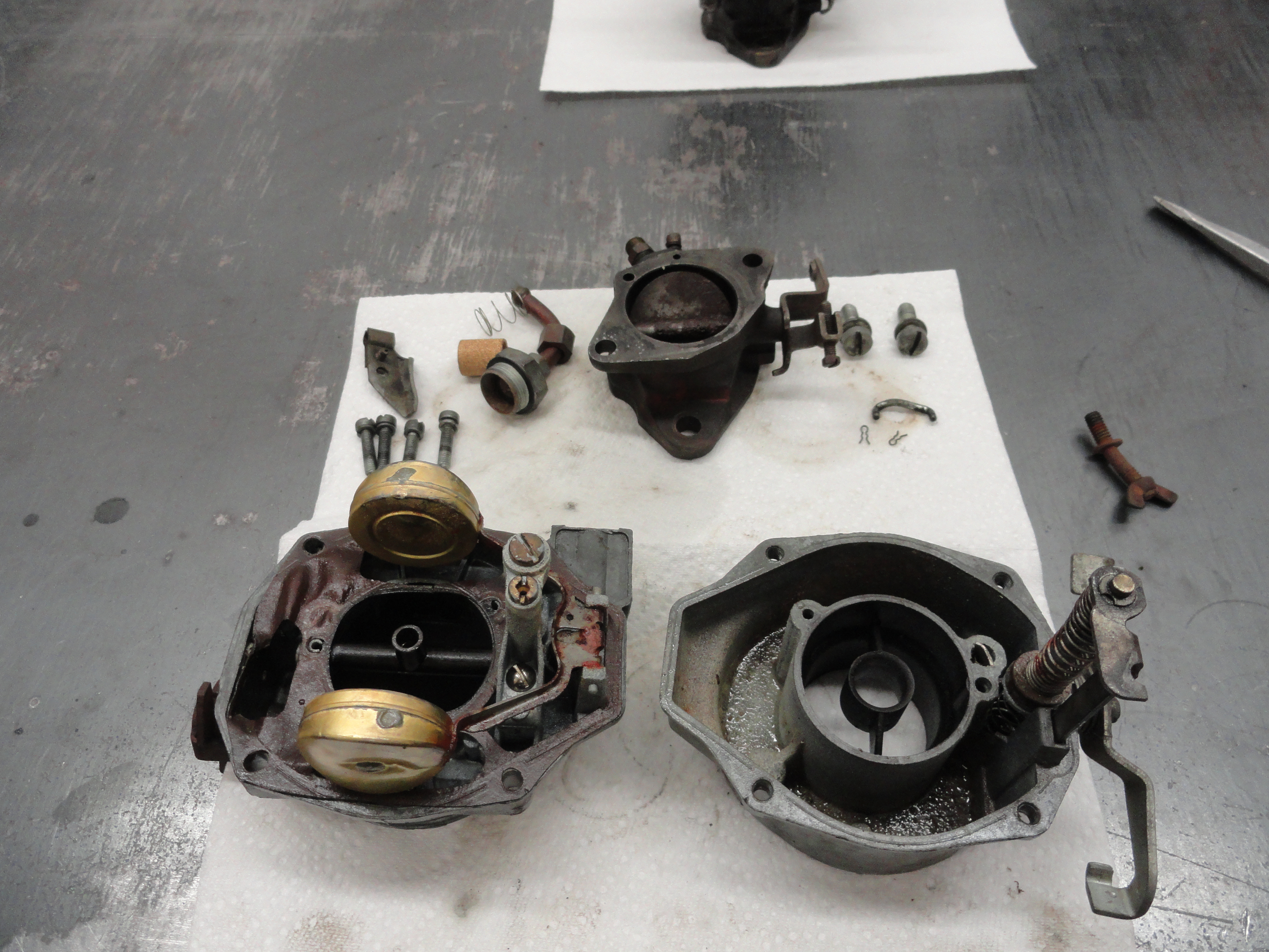
These Carbs are so old that it is very unlikely you will find one with the gold anodized plating intact. Out of the 5 in my inventory, none have any plating left on them. This means you will have a few alternatives.
I chose to go with leaving it the natural color of cast steel. I am not making this one for a show truck, so leaving it natural gives me the options
later if I choose to go another route.
We will begin by removing everything from the top cover. Start with the float assembly. The pin holding the float assembly should be
pretty loose and easily pull out of its holes. If you can't do it by hand, try not to mar it up but pull it out with needle nose pliers.
Just wiggle it carefully until it comes out. Keep track of the orientation of the float. Inspect for any visible damage. These floats are still
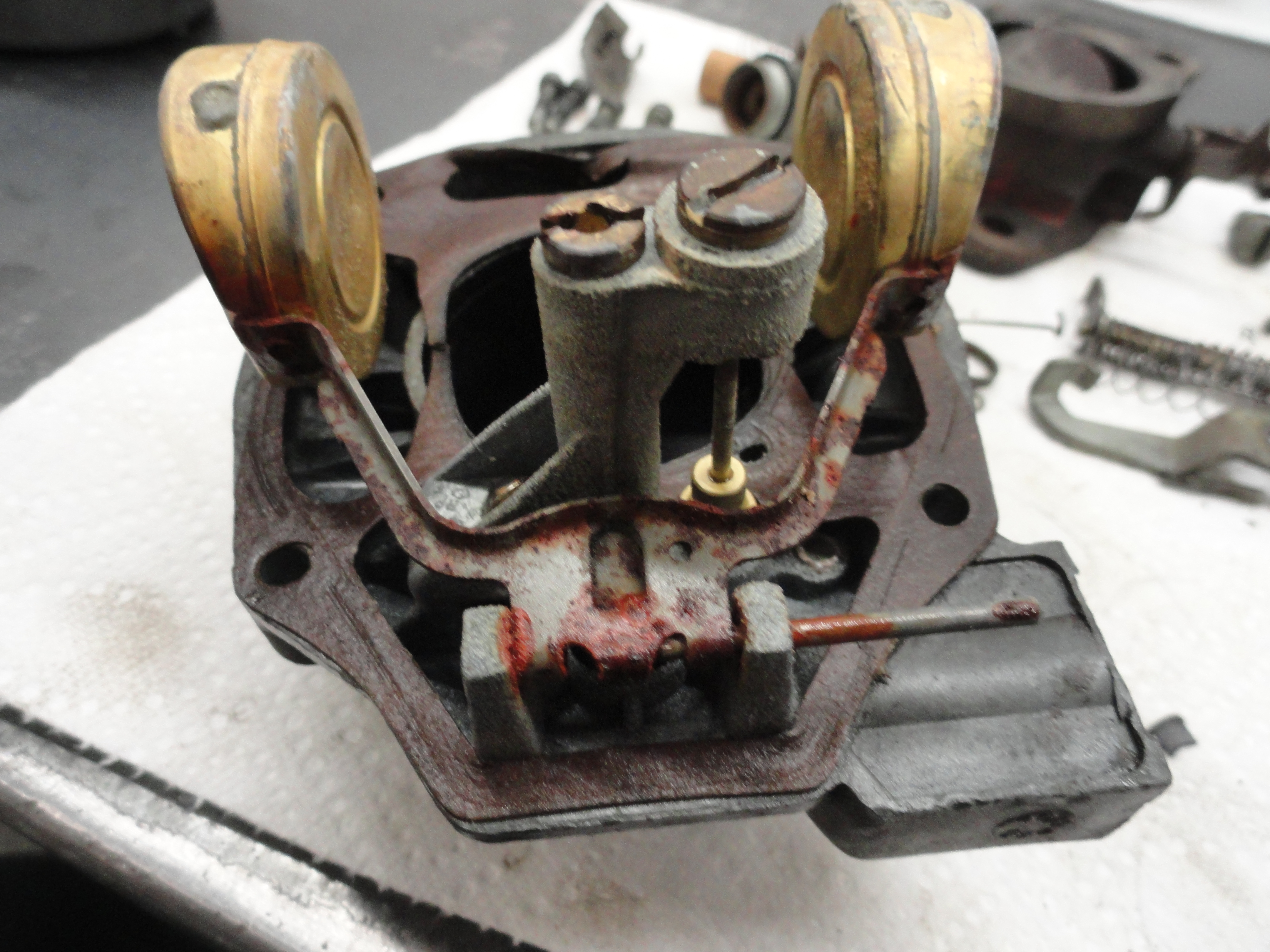
available as of this writing so if you feel the float has sprung a leak, or just to be precautionary, order a new one. Remove the Jet Assembly, which
is that brass carrier that has the slots on both sides of it for a wide screwdriver. Pull out the Jet, then the carrier. Remove the Power Piston
Tower. The top brass screw needs to be removed first. The smallest check ball is located under this screw (not the aluminum one thats in your carb
kit), so be careful not to lose anything.
Some models have a screen inside one of the holes in the tower. Just clean it really good and leave it in place. Next remove the Power Piston. This is usually stuck in my experience and hard to remove. Be VERY careful removing it however, since they are not available. Take your time and try every trick in the book to keep that Power Piston in tact and serviceable! This piston should move up and down very freely in order to do its job. The spring under the Power Piston is not available either, so be very careful removing both. The top of that power piston is important since the checkball sits on top of it and meters the gas intake.

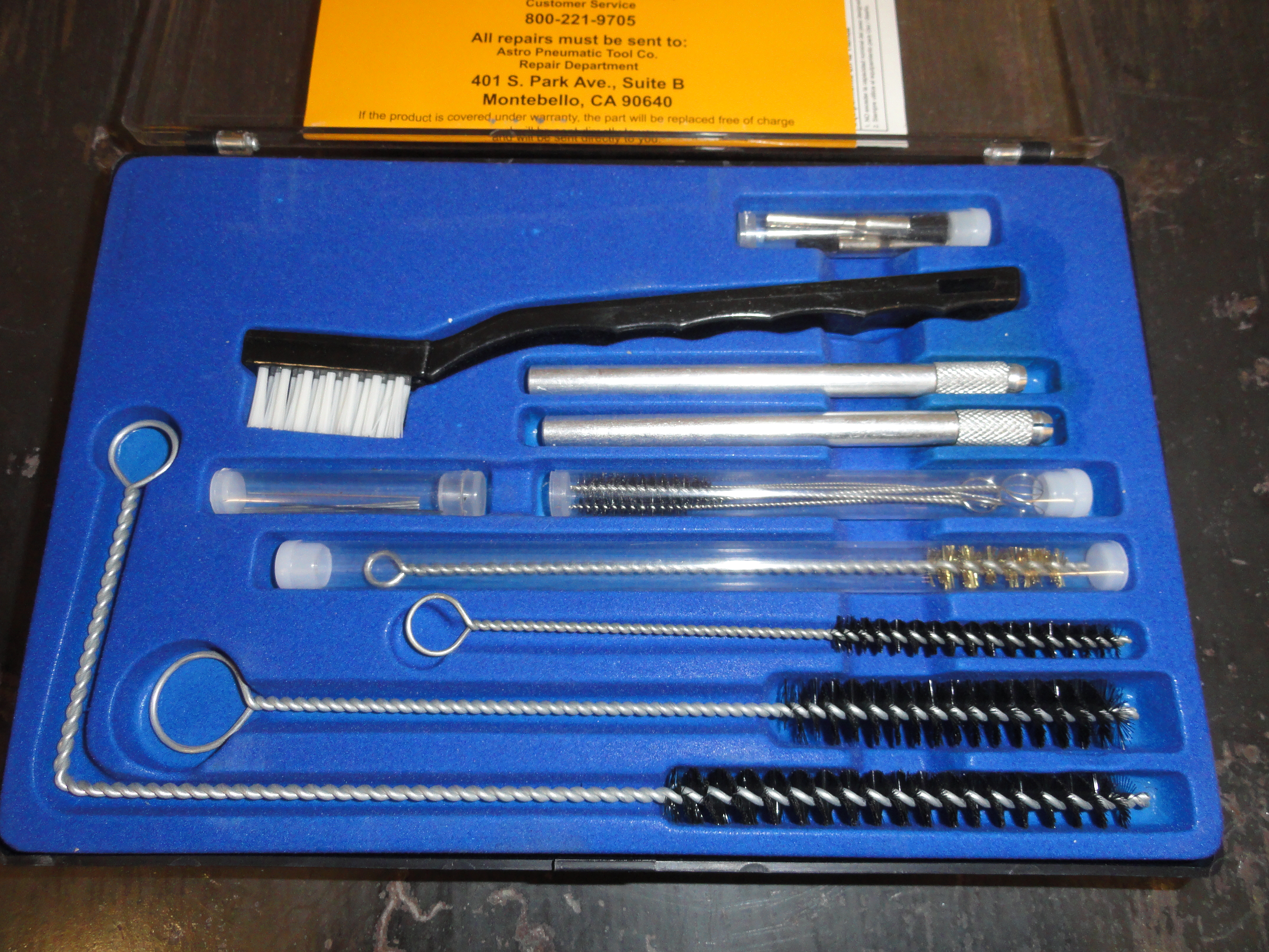
A very good thing to have in the internal cleaning process of all this is something you may have, but haven't thought of for Carburetors. It's the large size cleaning kit for HVLP Paint Guns. If you don't have one, take this opportunity to get one. In it, you will find things that are very important to properly rebuild a carb. For example, the kit has a tube of different size orifice cleaners (basically 2 inch pieces of strong wire of different diameters) as well as bottle brushes and other important cleaning aids. Turns out the holes in these carbs are very small and this kit just works perfect! Once the power piston tower, the piston and spring, jet assembly, etc, is removed, lets move on to removing the butterfly assemblies. Now, I CAUTION YOU! If these assemblies are working VERY freely and there is no end play or wobbling, I leave it up to you as to if you want to go to this trouble! Now that you have been warned, the butterfly on the Air Horn, or top of the Carb is held in by two screws that WILL strip out and cause you great pain and misery if you do not grind the ends off just a little first. Try it but gently and see if they break loose. If they don't, use your Dremel and grind the excess threads off the end of the screws. You will want to use Loctite Red to reassemble them once the screws are ground. Once ground, they should come out pretty easily. The very same is true for the lower butterfly valve. Check first, but if you think you might strip them, grind the ends off. It will save the screws and cause you from having to drill out and re-tap a very intricate assembly.
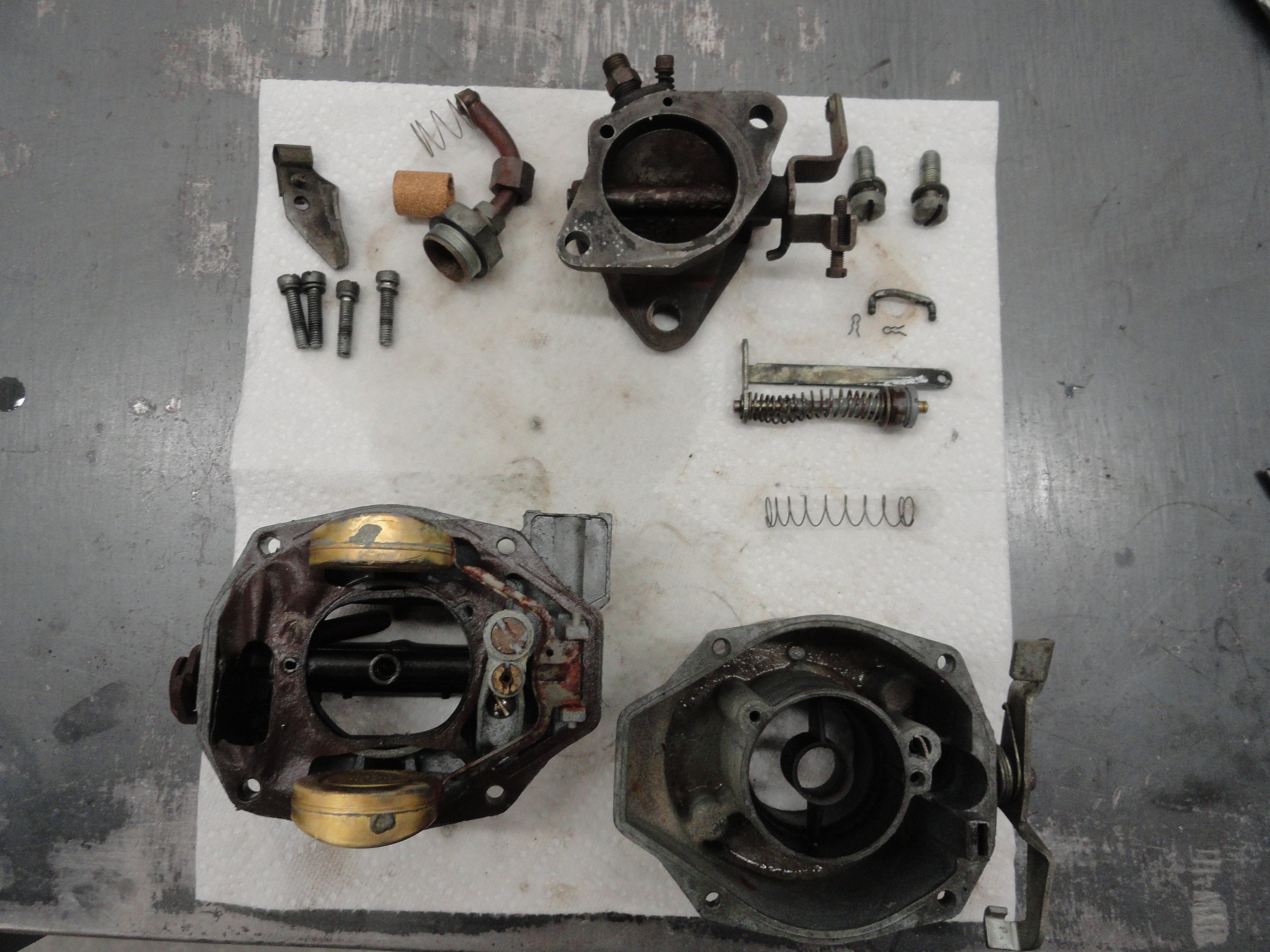
Now that you have totally removed all parts out of the Air Horn (top), let's move on to the Body. Remove that little T-Clip which holds another check ball. It's called the main discharge tube. A lot of times the checkball gets stuck and won't come out. Get it out anyway! It is the other STEEL larger checkball in your Carb kit. Remove the large plunger mechanism, with tower bracket and spring and place them aside. You need to keep everything, even if you see the carb kit has a new one. Why? Personal experience! So now that the body is completely stripped, let's get to the Base Assembly.
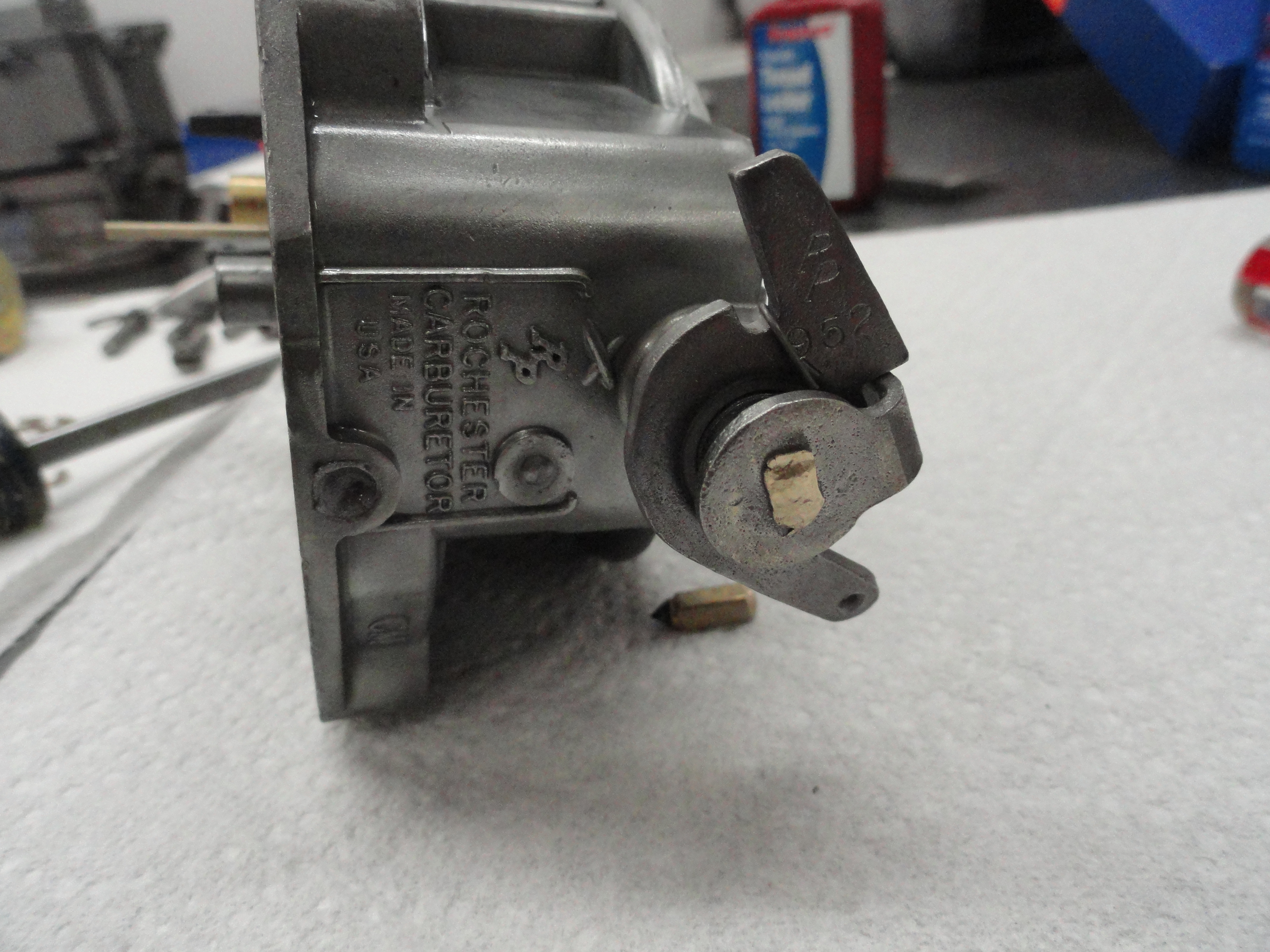
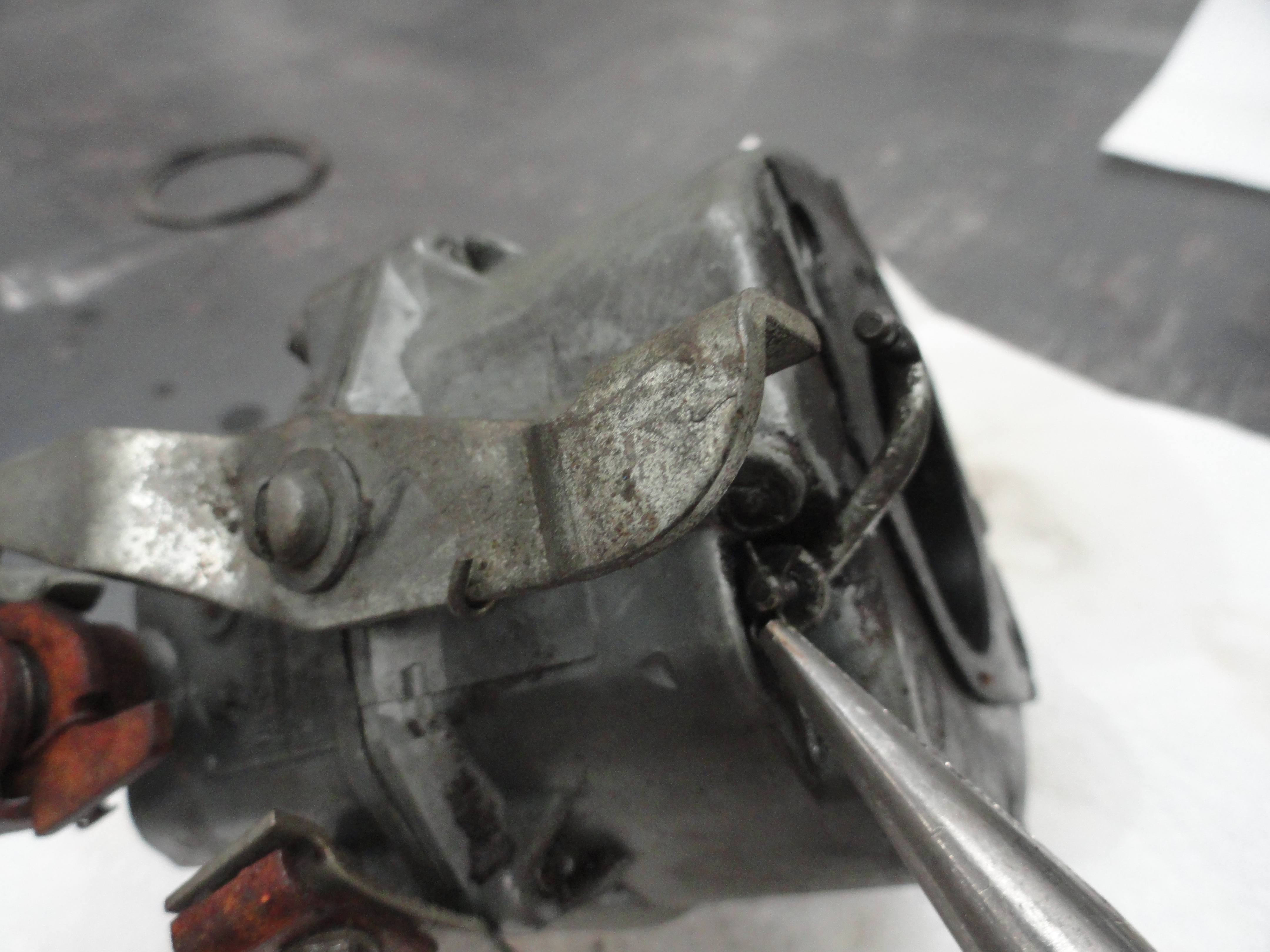
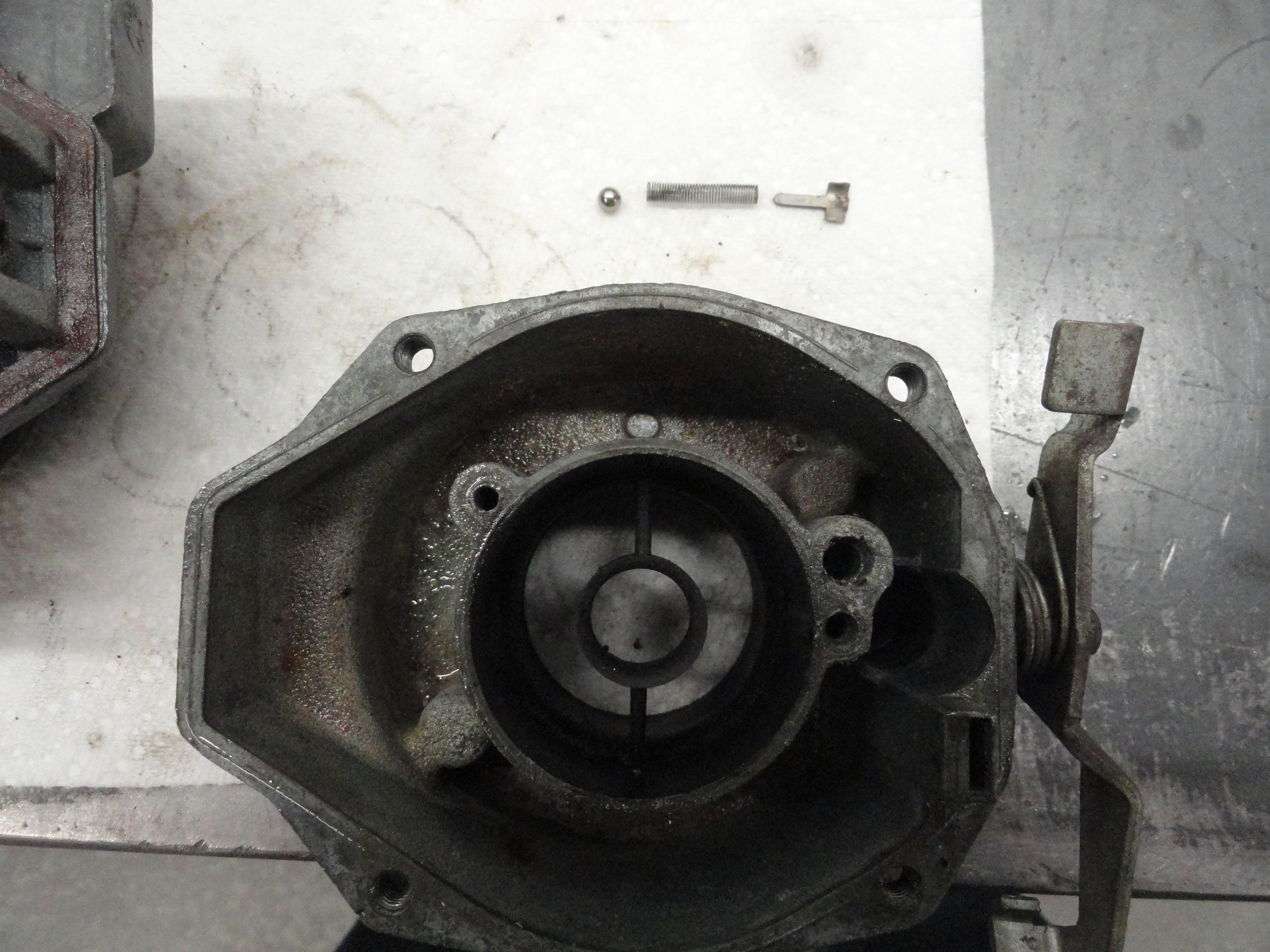
The Base Assembly is really the only part that is different for example between a 250 engine and a 235. It has to do with the spacing between the two mounting flange bolts. Never toss a Rochester B carb that has the wrong mounting bolt pattern. Thats ALL the problem is. Get the correct one and the rest of the carb is good. Remove the Brass idler screw with spring, and the vac advance fitting. If you chose to go the route of removing the bottom butterfly assembly, you should have a totally stripped base unit. The only reason for removing these butterfly assemblies is slop. Slop either side to side, or in and out. Sometimes a brass drift punch will move enough material to stop the slop where the steel and brass converge. If you are doing this, I assume you fully understand the workings of a shaft and its supporting mechanisms and how to proceed. Ideally, NO slop on any plane. You also want to assess if it's tight because of rust or dirt buildup, or if it's really nice and tight! This is why I usually opt to remove both butterfly assemblies.


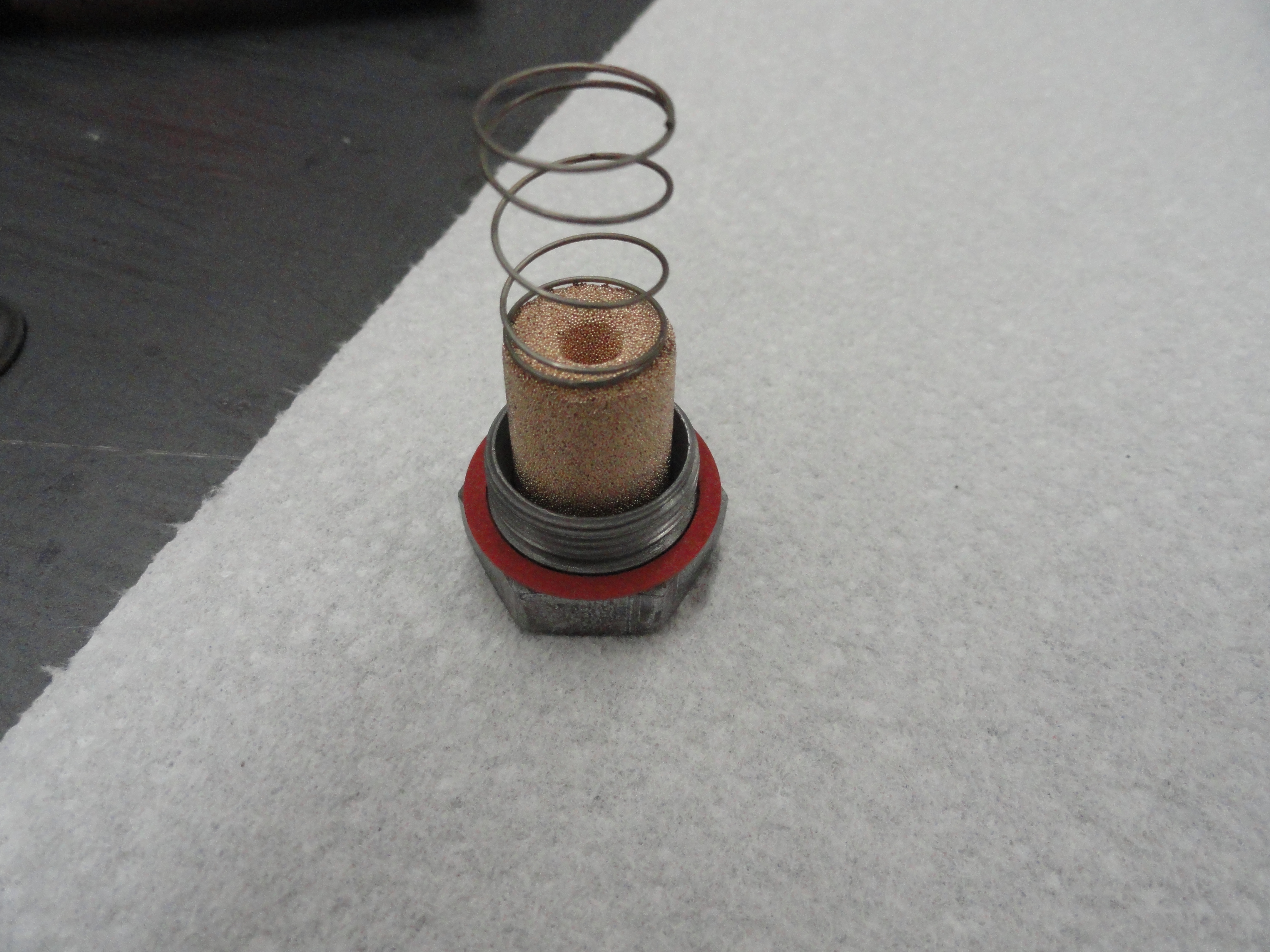
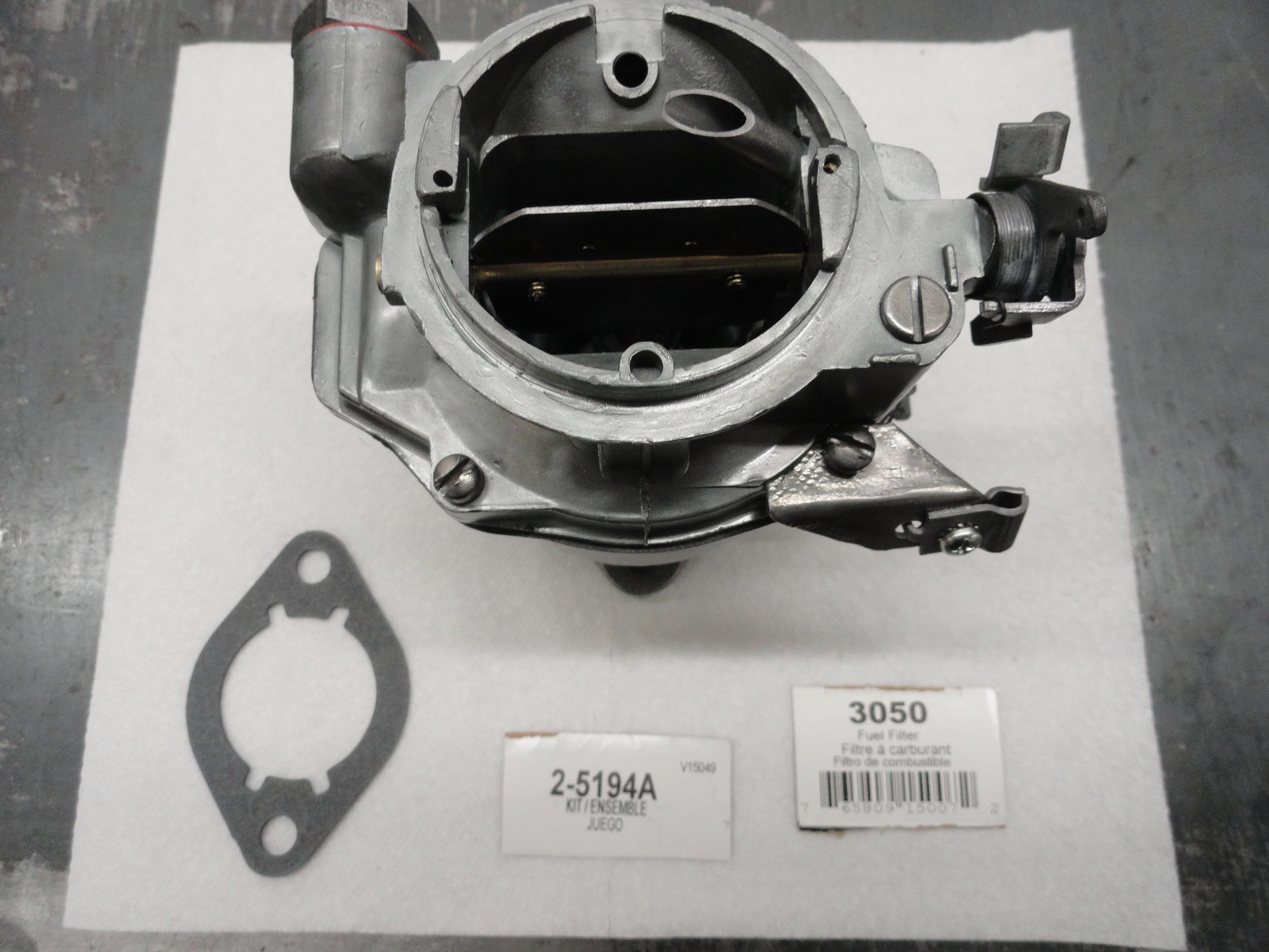
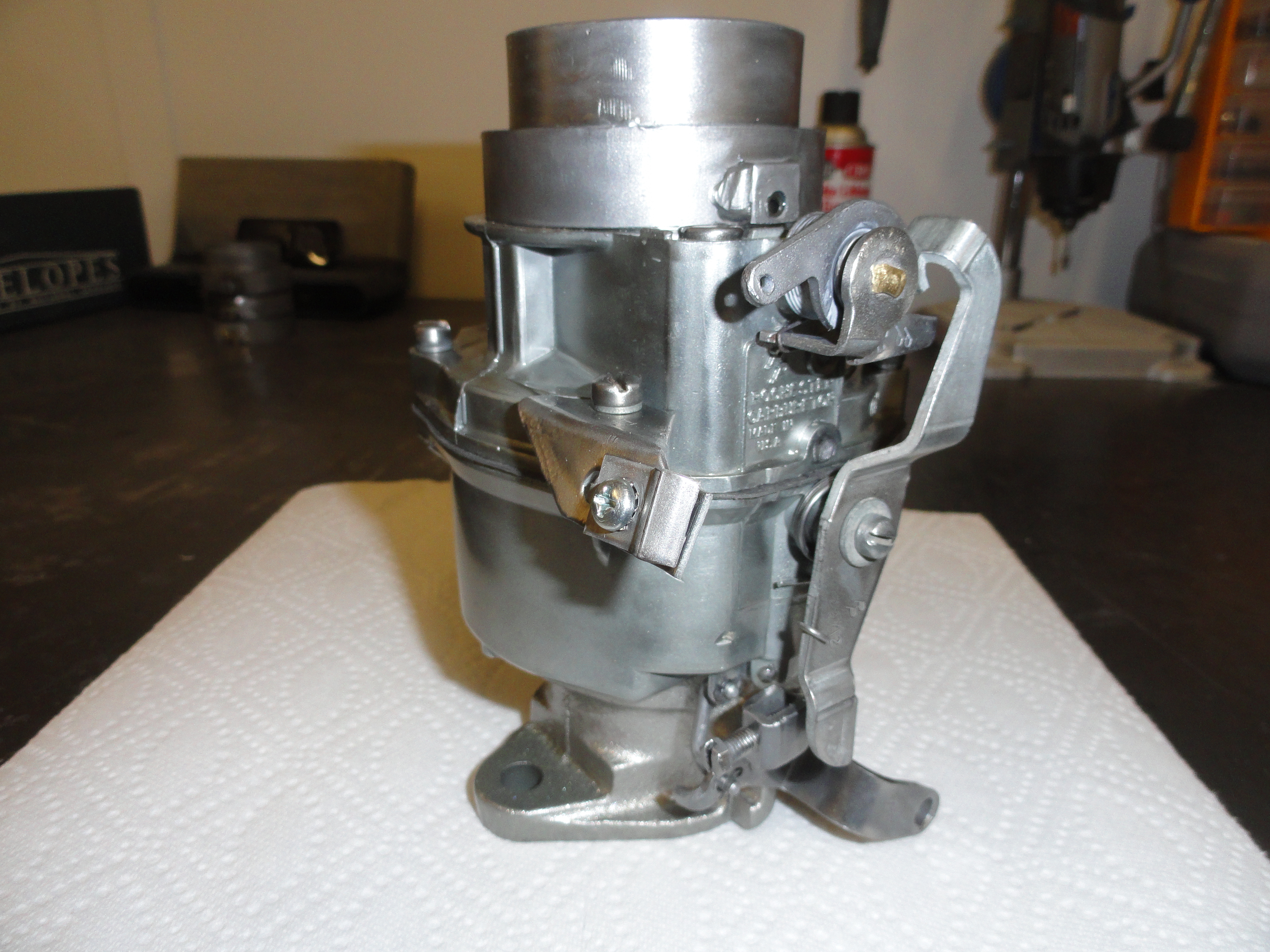
At this point, every little thing is taken totally apart. Now, let's talk a little about purchasing the carb kit. If you were one of the 30% of the lucky ones who actually have a metal tag affixed to the top of the carb on one of the bolts, you WIN! All you have to do is tell the NAPA, or parts person at your auto parts store the number, and he can look it up and give you the correct kit. For the rest of us, personally, I think 30% was a gift on my part, we have to do some investigation. Sometimes, on the bottom of the Body assembly, that same number is stamped on the underside. There goes about another 20% of you. The rest of us, get a carb kit from the year model of the truck it came out of with no number. This is an in-exact science, but thanks to someone thinking a tin foil TAG was a good idea, we are stuck with it. Chances are, ordering a Carb kit for a 1959 235 (in this case) will probably get you home. I pay about $30 for Carb Kits these days for this vintage. They come with pretty much everything I need, but if you need other parts, I would Google Mikes Carbs. He stocks a lot of hard to find parts and could very well save the day! Thanks Mike! The Carb Rebuild Kit I purchased for this one is NAPA part number 2-5194A (V15049). The Fuel Filter is NAPA part number 3050.

So it's all apart and now it's CLEANING TIME! Woohoo! Every little thing needs to be super cleaned. From the photos I am sure the first thing that comes to your mind is that Deve is crazy. That's the idea.. because going overboard just insures your carb will actually do its thing when the time comes. The carb in this case had lots of green corrosion. This is what happens when gold anodized parts lose their anodization and steel/anodized meets. It's a mess, but Chevy didn't anticipate you would be trying to mess up their business model by fixing trucks that are 60 years old! Clean all surfaces, no matter how hard they are to get to. It's your precious CARB! I used blasting, Dremel with fine wire brushes, bench grinder wire brush, sandpaper, some very fine files, whatever it takes for you to get to what you see in these pictures. Granted, I am a clean freak, but you read about all of that earlier, so nothing new. This is the SAME orientation taken AGAIN after doing the cleaning. One day of cleaning is a small price to pay for not just helping you guys out, but to get my carb to work perfectly on this Venerable 1959 235 Rebuild.
The hardest part of this was remembering how the springs go back on. You don't want to install the butterfly's for example and have something backwards. Especially since you put Loctite Red on the threads. These are the only 4 screws I recommend Loctite Red on. Reason is because you ground then down to get them out, ruining their self locking nature. Remember, to remove Loctite Red you have to heat the screws up to 500 degrees! Please don't get this far and make a mistake!

Start with the Carb's base. Install the Idler screw (the one with the pointy tip and spring). Screw it all the way in, then back it out one and a half turns. This is a good place to start and recommended in the Carb kits instructions. Install the Vac Advance fitting as well. Get it nice and tight. If you removed the butterfly, now is the time to put it back on. Choose orientation carefully. If you aren't sure which way it goes, set it in, then look to see if everything is very tight with it just sitting there and are the screw locations in the correct spot. Turn it around and check again. You will find that it is settled in only one way. The screws faces are viewable from the underside of the carb if that helps. Once you are very sure you have the assembly right, use Red Loctite to hold them in place. Remember, before they had expanding nubs on the ends of the screws to keep them from getting sucked down into your precious engine. Now, choose the gasket that mates up to the float bowl. Use the correct one. You will see where the old one used to be so don't plug any holes with the wrong gasket. Once it's in place, go ahead and put the two screws back in that hold it on the float bowl. Tighten securely. I personally do not put anything on these gaskets. They work just fine without adding sealers or something that could contaminate your fuel system.
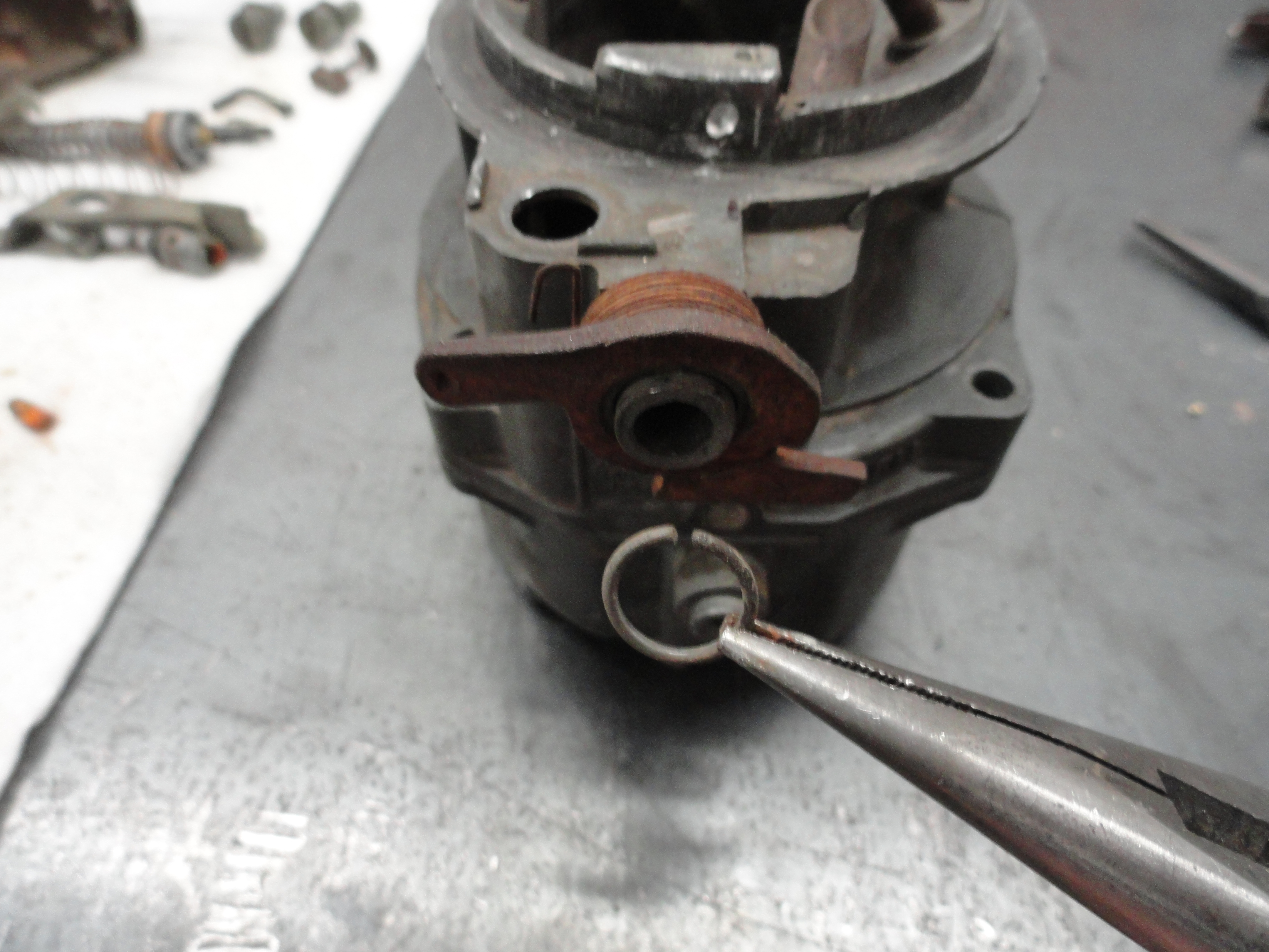
It's important to go back and look at some of the disassembly photos to make sure you are assembling correctly. Now let's look at the Float Bowl or body of the carb. We want to put the Accelerator Pump back where it belongs. Only there is one in the Kit, so let's use the new parts. You will need the spring that goes under the pump, put that in first. Then the heavy spring goes around the pump itself. Push all of that down in the hole and put the pump bracket in its slot in the body, and push them both down until you can get one of those U-shaped keepers in its slot to lock it all down. I found this much easier to do on the carb as opposed to wrestling with it on the table. Don't forget the lighter spring goes in first. Squeeze the U-shaped locker to keep it from coming off. Now that the assembly is put together, from the outside, re-attach that little linkage from the bottom of the Accelerator Pump assembly to the butterfly assembly on the base. It points IN with the dogleg facing OUT. Use the smallest clips in the new Kit to secure. You should now have an accelerator linkage that springs back by itself.

Setting the float bowl with base in front of you, install the first check ball. It goes into the larger hole near the accelerator pump where the T shaped keeper goes. Large (not the aluminum one) checkball, then the new very small spring (looks like the spring off an ink pen), then the T which goes down into the spring and then pushes flush with the hole. That's all there is to the float bowl.
Turn the Air Horn (top) upside down on the table. There is one tube sticking up that was not removed during the cleaning. In front of that is where we want to install the Needle Seat which is that part that has the two slots for the bigger screwdriver. The Carb Kit has a new one with a gasket. Be sure to install the new gasket, then turn the new seat into place. Tighten securely. We do not want any leaks there. Careful not to bend anything! Put the new Needle aside for now. Find the correct gasket in the new kit and fit it in now. Make sure your chosen gasket isn't plugging any holes or in the way of anything. Fitting the gasket in now is the correct way to do this.
To install the Power Piston, put the spring inside of it, and set it in and check for movement. Does it move freely? You want it to be very smooth. Also, the thin end of the piston needs to be straight. If it isn't, it may not push the checkball out of the way properly. Set the spring and then the Power Piston in place, then install the Tower. The power piston goes in the small hole at the end. Once you are certain the piston moves freely in the hole by turning it and watching the movement, set the smallest steel checkball in that hole. Then from the Carb Kit, get that little spring that has tapered ends on it, and place it in the brass cap. Once you are sure the power piston, the checkball and the spring/cap are lined up, tighten the cap securely. Lastly, for this part, install the Metering Jet. It's the brass piece that has a number on the top rim. Tighten securely.
Install the float assembly by first dropping the Needle Valve in its place, then properly orienting the Float Assembly and sliding the keeper bar across and centering it. We need to check a few measurements at this stage. Make sure you have it in correctly. The little tab in the very center protrudes downwards. Once the float is sitting flat with the top upside down so we can see where it is resting, there should be 1-9/32" from the very top of the float pontoon to the gasket. They supply a measuring square with the Carb Kit. These are important measurements, so be sure you understand what you are reading. To change that measurement, very delicately bend that center tab in or out so when it sits on the needle valve, you get the proper measurement. Next, turn the assembly upside down and let the floats dangle. Now measure from the gasket to the top of the float pontoon and you should have exactly 1-3/4". If not, there is another tab that is bent for that in the center of the assembly. Once you have both sides perfect, you are done. If there is a difference in the two floats, that would be a very delicate bend on just one side. In any case, you want to be sure the floats are not interfering with the gasket or anything else. I took less pictures of the final assembly because I was looking at the disassembly pictures to figure it out. You have everything you need to do this right in either the pictures with the text here, or in the out-takes below. Now that you have everything adjusted, carefully mate the Air Horn with the Float Bowl taking care not to bend or bind anything. Put two of the four screws in to secure the top adjacent to each other for now.
The upper butterfly assembly is next. This is something that takes some concentration because you don't want to get the spring in backwards, or forget the keeper on the end of the shaft, or get the wafer in backwards. To do this right, lay out all the parts as they will go in. First the spring, then the wafer. Hold them up to the hole as shown and then lock them down with the round keeper you removed earlier. You will need to 'wind' the spring one revolution so that everything springs together properly. Of course, wind in the direction the spring is wound in, and don't bend it. All of the pictures are in very high resolution so you can see clearly how to do it. When the shaft is proper, the butterfly shaft will have indentions where the screws go readily visible. Slide the butterfly in between the shaft slots and just put the screws back in, but wait on the Loctite until you are certain they are in right.
If you want to use this carb with an older style air filter assembly, you want to drill out the pins that are holding the nut bridge assembly and remove that. It just restricts air flow for your purposes, so no need to have it in there. You can always replace it later should you need this awesome carb for something that requires it. With the butterfly assembly in place and rotating very smooth, we need to install the lever assembly to the side of the carb. It also has a spring that needs to be installed correctly. This is the bridge between the lower butterfly and the upper one. Install according to the pictures and it will turn out fine.
I have to say, this is a pretty neat mechanical device when you think about it. Beautiful in its simplicity. Yet it is very critical all parts are assembled correctly. This section of the article would not be possible if it weren't for a few things that really helped me out. Most of the credit for my learning all of this goes to Mike at Mikes Carburetor Parts. Mike put a nice How-To Video on YouTube. Just Google Rochester B YouTube. It's 45 minutes long and he does a much better job explaining all of this. Then if that wasn't enough, he put the Rochester B service manual on his site to download for free! Also, remember that Carb Kit you purchased? Well, it has lots of great information in the instruction page. From parts breakdown to adjustment information, don't dismiss its value. Here you will find the overflow pics on this Carb Rebuild.
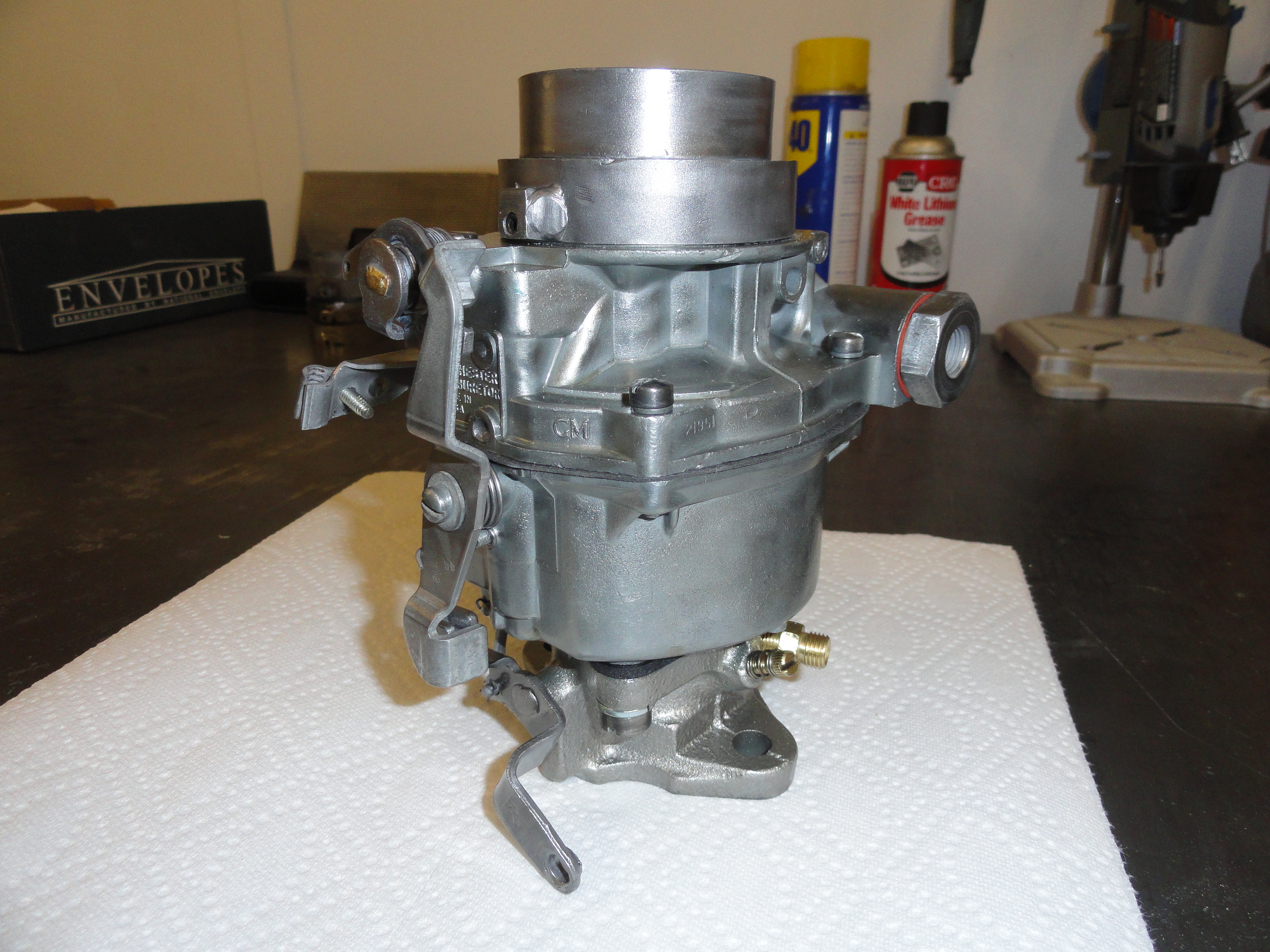
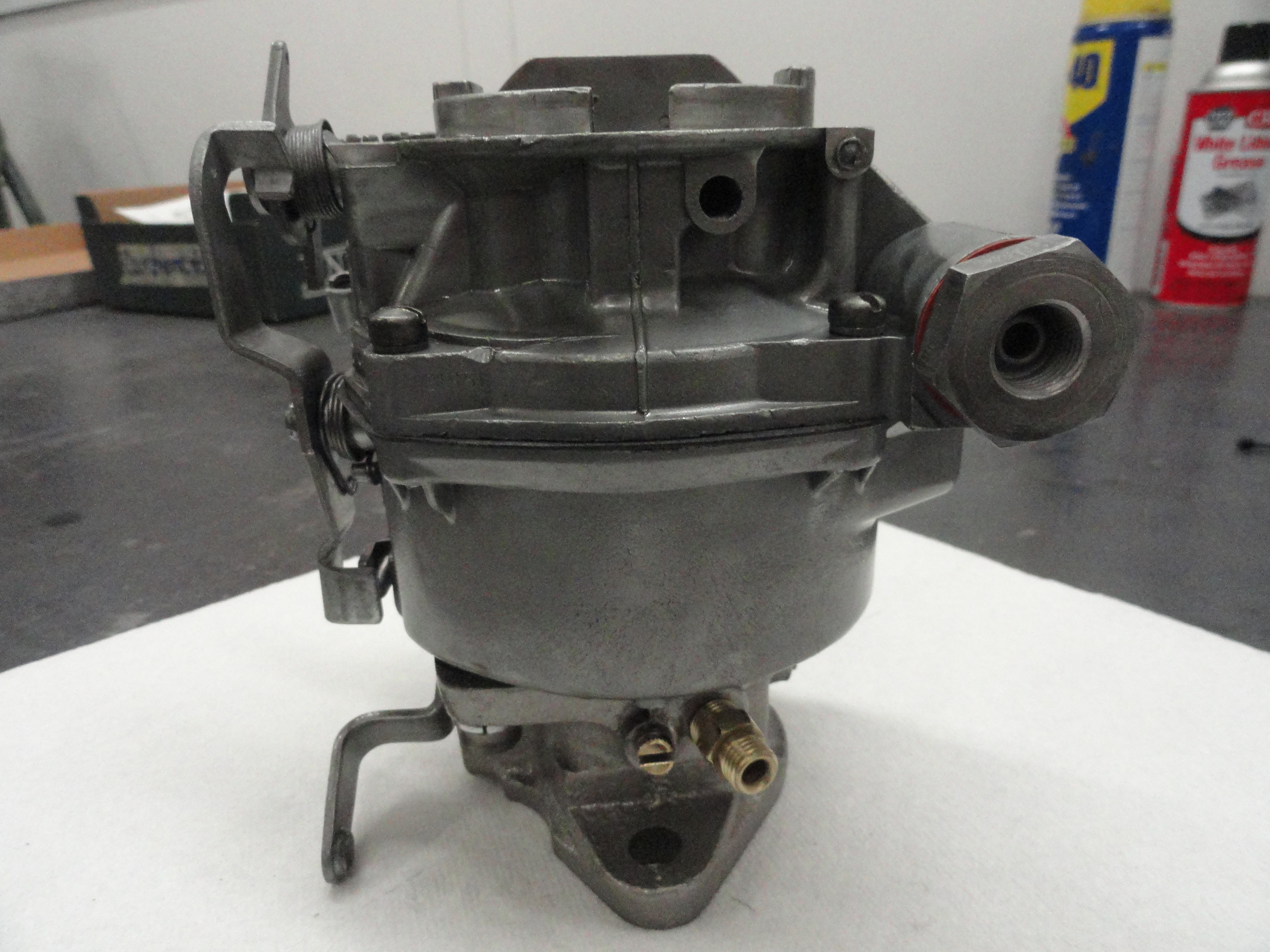
The finished Carb is really fitting for this project. In this process, I chose not to change out the Float Assembly. Even though it's only about $15 for a new
one, I will try this one first, then if it's bad, I can change it easily since I didn't slather a bunch of gasket sealer all over it. You can get rebuild entire
Rochester B Carbs for about $180 with the core, but what would be the fun in that? If you haven't had the opportunity, check out Mike's Carbs web site. I don't
put links in these How-To articles any more than I have to since they change so often but go to the trouble because Mike has parts for these Carbs that you may
need. Things are changing out there folks... 60 year old parts are getting harder to find. We need to have the proper respect for vintage parts and understand
they are not an unlimited commodity. On to the next assembly. Hope you are enjoying the journey! If you have questions, email me anytime!
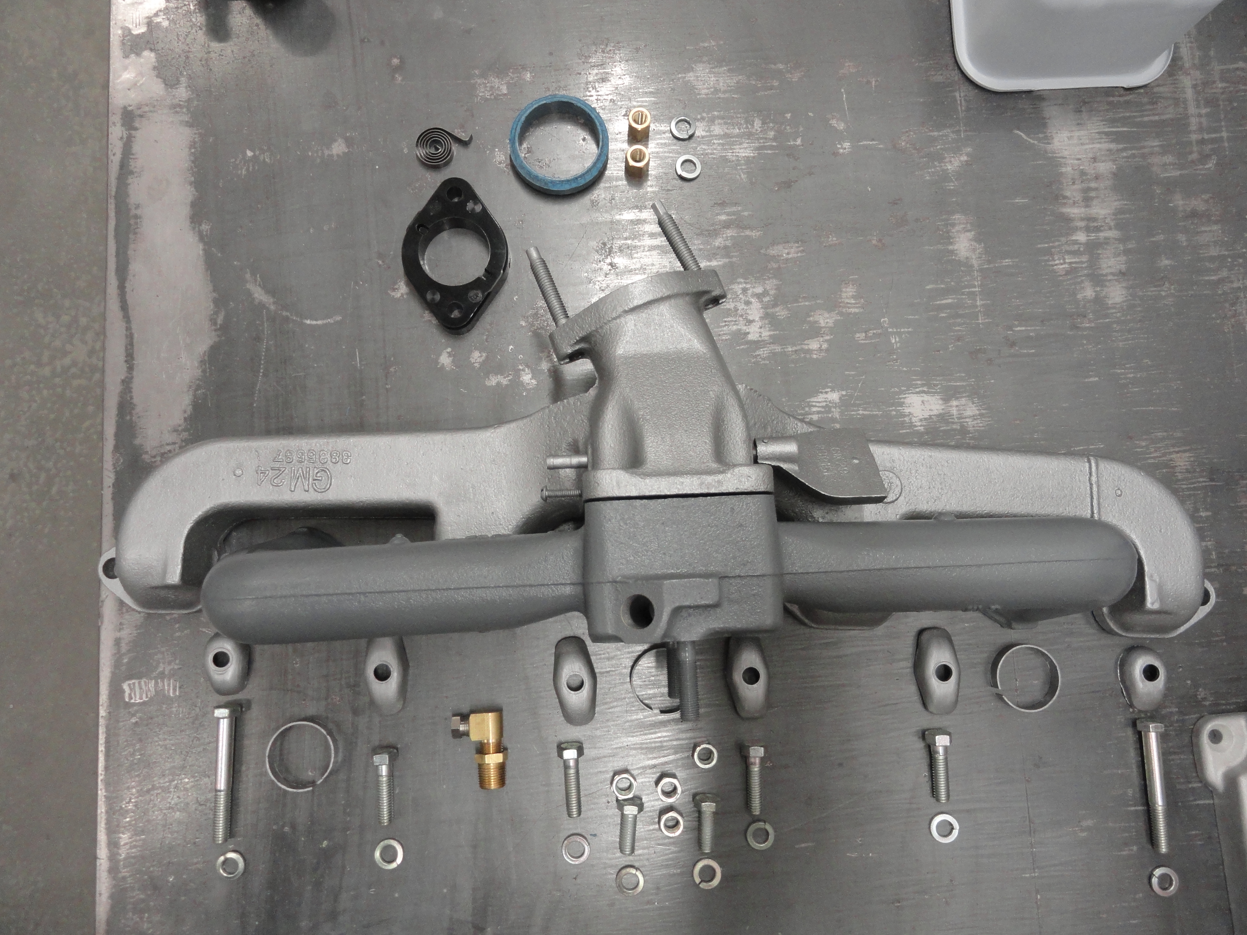
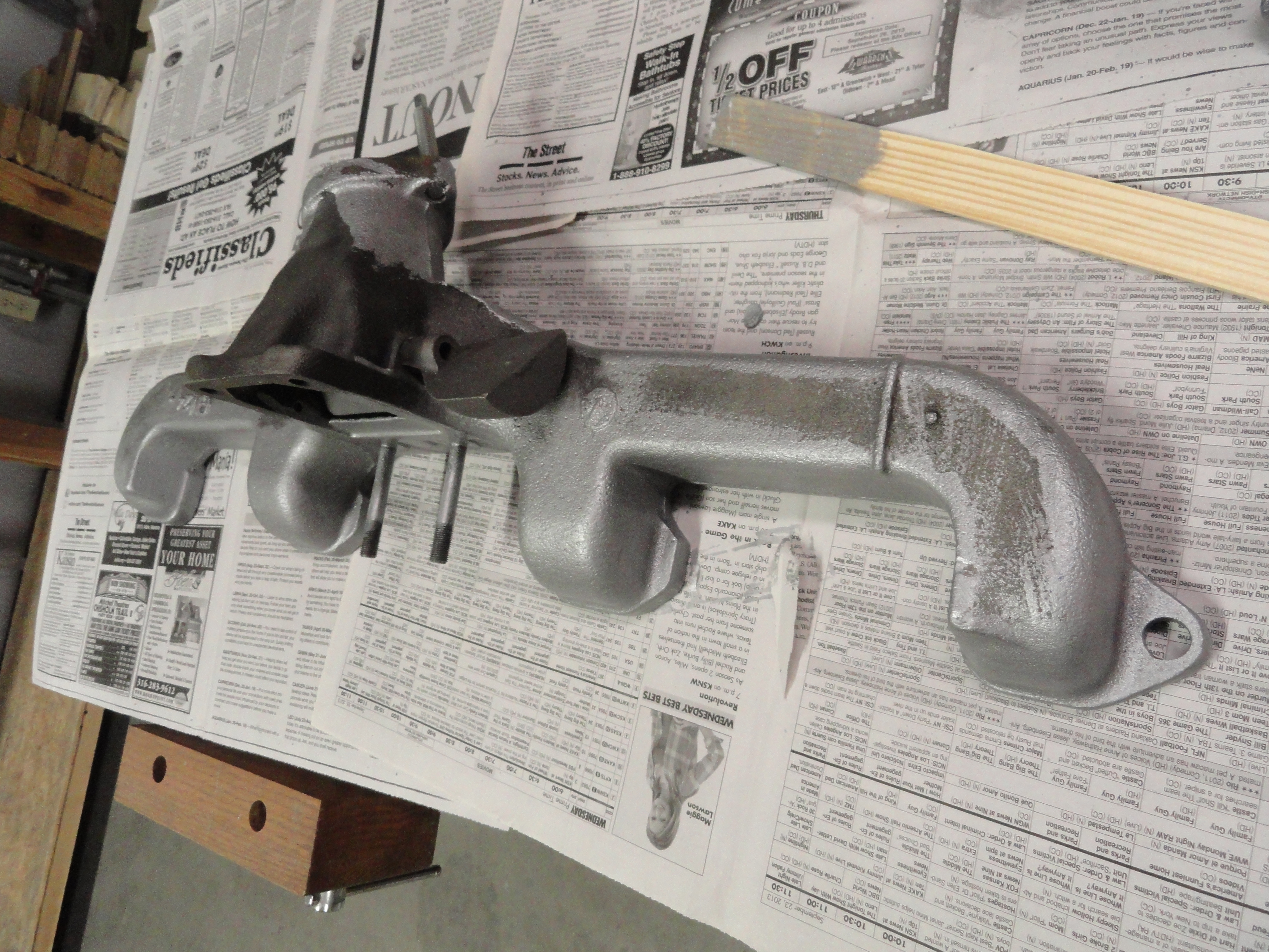
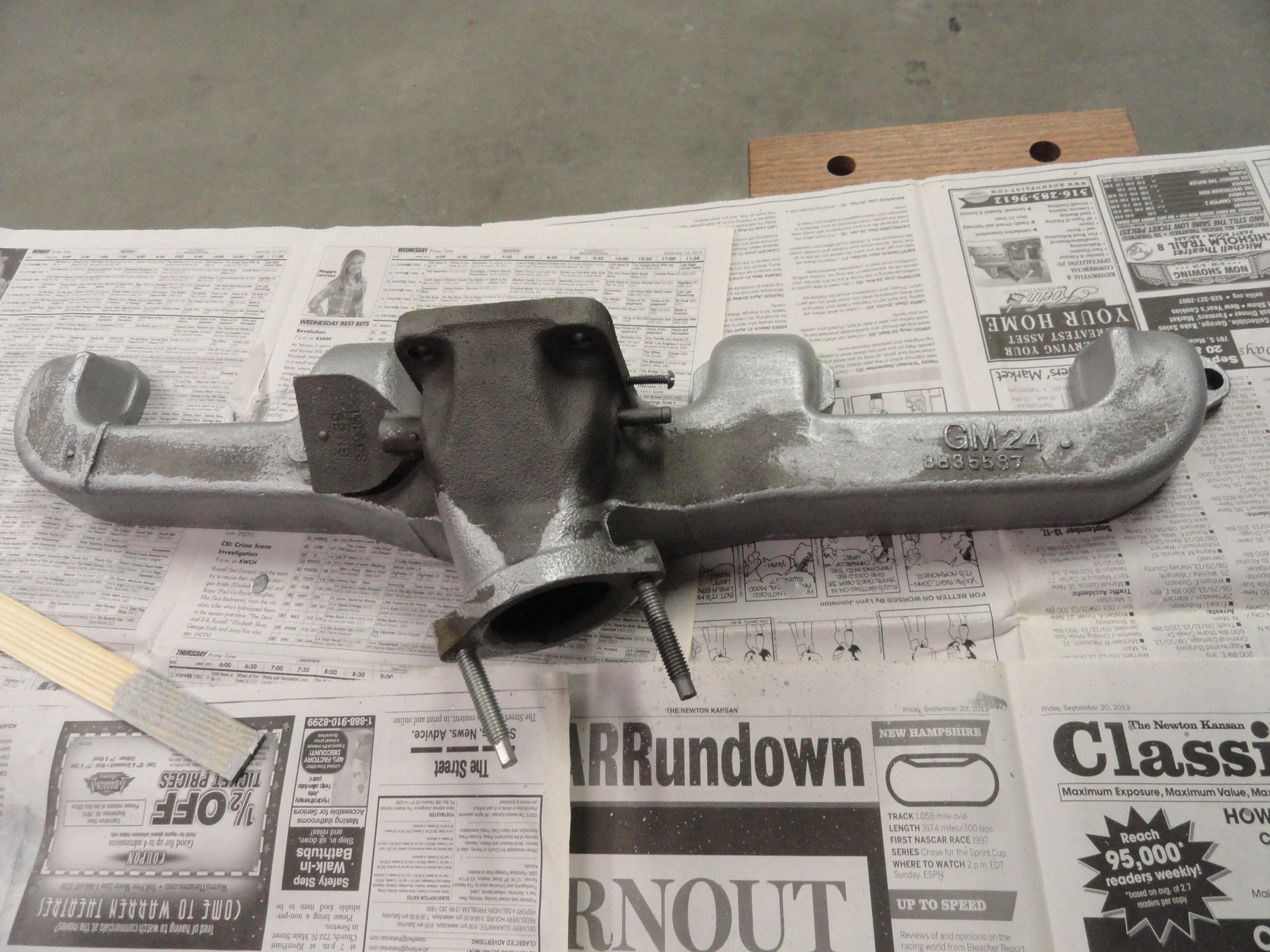
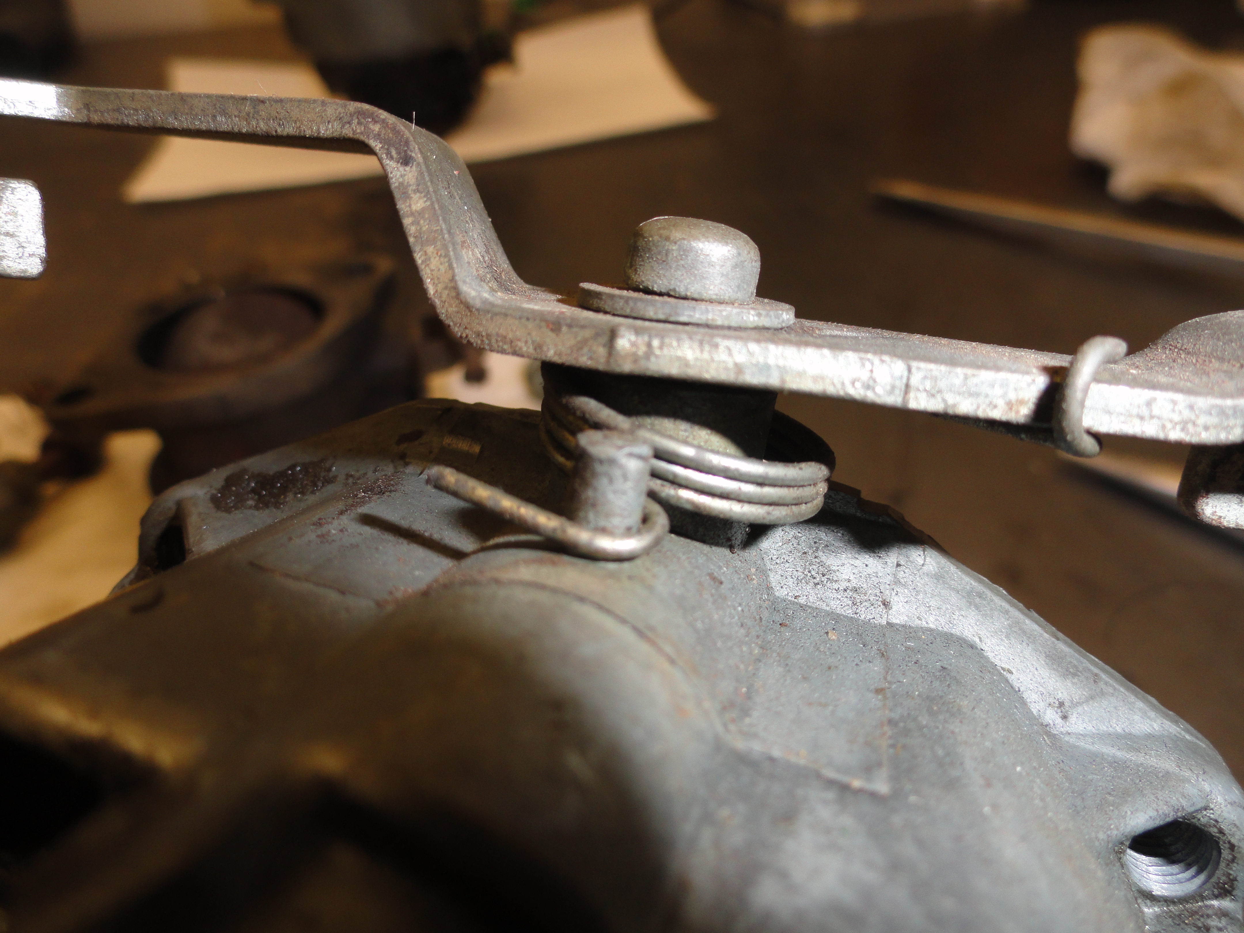
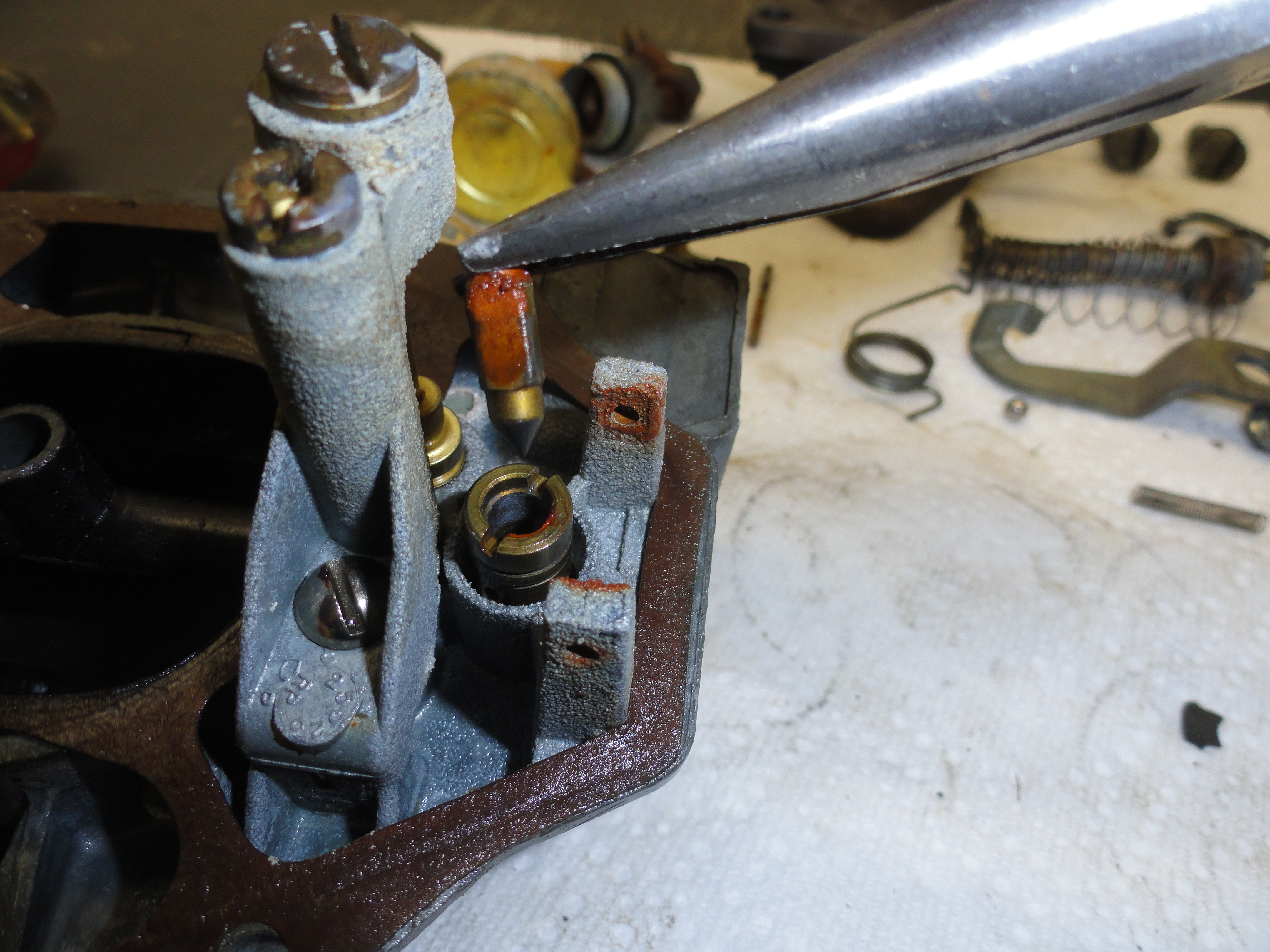
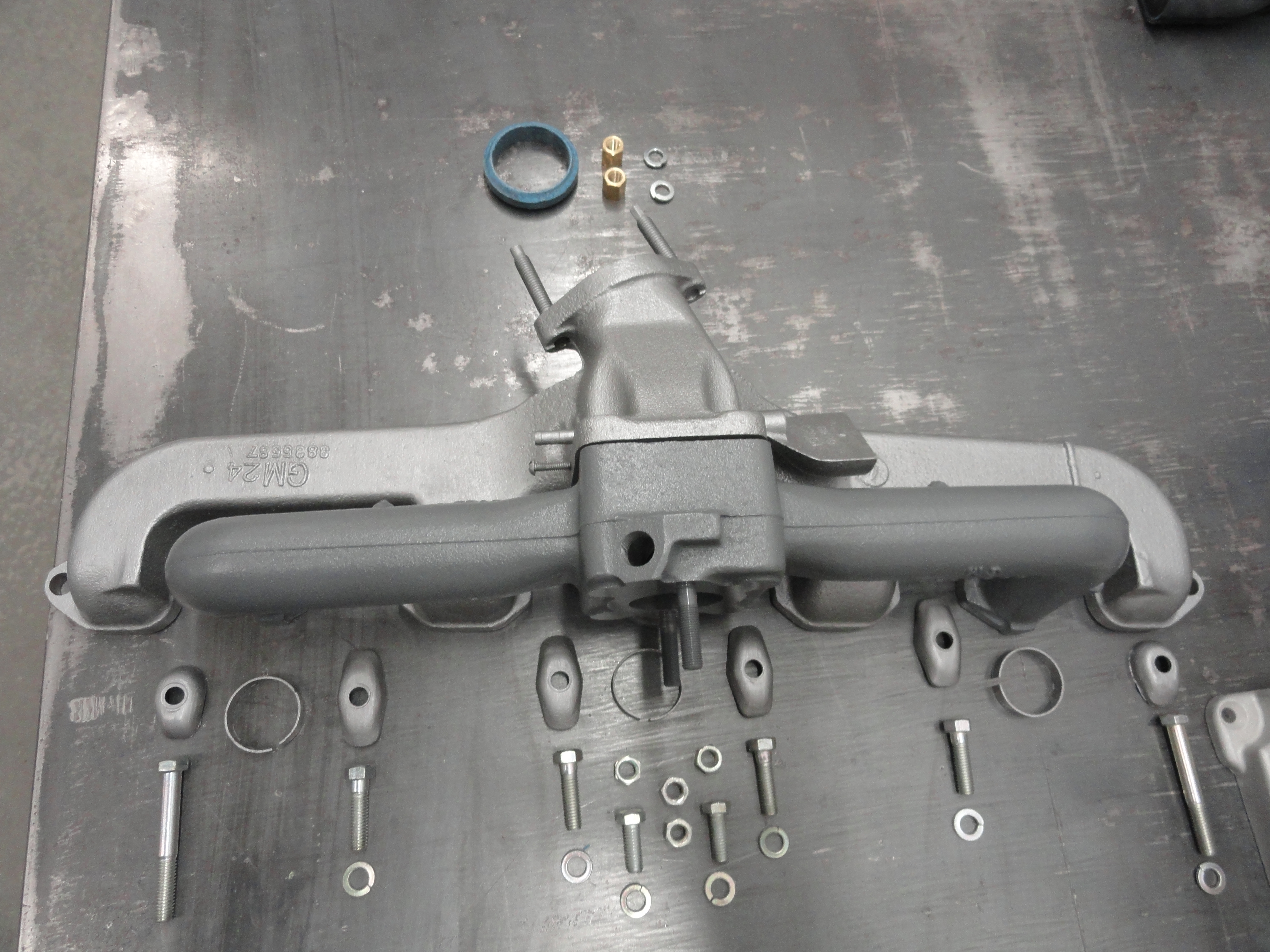
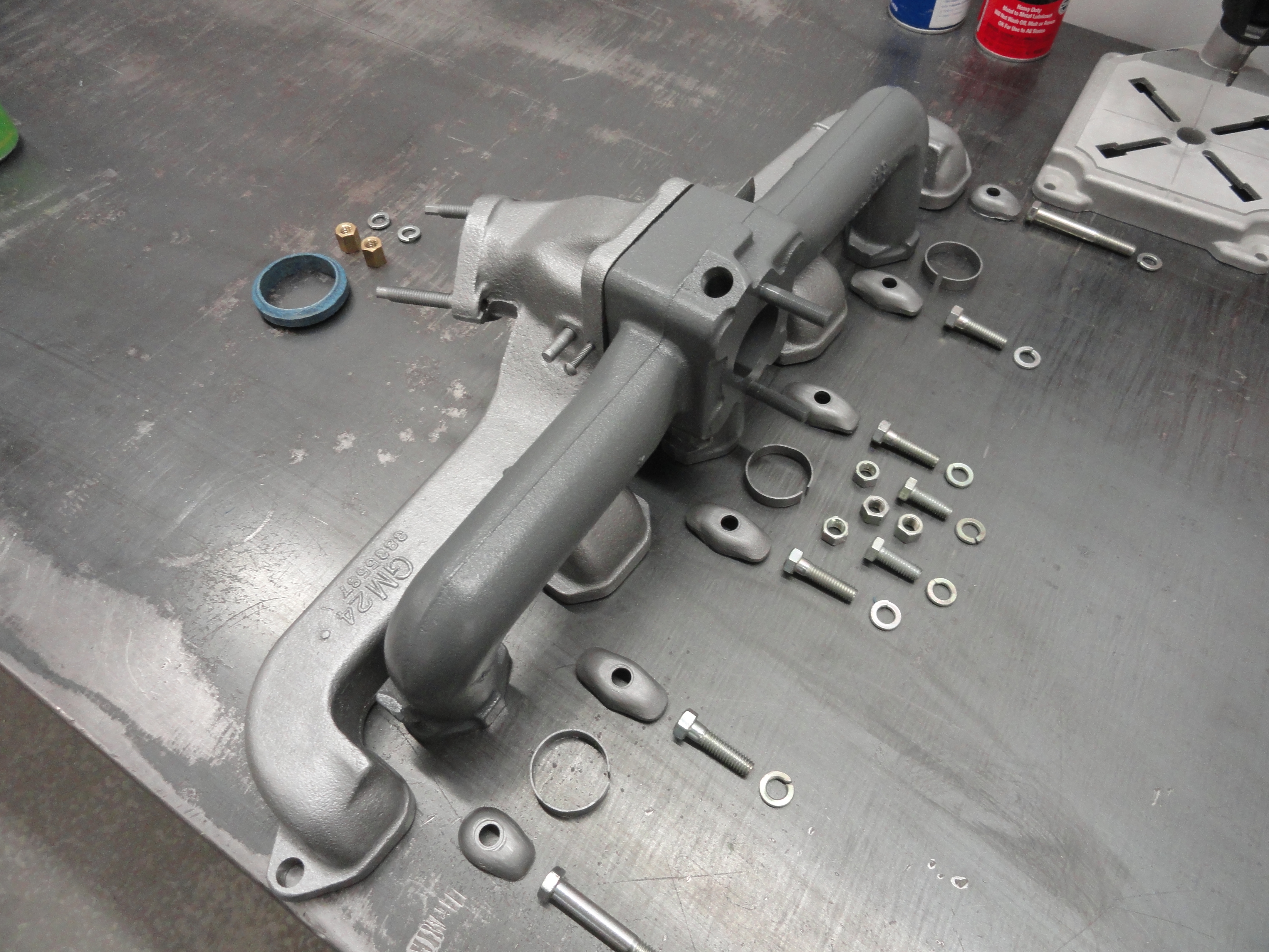
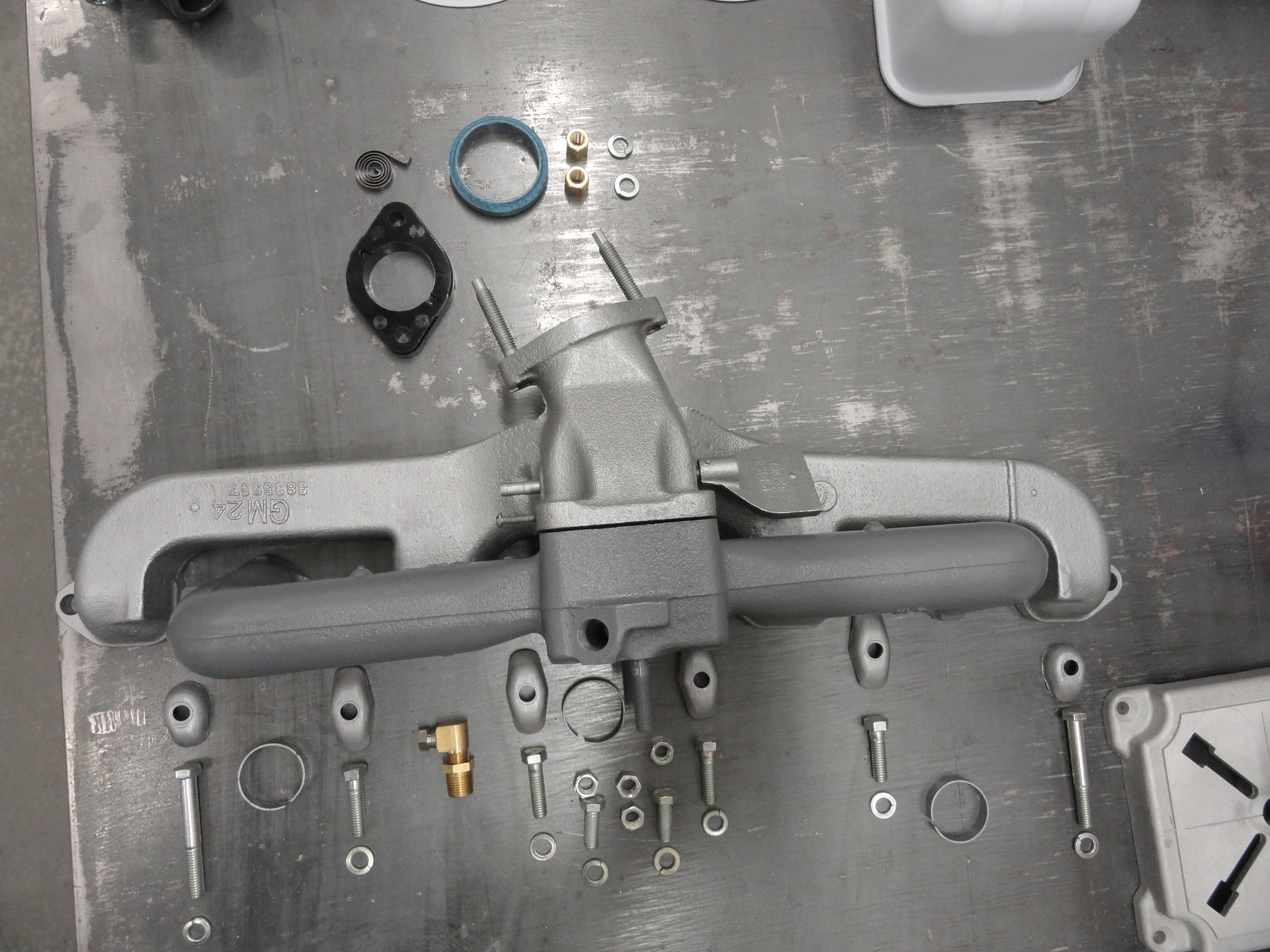
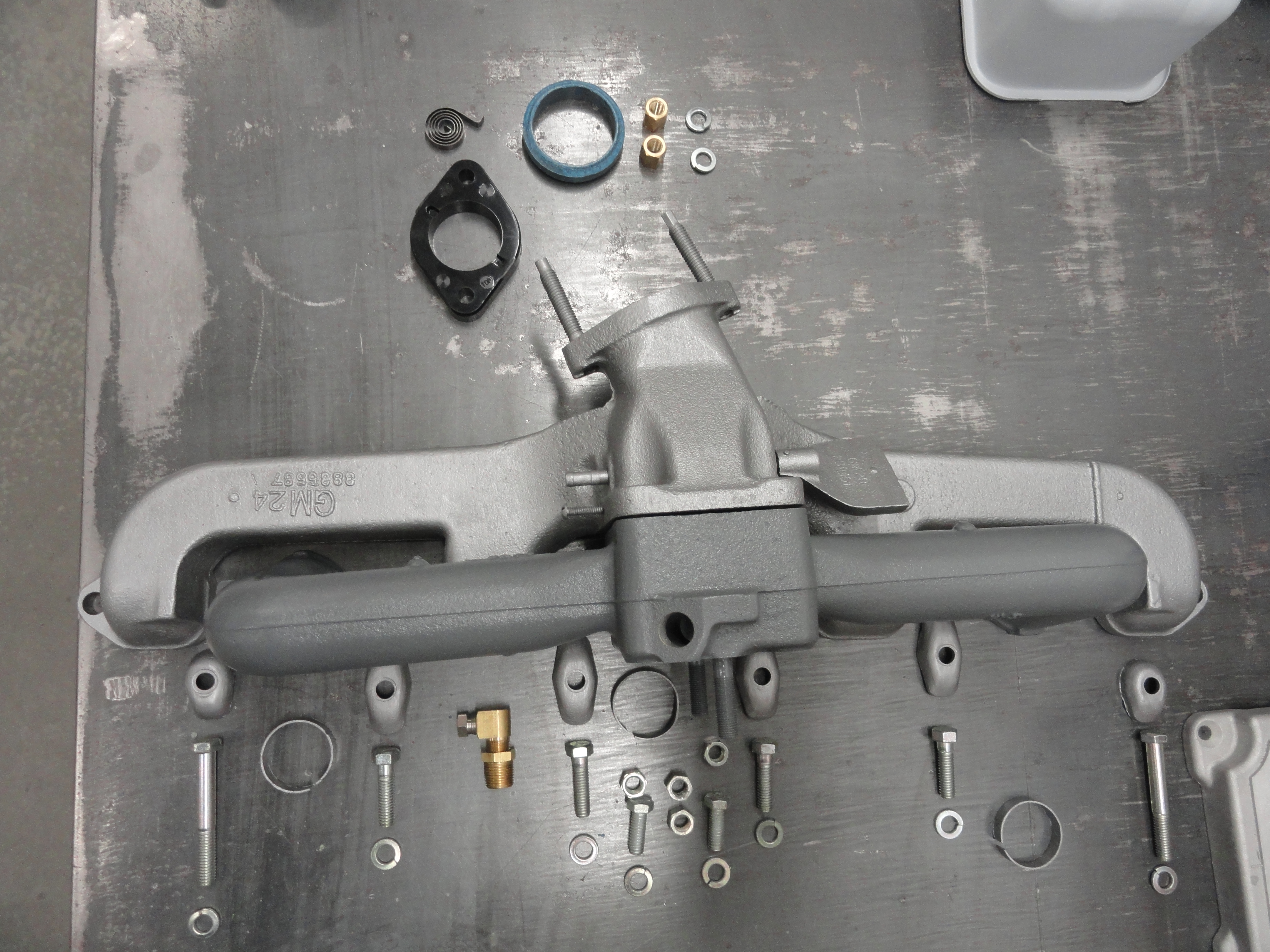
First off, these exhaust manifolds are starting to show their age. I see many cracked ones that are not usable. Some of this is because when some people pull the engine, they put the chain around the exhaust manifold. Please do not do this! The walls of the manifold get thinner and thinner and we are at a point now where they are getting harder to find. Then, if you have one with no cracks, does the butterfly valve rotate freely? In a lot of cases, no. Then there is a stud that the Exhaust Manifold Heat Spring connects to. It's broke off or rusted almost to non-existence on many of them. What about the exhaust pipe studs? If they are not perfect, you will want to replace them. There is no way to state "They are hard to get out" and exaggerate! Once you have all of this addressed, let's hope we don't have a warped manifold and it bolts nicely to the Intake and the Engine.
I have one that we can start with. It doesn't have visible cracks. The heat spring stud is broken off and the exhaust pipe studs need to be replaced. The butterfly is frozen solid. Let's see if we can save it. This takes lots of patience and prep work. Anytime you run across a vintage part, have the PB Blaster handy. They should make a hip holster for this stuff because in this business, it's what you draw when you draw! In the case of this engine, the Exhaust manifold was cracked and had to be replaced. Not just a little crack. but almost completely broken in two near the center of it. I found a replacement and it had a completely stuck butterfly valve, the stud that keeps the spring tensioned was broken off, and one of the two studs that hold the exhaust pipe on was broken. These are things you expect on this vintage vehicles. I drilled out the spring stud, tapped and replaced it with a long screw. The head of the screw will keep the spring from slipping off.
I then used PB Blaster over a few days to attempt to loosen the butterfly valve. Although very tight to begin with, in the end I got it going again with a few taps of the hammer and more gentle prodding. The exhaust pipe stud was not coming out and I didn't want to break the ear off and end up with another junk manifold. If you know how to drill and tap into metal, you can just grind off the stud smooth with the surface, then with a center punch, punch in the center (that's the hard part) and making sure you are in the center, drill starting with a 1/8" bit them move to 5/16" which is the correct size for the 3/8"-16 tap. This isn't easy to get right, but there wasn't much choice. Heat didn't do the job and of course I tried double nutting and just stripped what was left out. Once you get the hang of the drill/tap procedure it's really nice to have new studs on this fresh engine. Once all the threads have been chased and cleaned it's time for paint. I use a 2000 degree manifold paint. The color states Stainless Steel. I got it from one of our vendors sold as a correct color for a stock 47-55 engine which is what we are going for. The Intake Manifold is Engine color which is Medium Gray. Once painted and ready for installation, gather up all the necessary bolts, nuts, washers, and fittings and that subsystem is complete.
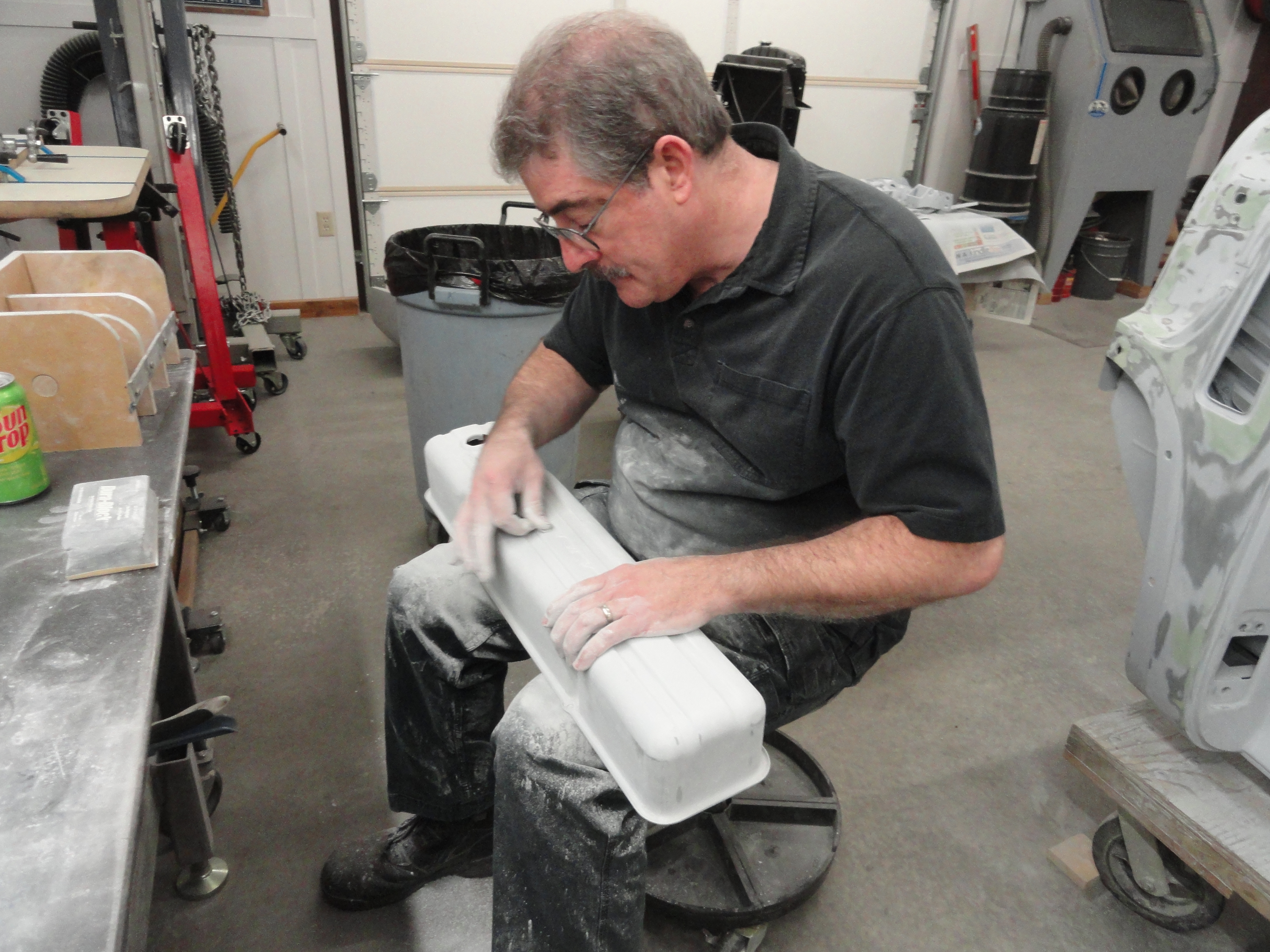
The following parts will need to be prepped and repainted:

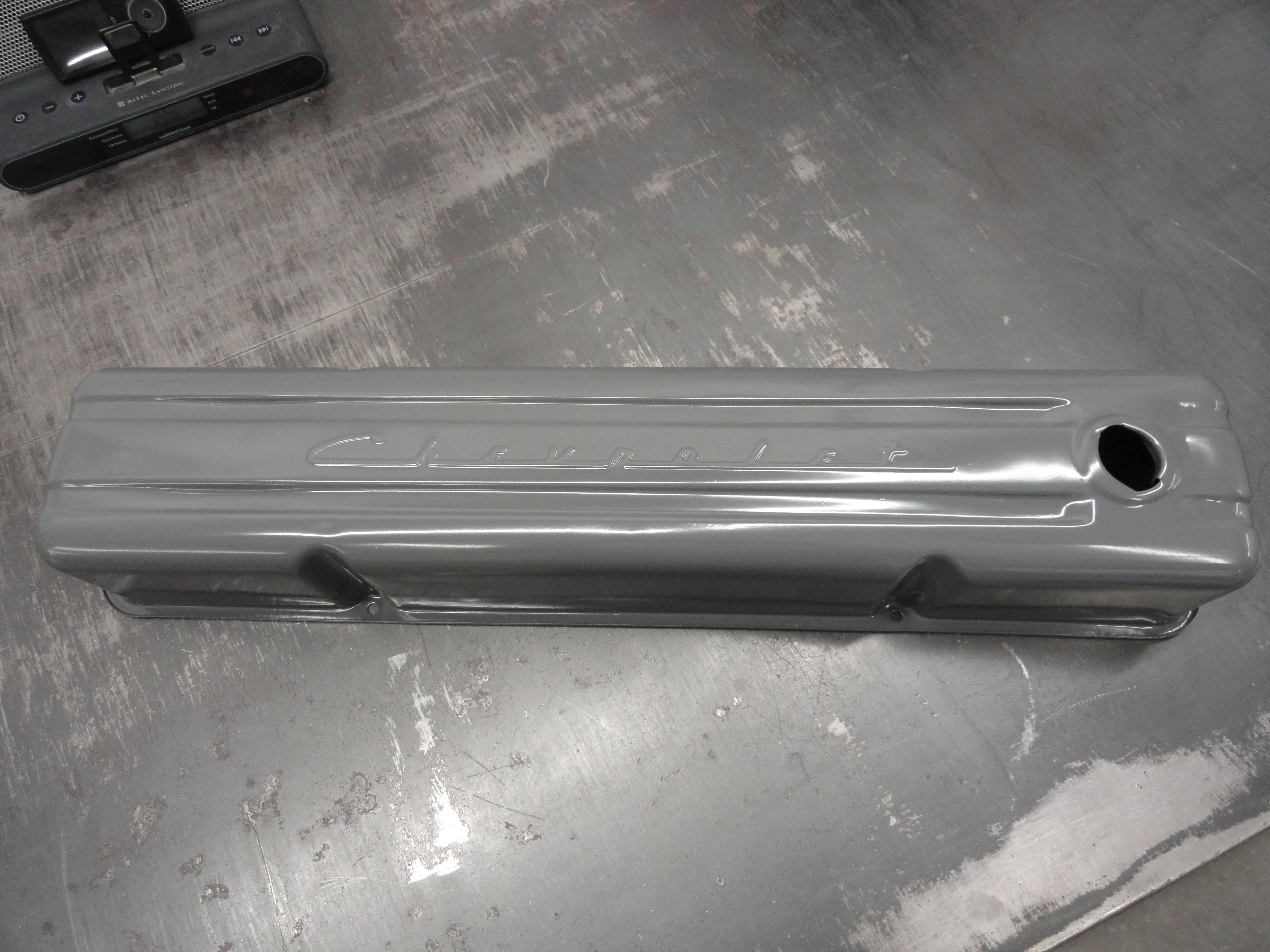
To accomplish this I didn't just go out and get a case of spray cans, although it is worth looking into because today's spray paints are of much higher durability than in the past. First everything is sandblasted, then 400 grit sandpaper taken to all the parts. I can see the imperfections that way. Imperfections are hammered out, damage holes and rust-through are welded shut, each part carefully attended to. Then, PPG DX330 Metal Prep is thoroughly applied and since I use paper towels, I like to use clean compressed air to remove any fibers or residue. I then proceed to apply PPG's DPLF Epoxy Primer on all of the surfaces that will not be coming in contact with circulating engine oil. This product is rated up to 500 degrees, just like the engine paint we will use. This will be a very durable finish. In the case of the Valve Cover and Air Cleaner, I went the extra mile of adding Urethane High Build Primer (PPG K36) and sanded with 400 grit paper prior to the paint step. I then applied 500 degree Engine Paint in Medium Gray. This is to replicate the look of a Chevy 6 cylinder Truck engine for the years 1947-1955. Everything but the Cooling Fan, Air Cleaner and Oil Dipstick handle which I like to use 500 degree gloss black. (looks great with the stainless steel dipstick tube). Taking a little time to add value to the engine by making it look like it is going into a treasured vehicle is the least we can do for this venerable engine.

The flywheel then gets a bit of special attention. The BB is shined up really good using a Dremel then the flywheel is marked for clarifying the timing positions. This makes life so much easier when static timing the engine. The way this is done is outlined HERE. But since it is pertinent to this rebuild, I will go into detail here as well. Most truck owners do not realize there are two different flywheels that are possible on your 1954-1962 235/261 engine. This matters a great deal and you should be aware of which one you have.
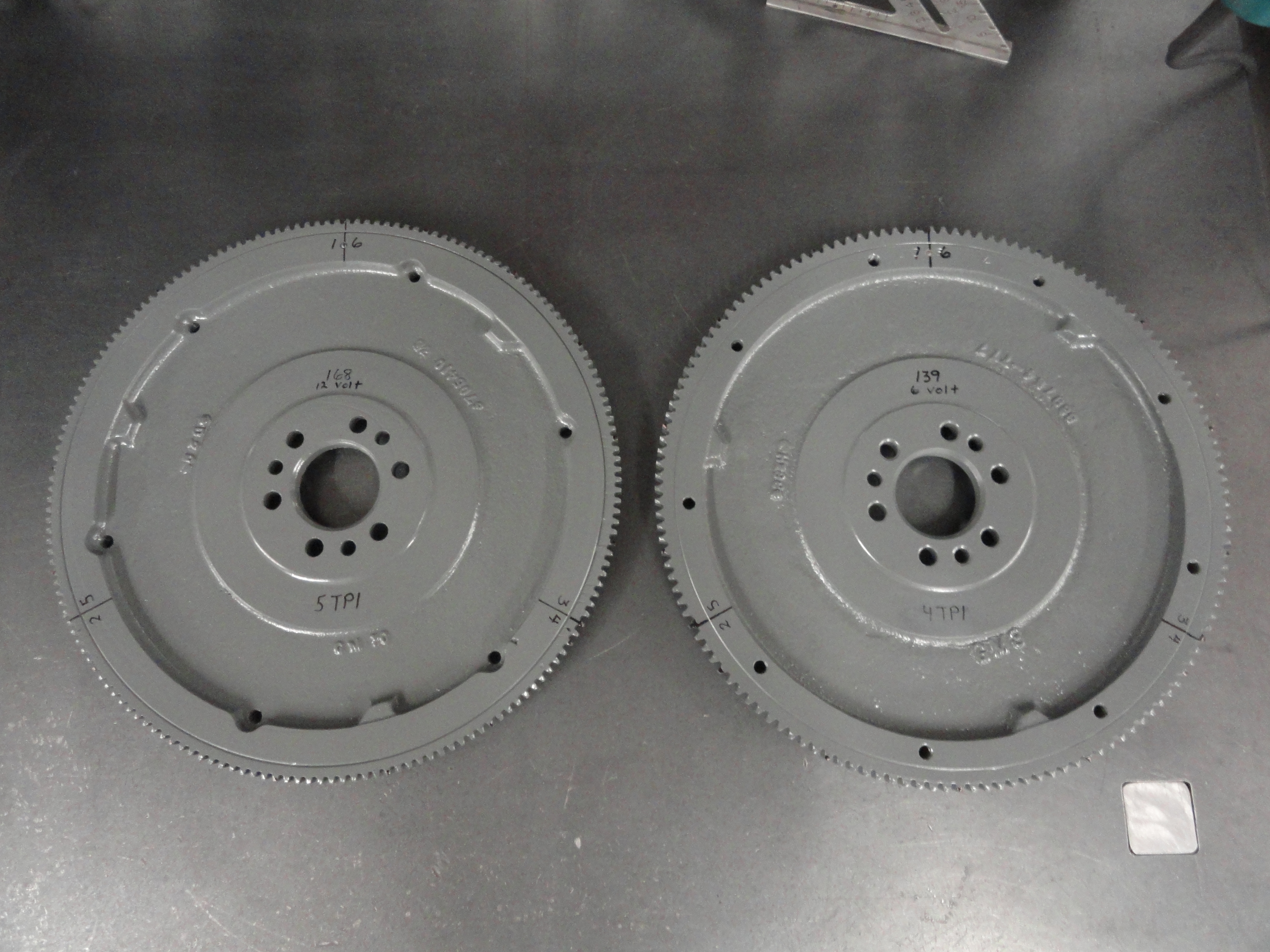
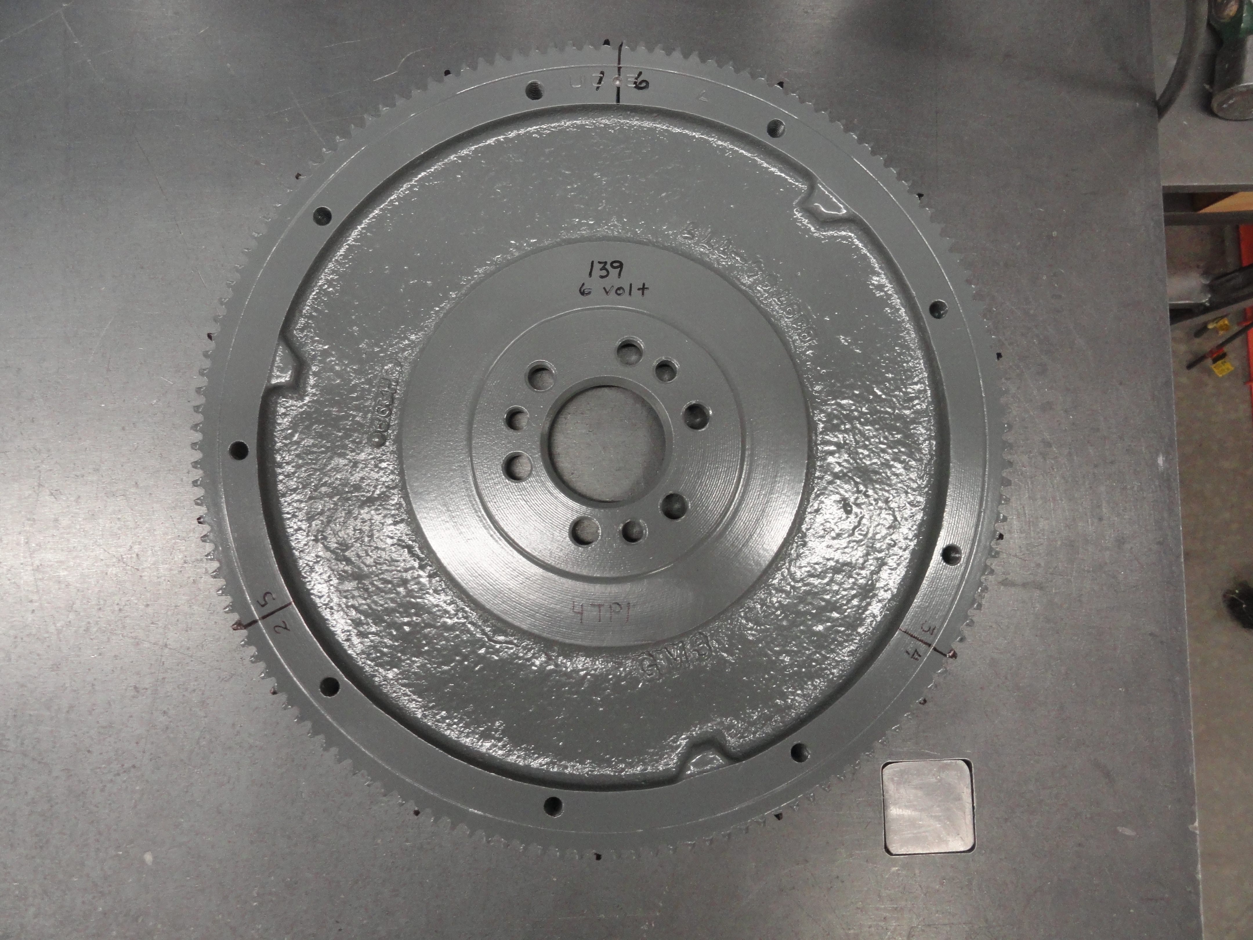
Since the 1942-1953 216 engines have flywheels that are totally compatible with the newer 235, many folks opted to go with the flywheel off of their old 216. The reason why has to do with the trucks system voltage and the Starter. The old flywheels have a 139 tooth ring gear and all Starters until 1955 were 6 volt. They also have a 6 volt starter drive gear that only engages in a 139 tooth (4 teeth per inch) ring gear. This does not mean that if you have a 12 volt system, you for sure have one or the other flywheel. That is because the 6 volt starter works just fine in a 12 volt application. The reverse is not true.
This is because the 12 volt Starter has a starter drive gear that is only compatible with the 168 tooth (5 teeth per inch) ring gear of the newer style 235/261
engine. To make things more confusing, you can get the foot controlled starter in either 6 or 12 volts. Someday, you will need to purchase a new Starter for
your truck. It would be nice to know which one you need. So while it's out of the truck for this project, shine up the BB so it can be seen through the
Bell Housings Timing hole, then mark your flywheel according to the following.
If you have a 139 Tooth Ring Gear on your Flywheel:
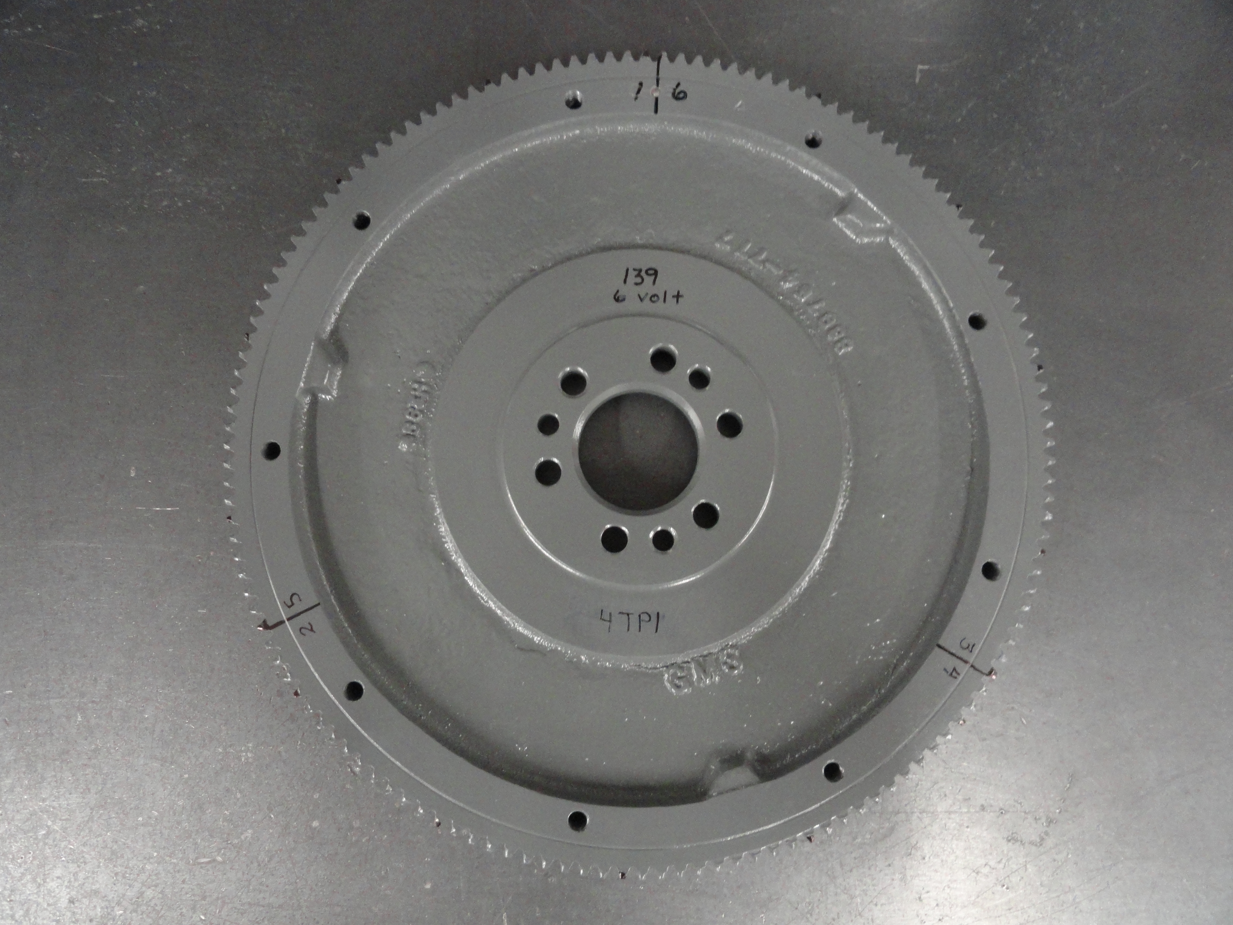
Now you will have a much easier time with static timing and valve adjustments because you will know for certain which set of cylinders are at the top of their travel. If you have a 168 tooth ring gear on your flywheel, Substitute the number 56 wherever you see a 46 above.
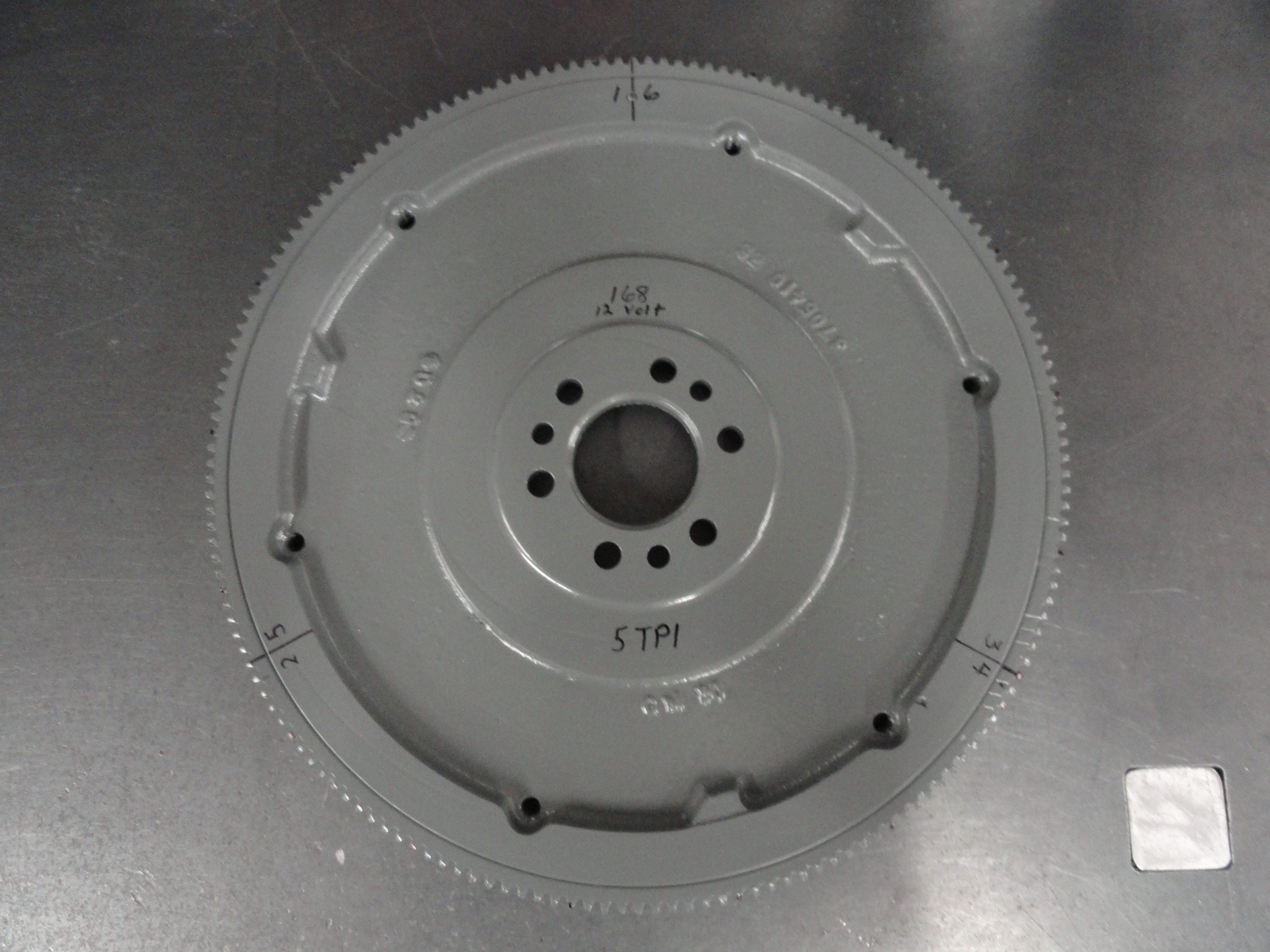
It is also a good time to look over the teeth to make sure the starter will engage properly. If you see excessive wear, it may be a good time to remove your ring gear and turn it over, or purchase a new one. Ring gears are pressed on and can be heated with a torch then they almost fall off by themselves, or with a brass hammer or brass punch, slowly work your way around being very delicate so as not to warp or damage the ring gear. To re-install it, you will need to put the ring gear in the oven at 400 degrees until its thoroughly hot, then very quickly put it back on before it cools. Ring Gears are not indexed in any way, so not to worry about how it's placed.
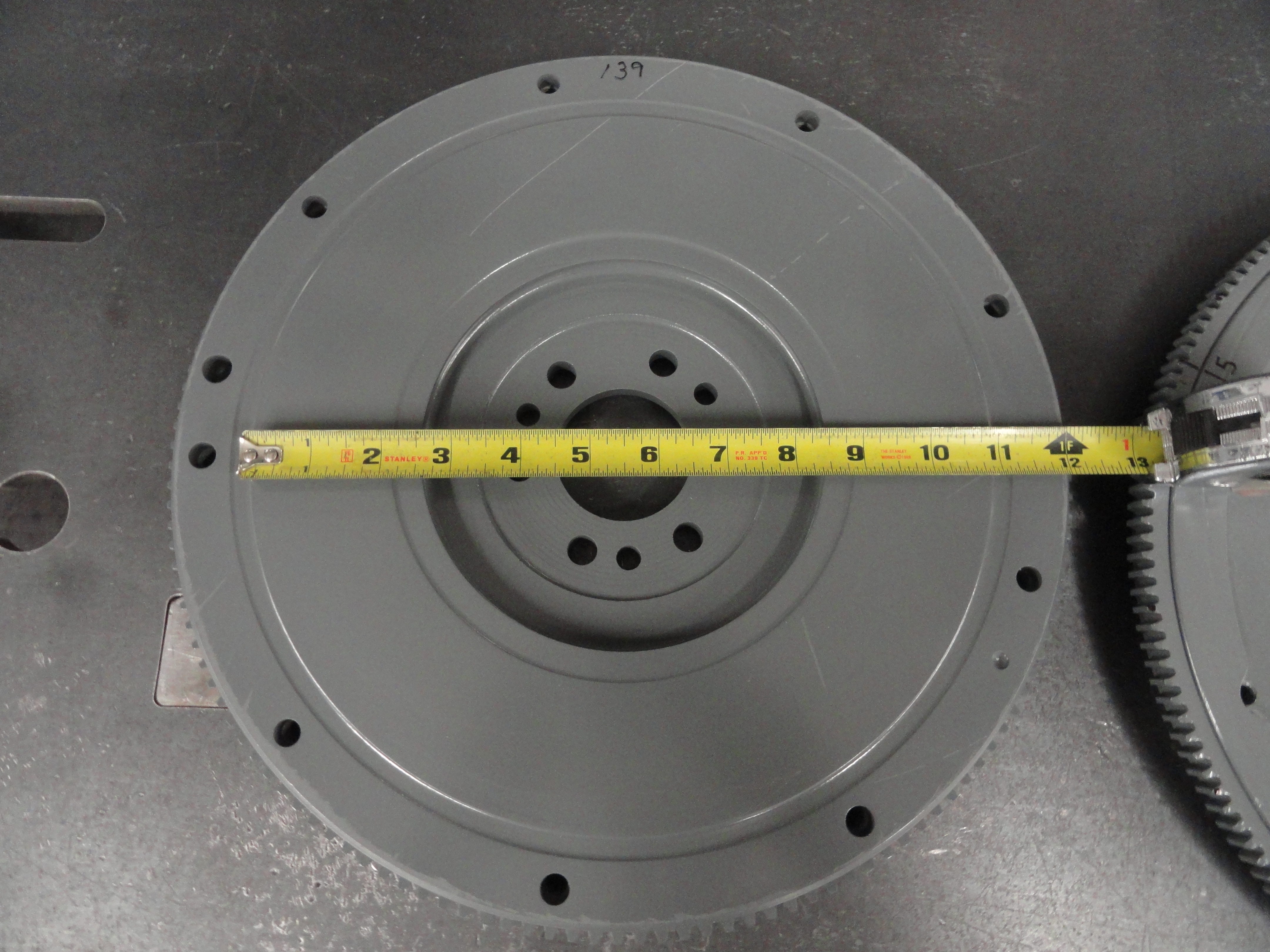
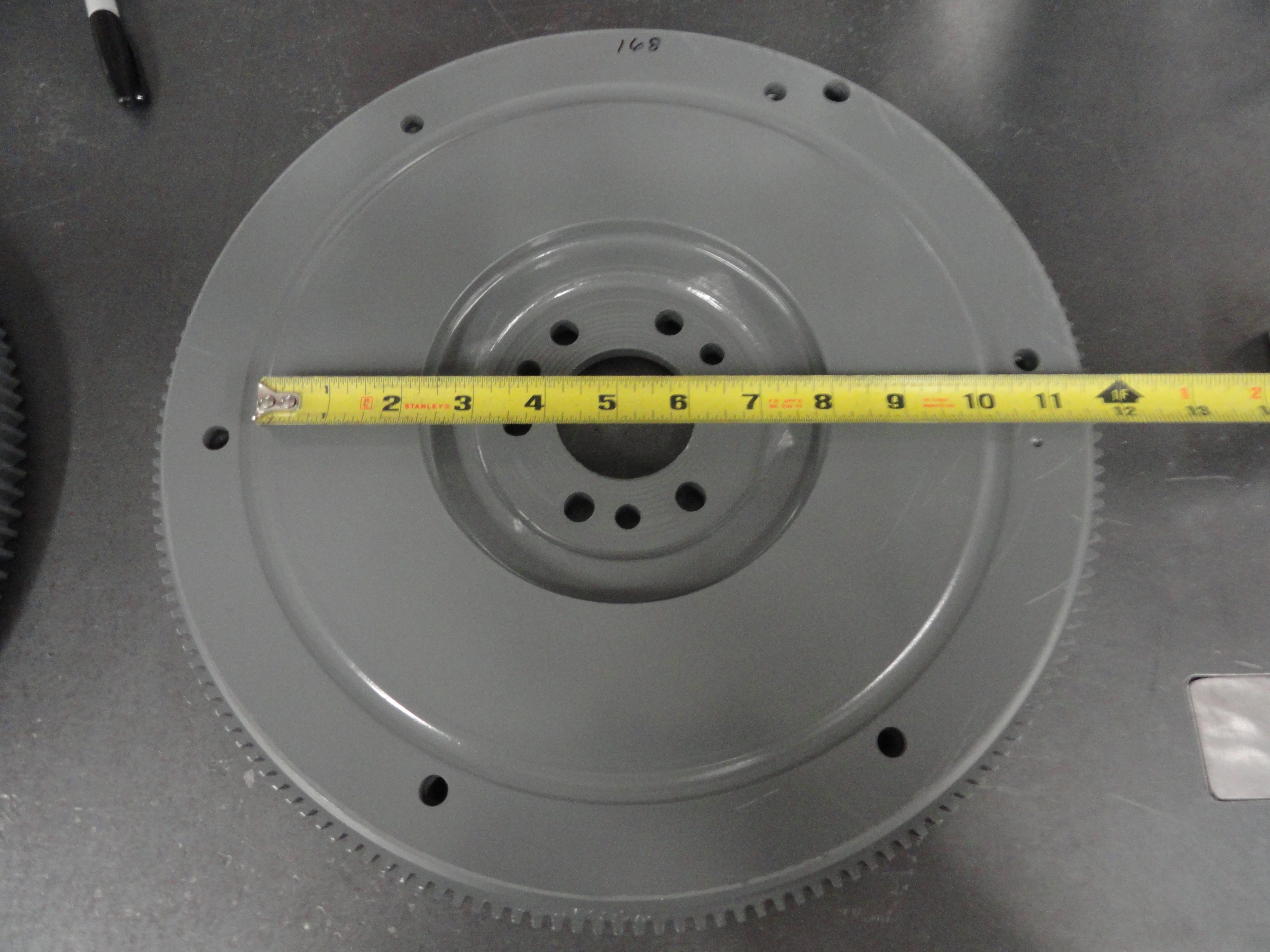
In addition to the considerations above, it's also a good idea to know what clutch size is correct for your flywheel. On the back of the flywheel is the clutch
plate mating surface. If the surface of your flywheel has a mating surface of 9.5 inches, you can only install the 9 inch clutch. If your flywheel has a mating
surface of 10.5 inches, you can install a 9 or 10 inch clutch. 11 inches for an eleven inch clutch. Clutch discs commensurately come in 9", 10", 10-1/2", and
10-3/4" diameter sizes. Pressure Plates came in 9-1/2", 10", 10-1/2" and 11" inch diameters. When purchasing your new clutch parts, be sure to get the proper
throwout bearing for your clutch assembly. The point being, tell your parts man the size of your flywheel mating surface to get the proper parts. Don't assume
the correct parts were already in there. The previous owner could have installed whatever parts were available without knowing that most of these parts are
interchangeable even if it's not a good idea.
Taking the time to do these things will give you more information about your truck and take a lot of the guesswork out of it.
There are small things for this particular build that may or may not pertain to your rebuild project. Worth mentioning are things like the differences in water pump installations. For our rebuild, we want this engine to fit into a 1947-1955 AD Chevy 1/2 Ton. To appreciate the problem, if you were to look at a 216 engine installed in this era truck, you will notice the fan blade is EXACTLY in the center of the radiator. But, if you installed a newer style 235/261 you notice the fan is substantially lower and the difference is enough that one could argue the cooling system is not as efficient. To fix this problem, our good friend Dave Folsom has created an adapter plate that allows the water pump to be installed higher, and in the exact center of the radiator. This is a $50 plate, but the water pump used has to be short and of the proper V-Belt width. So, the perfect water pump for this upgrade is the 1953/54 pump listed in the Parts List. Turns out the formed radiator hoses will work just fine anyway. Another issue that isn't mentioned often is you have to install a 216 cooling fan on that water pump since the newer style 235/261 fan is not compatible. I already had one, but if you need one, Jim Carter sells a stock 216 fan. They are slightly smaller but they cool really well. I used this exact setup on my 261 and am very happy with it.
In addition to the water pump change, we also want the PCV system to increase engine longevity. With a filtered breather style Oil Filler Cap, we can remove the old Road Tube... you know, the one thats leaking drip...drip...drip all over your precious concrete and replace it with a more modern and much more efficient PCV System. This consists of a few fittings, a grommet and tubing from the road tube to the intake manifold. This entire system is described HERE. The part numbers are in the Parts List. All there really is to it, is to get a 1-1/4" cup style freeze plug, drill a 3/4" hole in the center, install the freeze plug with the cup facing up down 1/32" from flush with the engine block, then use gasket sealer to glue the grommet into the cup. Place the PCV valve in, plumb it to your intake manifold with 3/8" hose and you are all set. Just be sure to use a filtered breather style oil filler cap.
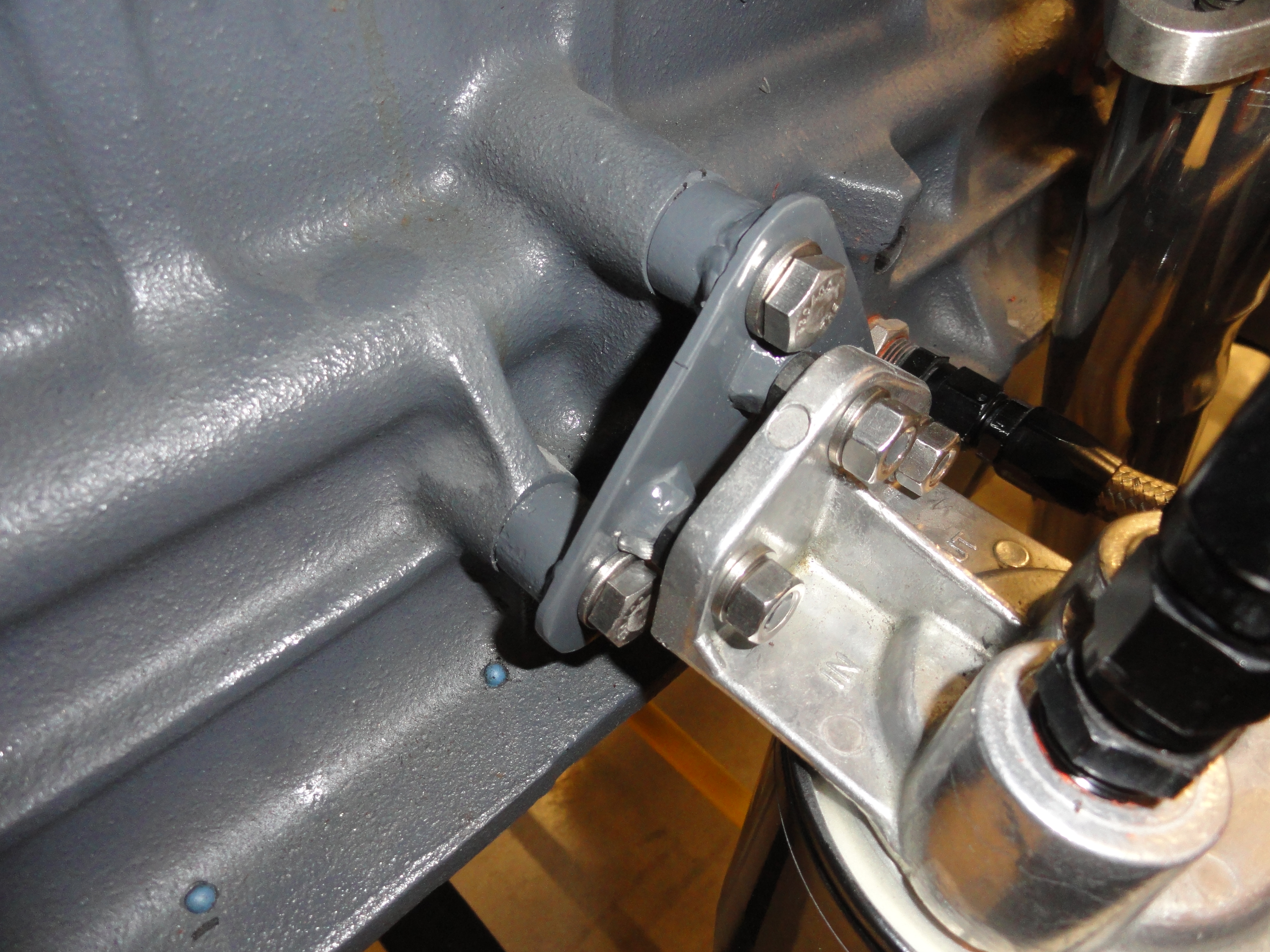
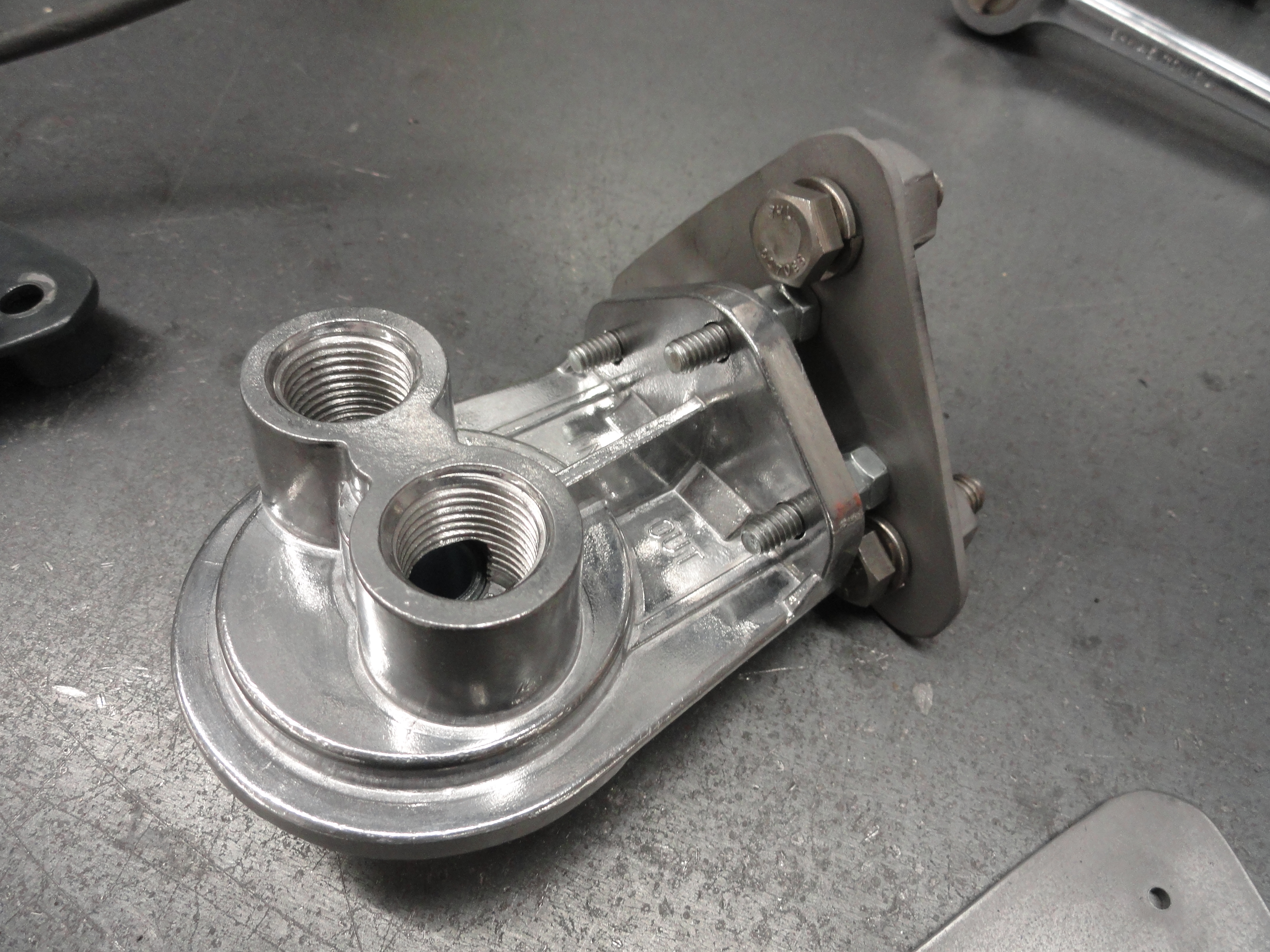
Another modification I opted for was a Spin-On Oil Filter Adapter to go with the Machine Shop modifying the engine block for full flow oil filtration. I found a really cool place to put the adapter. The newer 235 engines have a triangular side engine mounting boss. Three 3/8" bolts are used to hold the engine in place on a newer style truck. Since we are setting this engine up for 1947-1955, the engine will be mounted at the front on the timing plate. This leaves those three holes for us to mount our Spin-On adapter direct to the engine. This is the best way because any torquing or engine movement will not cause stress on the adapter or hoses. It would be nice if they made a Spin-On Oil Filter Adapter that just had that bolt pattern, but no, we have to make an adapter for the adapter! Not really much problem if you have rudimentary metal working tools. If you don't, you can always check out the Farm-It-Out section at devestechnet.com. Meanwhile, to make this thing, we need some 1/8" plate, some cardboard, some hardware and some patience. Start by placing a piece of cardboard up against these triangular bosses and hold it very firmly, take a hammer and just tap around the cardboard to get the pattern. Use a ball peen hammer to tap inside the holes so that they also show really well. Once you have the outside pattern as well as the hole pattern, cut it out with scissors and place it over your 1/8" plate.

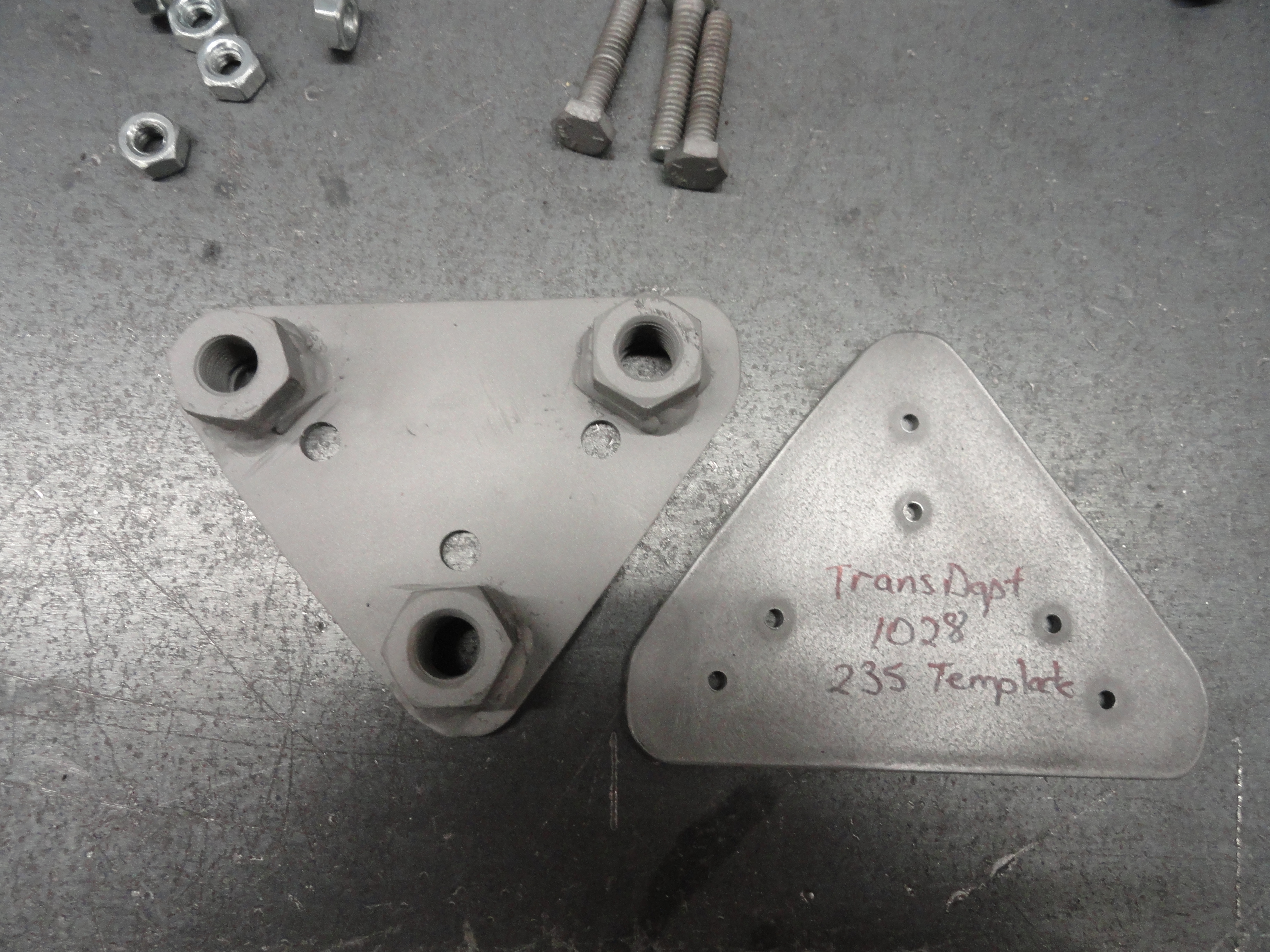
With a band saw or whatever you use to cut the metal, cut your triangle out, then position your center punch in the center of your hole pattern (I just place the cardboard over the metal and center punch both), and drill your 3 engine mounting holes to 13/32". This is two fractional sizes larger and should forgive very slight mis-measurement. Once those holes are drilled, it's time to mark the plate for the 3 triangular adapter hole pattern. This is a little tricky, but lay it out as shown and just stay away from the larger holes as much as possible. There IS room for the heads of both patterns to NOT interfere with each other. Drill these holes out to 9/32" which is two up from 1/4". Test to make sure they line up perfectly with the adapter. I found that 3 of 7/16" lug nuts work best for the standoffs. They work perfect because of the bevel. Perfect for welding the bead around them to secure to the plate. Once you have tested your holes on the engine block and everything is right, weld the lug nuts on the plate, then test it on the engine block again. Use 3 of 3/8 x 1-1/4" Bolts for the engine block part.

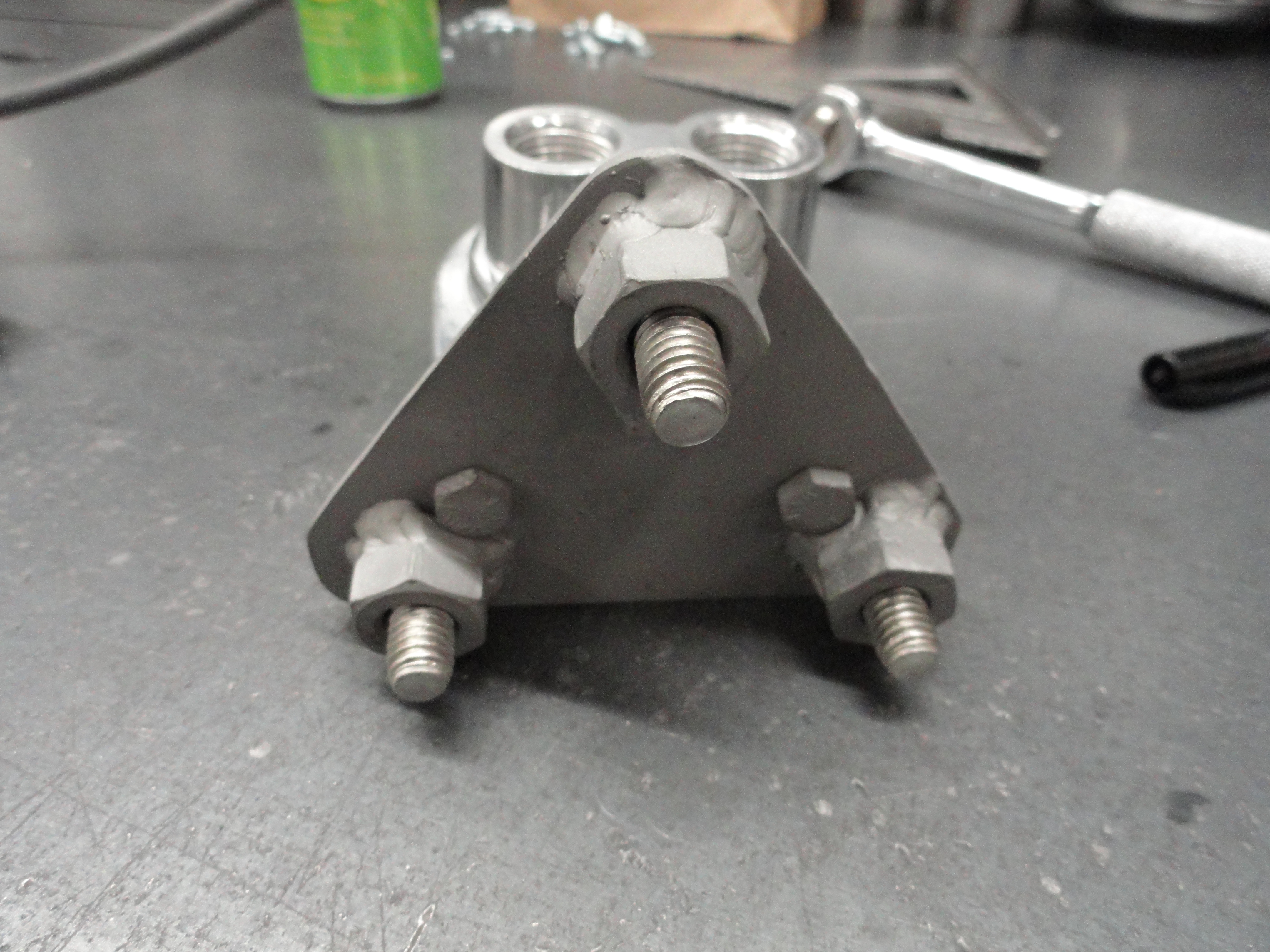
Next get three 1/4" x 1-1/4" grade 5 bolts. The problem with these bolts is they are usually not threaded all the way up, and we need them to be. So, if you can't find any bolts that thread all the way, get out your 1/4" x 20 tap and finish the job. If you use oil and take your time, the nuts will turn easily all the way down. Install these bolts in so they stick out opposite the lug nuts as shown. Run one nut all the way down and tighten the bolt to the plate. Run a second nut down on to the first nut securely. This is used for the proper standoff so the engine bolt head has room. Paint the piece to keep it from rusting. This is the perfect location for the adapter and doesn't interfere with anything when it's mounted. The last thing you will need to do is figure out the fittings you need to install the hoses. I am using 1/2" NPT (the inlet/outlet holes in the adapter) to -6AN adapters so that I can hook up 3/8" stainless braided hose. I will wait to get excited about doing that until after the engine gets back from the shop.
Prepare for the engine to arrive by making sure you have all of your hardware, fittings, sheetmetal work, everything completed so that you have as few surprises as possible. Read the shop manual for your engine to make sure you have all of the tools, and confidence you need to complete the task. Ask lots of questions and do your research. It will make this rebuild so much more fun. Other things that could be done is purchasing new fuel, vac advance, PCV lines, accelerator linkages, springs, etc. Also, gasket sealer, engine assembly grease and lube, break-in oil, etc. Since we are getting our gasket set from the Machine Shop, there isn't much left to do other than wait!
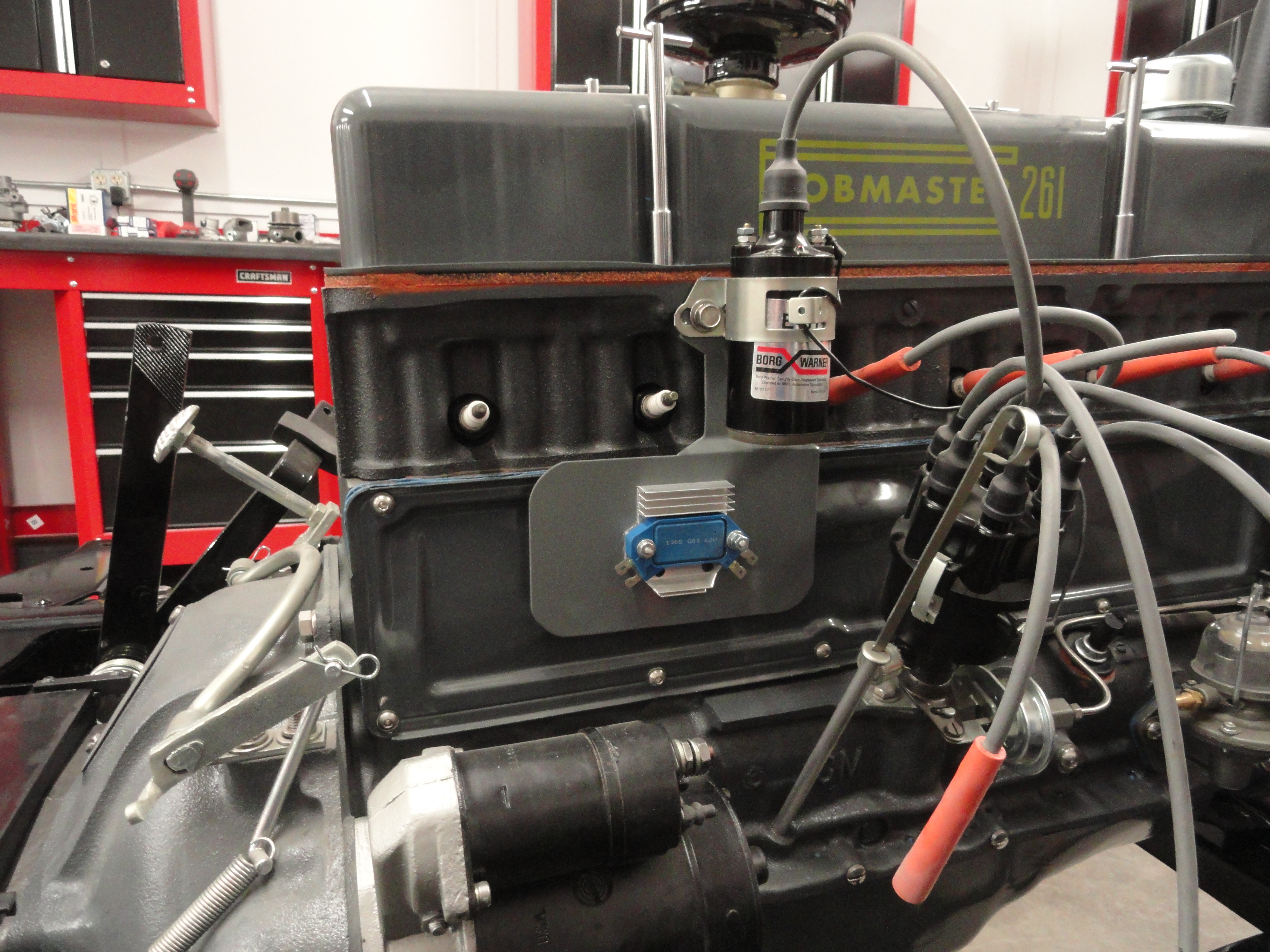
During initial engine rebuilding, we will use a Points Distributor for the initial run-up, then once everything is tweaked to perfection, change over to a new HEI System that was initially devised for this vintage engine by Jim Linder of Bubba's Hotrod Shop. The system uses your stock distributor and without modifying any of the vintage distributors internal parts. You can read all about it HERE. The problem comes in that for a stock enthusiast you don't want a visible nasty looking HEI Module showing anywhere. Well, I can't help you there, but I feel I came up with about the best solution considering. I wanted the Module very close to the Distributor and Coil, so I made this plate that bolts on to the coil bracket, allows air to flow across as well as behind it for better cooling, and if I decide I just can't stand the look, I will use an old Delco-Remy Regulator Box, gut it and place it over the top of the module on this plate giving it more of a retro look. You can read much more about this adapter plate and the entire system at that link above. This is the entire reason for me needing a test engine, so I am very excited about it.
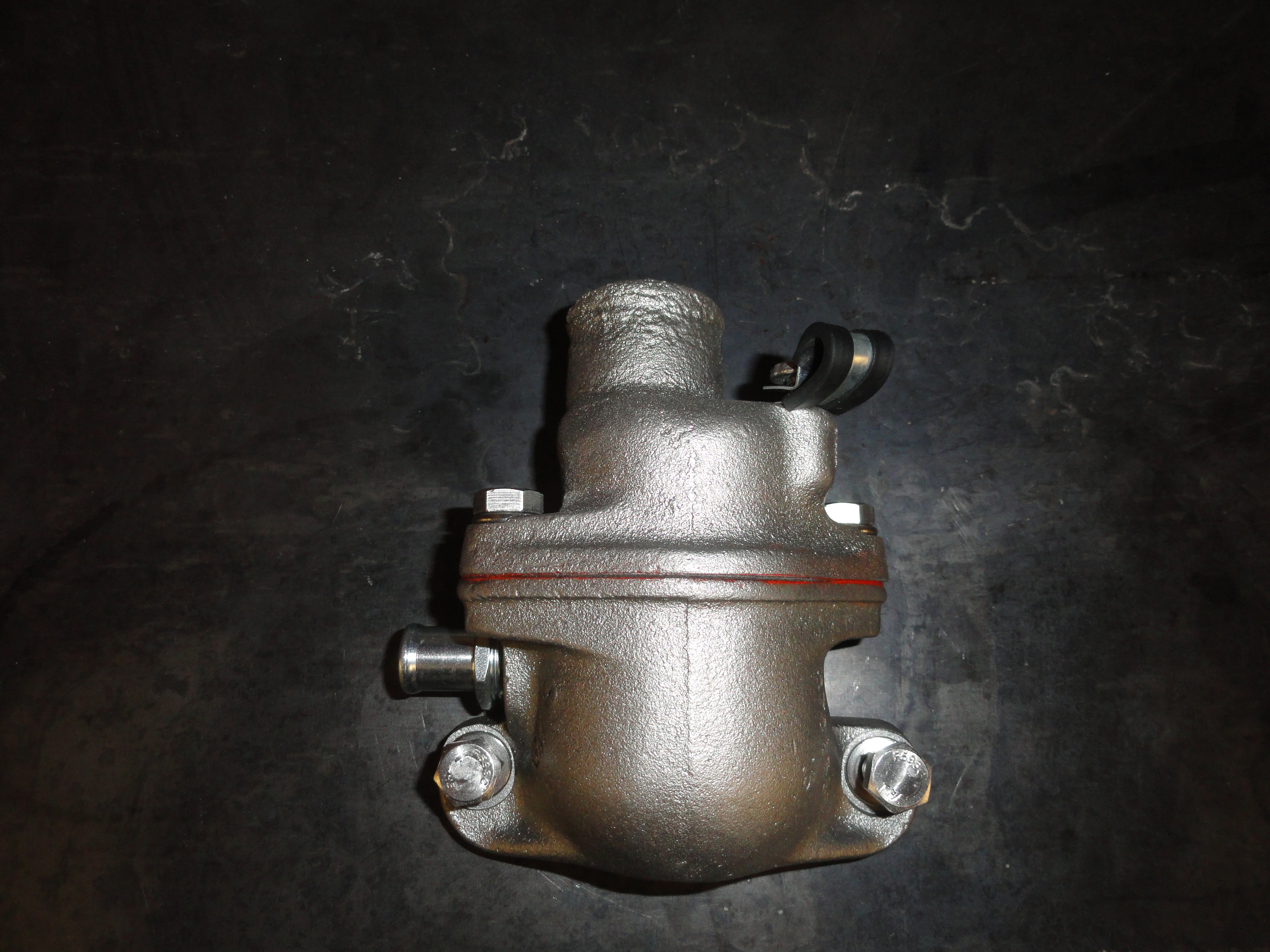
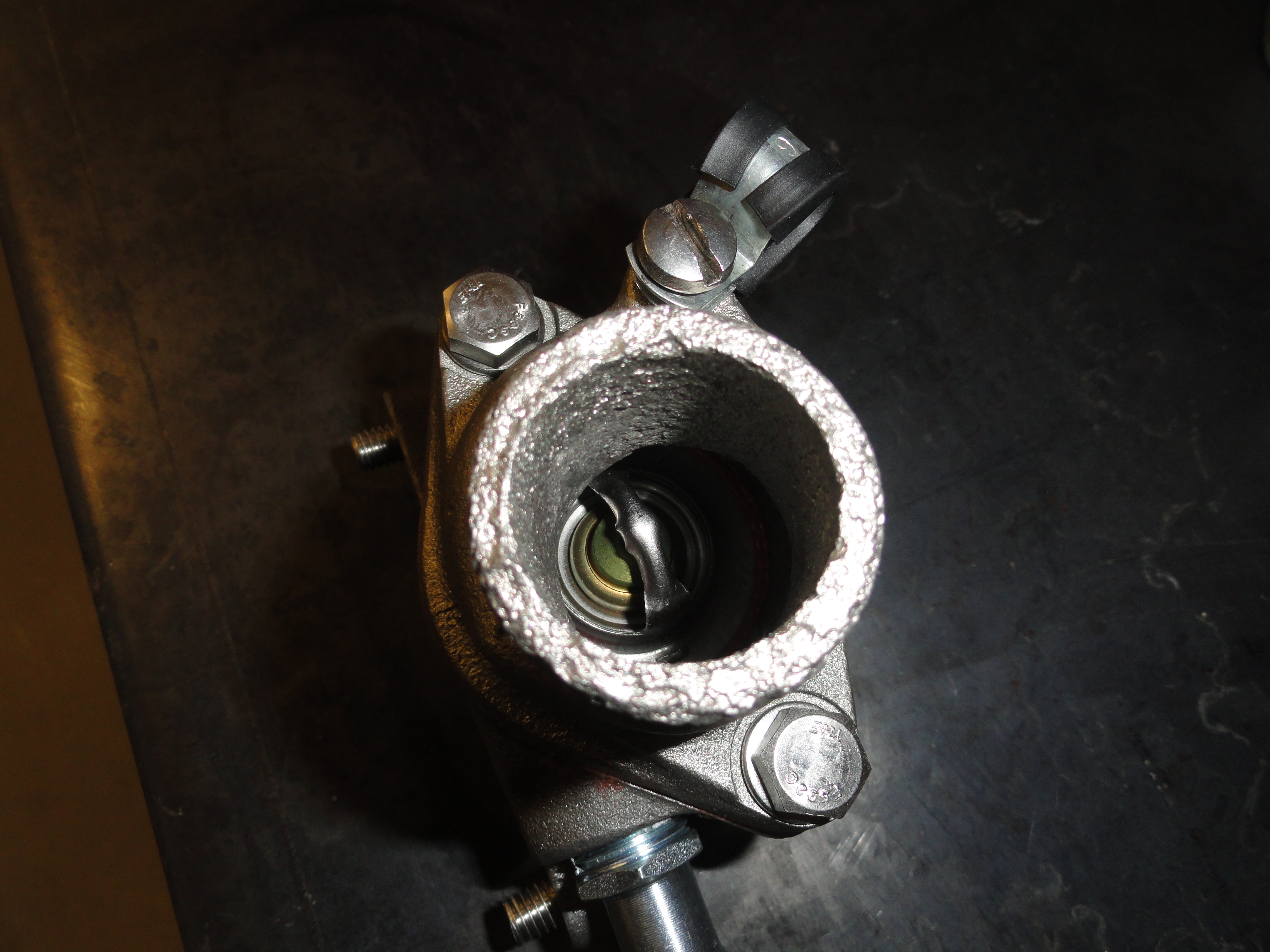
I want to be sure to cover the small things too, so let's put the thermostat housing together. I like to use high temperature gasket sealer on almost everything. Seems added insurance. A gasket comes with the rebuild kit. I happened to have an extra left over from another project. The important thing here is to get the thermostat in the right direction. The spring is DOWN when installed on the engine. I took a few pictures of this assembly so you can see which is the proper way. I also use plumbers teflon wrap around the heater hose barb. I got a StoreHouse with those rubberized clamps for the fuel line, and found all the proper bolts for installation. When the engine gets back, we will be ready. The pitting around where the hose connects is unavoidable I'm afraid. I haven't seen better ones in a long time. If you have the fitted upper radiator hose, you can install that to the top of the housing now too. This is a chore! The hose diameter is too tight so it takes some real work to get it on. Use grease to make it easier.

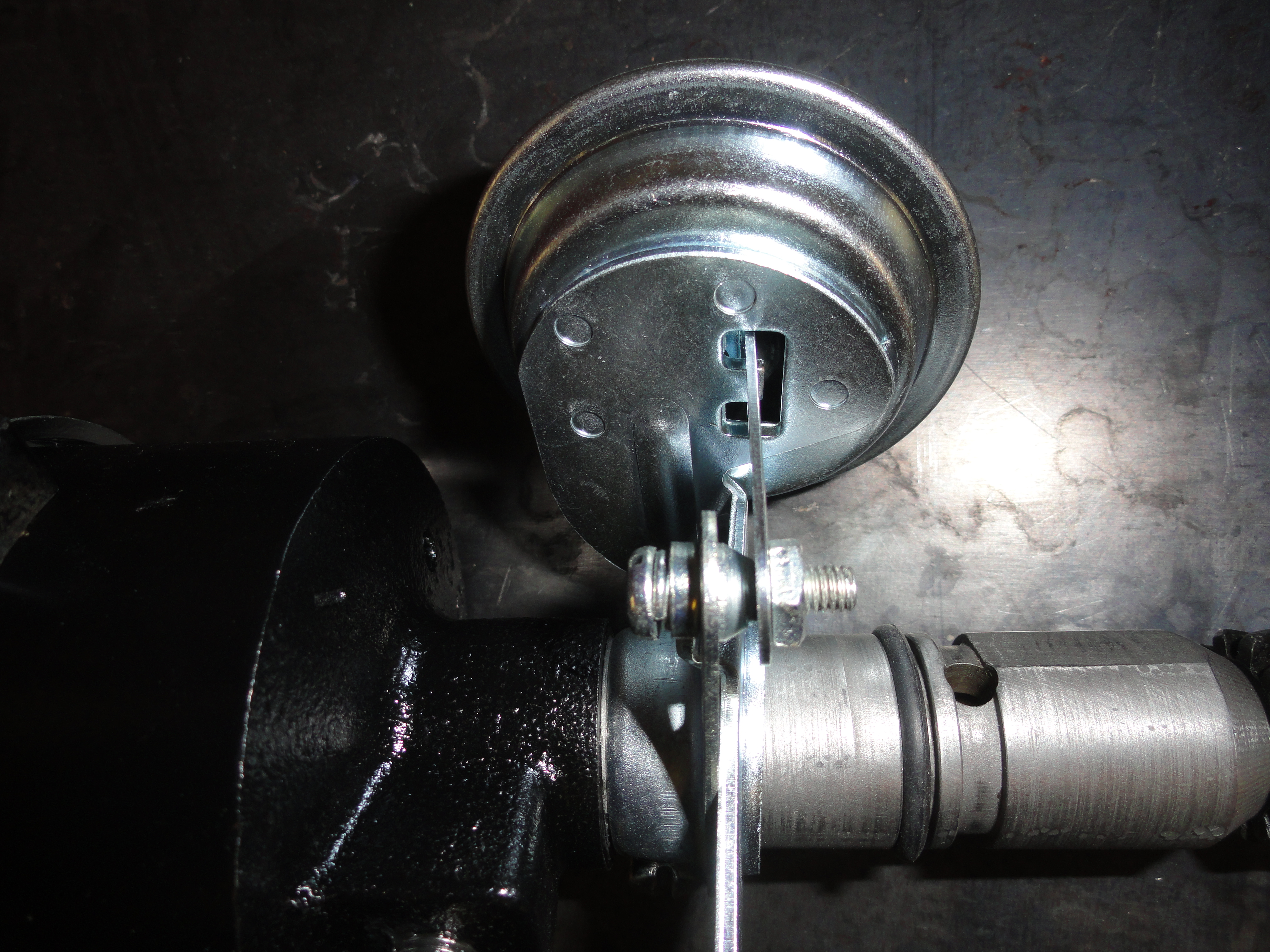
The Distributors Vacuum Advance is a very important part of the timing system and must be in good working order. I find it best to just order new ones because it is
impossible to tell how long the used ones will work. They do not come with everything you need! The part that tightens down to the Distributor shaft is something
you need to keep from your old one. I didn't have the right one, but I made do with a different connection at the diaphragm arm. You want your vac unit to be
pointing forward to be correct. If you are using the Car version of this vac advance and already have the tubing to the carburetor, that will work too. You just
want to be sure your bracket is compatible with the new unit.
The first installment is Jim working on drilling the crankshaft for that 7/16"-20 hole I wanted to bolt the Harmonic Balancer in place. This is a popular thing to do to these old engines because the Harmonic Balancer is just pressed on and has been known to fall off causing severe damage. Since there isn't alot of commentary needed from me, I will format this section a little differently so the pictures will all be together.
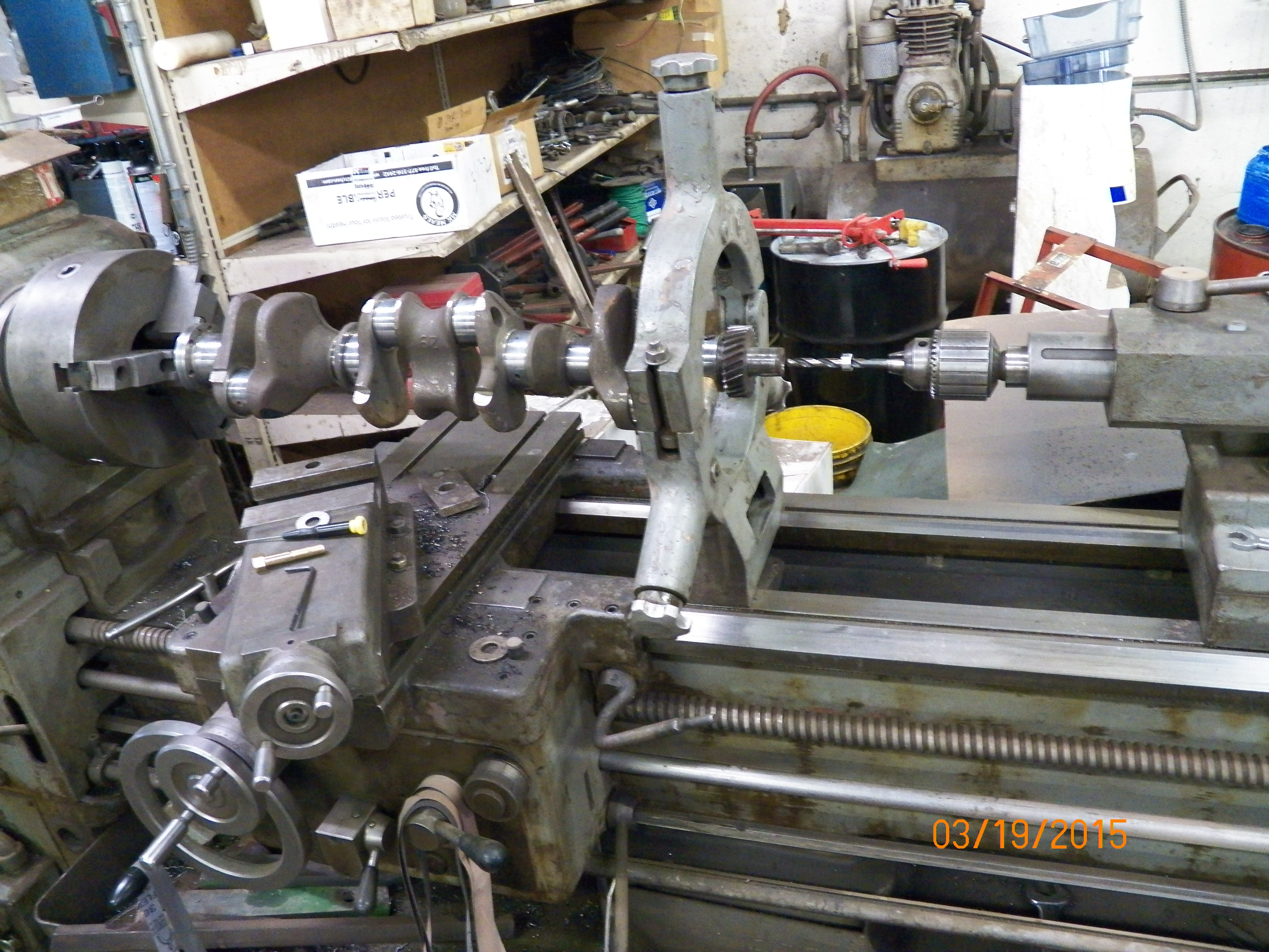
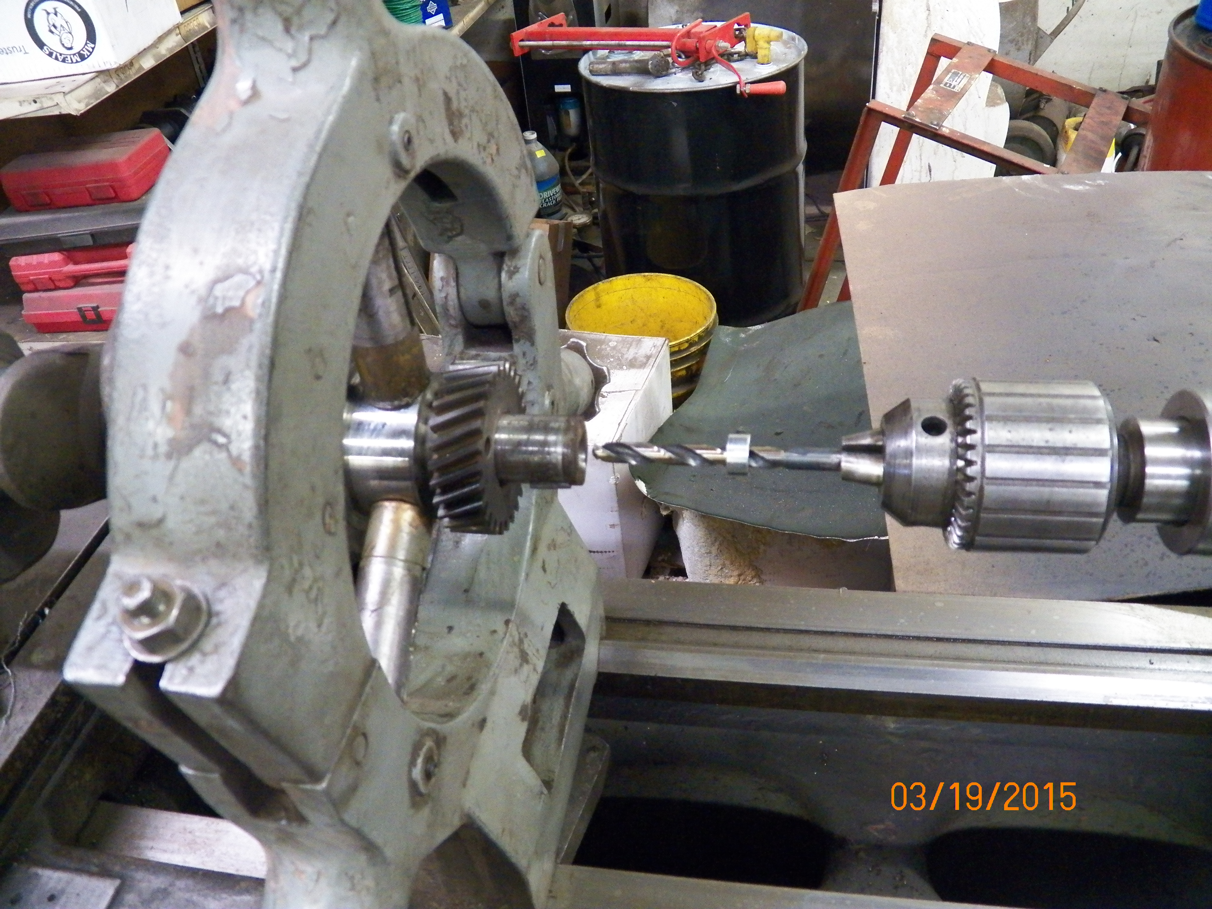
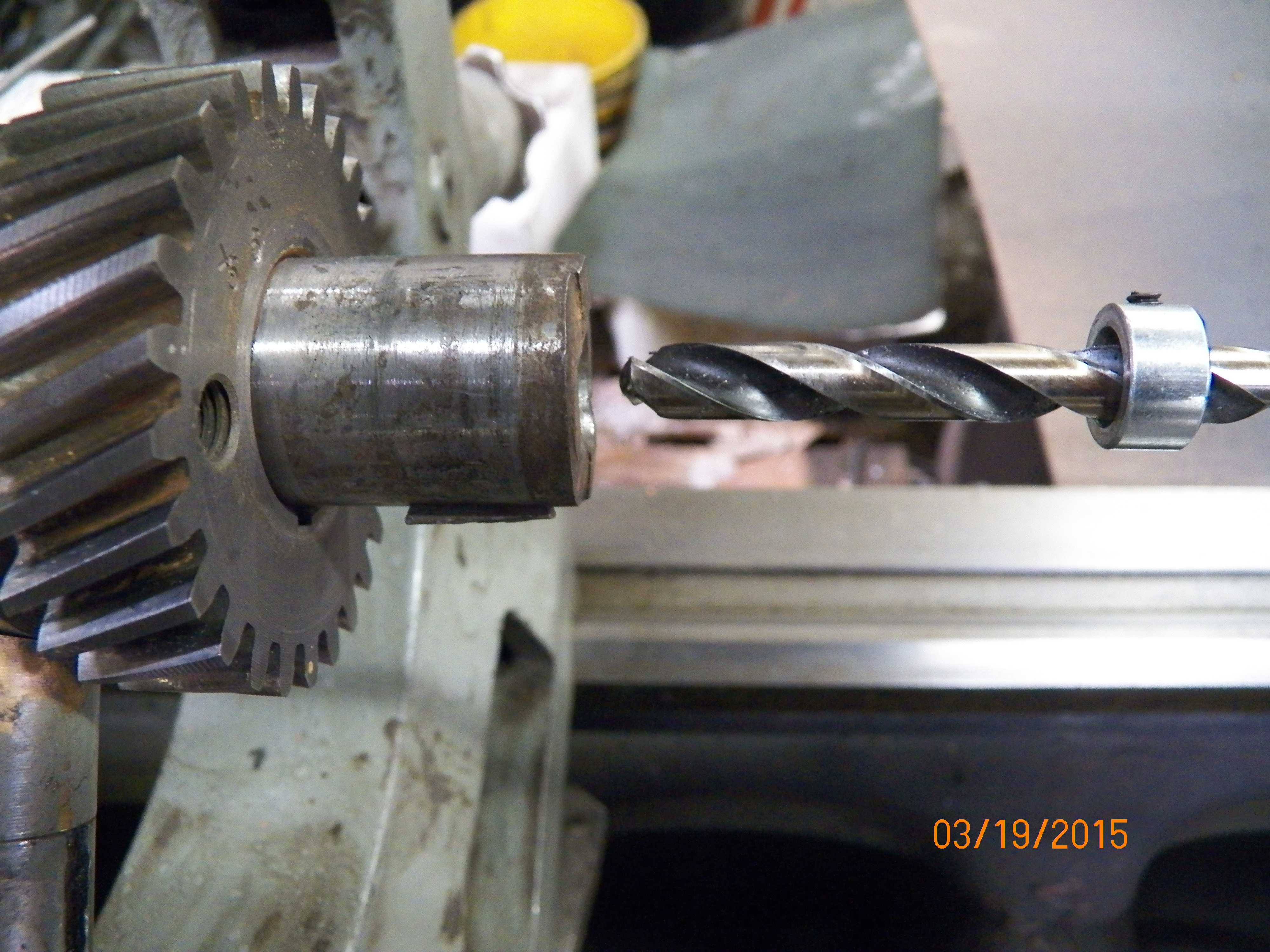
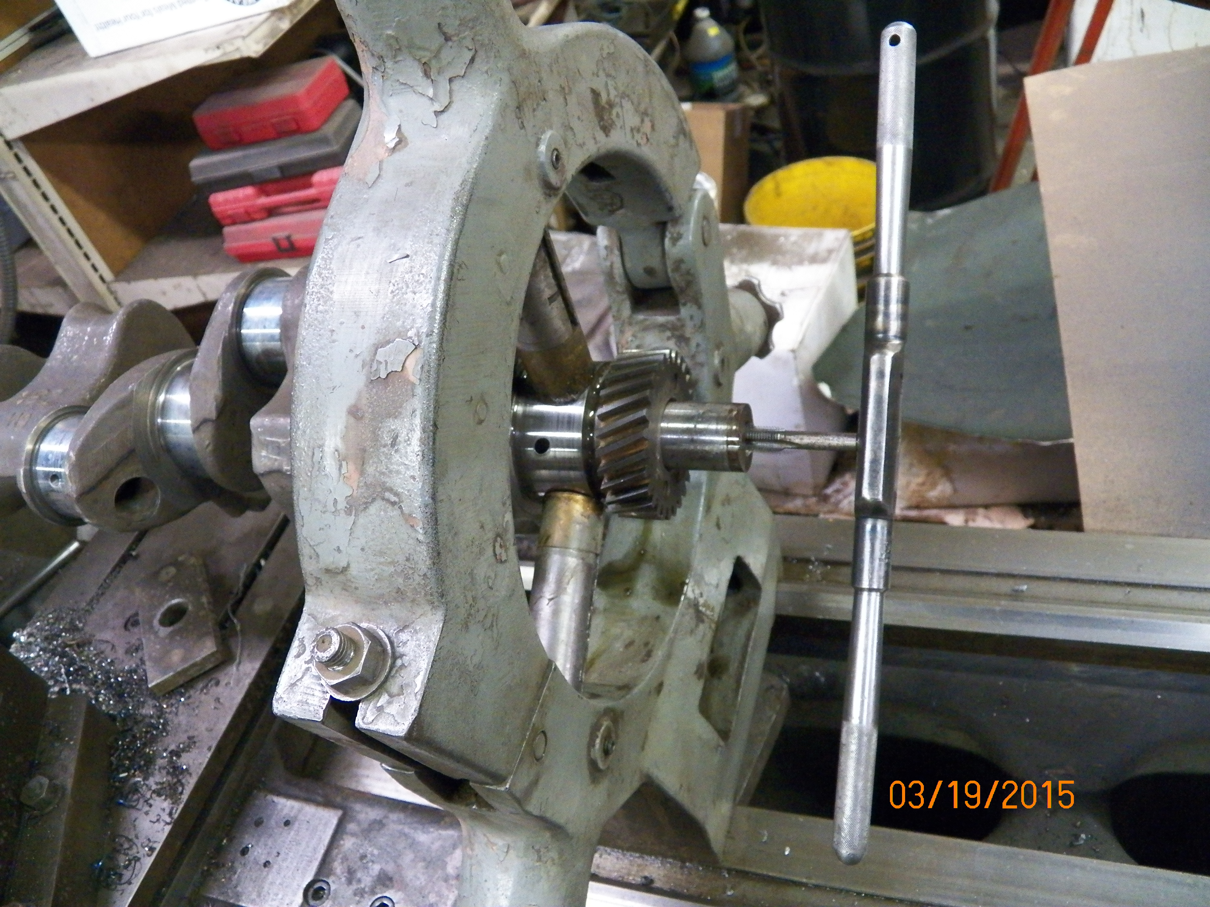
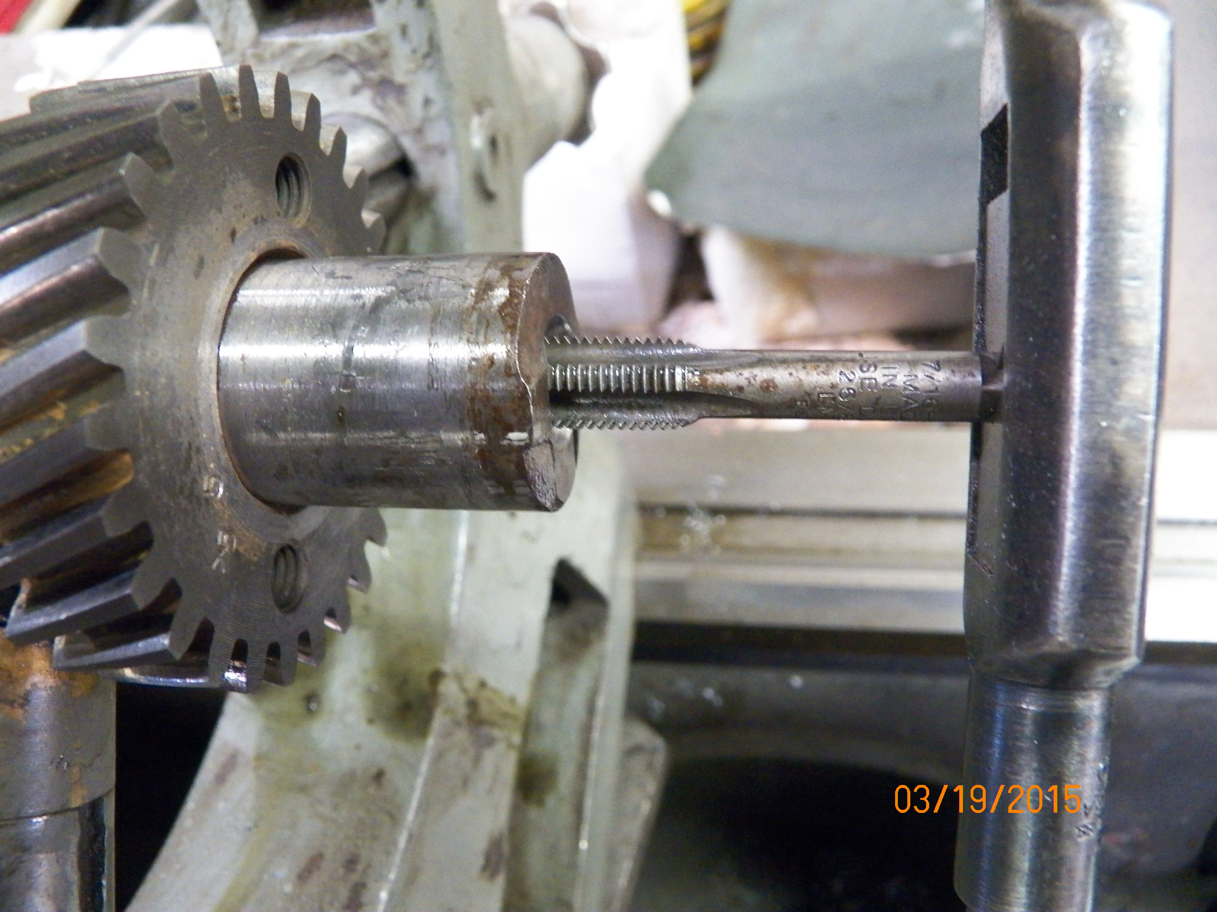
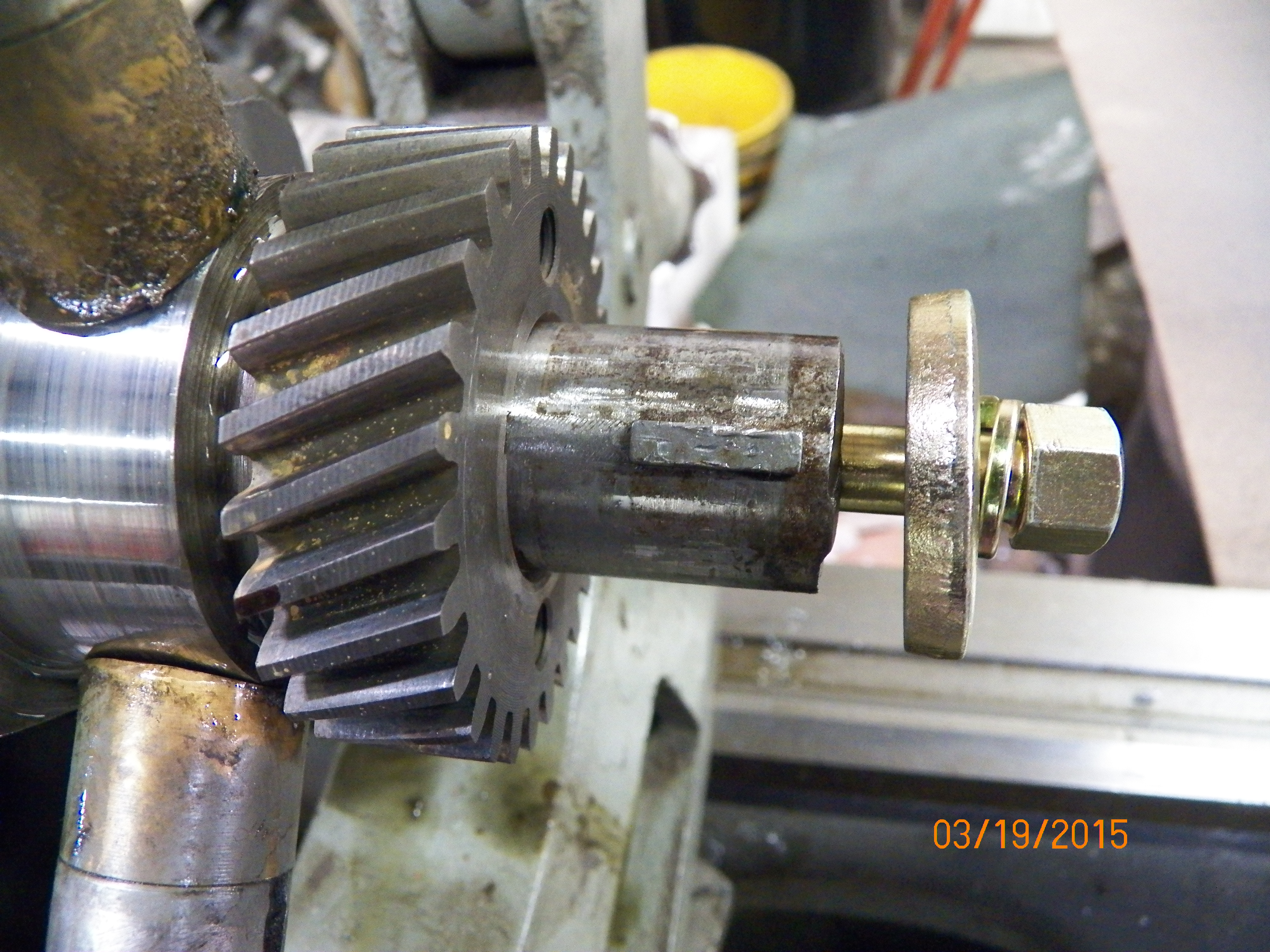
These show the crankshaft being ground to eliminate any elongation of the bearing surfaces. Ended up being .010" on the rods and mains. Making sure your crankshaft isn't out of round will ensure smoother engine operation.
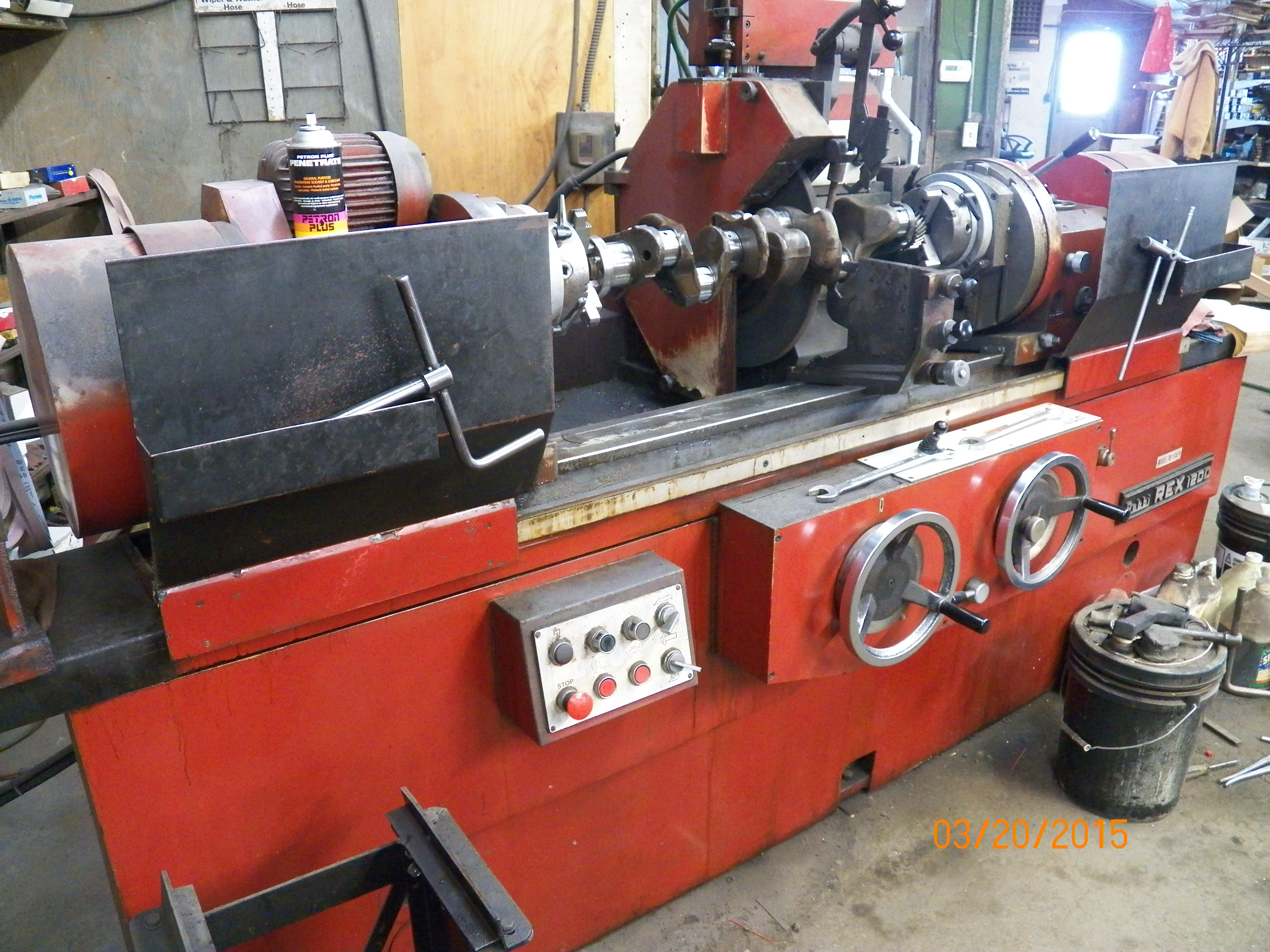

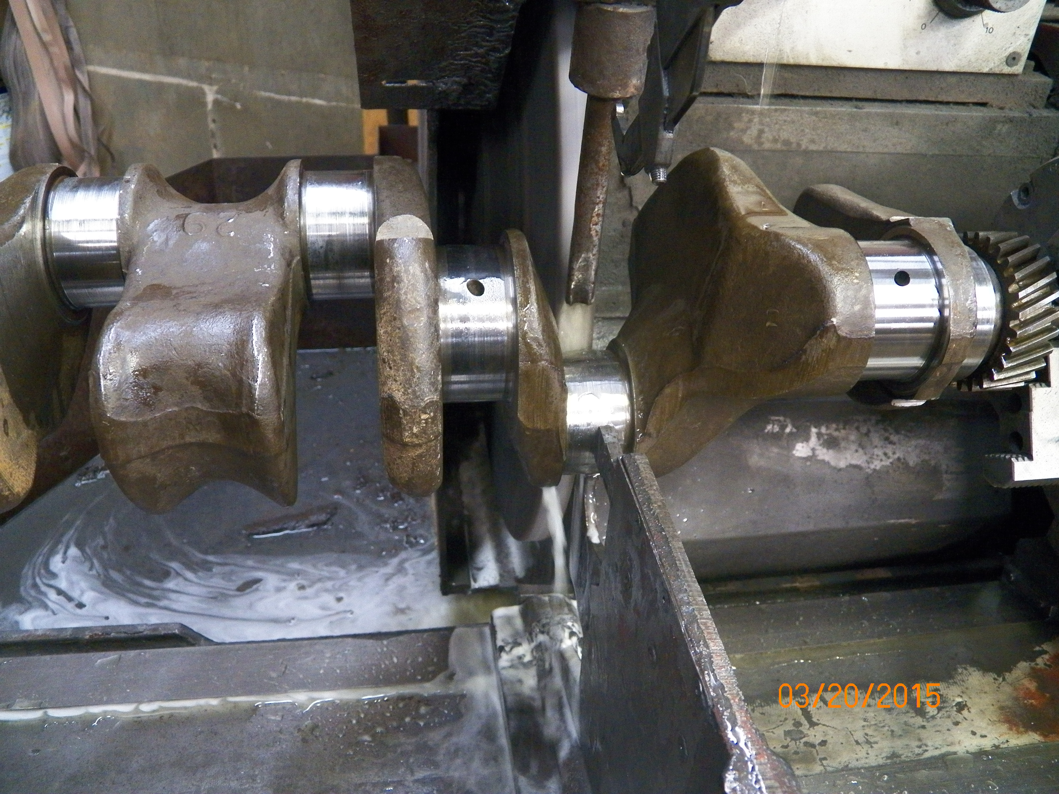
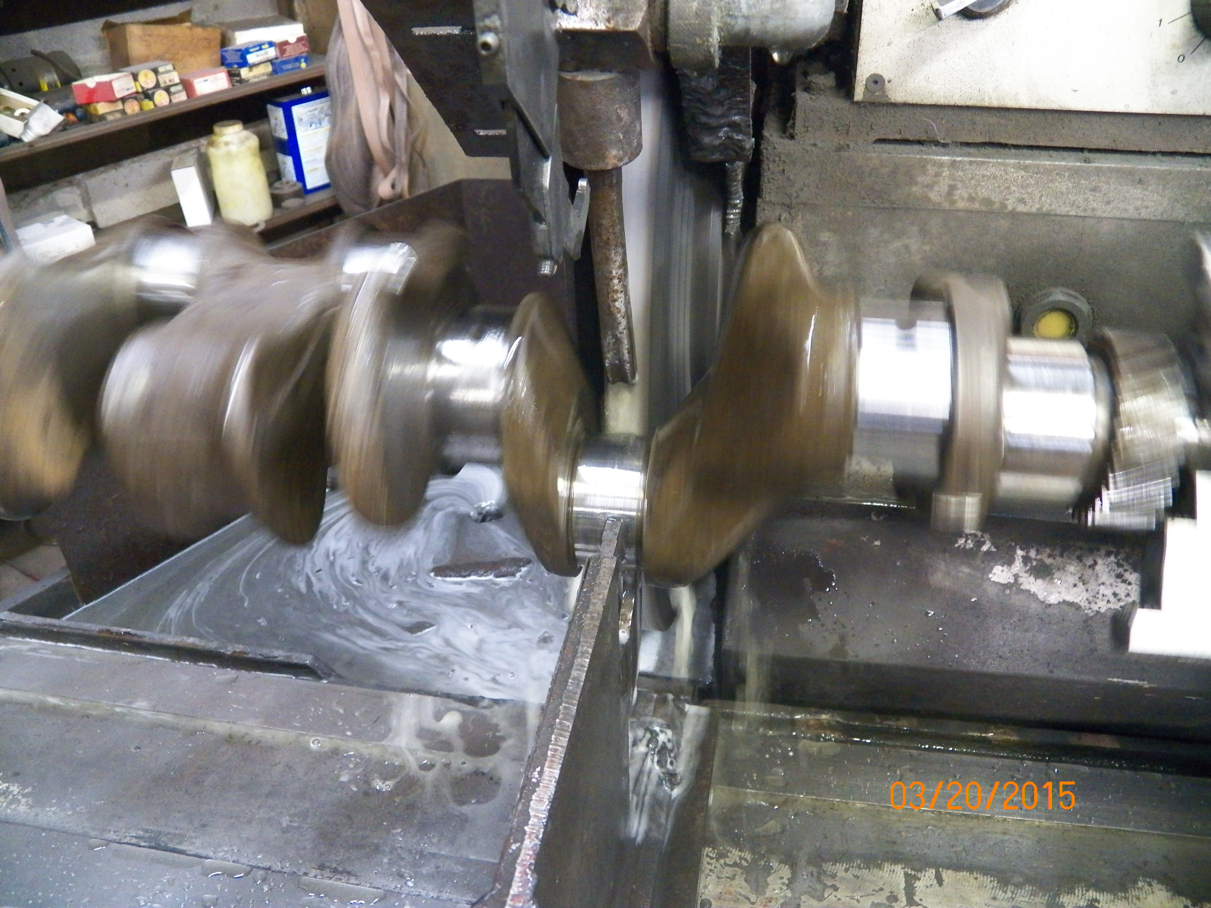

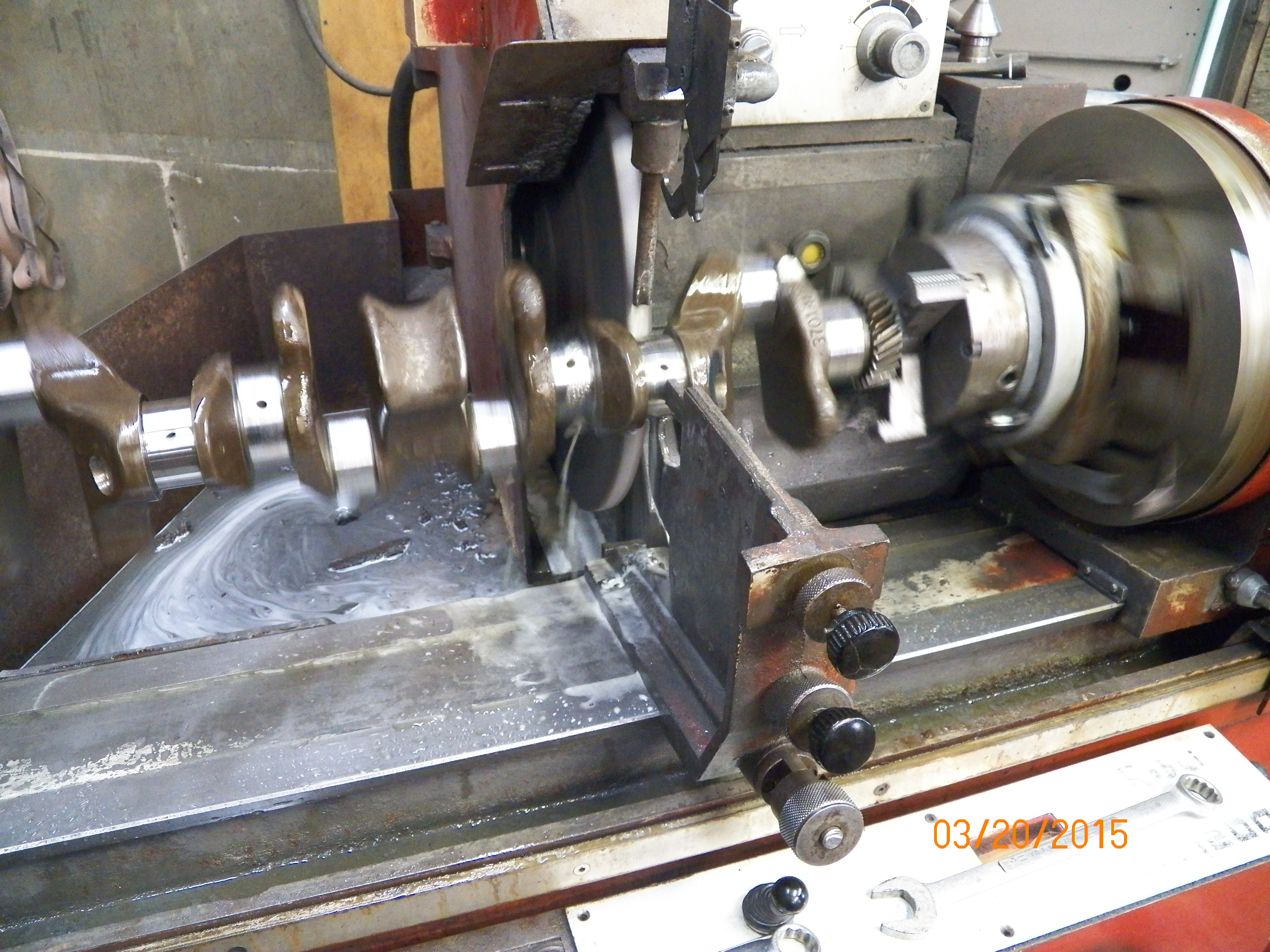
Below is the Head being resurfaced. This is a more of a check than anything to begin with. They place the head on a very flat surface and run the stone over it little by little until it barely meets the surface. If it is not warped in any way, it will create a uniformly smooth clean surface. If not, the millstone will work it until it is. This is just one of the tests to make sure the head can be used again. It passed!

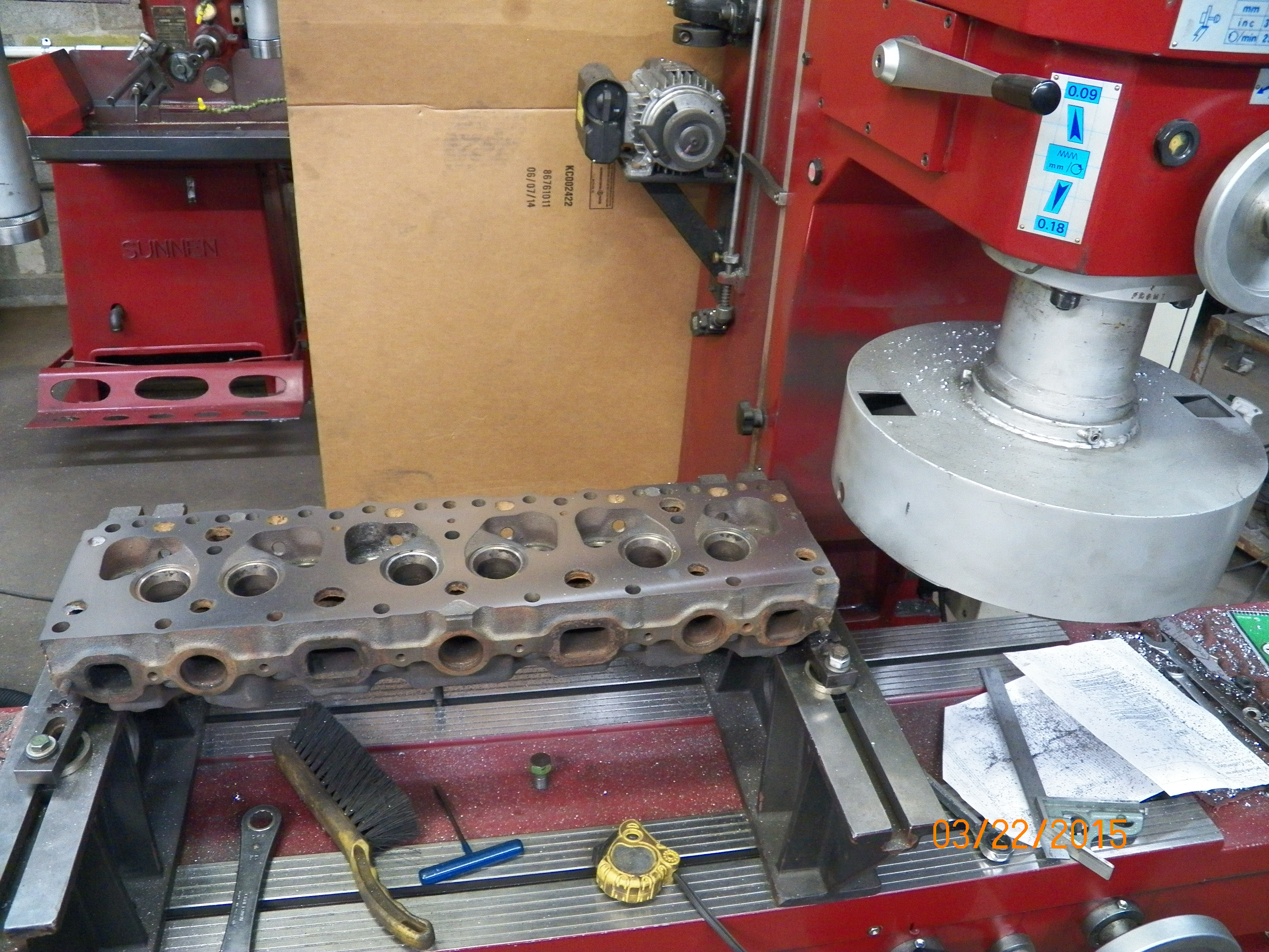
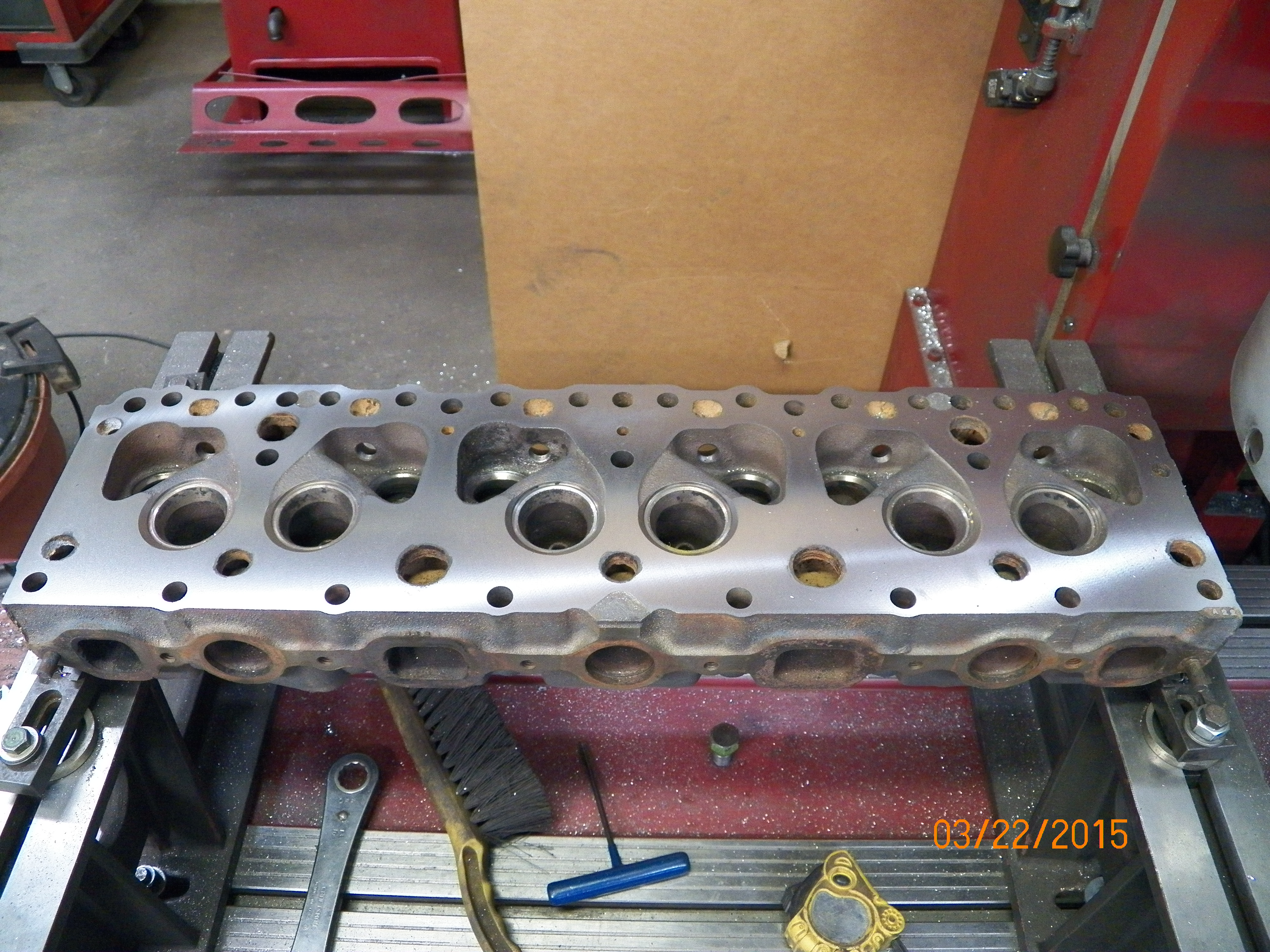
Below is the Head being pressure checked. This is a test to make sure no pinholes or anomalies we can't see are present. It passed! We then proceeded to set up the Valve Seat Cutter to match the Valves profile. This tool cuts all three seat angles at the same time with a fixed cutter. Not very much is taken off, just enough to ensure perfect seating of the Valves.
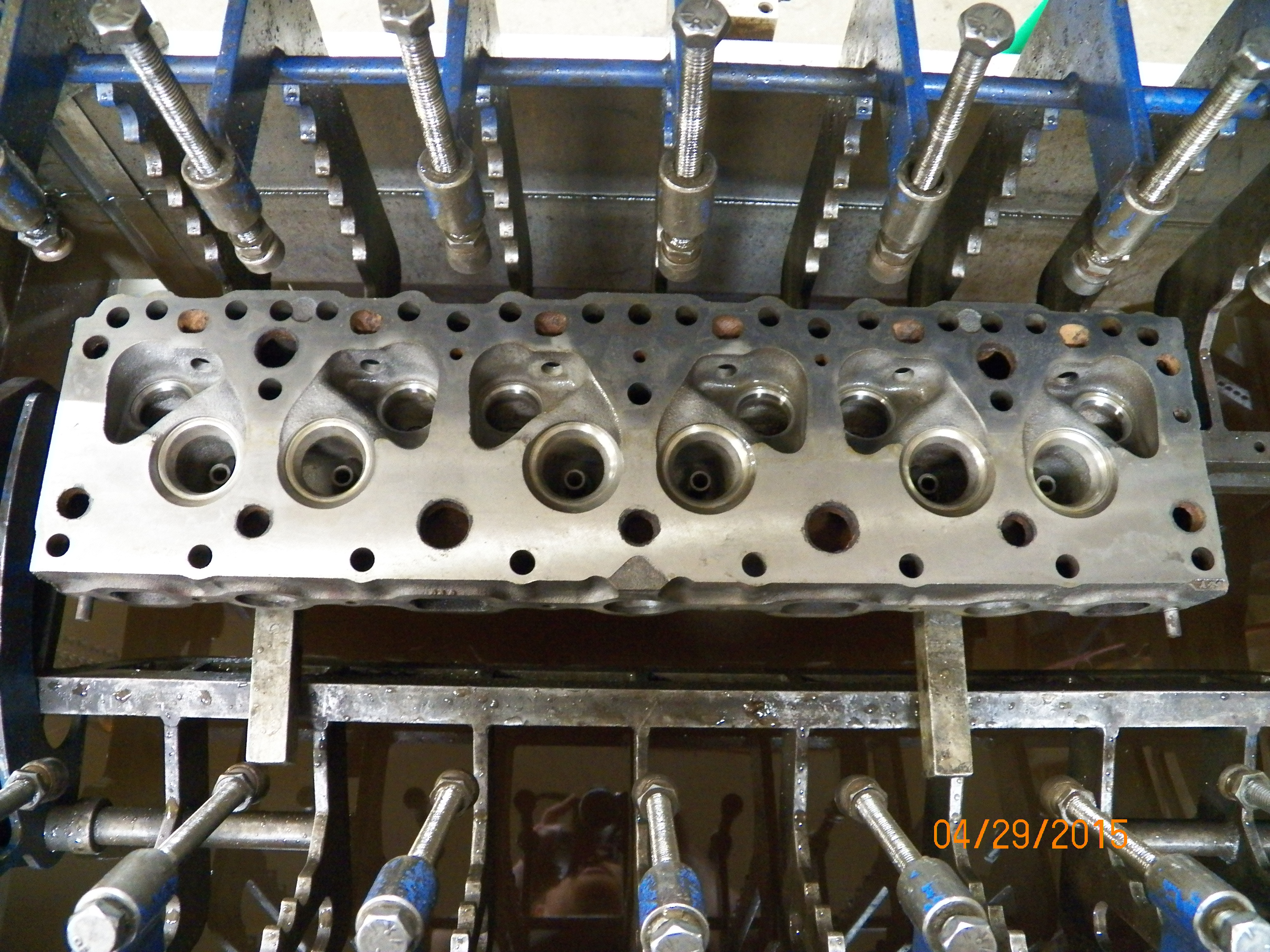
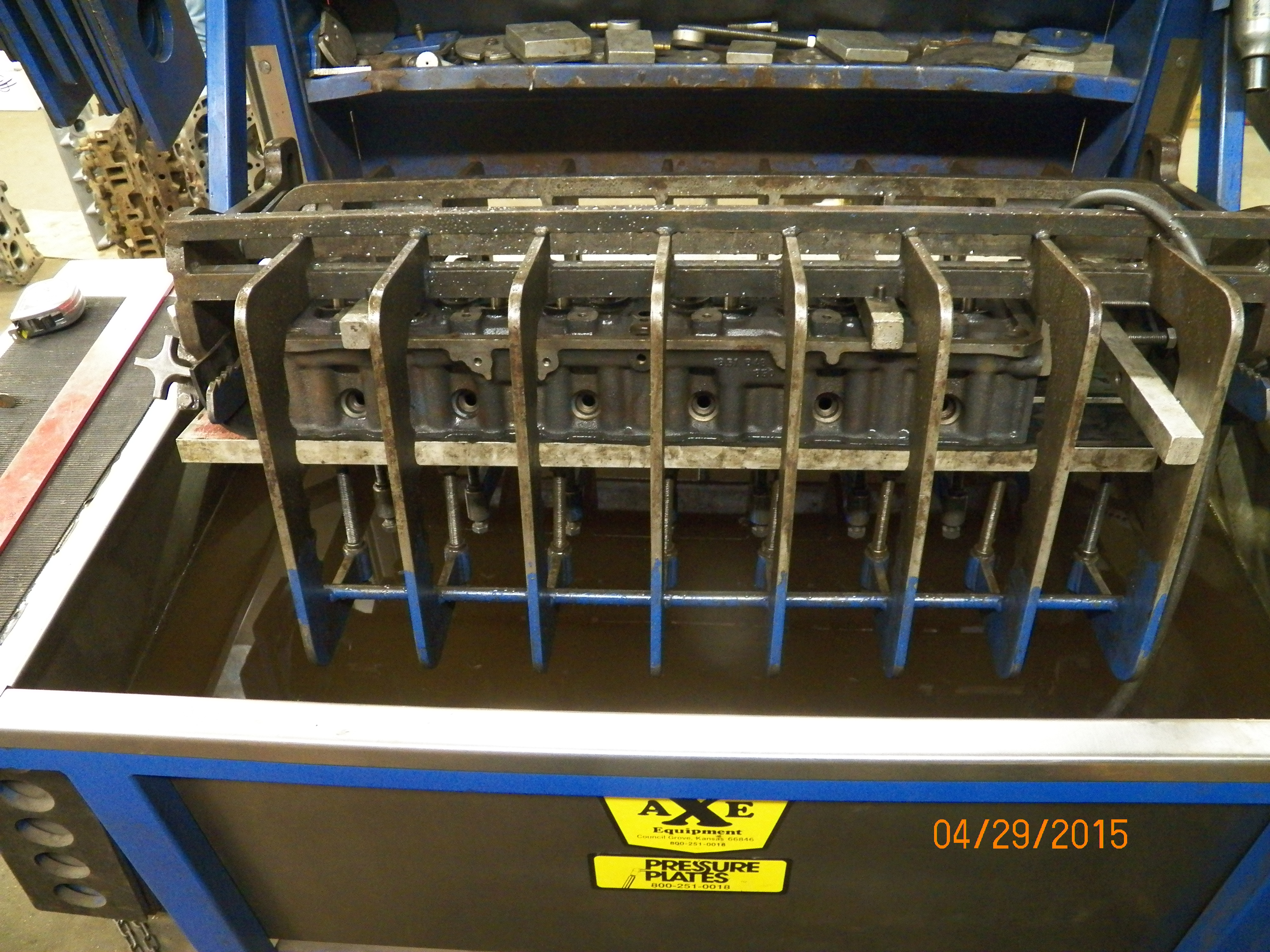
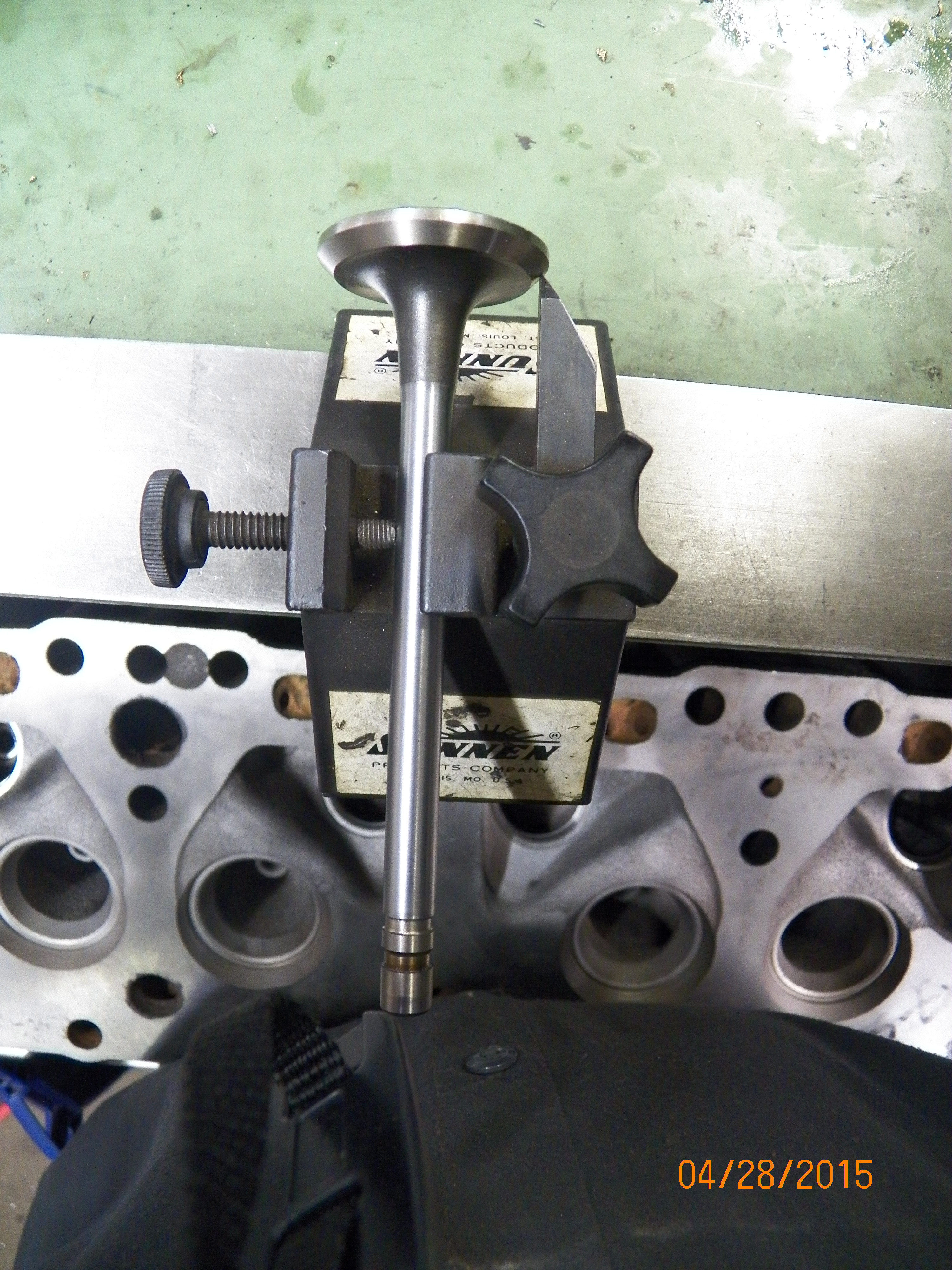

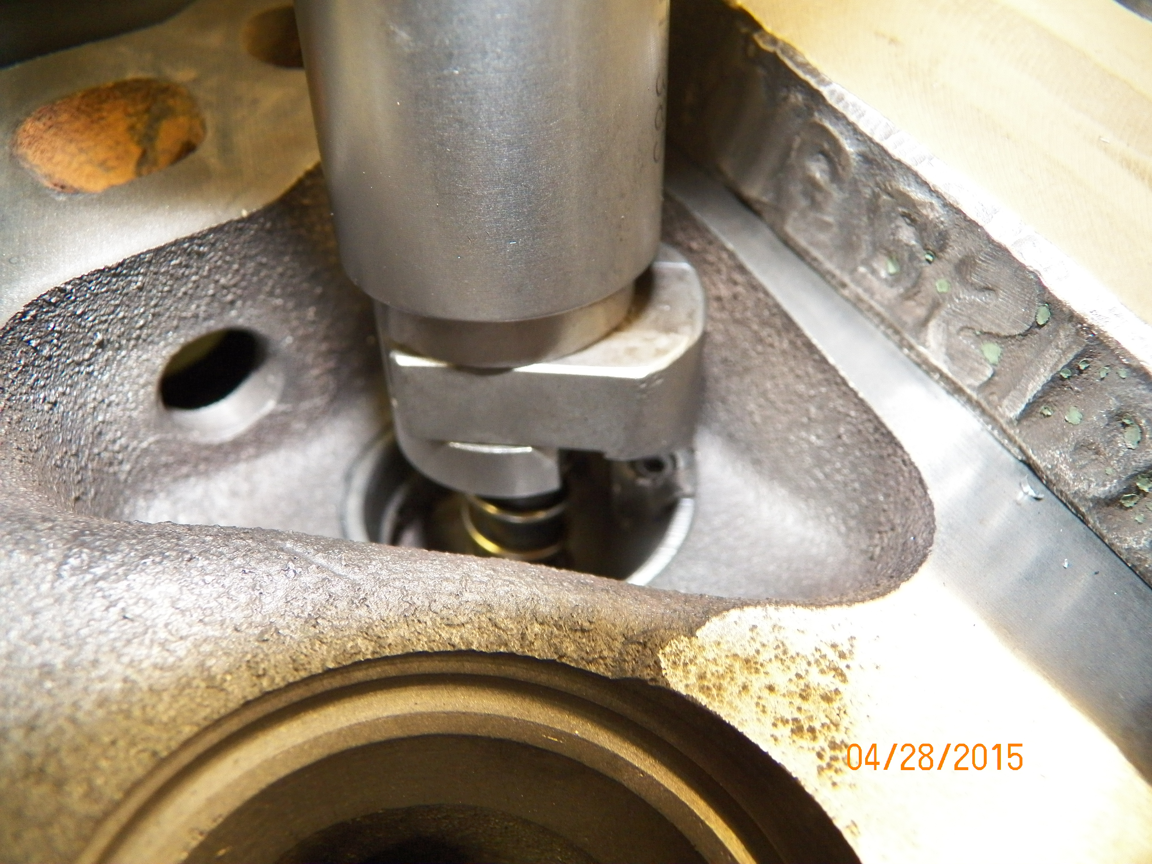
It may also be of interest to know the displacement numbers for the different over-bore sizes. This information is easily ascertained by
working through a basic formula using the numbers in the chart above. The formula is:
|
|
|
|
|
|
|
|
|
|
|
|
|
|
|
|
|
|
|
|
|
|
|
|
|
|
|
|
|
|
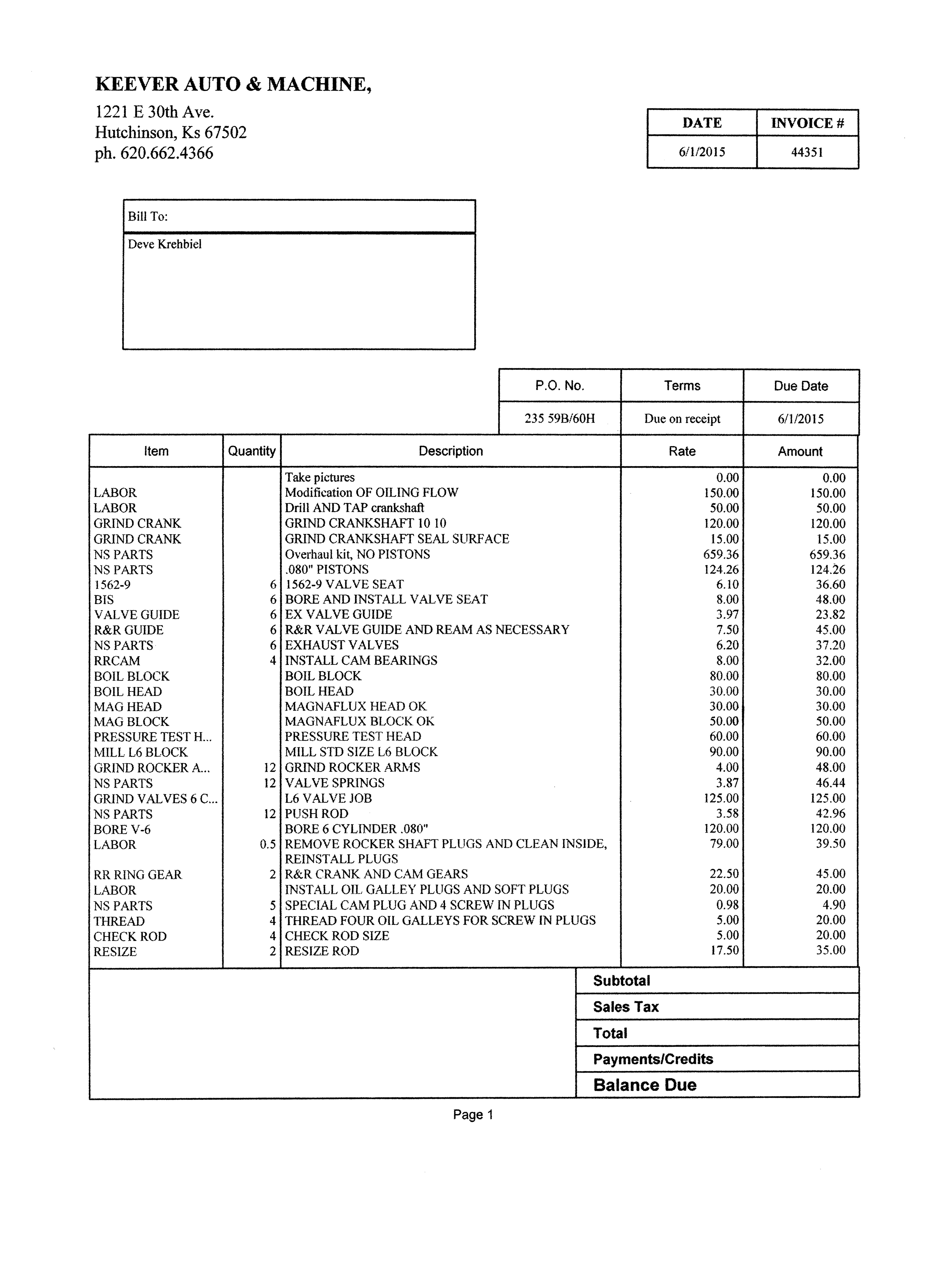
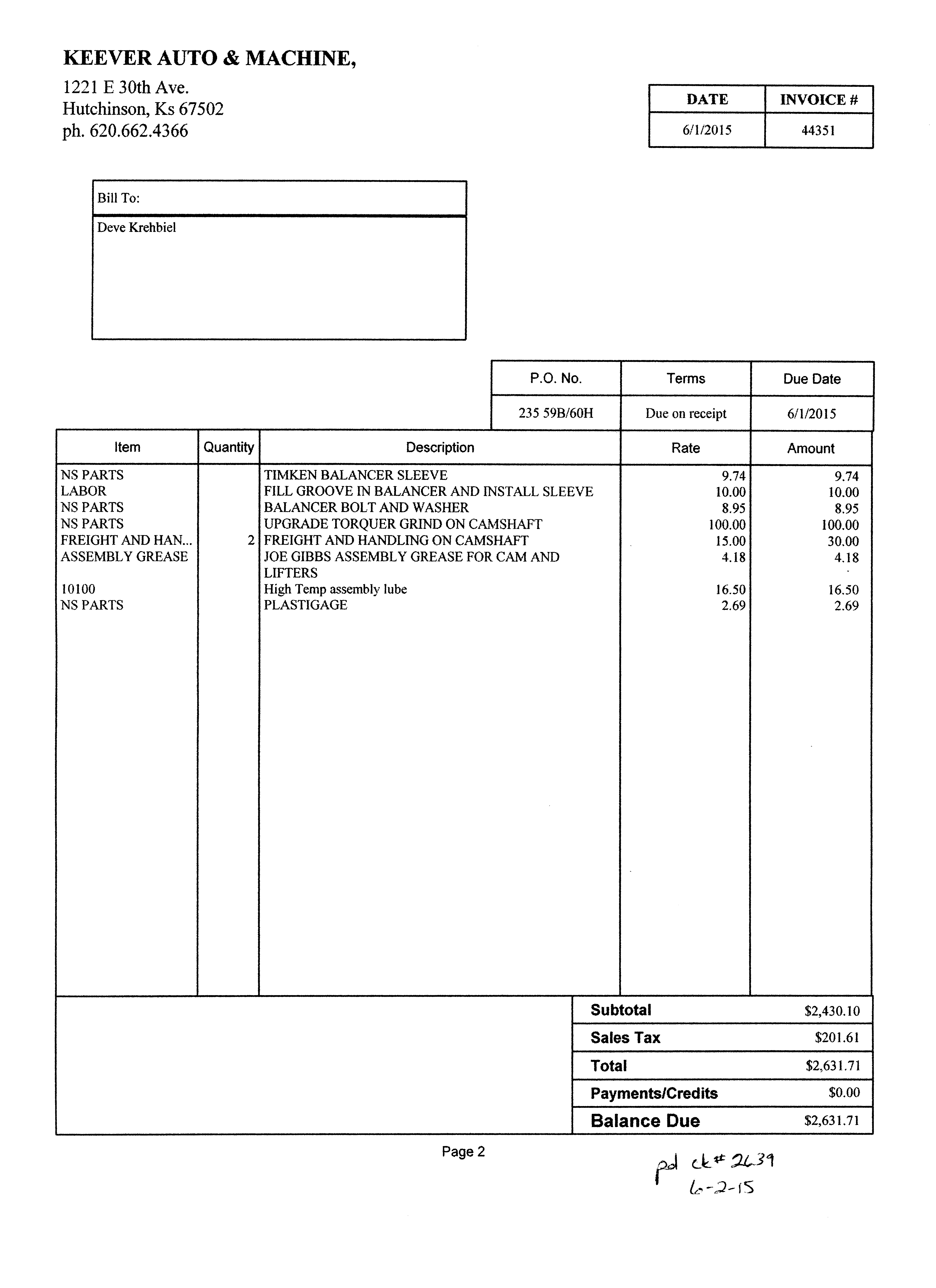
I want to show you the actual cost of the machine work so you understand clearly where you can save money or what costs what. This particular engine is machined to show you what is possible, so there are cost cutting measures you can take. For example, I wanted all of the oil to be filtered so they machined it for full flow filtering. I also don't like those little freeze plugs at the ends of the oil galleys, so I had them tap them and put in actual Allen type screw-in plugs. Also I wanted a bolt to hold the Harmonic Balancer in, so they machined the crank for that. I also had the Cam sent off and reground for just a little better low-end torque. This stuff adds up, but this is the total bill in detail.
With the engine back from the machine shop, we can prepare for our part of the rebuild. Two things needed right away are a proper Engine Stand and a Engine Hoist. While you are at it, get folding ones so they don't consume all of your shops floor space as listed in the Tools List. You will want to hoist the engine out of your vehicle and ready it for the engine stand. Do not cheap out on the engine stand! This is because these 6 cylinders are very long and top heavy and it's just unsafe to assemble your engine on an unstable platform. Take seriously all safety precautions.
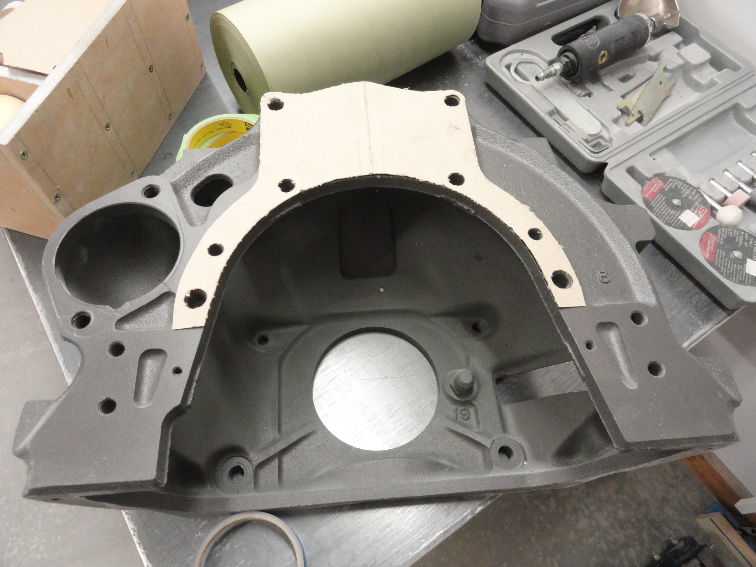
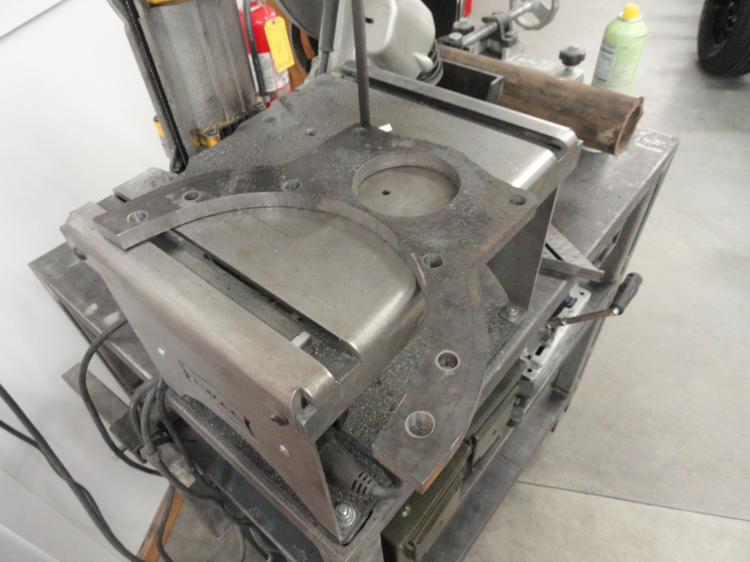
This is where I took the opportunity to end once and for all the fuss concerning making a generic engine stand work properly with our precious inline six. I have done this for years the hard way, so I am going to spend a few days working on something I think will end this misery once and for all. The problem is in connecting the engine to a generic stand. In this case it's the Harbor Freight 2000 pound Engine Stand. It has 6 wheels, fold-able for easy storage, and is made very stout believe it or not. The plan is to re-engineer the head so that it bolts up perfectly to our engine. Start by using the Bell Housing for the template. It's much easier to just use what is already there. Use a small ball peen hammer and some 11x17 chipboard and lightly tap around the indentions and holes until it just falls away. I then added to the outside of the template 1/4 inch to the 'wings' to give that thin area more strength and rigidity. To do this, I just moved the template over 1/4" and traced the 1/2" Plate to accommodate the new size. A piece of 10 x 12 inch by 1/2" plate steel will do nicely.
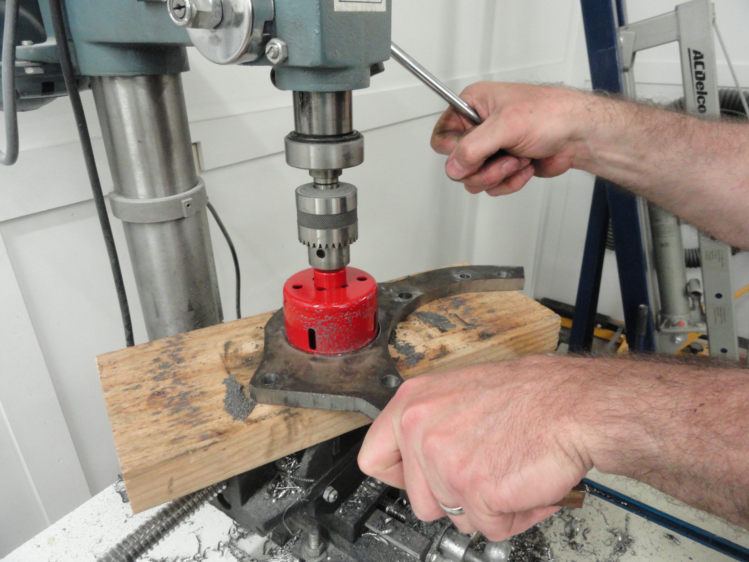
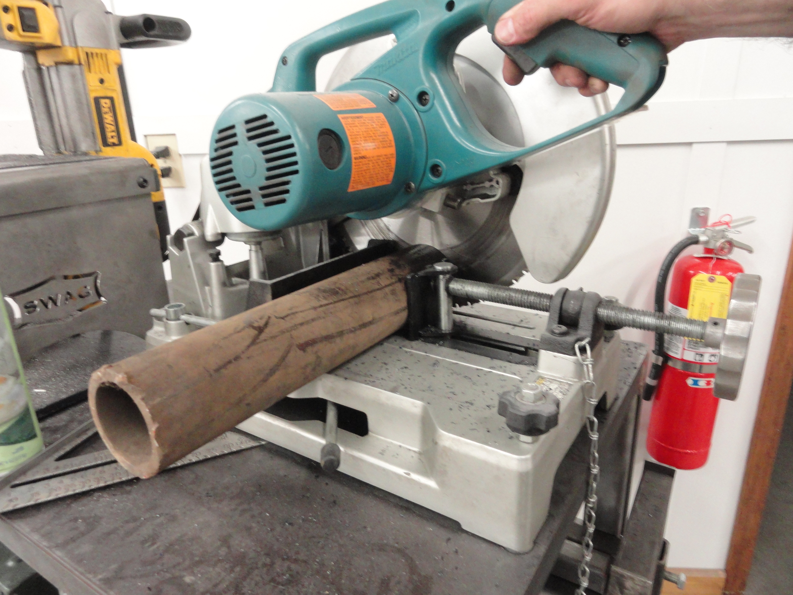
I decided on a piece of round DOM steel tubing for the pivot piece. The HF Stand that I got uses a 3 inch pipe, so I cut it out of a 3 inch DOM with 5/16" walls. This is much stouter than the original one supplied with the stand. I won't bore you with pictures of the drilling process because that is pretty standard. The six mounting holes in the flat plate are 1/2" holes. The two that are used to get around the mounting pegs are 7/16". The round stock was drilled evenly around it for the stop pin and they are also 1/2". The holes adjacent to each other for the handle are 7/8". The stop pin holes (8 of them) are placed 2-3/4" from the plate end. If you have never had the pleasure of cutting a 3 inch hole out of 1/2" Plate Steel with a bi-metal hole saw, now is your chance! I want the tubing to go all the way through the plate. This way we can get a good weld on the front and the back. Can't have this thing falling off!

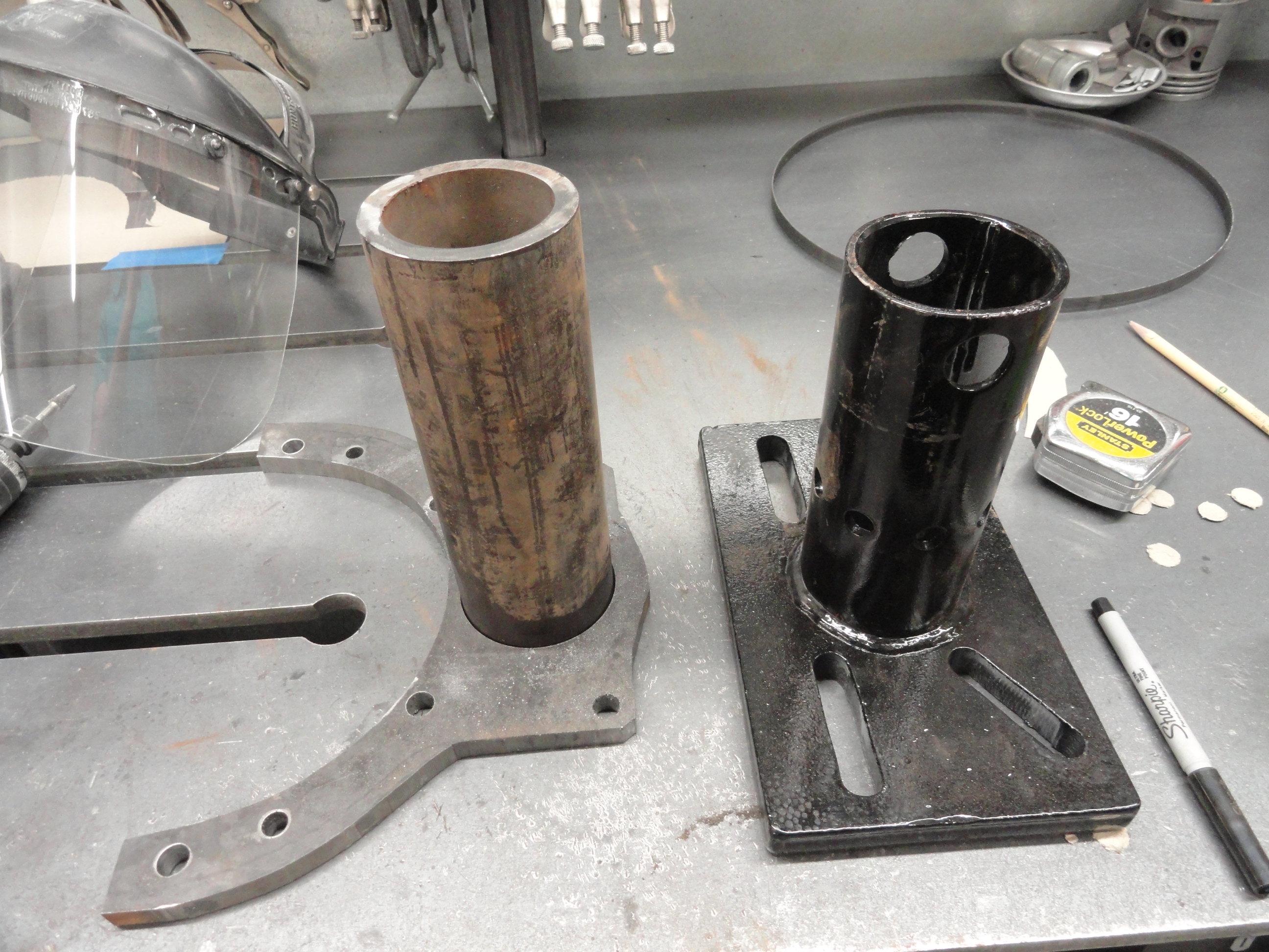
Before welding them together, bevel the edge all the way around the tubing to give good room for the weld. This is very important! I beveled a little over half of the thickness of the tube. I then sandblasted everything and then cleaned both pieces off with metal prep cleaner. I want these welds to be really strong. I used a 220 welder on its hottest setting and increased the wire speed. This gave me really good penetration. Finally, test fit and then give it a nice shiny coat of paint. Now we can get to the business at hand!
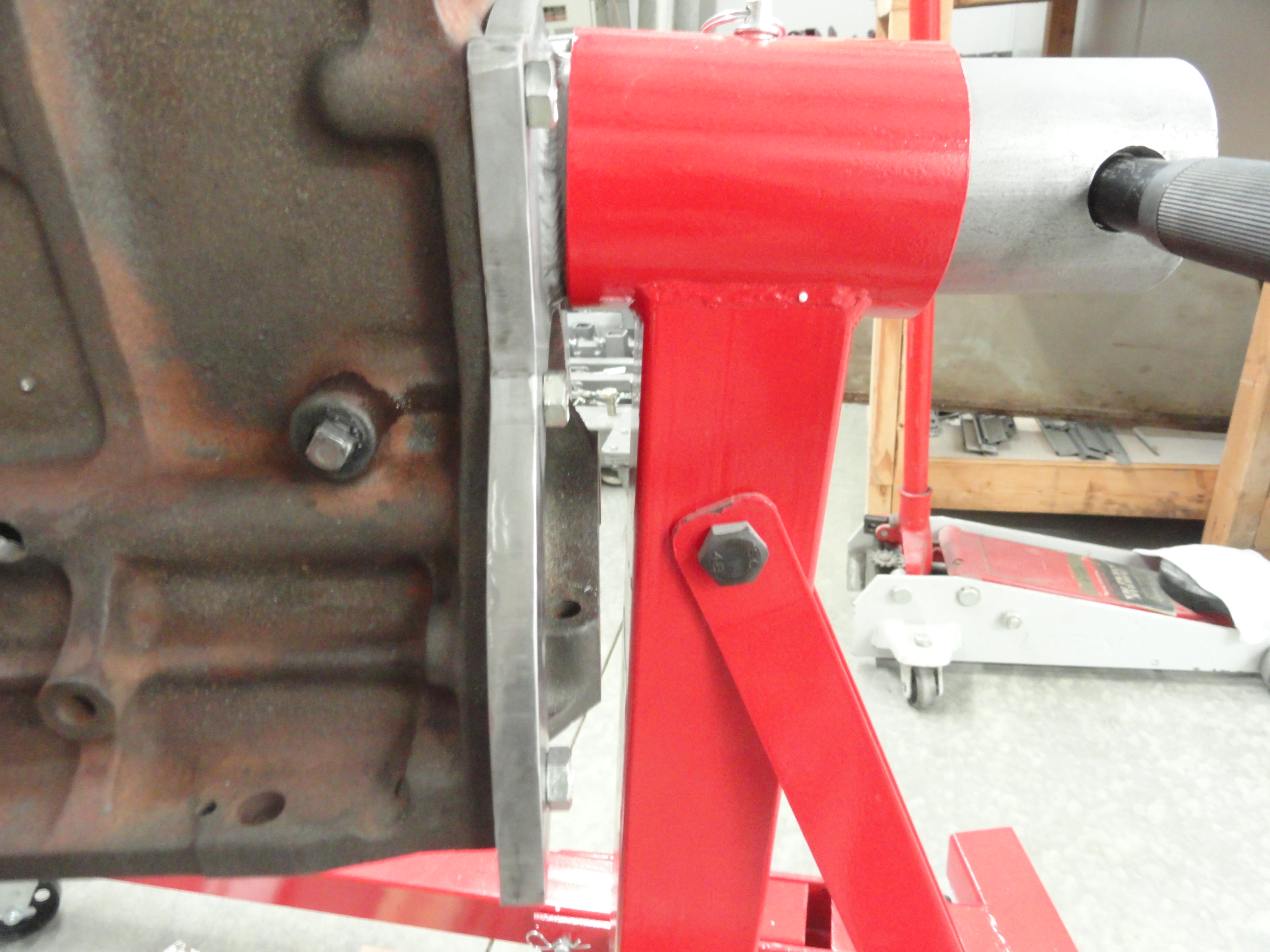

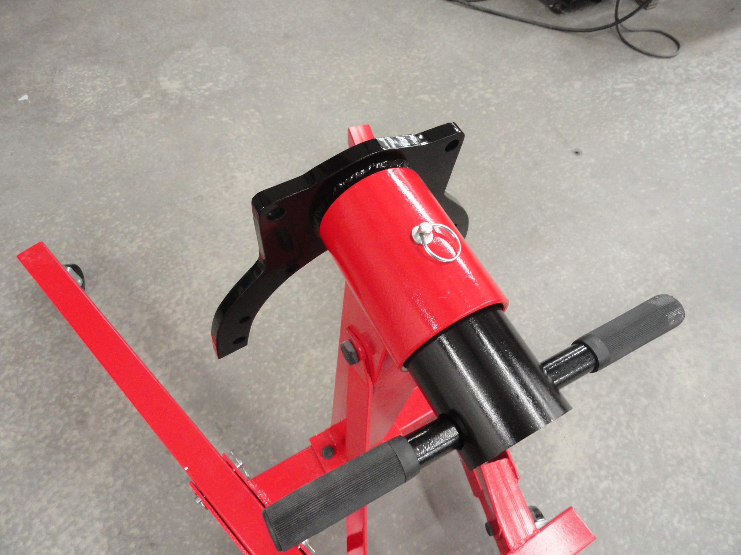
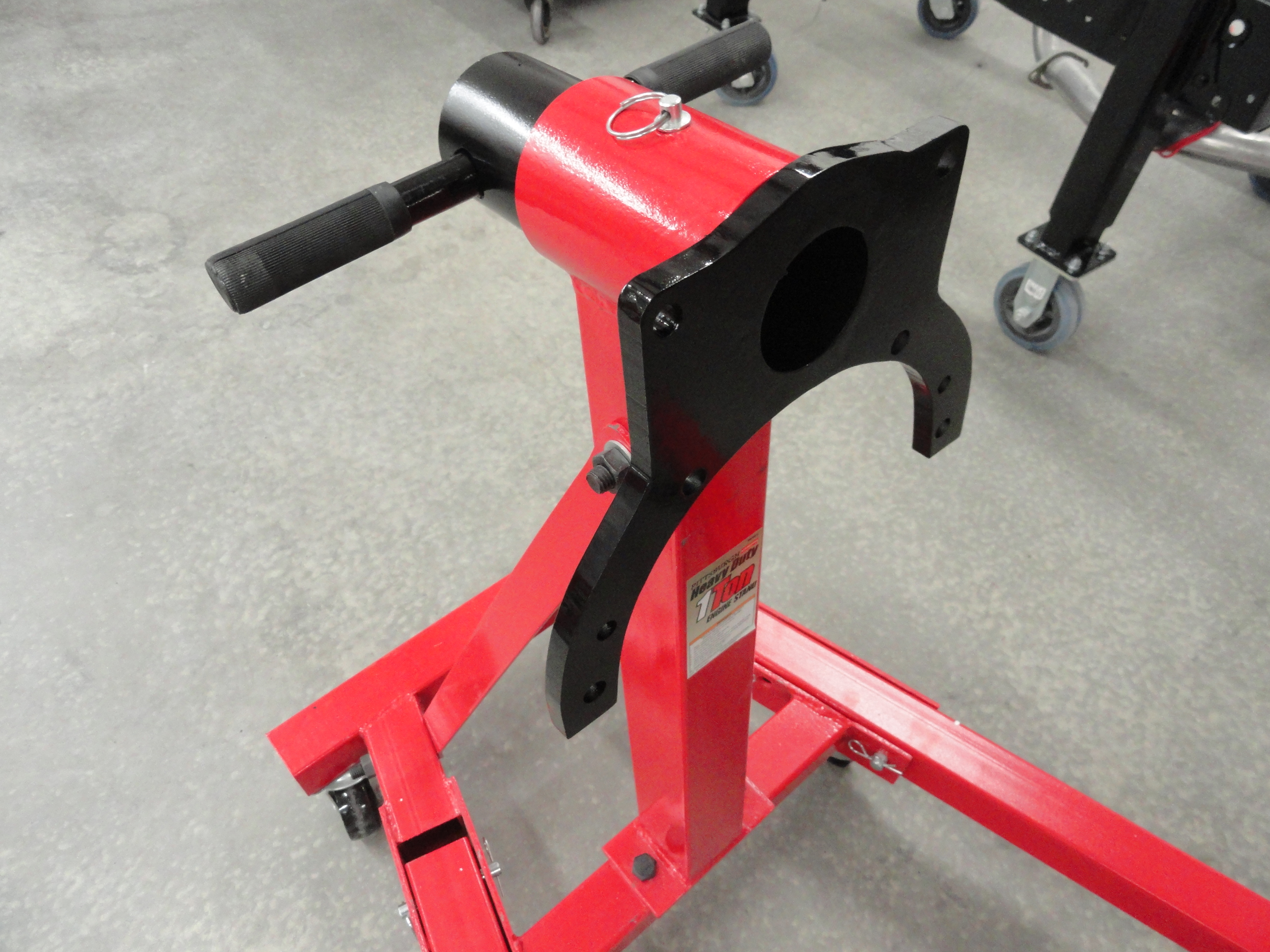
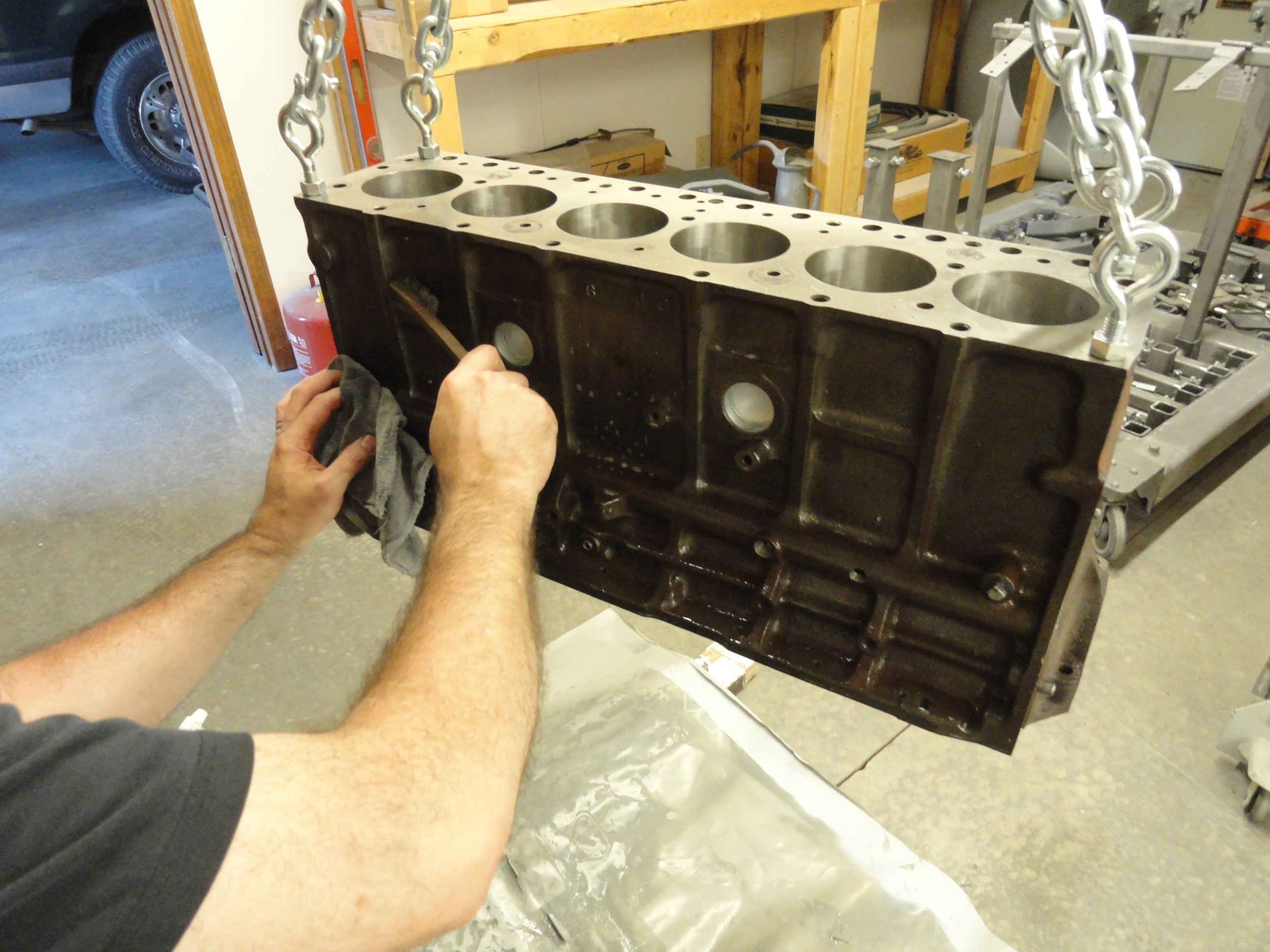
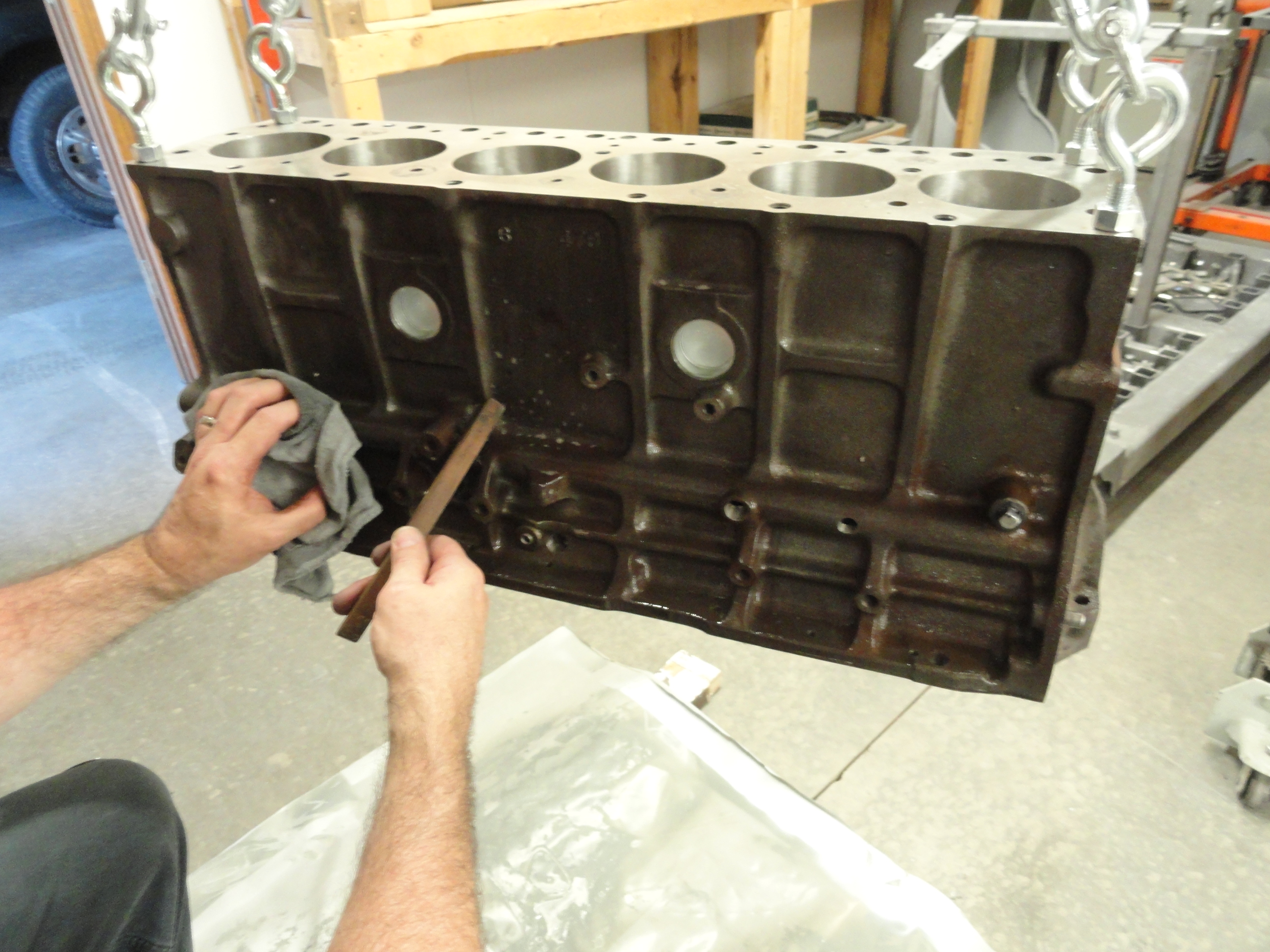
The engine is for the most part clean when it comes back since it has been boiled out, however, machine shops are dirty places and we must clean the entire outside surface of the block and the head so that our engine paint will stick properly. I use a wire brush, shop rag and Lacquer Thinner to start with, then switch to PPG DX-330 Metal Prep Cleaner. It's time consuming but I did find a few places that needed extra attention. Another thing I like to do is take a rotary grinder and grind off any sand casting that looks like it could come off in the wrong place. One of those places was the fuel pump cutout and then along the oil galley areas.
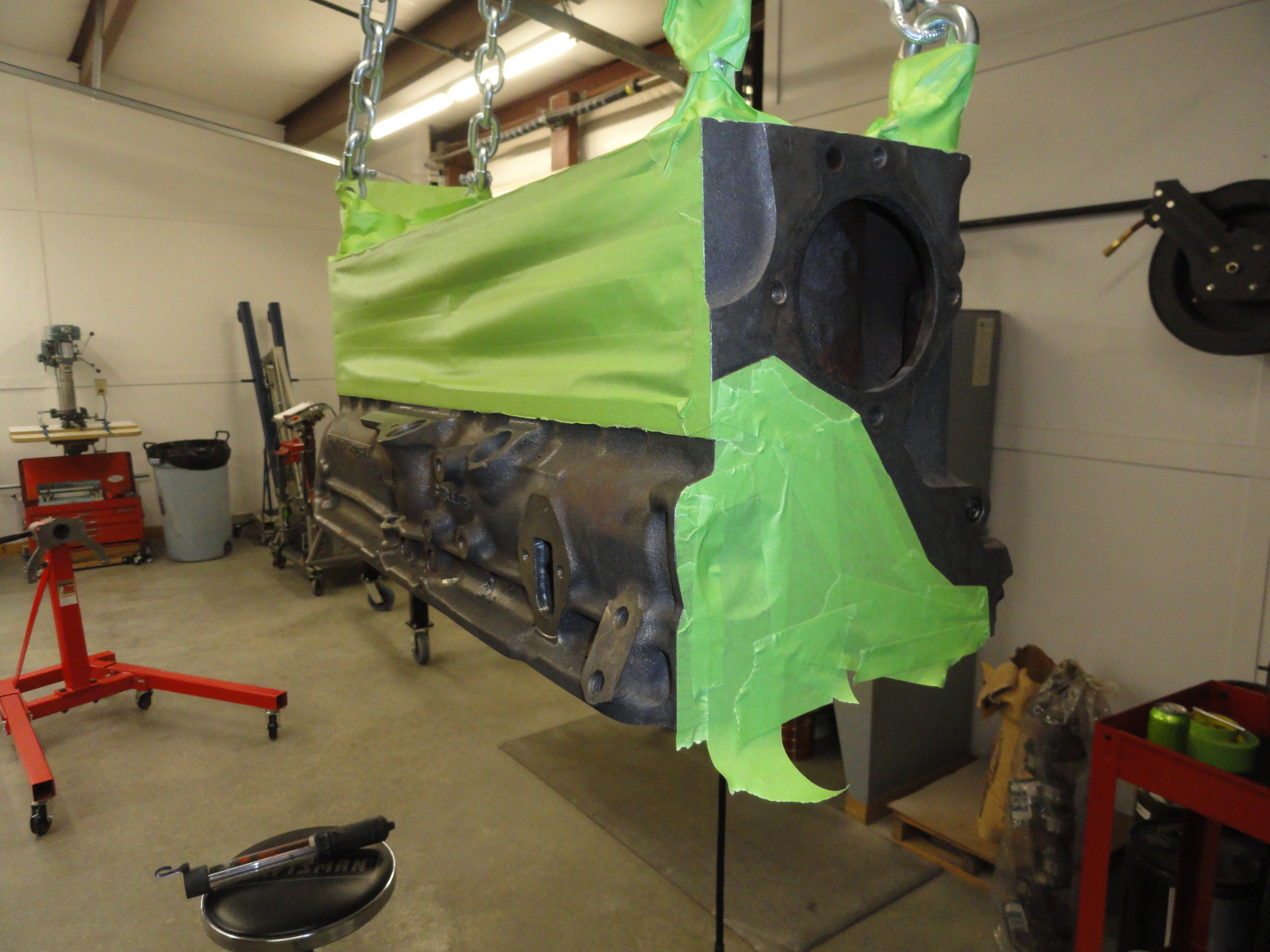

The next step is to tape it up so we don't have alot of overspray in unwanted areas. I realize you can just walk around with a piece of cardboard in your hand while painting and shield the areas you do not want overspray, but I just prefer it this way. After two good coats of Duplicolor 7272 Gray I also sprayed a few' coats of clear coat on it as well. Both of these products are 500 degree paint, so it should work nicely. Another item that you will want to hit with paint is the harmonic balancer. I like to paint the pulley part black and the rest of it engine color.
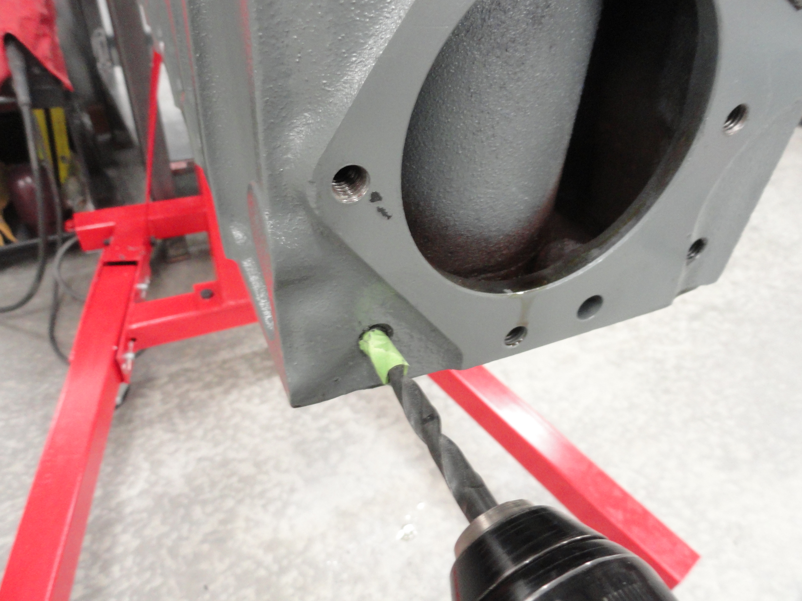
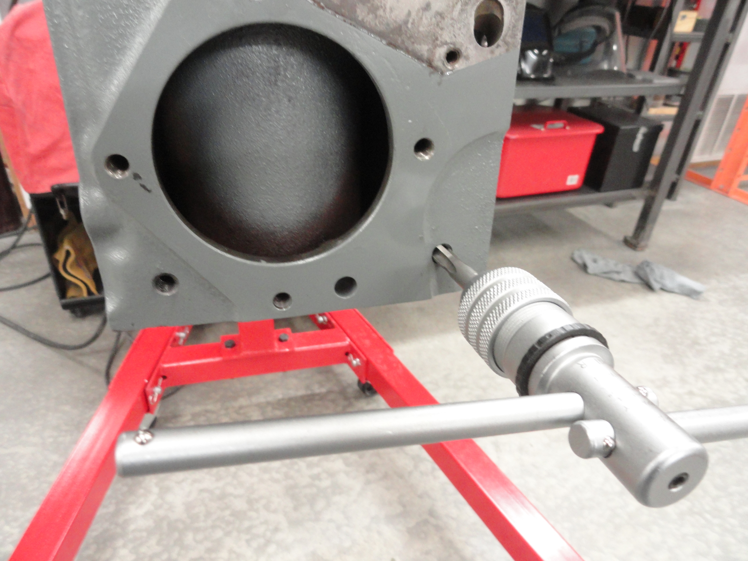
Any machine work that is still left to do, or any process that could introduce metal shavings or contaminants should be done now, prior to assembly. In this case, I am using my friend Dave Folsom's Water Pump Adapter Plate to raise the Waterpump to the center of the Radiator. Most people do not realize how the old original 216 had its fan directly in the center of the radiator, but the newer style 235 has it considerably lower. This fixes that once and for all. Following his instruction carefully, I drilled two 5/16" holes 3/4" deep which is the correct hole size to then tap for 3/8-16. Use a flat bottom tap to take full advantage of the 3/4" deep hole. Do not drill ANY deeper especially be careful on the side where the head bolt is close. Blow out all of the metal with air and clean the area thoroughly. There is much more to this modification but this is the machining part. I will discuss how to do that upgrade later in this document.
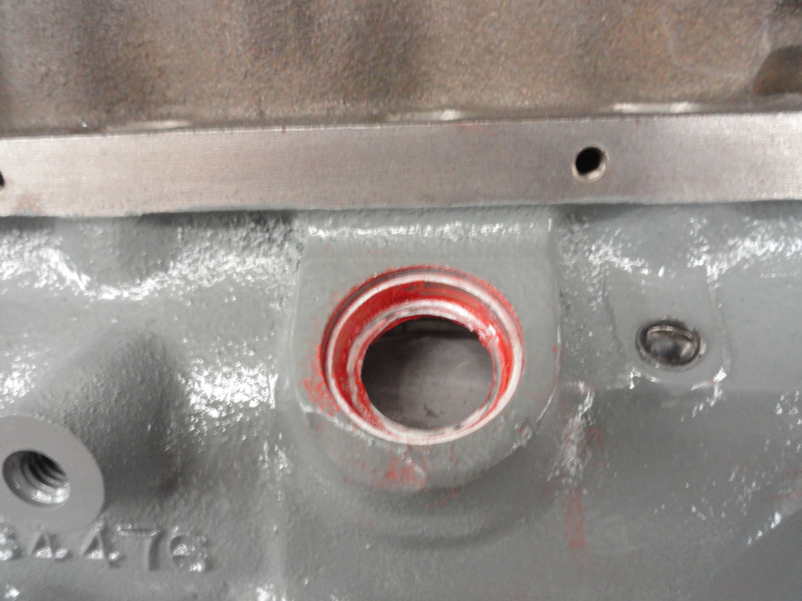
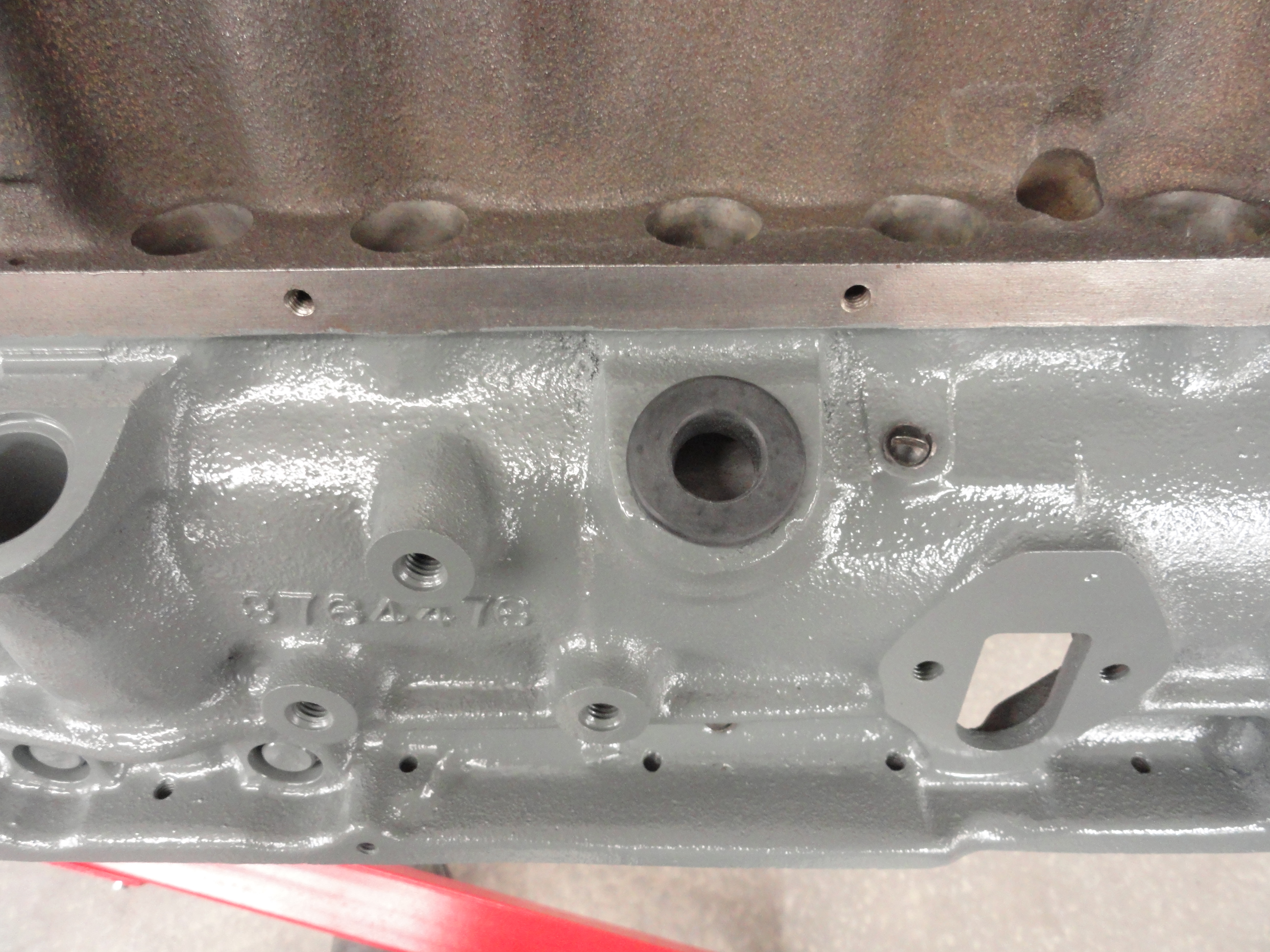
The other thing that I like to do now is put the PCV freeze plug in place. This is a 1-1/4" cup style freeze plug with a 3/4" hole in it. Tap it down below the lip by about 1/32". I use copper gasket sealer to hold the Mr. Gasket No. MRG-6379 grommet in place. The road tube hole is the perfect place for this mod. It even has a nice splash guard on the inside of the block to keep raw oil from getting sucked into the intake. I will do further testing once this engine is together to determine the exact ideal PCV Valve that goes in the hole. Since the ones I am testing are all standard physical size we can do this now. Lastly, install the splash guard on the inside of the block. It is held in my two sheet metal screws with thin flat washers.

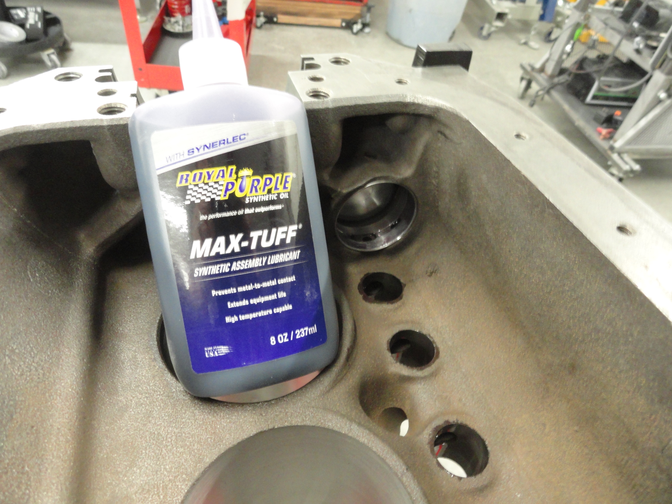
NOTE: The Chevrolet Shop Manual for the particular year engine you are working on is an indispensable tool and will provide you with almost every answer to any question imaginable. They are very specific on methods and tolerances and I recommend you read the Assembly section prior to this instruction just so that you can prove to yourself that your sources match. If you do not have a Shop Manual, go to Keith Hardy's Site.
The first real step is installing the Crankshaft. Examine the crank bearings and you will see they really only go in one correct way. Do not block any oil
holes. You can't do that easily if you observe the journals and caps carefully. Use assembly lube liberally throughout this process. I used Royal Purples
'Max Tuff'. Everything you do in engine assembly needs assembly lube except for the Cylinder Walls and Pistons/Rings. Use regular non detergent oil for those
or Castor Oil. Experts say this helps seat the pistons and rings in the cylinders much better causing less initial engine wear.
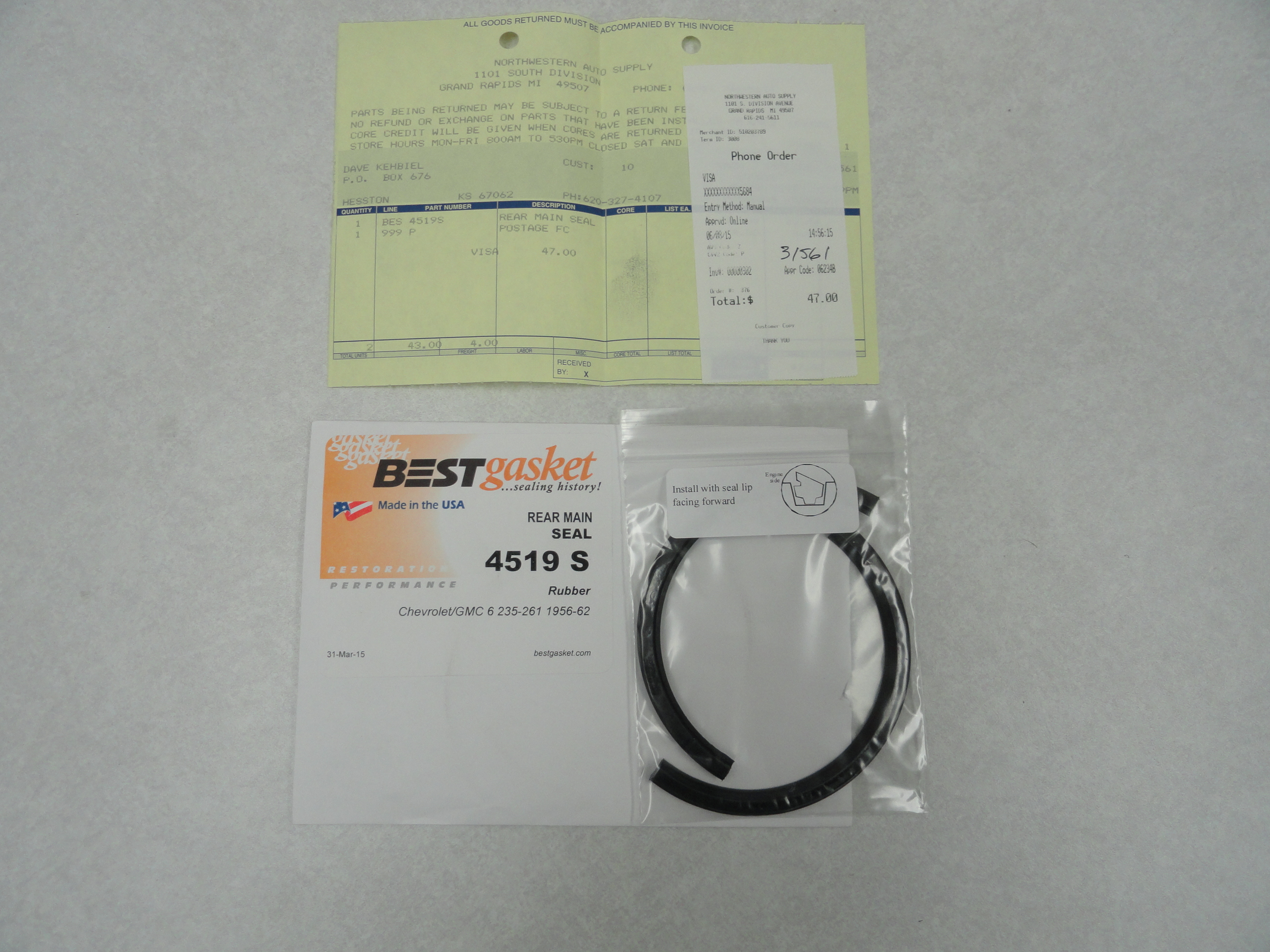 There are 4 crank caps. The rear one is the thickest one, then continuing up the block, the saddle one is next, then the thinnest one, then the front cap has
the flush surface. Be sure the bearings are properly marked with the correct clearance. For example, this build is .010 under, so each bearing should have .010
stamped on it somewhere. At least this is true if your machine shop made them all uniform. The writing on the intermediate caps are read left to right from
the back of the block. Once each crank bearing is properly installed in the block, and there is a liberal amount of assembly lube on the blocks bearing
surfaces, install the rear main seal. There are two types. One is a (usually orange) rubber one that slides through the track. The other, the one that came
with my kit was the rope type. It's impregnated cloth with some kind of Kevlar outer cover. I can see it working fine IF you can cut it per the Shop Manual.
I asked for help in determining which type of rear main seal is better and if there are ways to make sure the rear main doesn't leak prematurely. The consensus
was to use the rubber type seal that slides in the track. A "trick" on the neoprene seal: Install with a bit of offset in the block and matching offset in the
cap. That way the joint line between the halves won't match up with the seam line on the block and bearing cap. A drop of Permatex on the ends of the neoprene
seal works as well. -thanks Steve and Dave! Take your time on these steps and read the Shop Manual for that year engine to verify.
There are 4 crank caps. The rear one is the thickest one, then continuing up the block, the saddle one is next, then the thinnest one, then the front cap has
the flush surface. Be sure the bearings are properly marked with the correct clearance. For example, this build is .010 under, so each bearing should have .010
stamped on it somewhere. At least this is true if your machine shop made them all uniform. The writing on the intermediate caps are read left to right from
the back of the block. Once each crank bearing is properly installed in the block, and there is a liberal amount of assembly lube on the blocks bearing
surfaces, install the rear main seal. There are two types. One is a (usually orange) rubber one that slides through the track. The other, the one that came
with my kit was the rope type. It's impregnated cloth with some kind of Kevlar outer cover. I can see it working fine IF you can cut it per the Shop Manual.
I asked for help in determining which type of rear main seal is better and if there are ways to make sure the rear main doesn't leak prematurely. The consensus
was to use the rubber type seal that slides in the track. A "trick" on the neoprene seal: Install with a bit of offset in the block and matching offset in the
cap. That way the joint line between the halves won't match up with the seam line on the block and bearing cap. A drop of Permatex on the ends of the neoprene
seal works as well. -thanks Steve and Dave! Take your time on these steps and read the Shop Manual for that year engine to verify.
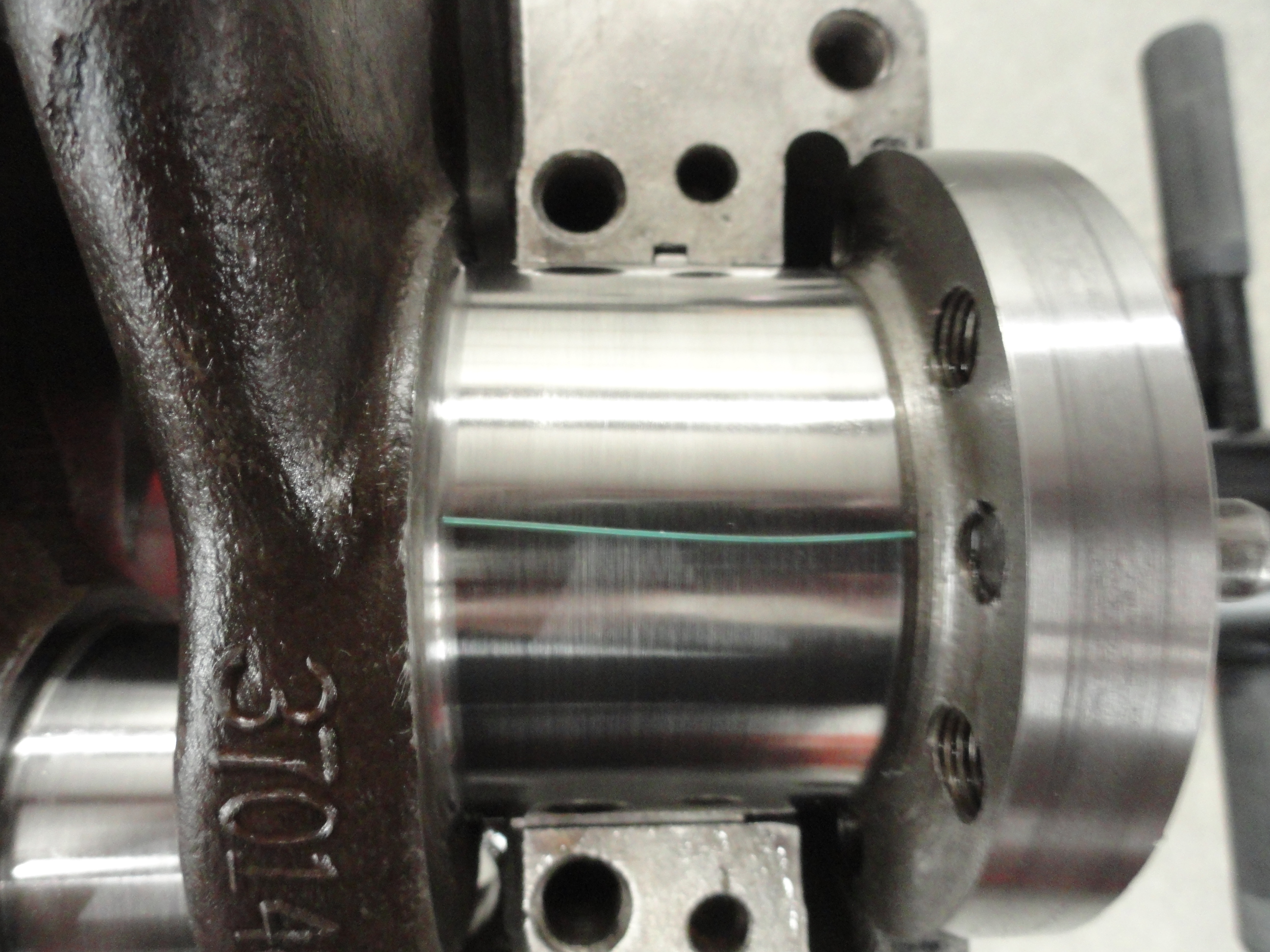
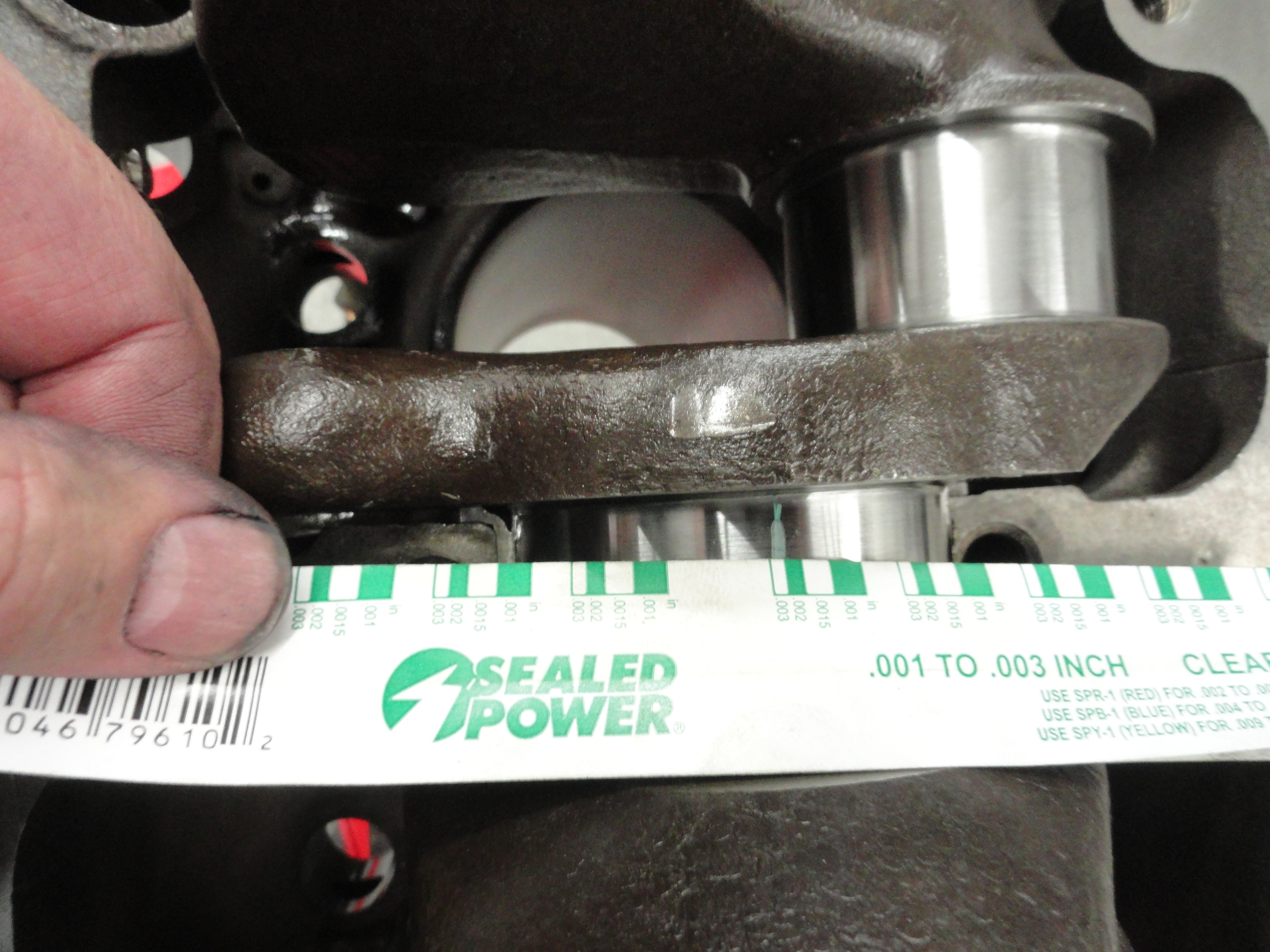
Now, making sure you have a liberal amount of assembly lube, carefully install the crankshaft. With the bearings installed, put the caps on and torque all
of them down to 110 foot pounds. Everything must be properly torqued for the Plastigage test. We only need to check the bearing tolerances in one place, the
top of each bearing journal. We can check the bearing tolerances with Plastigage. To do this, we will do one bearing at a time. Remove the rear main cap and cut off
enough Plastigage to go completely across the surface as shown. Clean off the assembly lube for this test (both surfaces). Evenly crank the bolts down to 110
foot pounds. Once tight, remove the bolts again and remove the cap. The smashed Plastigage will likely be on the journal. Use the measure on the side of the
Plastigage wrapper to tell what your bearing tolerances are. It has a repeating .001 to .003 inch gauge on it. If the number falls between .004 and .0005 the
bearing insert is satisfactory. If you have any doubt, get with your machine shop and resolve it. This is a pretty critical measurement. Do the same for all
bearing caps and journals. Remove the plastigage without scarring the journal (fingernail works good), put assembly lube back on and tighten to 110 ft pounds.
When you get to the front main cap, just hand tighten that one for the time being.
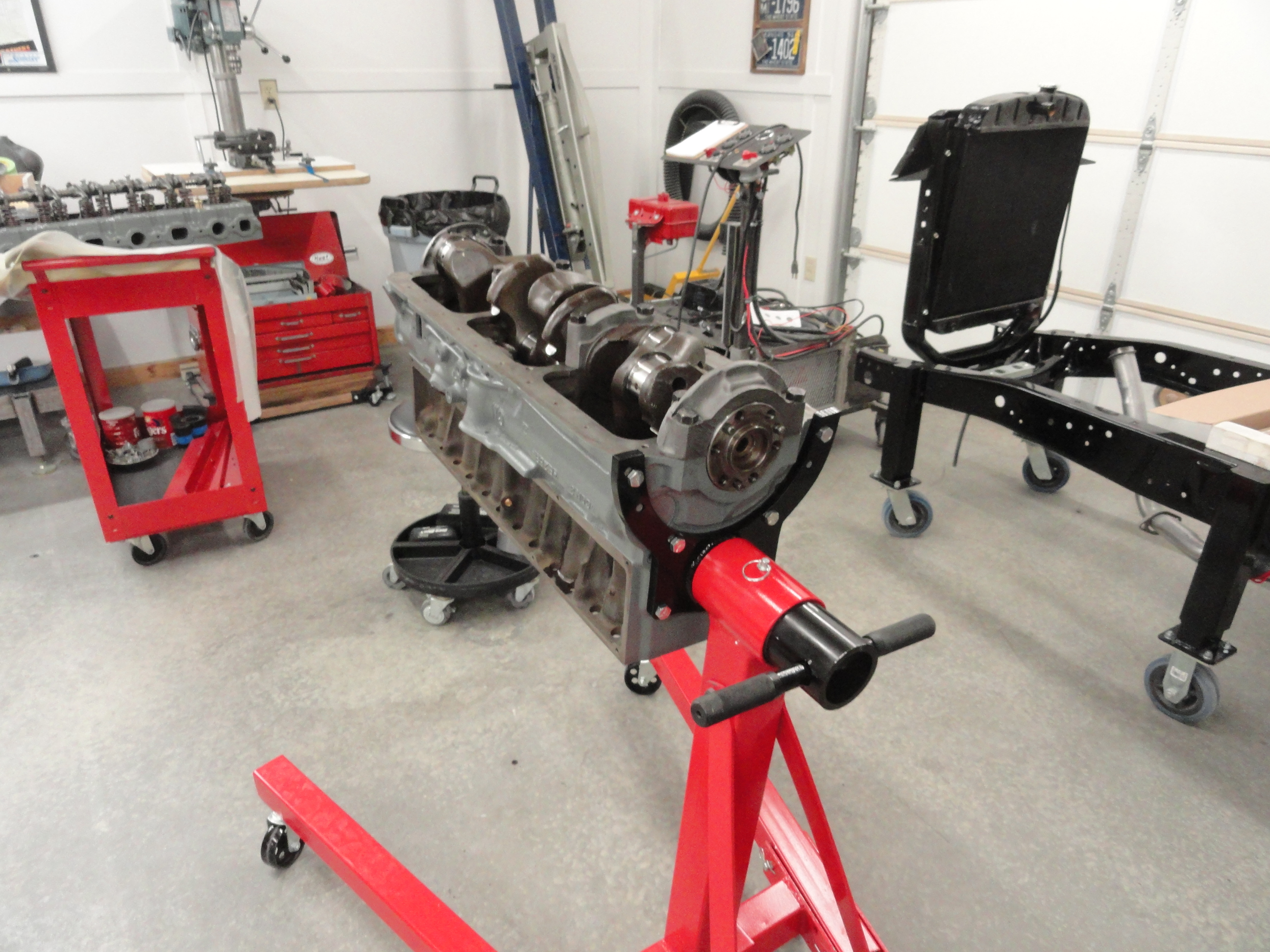 This is how the Project 1959 235 Crank came out:
Rear Main = .002
Rear Intermediate = .0025
Front Intermediate = .002
Front Main = .002
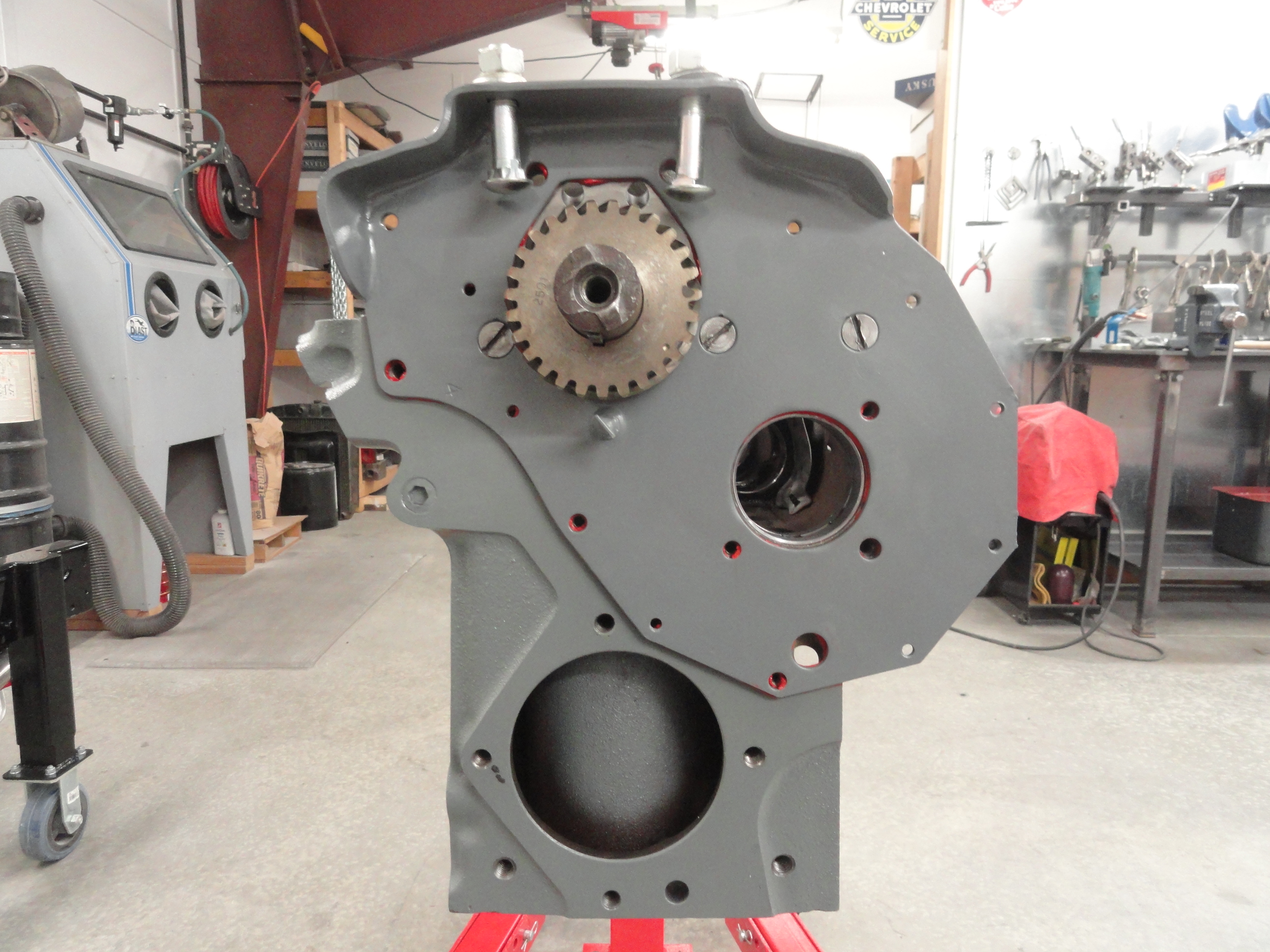
With your crankshaft installed, the next step is to install the timing plate. Use the gasket supplied with your kit. I use gasket sealer on all surfaces that require a gasket. Extra attention to detail during assembly pays high dividends in longevity and a quality build. Once the gasket is gooped up, use the three countersunk screws that attach it. Now is a VERY good time to put the two front engine mount bolts through the holes. You do not want to install your timing cover and then decide you really should have put the bolts in before. Read as, one of them especially does not go in the hole after the cover is installed! I wanted to make sure those three countersunk screws were torqued down tight. A very wide, thick screwdriver must be used for this. I used a crescent wrench on the shaft of my screwdriver and was able to get another 1/3 of a turn out of them without nastying up the slots. For engine parts I cannot get to easily, I do this as a routine.
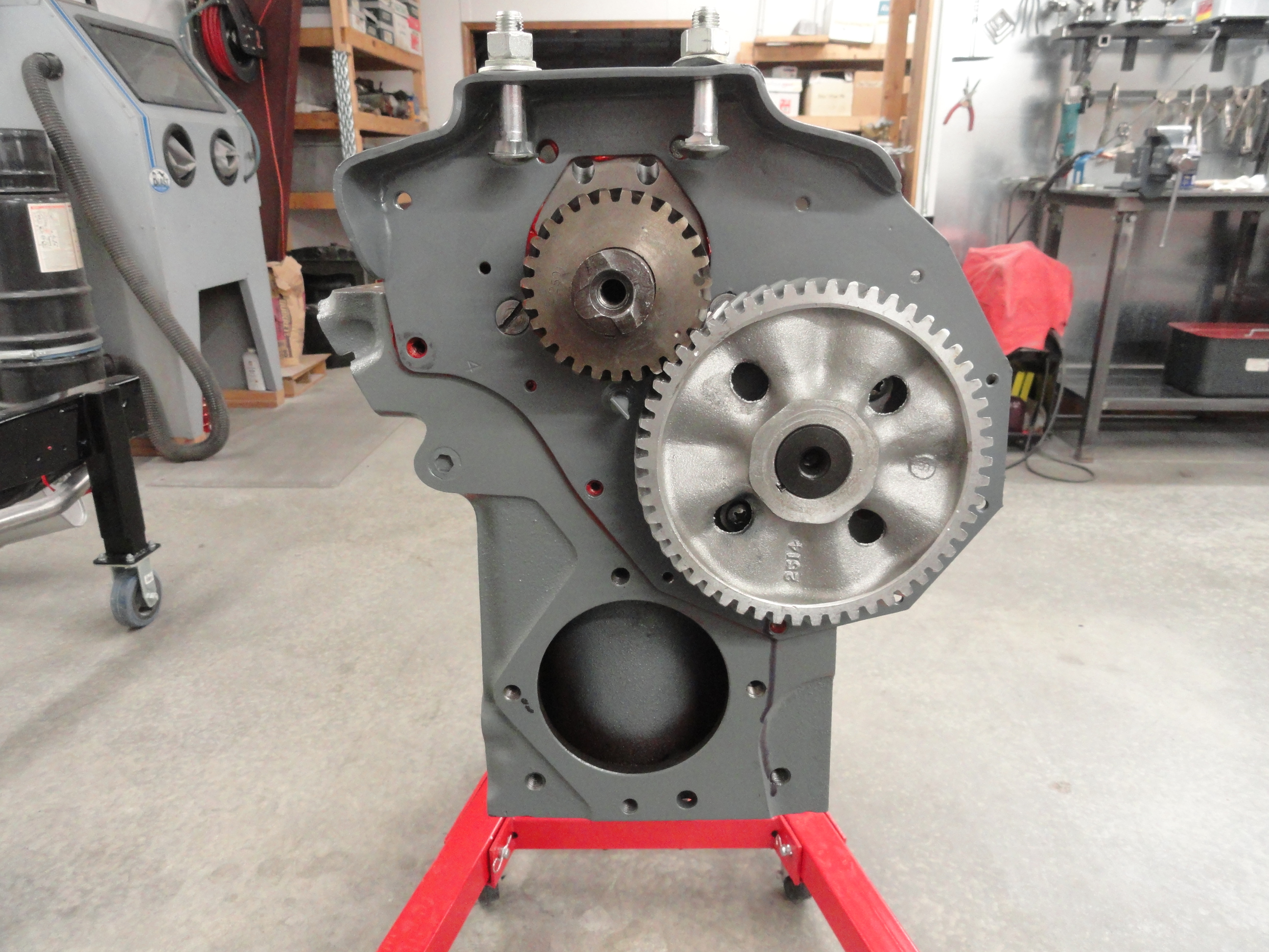
With the Timing Plate installed, it is now safe to put the Camshaft in. I had my machine shop install the cam gear and retainer. Presumably so it's done right, but let's check. With a feeler gauge, check between the back of the retainer and the front of the first bearing journal. With a feeler gauge, make sure you have less than .004. This one was .0015. Check it in several places around the shaft to see if you can detect any imbalance. It was the same all the way around. So I would say they did a great job! It is very important that the cam gear runs perfectly true. If it isn't installed correctly, it will make lots of noise.
Next, to install the Cam, we want to apply liberally Assembly Grease. Not Assembly Lube. We need something a little longer lasting on the cam lobes. Grease the lobes and all bearing surfaces well. The cam is the most finicky during the initial break-in process. Carefully install the Cam in the engine assembly. Use both hands and make sure not to nick any of the bearings. When you get to the point where you are meeting the crankshaft gear, mate them together with the timing marks exactly together, then push it in all the way. Use the two camshaft retainer screws that go through the holes in the gear to tighten down the cam. I like to get them good and tight! I have heard horror stories about them getting loose. Since I am older and do not have the torque I used to, and these are Phillips head screws, I use a vise grip on the shaft of my screwdriver to get more torque. I can turn it about 1/4" further that way. I also use medium strength Loctite on the threads. I can sleep at night knowing this camshaft isn't going anywhere! Now if you are not installing brand new gears and didn't have the experts machine everything, there are other measurements to consider to ensure you have everything correct. Consult the shop manual for backlash, runout, etc.

Once you are sure everything is properly torqued and ready, install the oil seal in the timing cover. Open end towards the inside of the cover. Do not gorilla this seal! You can easily ruin not only the seal, but the timing cover too. I use a 3/4 drive 1-5/8" socket. It covers the entire surface and then I tap on it as straight as possible until it begins to seat, then look carefully at where I am and tap it the rest of the way in accordingly. You can use a block of wood with the same result. Be gentle and it will go in pretty nicely.
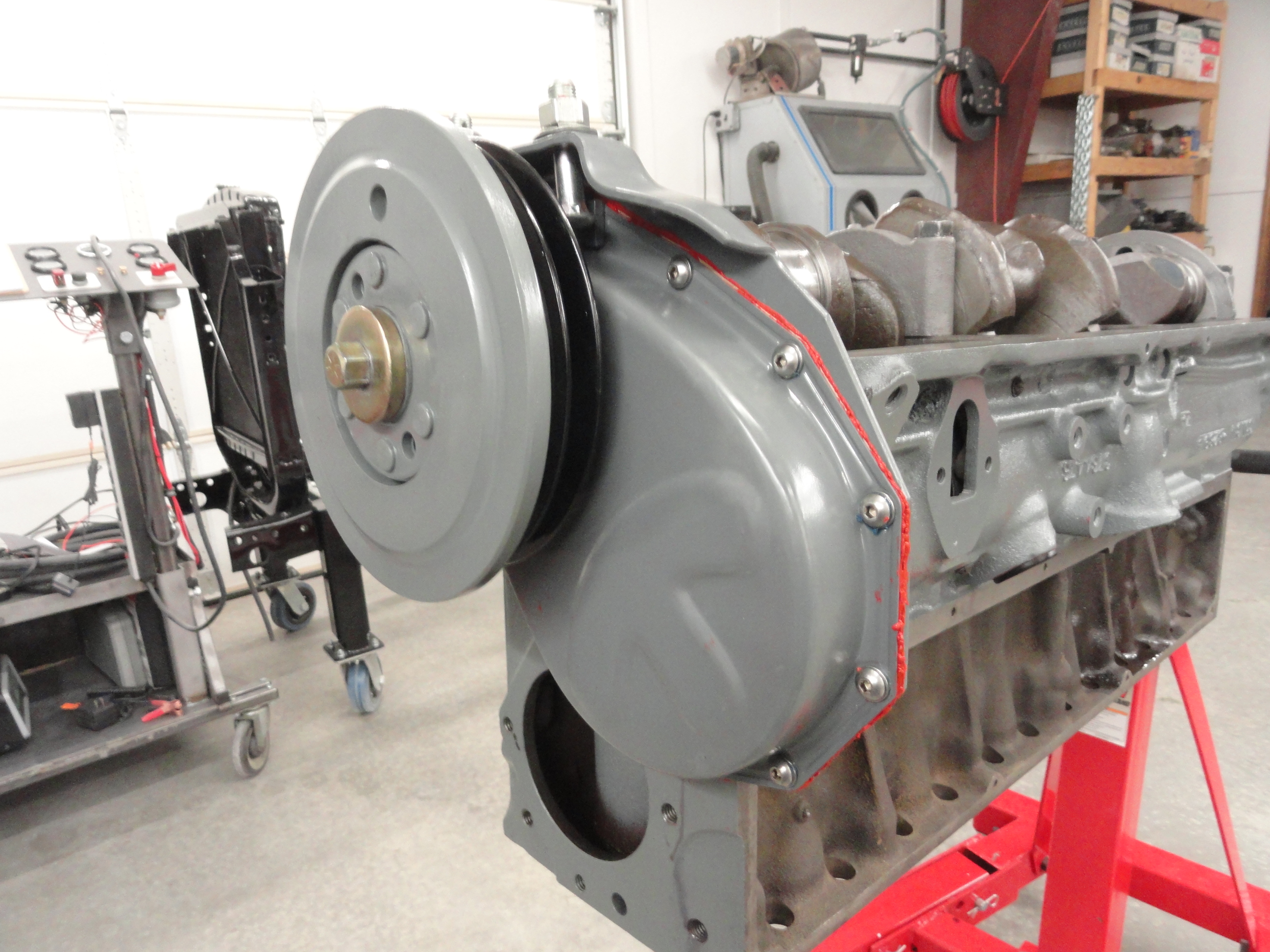
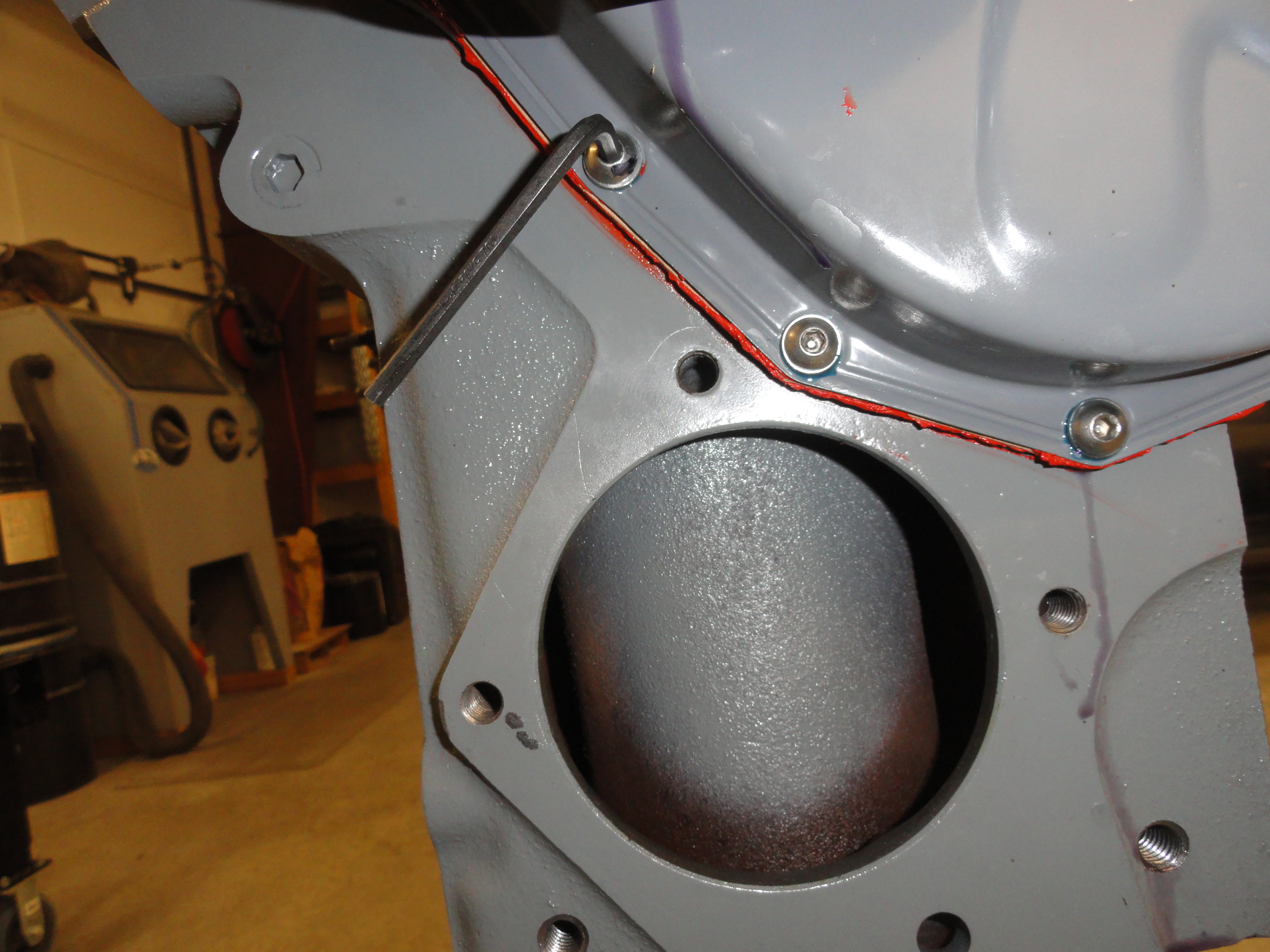
The Timing Cover goes on next. Installing the timing cover is pretty straightforward except for the two hex bolts that go through from the engine inside. Be sure your front Crankshaft Bearing cap is loose, then install the two hex head bolts but loosely. Install the rest of the screws for the timing cover with lockwashers but less than hand tight only. Reason being, I have no idea what a harmonic balancer centering gauge even looks like, but I DO have a Harmonic Balancer. With everything loose, install the Harmonic Balancer. Use a large ball peen hammer and a block of wood. Line up the keyway so it starts itself. It will go on until it stops. It isn't an exact science, but hammer until it no longer moves. With the balancer installed press-fit around the crankshaft, install the harmonic balancer retaining bolt (this was one of the improvements I had the machine shop do. I do not like 'fitted' balancers and feel much better with a 7/16-24 bolt holding it in.) Use an air impact wrench and torque it down good. See if the harmonic balancer moves in more. If not, you are probably good to go. Now tighten all the bolts for the timing cover. Do not forget the two hex head bolts inside the front bearing cap. Use the retainer plate to secure those two. Once your hex bolts are tight, don't forget to torque down your front crankshaft bearing cap to 110 foot pounds like all the rest. DO NOT FORGET TO TORQUE DOWN THE FRONT BEARING CAP! The torque spec for the small screws is 6-7-1/2 foot pounds. If you are uncertain where that extra long screw goes, see the picture with the Allen wrench sticking out. That's where it goes!

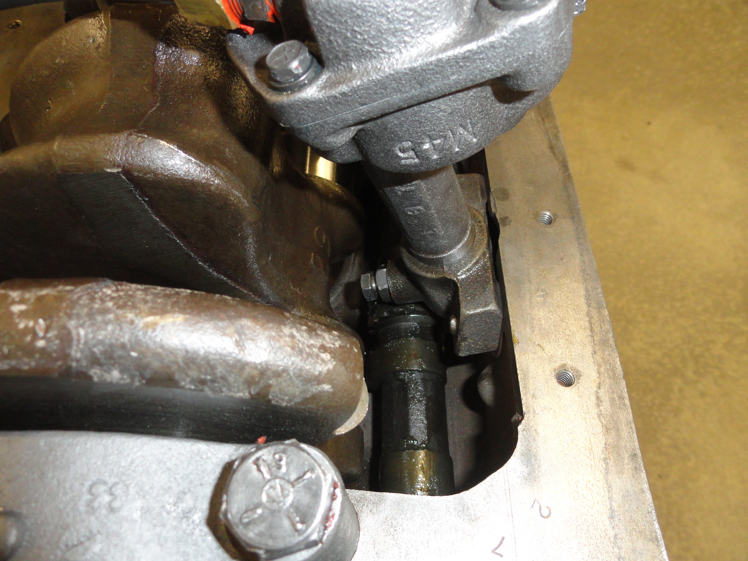
The Oil Pump Assembly is next. To reconnect everything properly, we need to do this in the proper sequence, otherwise the fittings will be impossible to line up correctly. Screw on the pickup screen assembly so that it is tight, but sticking up as shown. I use high temp copper gasket sealer on the threads of this entire assembly. I just feel better knowing it won't get loose. Set the oil pump in place, and hand tighten the oil pump retaining screw. I used medium Loctite on that. Now the problem is the hard line to the other side of the block does not flex enough to just put it on last. Install both adapters, one in the oil pump, the other in the block across from it. Tighten down good. Remove the top of the oil pump with 4 screws. Now you can get that hard line in there. Tighten the fittings first, then put the screws back in the oil pump using medium Loctite. Take a screwdriver and rotate the oil pump to make sure it rotates freely. If it does, tighten the retaining screw one last time and lock it down with the lock-down nut.
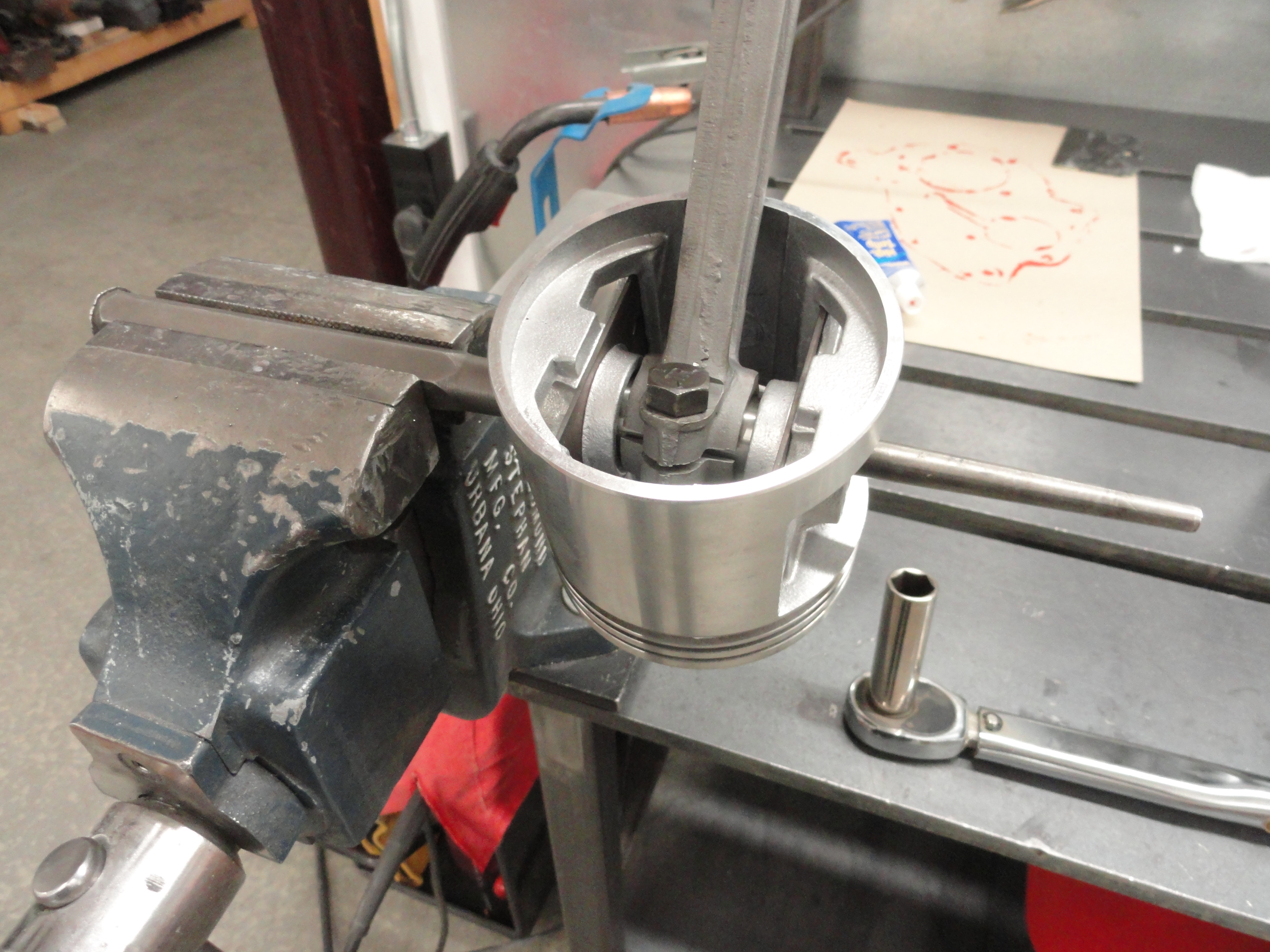
The Pistons are next. To install the pistons on the piston rods, orient the rod so the clamp part of the rod is on the cam side of the block. The
cylinder number is also facing the cam side. The cylinder number should be stamped near the piston rod bearings. The piston itself has an arrow on its top
edge. Face them all toward the front of the engine. Once oriented properly, remove the piston pin, slide the piston over the rod and install the pin. Do
your best to center the rod inside the piston, then tighten it down.
NOTE: The Shop Manual is specific about NOT using a bench vise to clamp the piston rods in as you tighten the clamp. They do not want you twisting the
rods. To comply with this and do it safely, use a long punch, or a length of rod. Place this rod sticking outwards in your vise. Slide the piston on the
rod through the piston pin hole. Tighten the clamp down to 35 foot pounds.
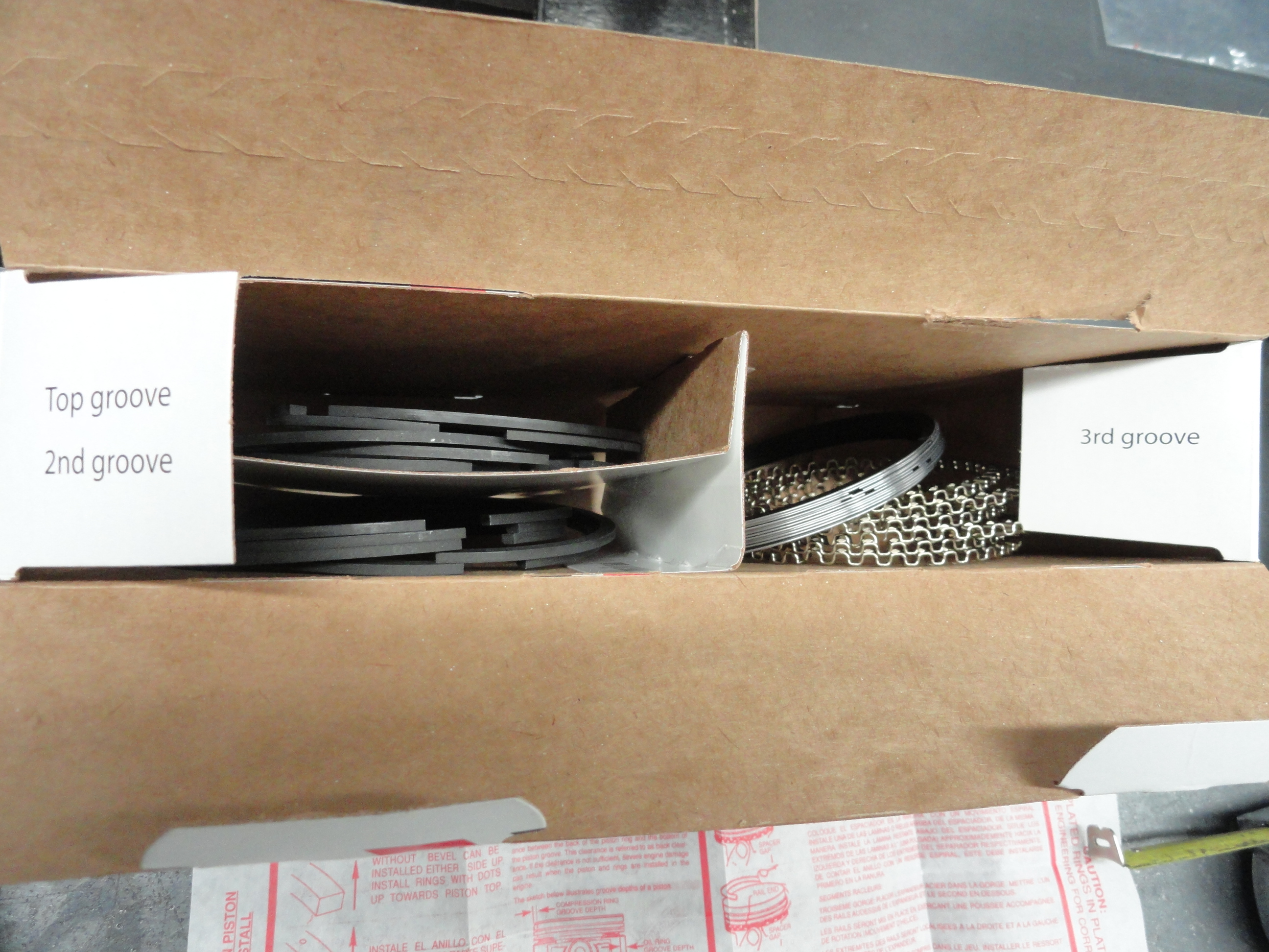
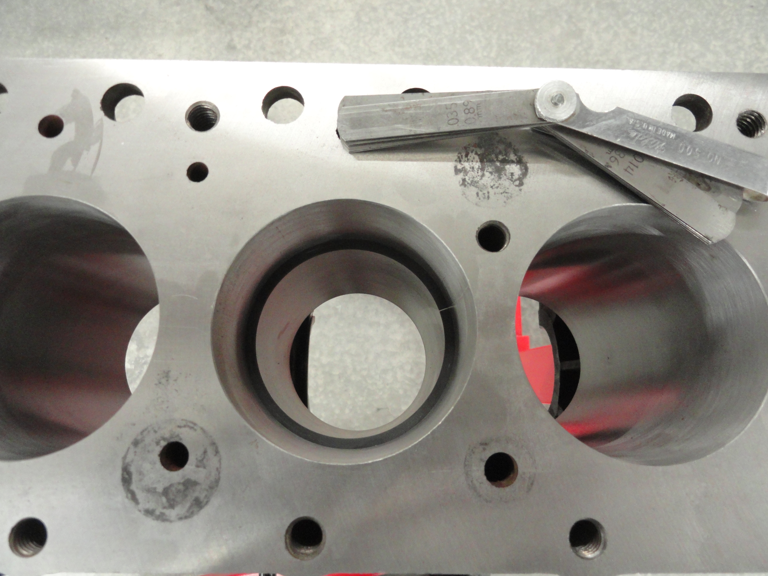
Installing the Piston Rings correctly is very important. The .080 overbore of this particular engine means the rings have to be matched to the
pistons and cylinders. The machine shop took care of ordering the set. To check to make sure you have the right ones, place each ring in the cylinder bore
about two inches down from the top. Push it that far down with the piston so the ring is flat. We go down the 2 inches because that is far enough to
stabilize the piston in the cylinder to give us a nice flat measuring surface. With a standard gap gauge in the proper range, check the gap thickness.
Compression Ring Gap tolerance for this engine is .007 to .017
Oil Ring Tolerance for this engine is .015 to .055
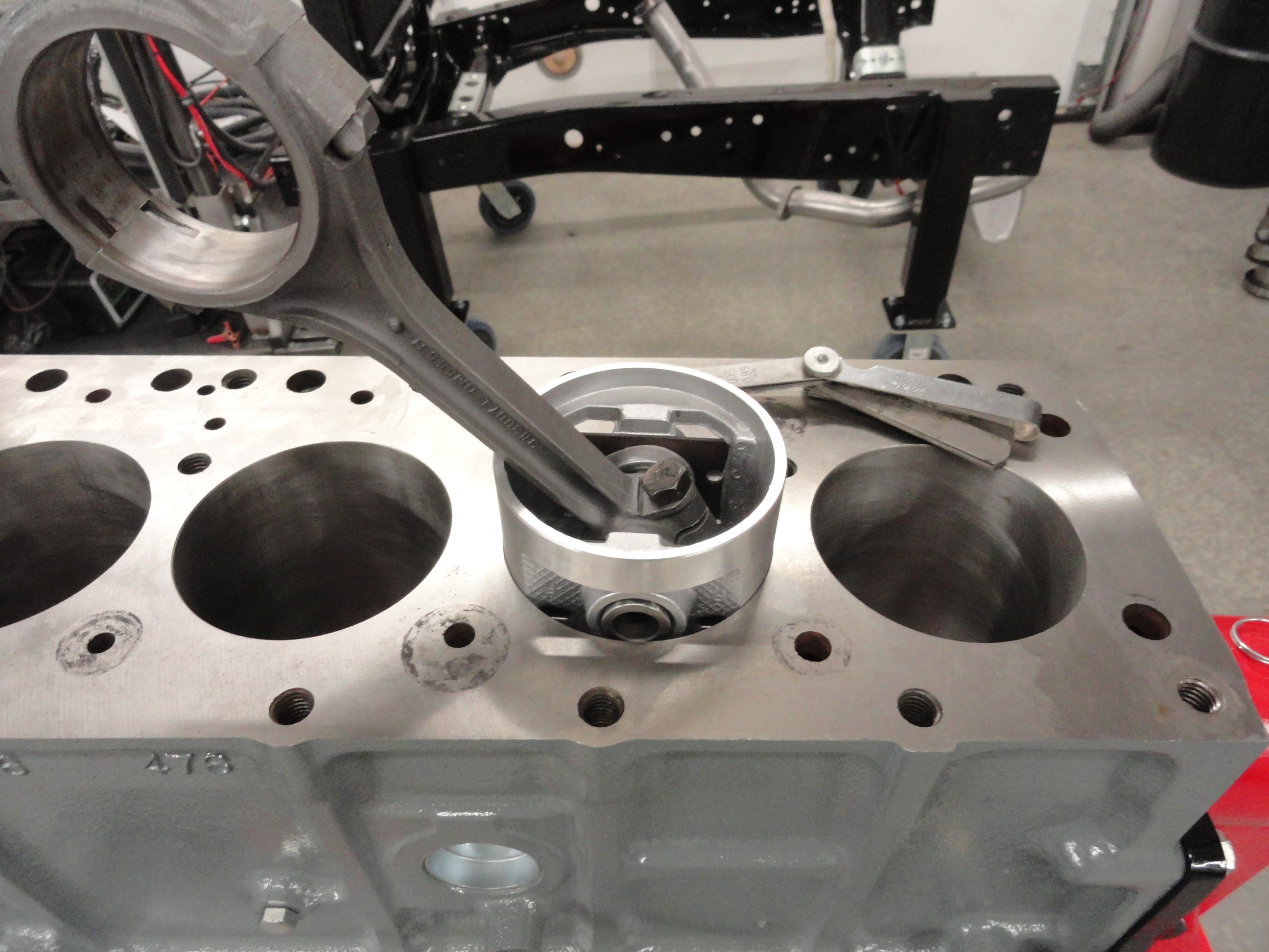 Cylinder #1: Compression Ring #1 (top): .015
Compression Ring #2 (center):.014
Oil Ring #1: .024 (top)
Oil Ring #2: .022 (bottom)
Cylinder #2: Compression Ring #1 (top): .012
Compression Ring #1 (center): .015
Oil Ring #1: .025 (top)
Oil Ring #2: .024 (bottom)
Cylinder #3: Compression Ring #1 (top): .015
Compression Ring #1 (center): .015
Oil Ring #1: .024 (top)
Oil Ring #2: .022 (bottom)
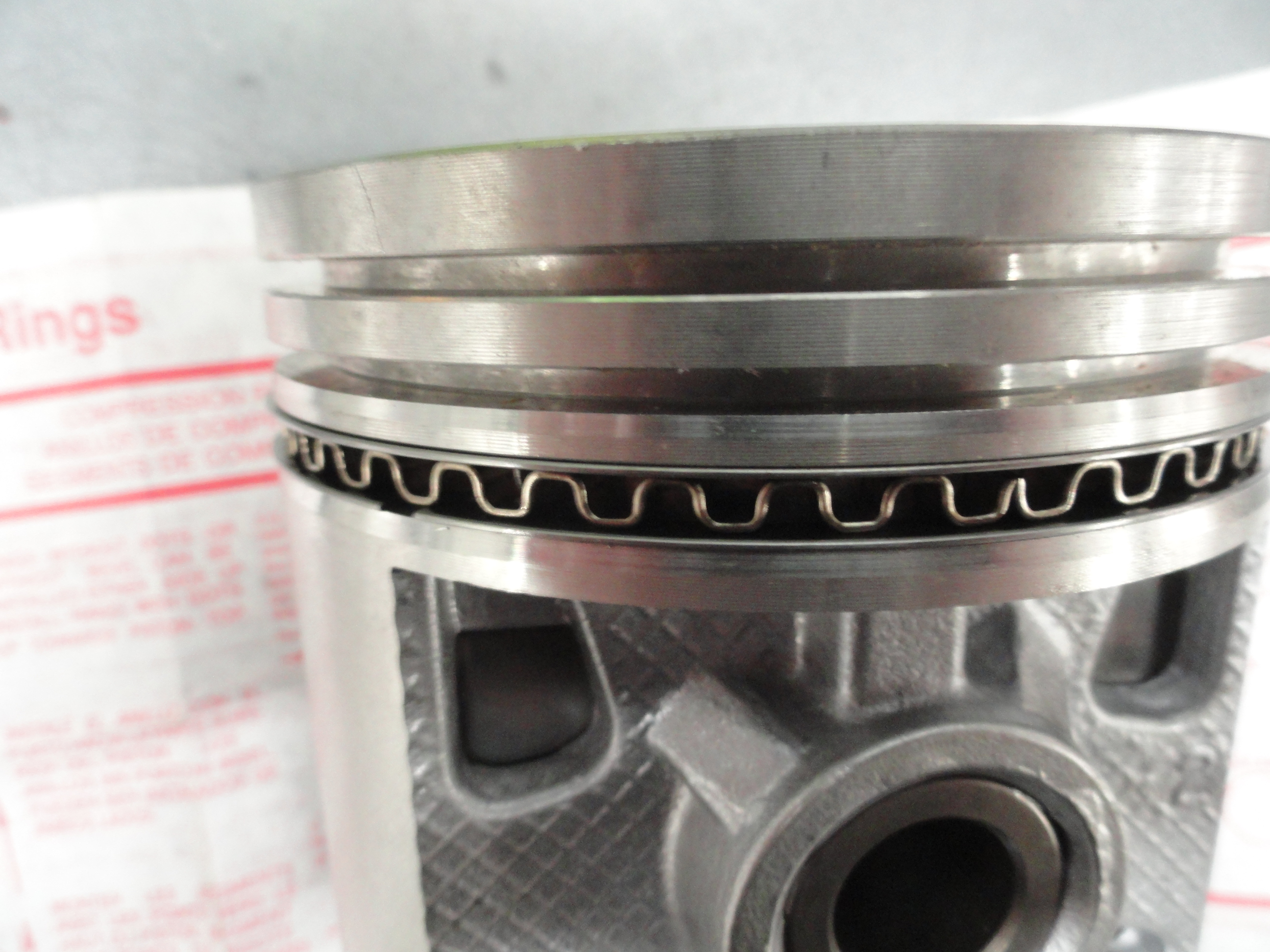 Cylinder #4: Compression Ring #1 (top): .013
Compression Ring #1 (center): .014
Oil Ring #1: .024 (top)
Oil Ring #2: .025 (bottom)
Cylinder #5: Compression Ring #1 (top): .014
Compression Ring #1 (center): .015
Oil Ring #1: .025 (top)
Oil Ring #2: .024 (bottom)
Cylinder #6: Compression Ring #1 (top): .015
Compression Ring #1 (center): .014
Oil Ring #1: .025 (top)
Oil Ring #2: .024 (bottom)
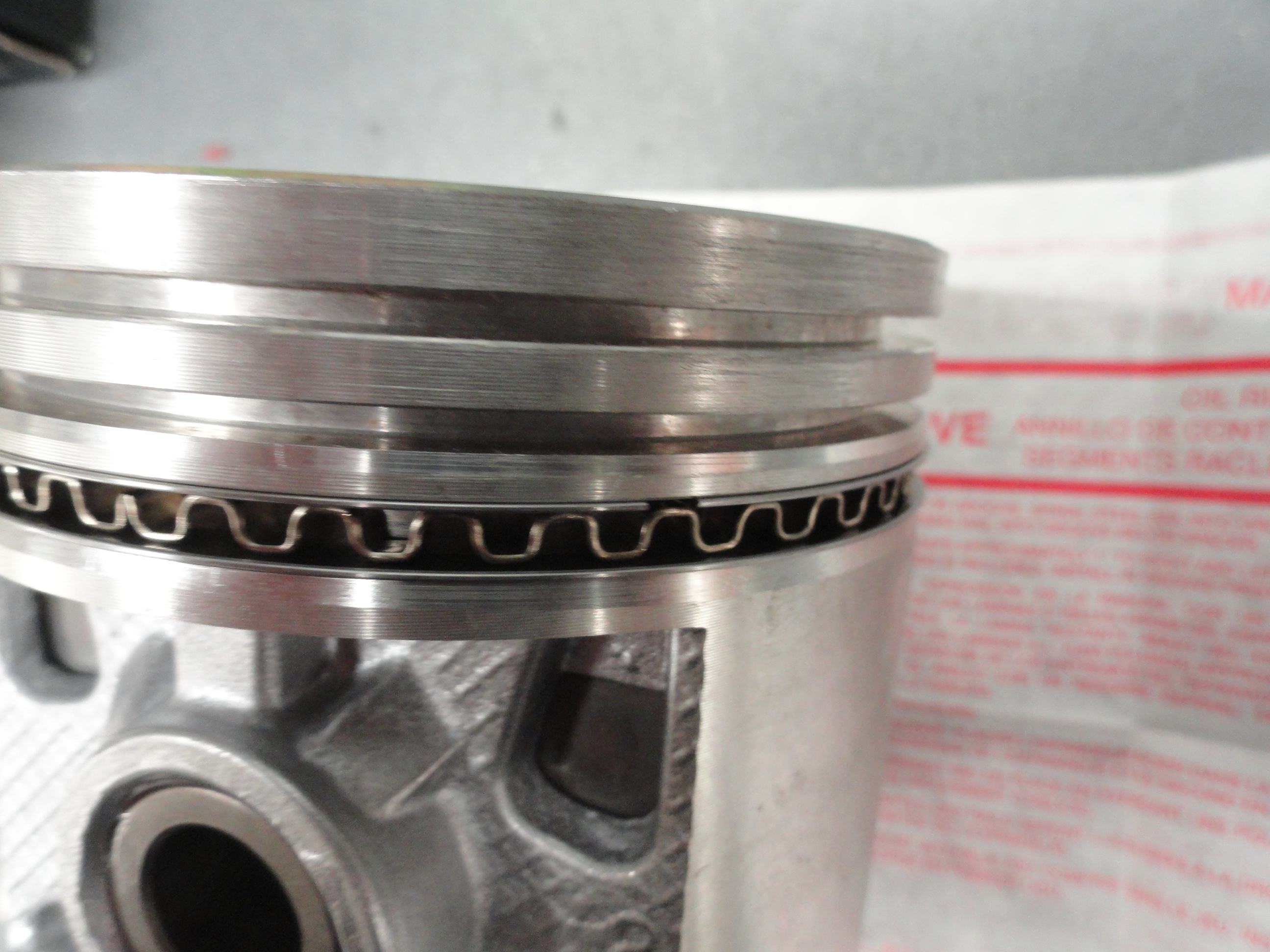 Installing the rings is controversial according to what YouTube video you go and watch. The Shop Manual suggests just rolling the rings on without tools.
Other places suggest that can cause deformities and to use a piston ring pliers to put equal pressure on the entire circumference equally. We are going
to follow the shop manual and carefully use the roll method on the oil rings. It's basically just starting one end in the groove and carefully rolling the
ring into place. Use your finger on the final end to prevent the sharp edge of the ring from scarring the piston. On the compression rings, I use a Piston
Ring Pliers. It's so much easier and you do not run the risk of scarring the piston. If you are confused as to what compression ring goes where, the very
top piston ring has no chamfer or markings on it, the second compression ring has a chamfer on it and has a dot on the top of it.. yes, the dot goes up (chamfer
down). When installing the oil rings, the center expander goes in first.
Installing the rings is controversial according to what YouTube video you go and watch. The Shop Manual suggests just rolling the rings on without tools.
Other places suggest that can cause deformities and to use a piston ring pliers to put equal pressure on the entire circumference equally. We are going
to follow the shop manual and carefully use the roll method on the oil rings. It's basically just starting one end in the groove and carefully rolling the
ring into place. Use your finger on the final end to prevent the sharp edge of the ring from scarring the piston. On the compression rings, I use a Piston
Ring Pliers. It's so much easier and you do not run the risk of scarring the piston. If you are confused as to what compression ring goes where, the very
top piston ring has no chamfer or markings on it, the second compression ring has a chamfer on it and has a dot on the top of it.. yes, the dot goes up (chamfer
down). When installing the oil rings, the center expander goes in first.
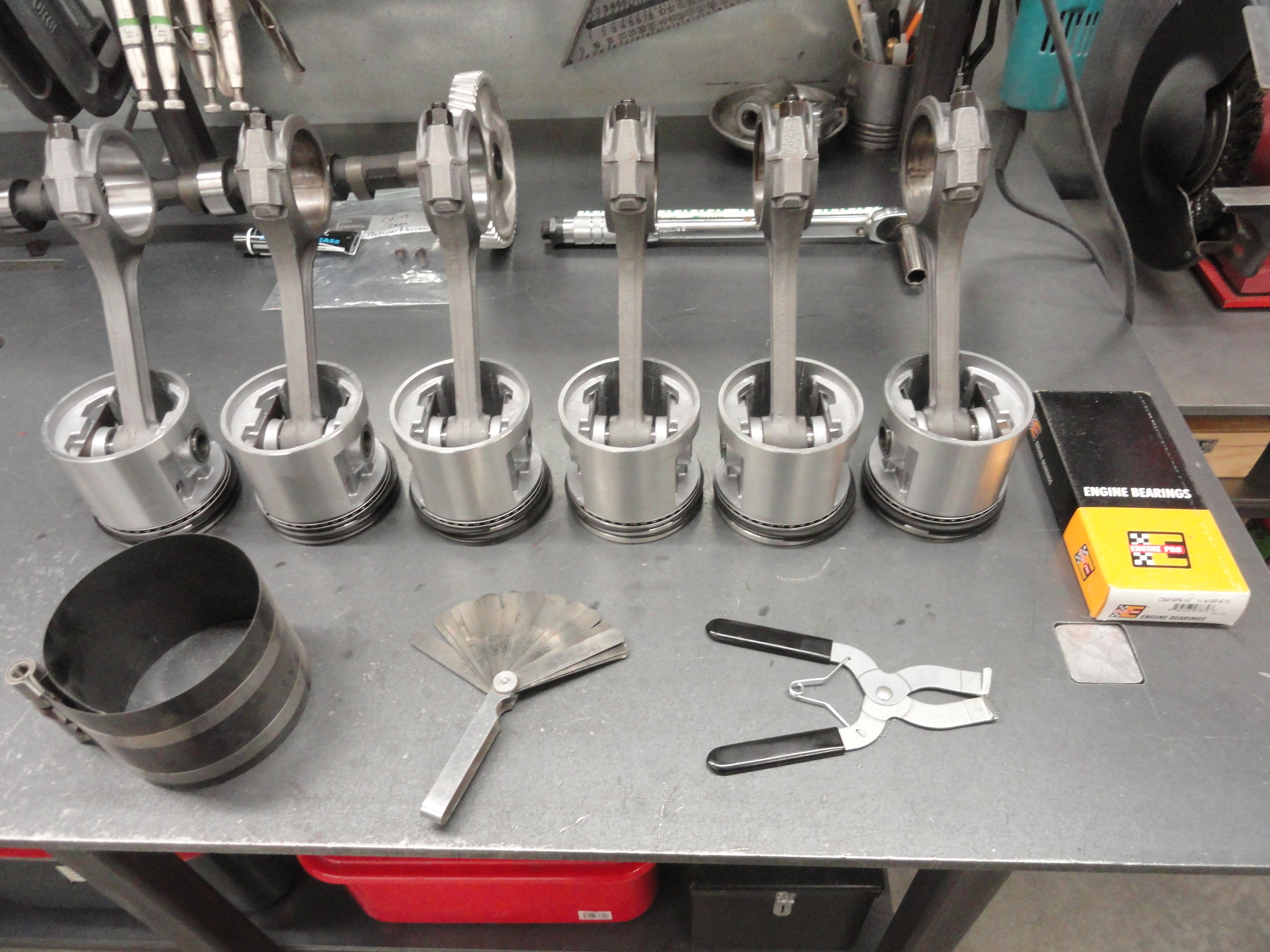 Positioning the rings or "clocking" the rings is a crucial step. If all of the gaps were lined up, it would give oil a perfect avenue to travel where it's
not wanted and due to the gap, compression would suffer. You want to make sure they are 120 degrees from each other. (3 sets of rings divided by 360
degrees). This is only slightly complicated by the oil ring set because the shop manual specifies that you place the top oil ring no less than 1" to the
right of the center (spacer) and the bottom oil ring no less than 1" to the left. The idea is to be VERY certain your gaps do not even come close to lining
up. I use the sidewall of the piston as my gauge for the oil rings. One on the left, one on the right, spacer centered on the piston pin. Even though this
is a time consuming and painstaking process, it's worth taking the time to check the gaps and get the clocking right. Just before we install the Pistons
into the cylinder, we will check the clocking again.
Positioning the rings or "clocking" the rings is a crucial step. If all of the gaps were lined up, it would give oil a perfect avenue to travel where it's
not wanted and due to the gap, compression would suffer. You want to make sure they are 120 degrees from each other. (3 sets of rings divided by 360
degrees). This is only slightly complicated by the oil ring set because the shop manual specifies that you place the top oil ring no less than 1" to the
right of the center (spacer) and the bottom oil ring no less than 1" to the left. The idea is to be VERY certain your gaps do not even come close to lining
up. I use the sidewall of the piston as my gauge for the oil rings. One on the left, one on the right, spacer centered on the piston pin. Even though this
is a time consuming and painstaking process, it's worth taking the time to check the gaps and get the clocking right. Just before we install the Pistons
into the cylinder, we will check the clocking again.
Time to Install the Pistons! I like to do this slowly, flipping the engine over at each set so I do not inadvertently mess something up. In other words, don't get in a hurry here. Rotate the engine stand so you have the top of the engine UP. Its very important we get these pistons in the correct way. The piston rod bearing housings have a number on them which is the cylinder number. That number goes on the cam side. Using a Piston Ring Compressor, we will oil the inside of the compressor tool, the cylinder walls and the pistons themselves. Experts tell me to not use assembly lube here. Use a good SAE30 non-detergent motor oil. So slather that stuff on everything involved! The cylinders are numbered 1 through 6 with number One being in the front. Starting with #1, check the clocking on the rings to make sure each ring opening is way far away from another one.
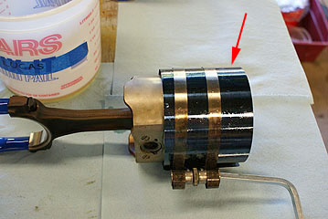
Install the piston ring compressor so that about half of the piston is in the compressor, the other half down in the cylinder. Once you have the ring compressor on securely, no worries. Do not get your parts mixed up, or get the orientation of the pistons wrong. The rings are very sloppy in their correct positions so you will have a little wresting to do with the clocking issue. Its VERY important your rings do not move. This is why they call us grease monkeys. We have to have three hands! The most efficient way to do this is to do the two that are in the same place at the same time. So we will install #1 piston and #6 piston since the crankshaft is in the same place for both. We will then rotate the crank so it is on its bottom-most point for #2 and #5. Lastly we will so the same for #3 and #4. Make sure you don't mar the bearing surfaces with the rod bolts. If you don't trust yourself, tape the ends of the bolts with masking tape. I don't do the masking tape thing, but I do turn the crank so that the crank bearing surface is the furthest away from the top of the cylinder and in the center of the piston hole. This way the rod just drops right down in the perfect place. Of course guide it down with your fingers in the way to prevent scarring. Install the piston rod bearings on the rod side and use lots of assembly lube. All of the rod bearings are exactly the same. Just be sure to put a bearing on each one!
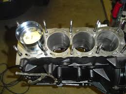
NOTE: Sorry for using whatever pics I could find off the Internet that matched the process, but when you are up to your elbows in SAE30, Assembly
Lube, and Assembly Grease, you don't pick up your camera!
Take #1 piston, install it in the cylinder with the rods piston clamp towards the cam. This also puts the number 1 stamped on the side of the
rod near the bottom on the cam side. Hold the piston from underneath so that the rod doesn't scar the cylinder walls or the crank bearing surfaces. I use
a shop rag stuffed in such a way to keep it where I want it. Maybe a few shop rags. Whatever works to protect the surfaces and have about half of your
piston sticking out the top for now. Oil the inside of your ring compressor. Once again check the clocking, then install the compressor and ratchet it
down tightly. Check underneath and make sure it looks like the bearing caps screws will go smoothly down and the bearing stays put. Then, take the wooden
end of your hammer and tap, tap, tap the piston down into the cylinder. If you made that compressor tight, it wont even know! Very smooth operation.
Keep tapping until the bearing is tight on the crank.
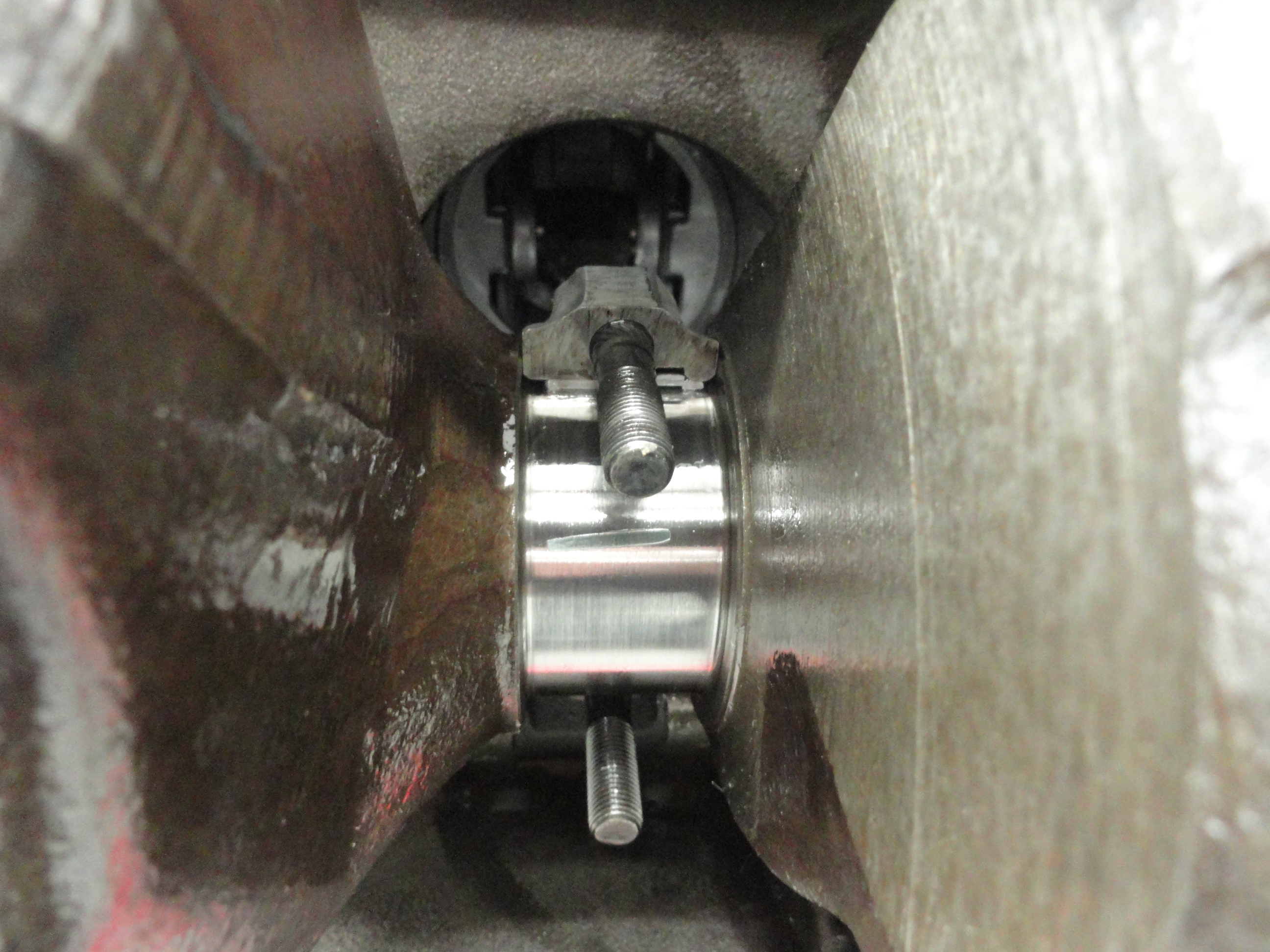
To check bearing clearances, we need to Plastigage the rod bearings in much the same way we did the crankshafts main bearings. Cut off a small piece of Plastigage and put across a CLEAN bearing surface (wipe off any assembly lube), then place the bearing cap with the bearing in the rod end, bolt it down and torque to 45 foot pounds. Remove the cap and read the plastigage. Since my machine shop did such a thorough job making sure to resurface the rods and caps, ALL SIX of the Piston Rod Bearings are .002. The spec is .001 to .003 for new bearings! Remove the plastigage, put assembly lube on the bearings and re-tighten the caps to 45 foot pounds. There is lots to think about and lots to do, to do this right. Take your time. You will sleep better knowing you did it right. With the proper ring clocking, proper ring gaps, proper bearing clearances, you just can't go wrong! Go back and make sure all rod caps are at 45 foot pounds, the oil pump connections are tight, everything you cannot get to after the oil pan is installed is completely ready for prime time.
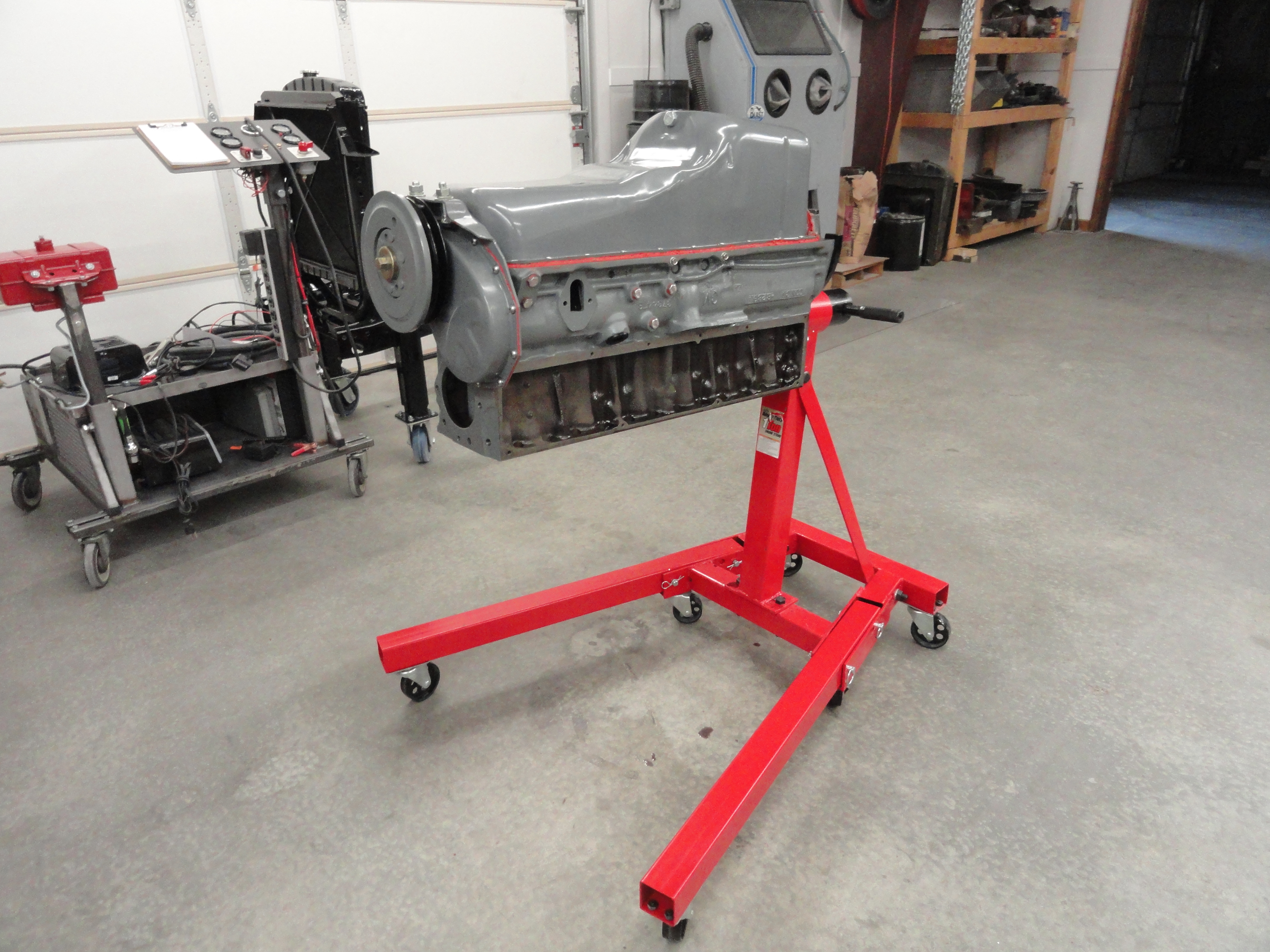

Once you are sure everything is good to go, put the rubber end pieces over the end caps using high temp copper gasket sealer on all surfaces. Lay out the correct gasket pieces left and right and make sure you are using the right ones. Gasket sealer on both sides once again but this time, concentrate on where the rubber meets the cork and put plenty of sealer there. Once you have everything all good and sealed, bolt the oil pan down starting with the 4 bolts in the corners, then start putting the screws in one by one. Tighten from the center out. Wipe of any excess sealer that is bothering you, and you have just successfully finished the bottom end of your engine!
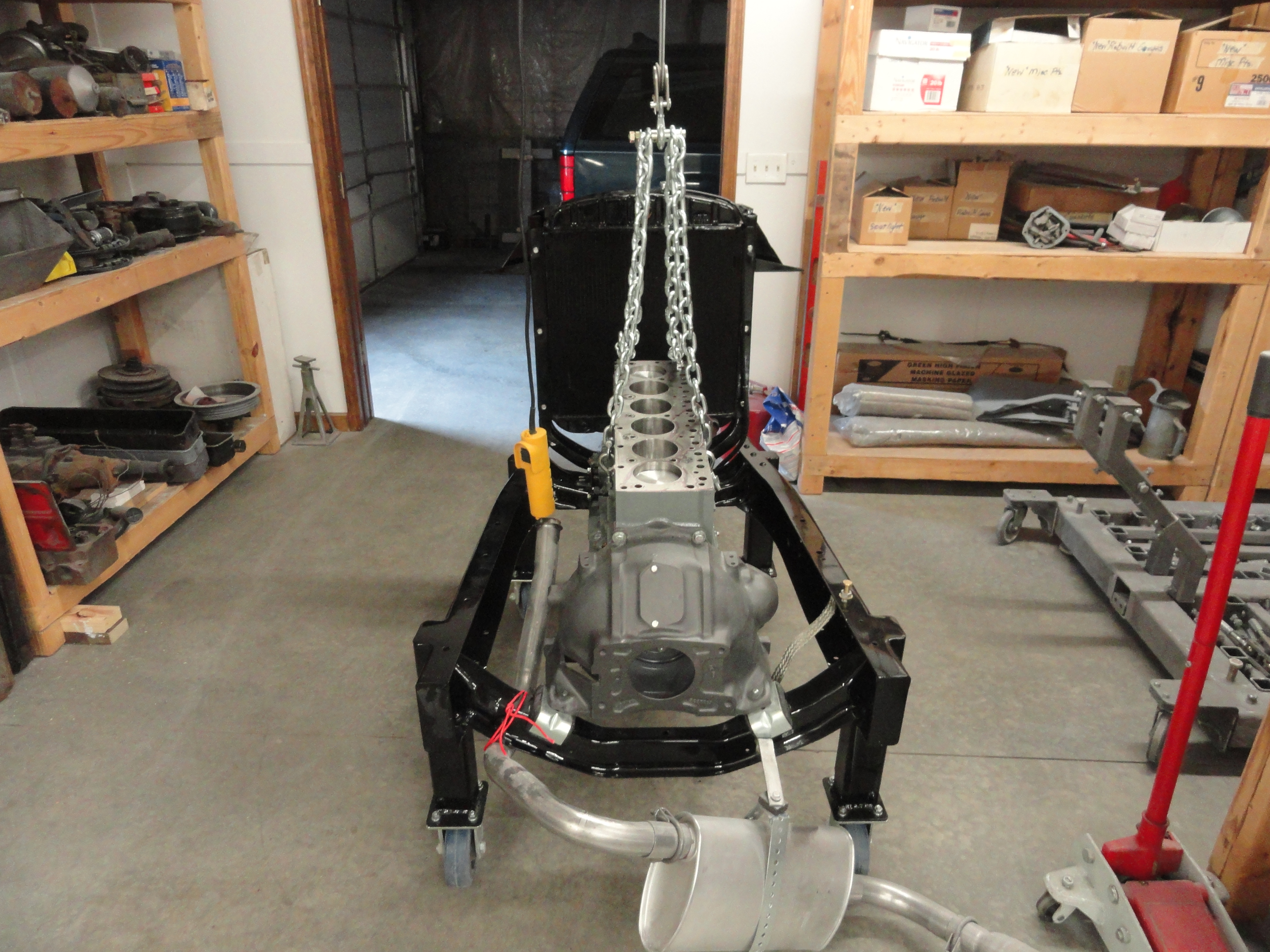
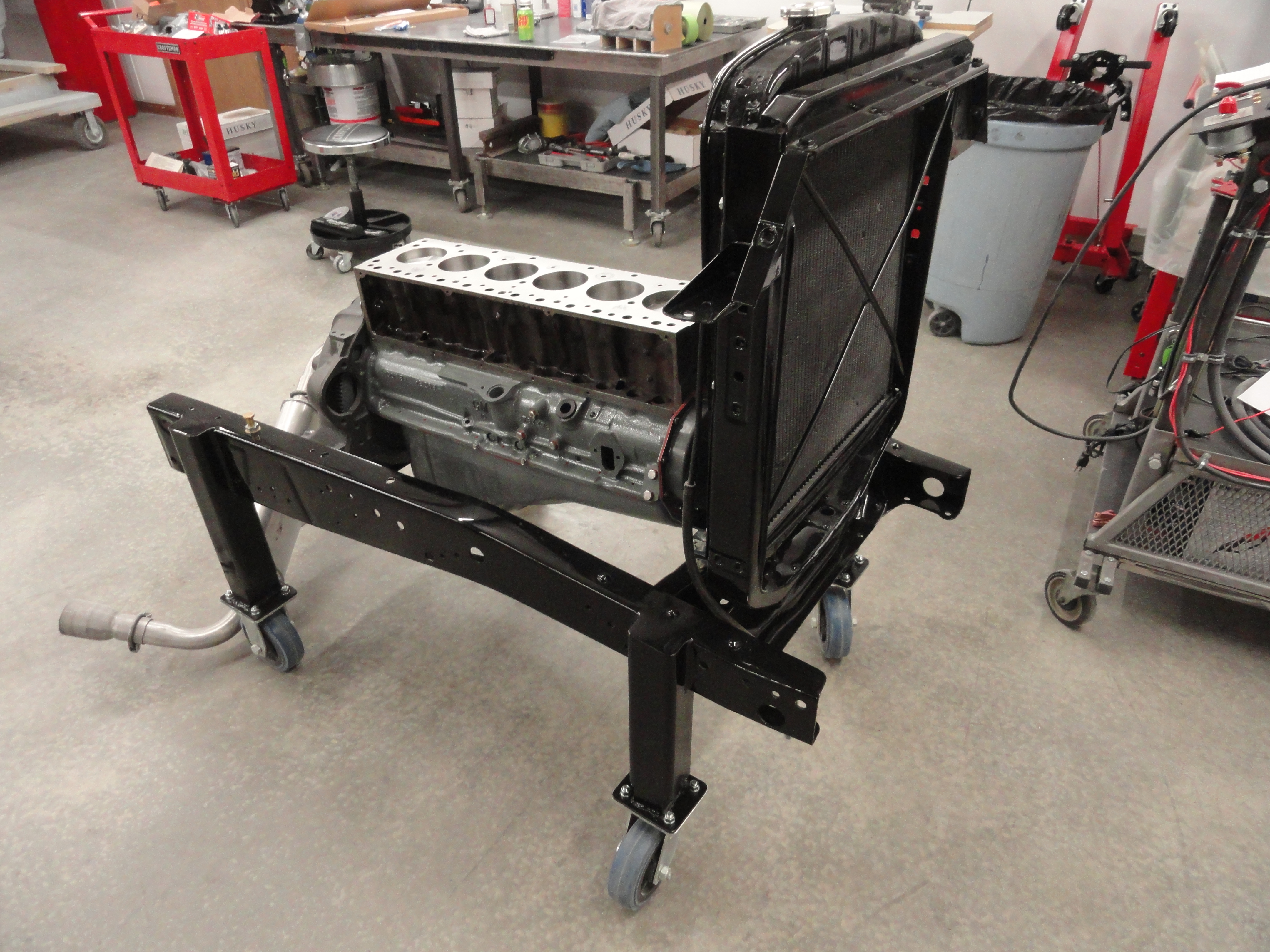
This is where I sort of differ from how you may do it. I take the engine off the engine stand and put it on a test stand for installing the head and finishing. This is merely the front end of a 1954 truck that was badly burned out. I put wheels on it, painted it, and now it acts exactly as if it were going in an actual frame-up restoration. I use a Harbor Freight 880 pound 120volt Electric Winch that I installed on a support beam to move the engine around. Makes things a whole lot easier. After I install the Head, I will take off the radiator so I can get to the front of the engine better.

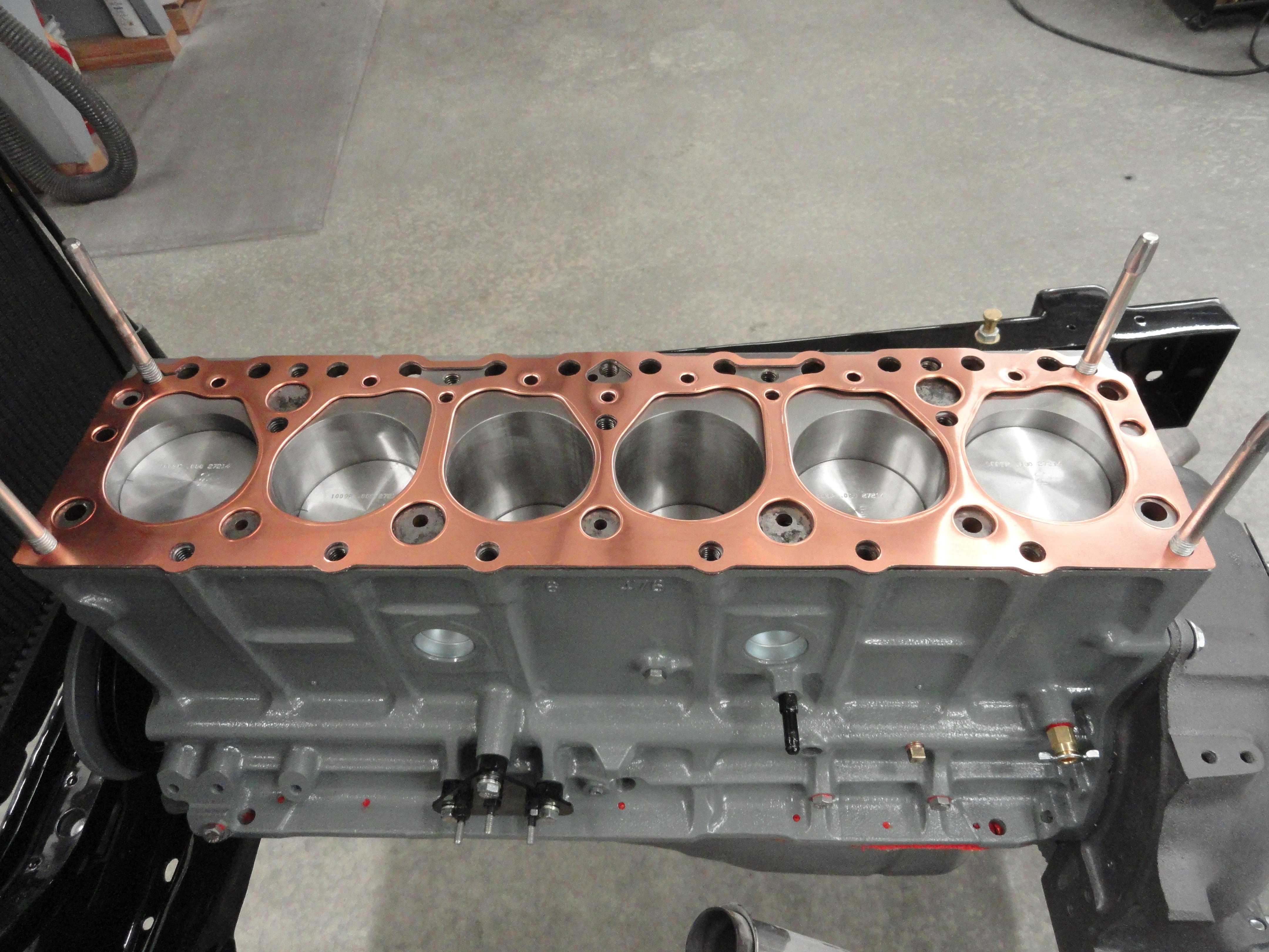
The next thing on the TO-DO list is to install the Head. You can run into all sorts of problems installing a Head if you don't take a little time first and make at least two guide pins. This ensures the gasket stays perfectly centered and in its place when you set the Head down on it. I really believe in using 4 guide bolts. I made them from another old set of Head bolts. Do NOT cut the heads off of them! One corner in particular will be too short for you to get in there to pull it out. Grind the heads down leaving that extra meat on the bone. These guide pins are essential and you will be much happier with the result. Get your Head Gasket out of your kit and set it in place so that you understand the orientation of it clearly. This particular Fel-Pro Copper Gasket has a THIS SIDE DOWN stamped in it. What I like to do is place it, then look to see if the gasket is covering any holes. There shouldn't be an instance like that, however, I have heard differently. Know what it is that you are covering! Research and ask the Machine Shop to give clarification. In my case, there were NO holes covered by the gasket. I like it that way!

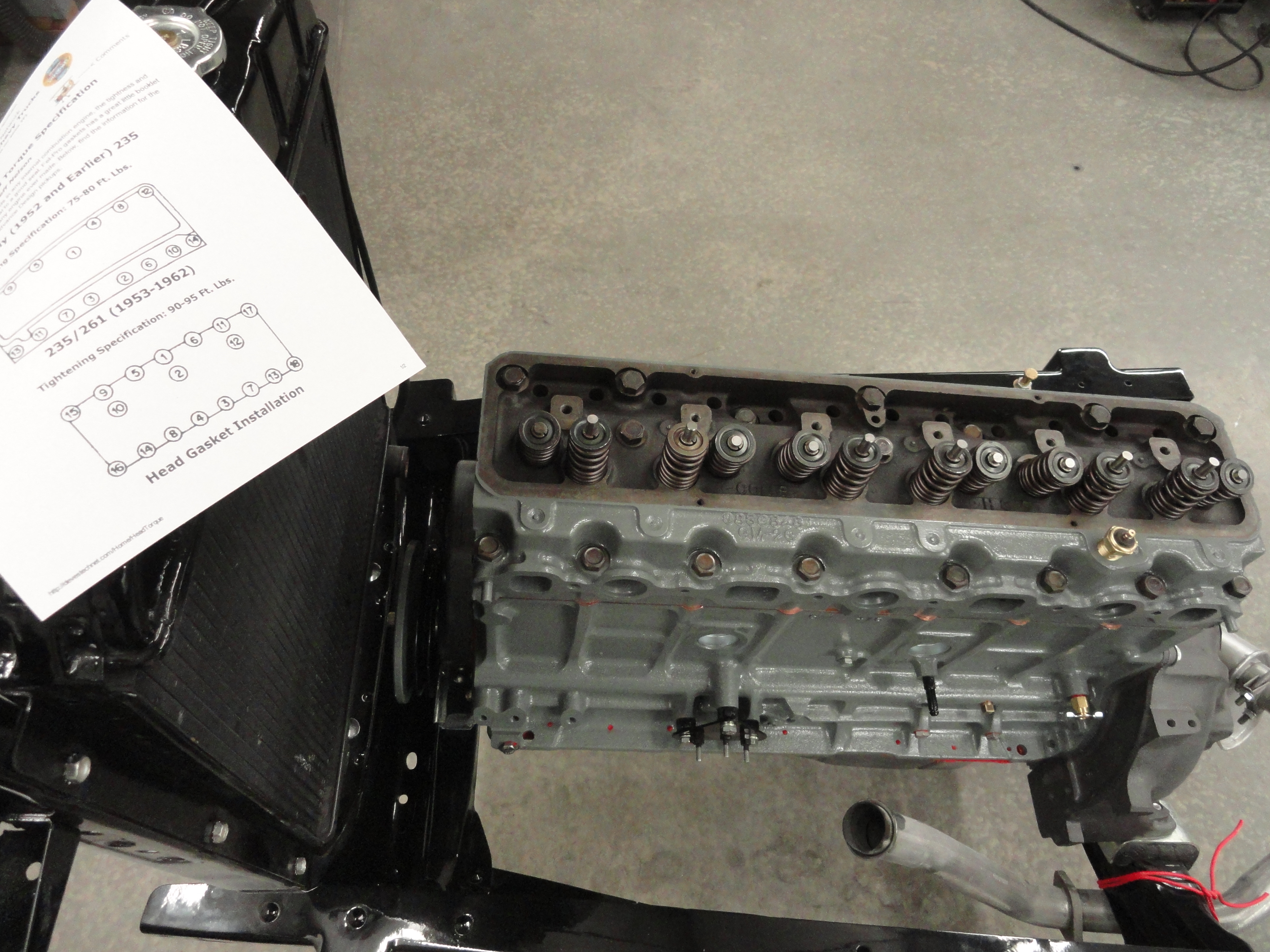
The Copper Gasket out of the Fel-Pro kit required Copper Gasket Sealer Spray in the aerosol can. Available at most auto parts stores, this stuff sprays on sticky but much like rattle can paint. You just need an nice even coat on both sides. Lay it back down observing the proper orientation, over the guide pins and you are ready to set the head down. I would use gloves if I were you. It's hard to get your fingers out of the way. Once the Head is set down properly and you feel good about it, start putting the Head Bolts in place hand tight. There are only two sizes, tall and short, so it will be obvious to you where they go. This is a good time to go get a printout of a document that is elsewhere on this web site. Years ago, Jeff Nelson created this really nice specification for me and it has become indispensable for getting it right. Set your 1/2" Drive Torque Wrench to 30 foot Pounds. For this particular engine, we will use the very bottom picture HERE. Once you have tightened them down to 30 foot pounds, reset your wrench to 60 foot pounds, do it all over again, then reset to 95 foot pounds and do it for the last time. This is a critical step so take your time and you will be very happy with the result. I know Jeff wants a warm engine to do the final torque, but in this case I don't have one and I want the gasket sealer to set with it at 95 cold. I will re-torque with a warm engine later.
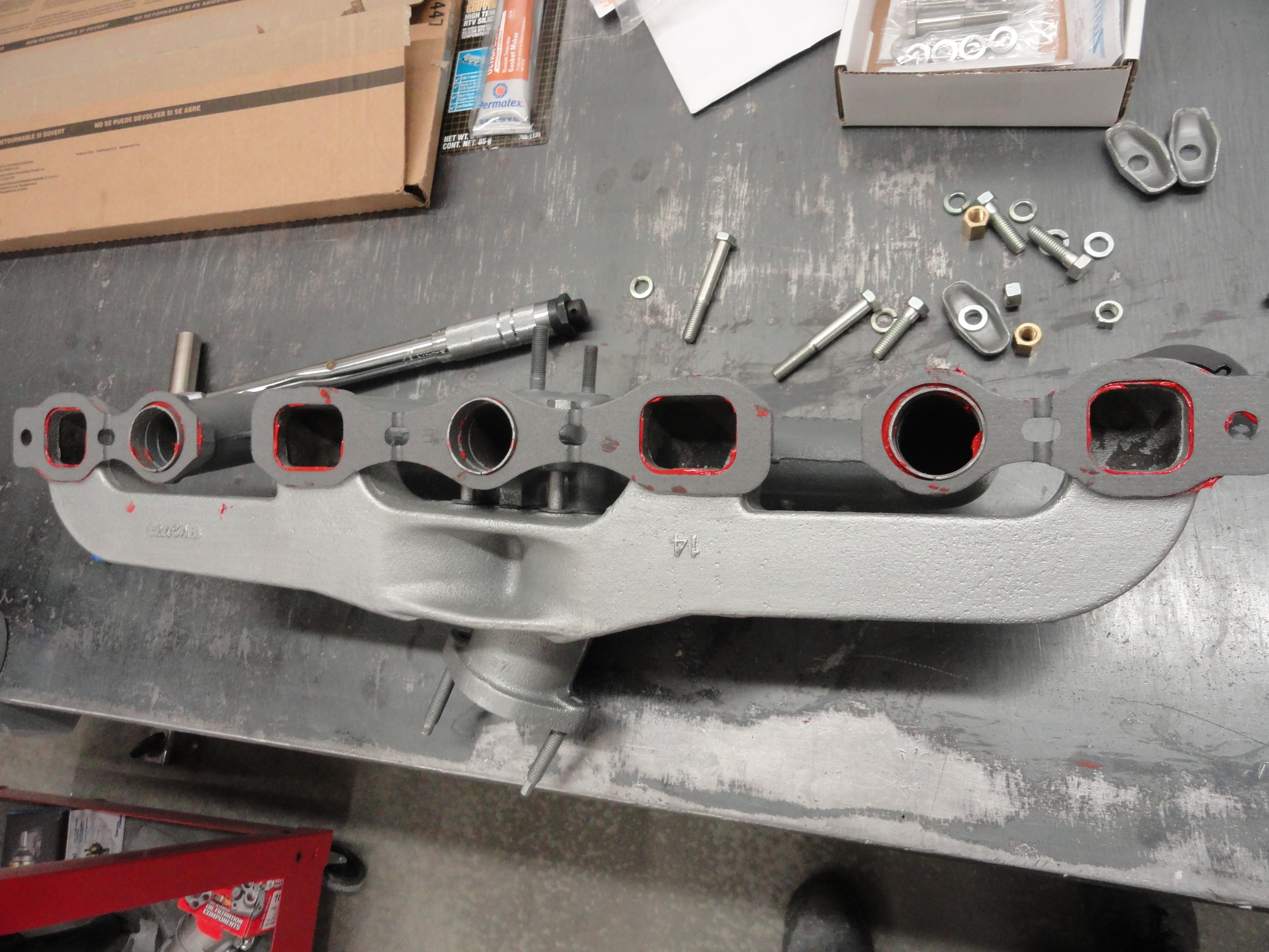
The Intake/Exhaust Manifold is next on the list. This can be a real bummer or it can be really easy. You MUST have those three guide rings for your Intake Manifold to set correctly. They are an integral part of the assembly. If you do not have them, our vendors sell them so please wait until you do! Slide these three guide rings into the manifold until they stop. As you can see, there is a place for them. Take the three sections of gasket out of your gasket kit and using high temp copper gasket sealer, paste them on to the manifold set with the metal side towards the manifold, not the engine. At this point if you have already bolted the Intake and Exhaust together, remove the bolts/nuts and install the gasket included in your kit. Metal side towards the exhaust. Now put the two back together using the proper bolts/nuts but leave them very loose. This is essential! At this point, I put gasket sealer on the exposed side of the gaskets as well. I then take the two bolts that will go on the outside-most part, which is also the two short hold-downs, place the assembly on the guide pins with one hand, and with a rubber mallet, tap the three guide rings/assembly into place. Once everything is happy, bolt it all down using the rest of the hardware. Tighten the intake to the exhaust at the same time you do the final torque on the manifold-to-head bolts. You can take the time now to install the exhaust flap spring and place the carb riser and gasket. If for some reason you mess up the gaskets and need a replacement set, the Fel-Pro part number is MS-9193B.
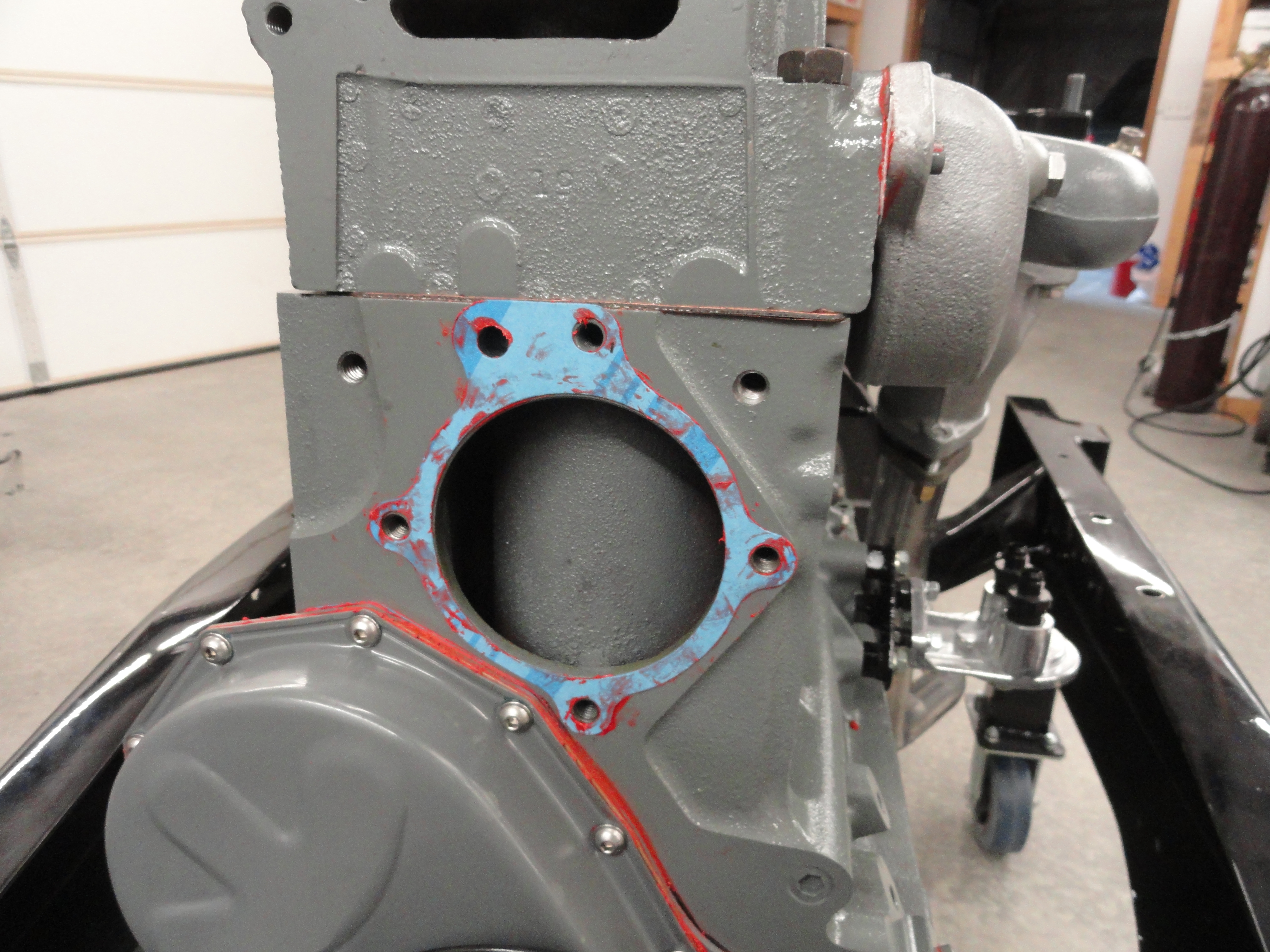
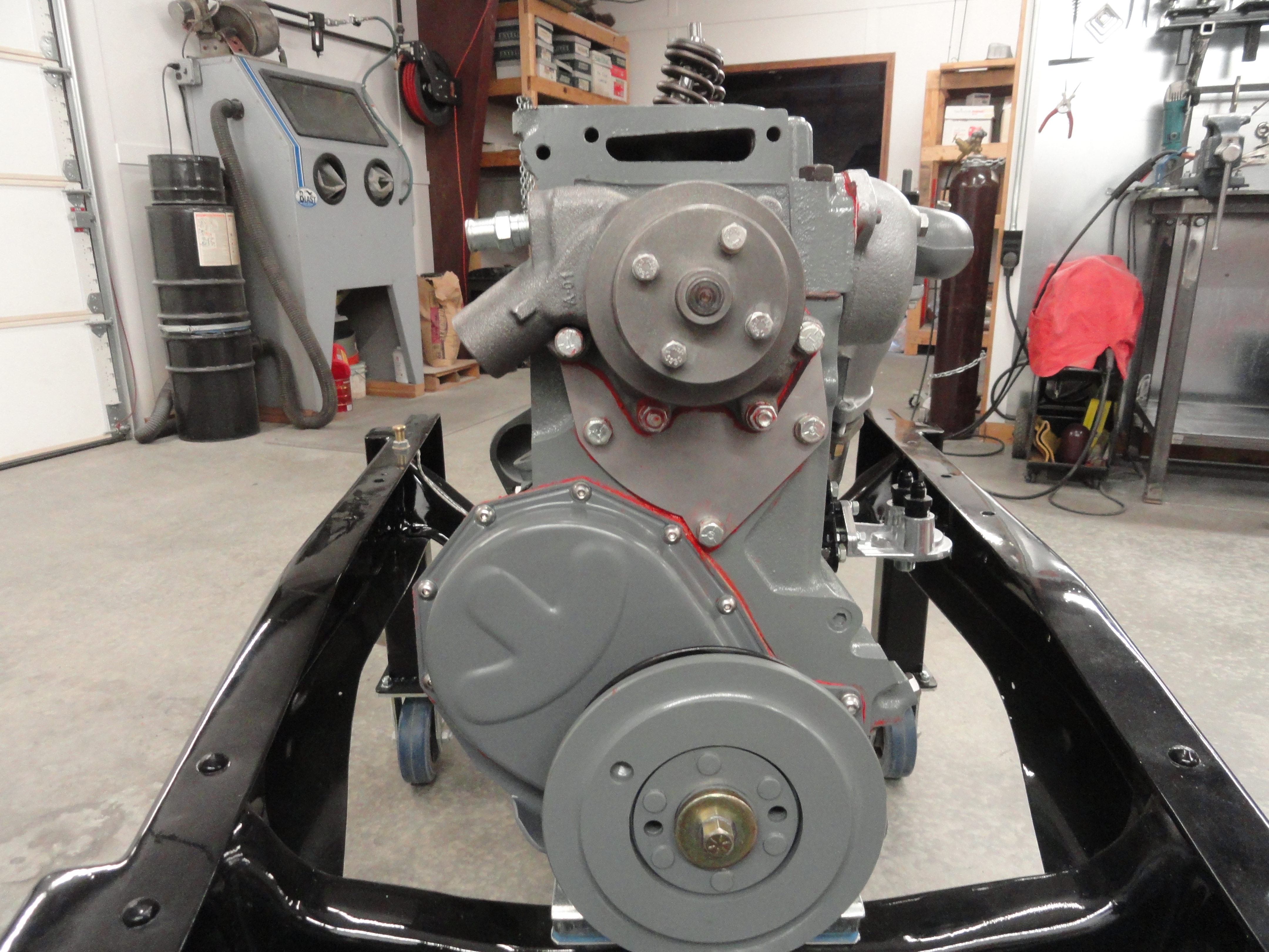
Next thing on the list is to install the water pump. As I said before, the 1954-1962 235/261 engines do not place the water pump in the center of your radiator like the older 47-53 216/235 engines did. This can lead to poor cooling and more unwanted heat stress on the engine. To avoid that, we use a water pump adapter with a specific 1953-55 water pump. Get the water pump gasket out of your gasket kit as shown. Earlier in this document I described how to locate, drill and tap the two extra holes needed for this adaptation. You will need to remove the old plate from the water pump, keeping the gasket. Use gasket sealer and seal the new plate to the water pump using the same two inset Phillips screws that came with it. To secure it near the bottom of the water pump, put two bolts with the nuts facing the outside just below the crescent shaped opening. Use lockwashers on the nut side and tighten them securely. Put Sealer on the outside of the gasket that is on the block in the above picture, then using 4 bolts, tighten to 35 foot pounds. Do NOT over-tighten the two that you tapped! You do not want to warp the plate. Just be sure it is snugged down tightly to the block. Dave, the maker of the Adapter Plate gives very good instructions on exactly how to do this complete with a pictorial representation. Go by that and you can't lose. It comes with the plate when you purchase it.

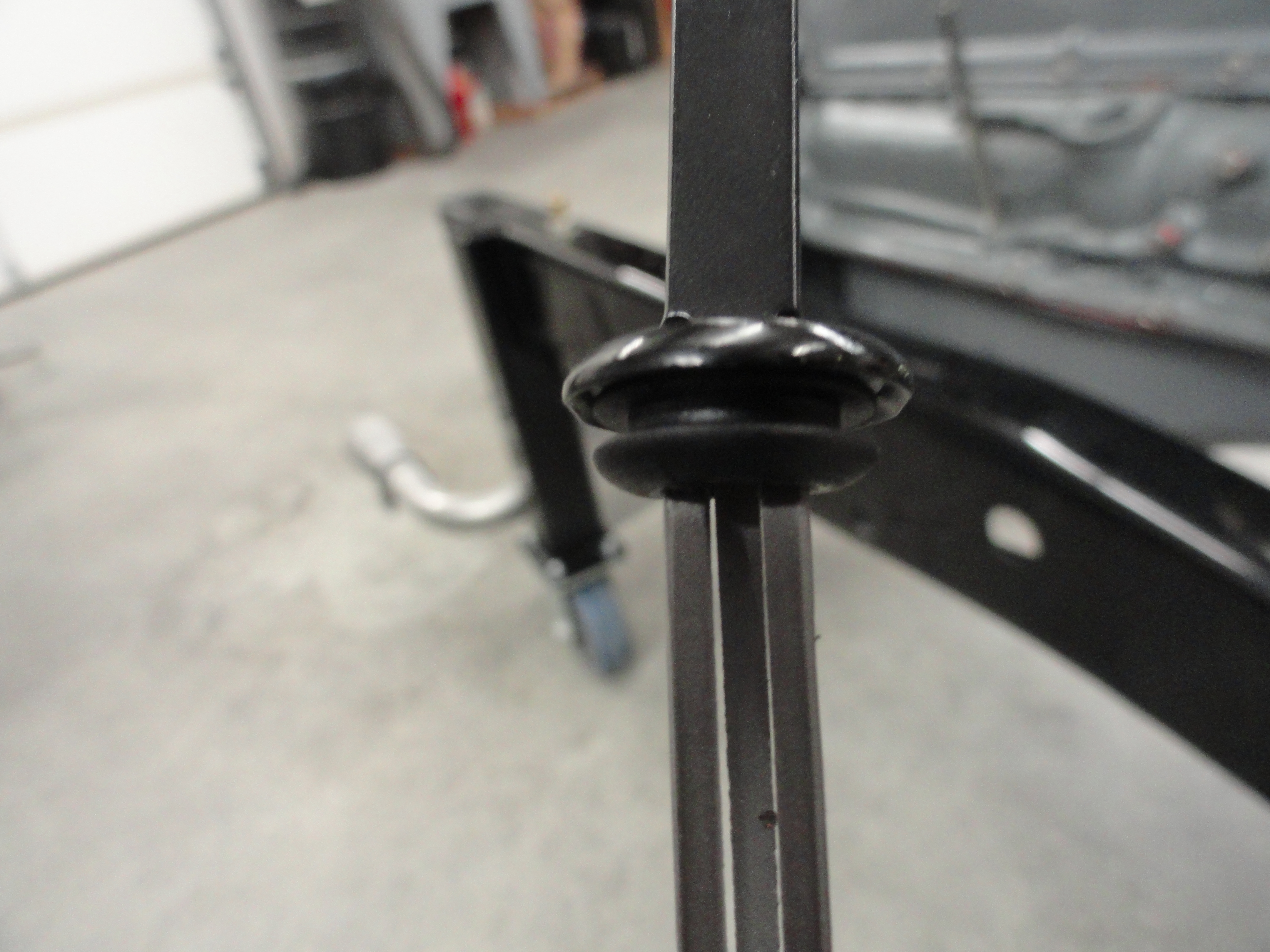
Now you can install your carb using the black riser block and then the gasket under it. There is a vacuum orifice on the mounting face of the carb and a corresponding notch in the gasket. The riser block itself has notches but in the wrong place. It is imperative that the vacuum orifice is clear and able to do its job, so I notched out the riser to match the gasket with a Dremel tool. It's these little things that will save you from misery later! You can also install the spin on oil filter adapter and the alternator brackets. Also there is the thermostat housing assembly, dipstick tube and while you are at it, you can slip a 3/8" rubber grommet on your dipstick to help seal the opening during use. Now is a nice break where we can just look things over and do the small stuff. I had to cut some mounting bolts to length to install a few things. I had to do some modification to the alternator bracket to accommodate the 3/8" bolts, etc. Install the Fuel Pump using the gasket that came with the kit. Don't forget to put some assembly grease on the pusher arm of the fuel pump before installing. This keeps the cam from galling right away. The next step of the process will take some thinking and pre-planning.


Valve Adjustment Procedures can be very intimidating. I hope to change all of that here for Hydraulics. No matter which style lifters you have, this will hopefully be a good read, then you can go HERE for a better understanding of how to do solid lifters. Everything you need for the Hydraulic ones will be explained right here. First thing to do is to use Assembly Lube liberally and get inside the lifter bores, the lifters, including the bottom of them and install all twelve lifters in their places. With the rocker assembly removed, place all twelve lifter rods in place through the appropriate holes as shown. Rotate the lifters around a bit and get them happy with their new home. My machine shop checked my old lifters and decided you can get new ones for the same cost as grinding the old ones. There is no need to take them apart and put oil in them. They will pump up almost right away during operation, and it is not needed for a proper initial adjustment anyway. In fact, we haven't even put oil in this engine yet! The idea of this initial adjustment is to get us very close so we aren't so hard on the engine. Once we have it initially adjusted, we will go back later and do these same steps again with oil in the engine and it warmed up.
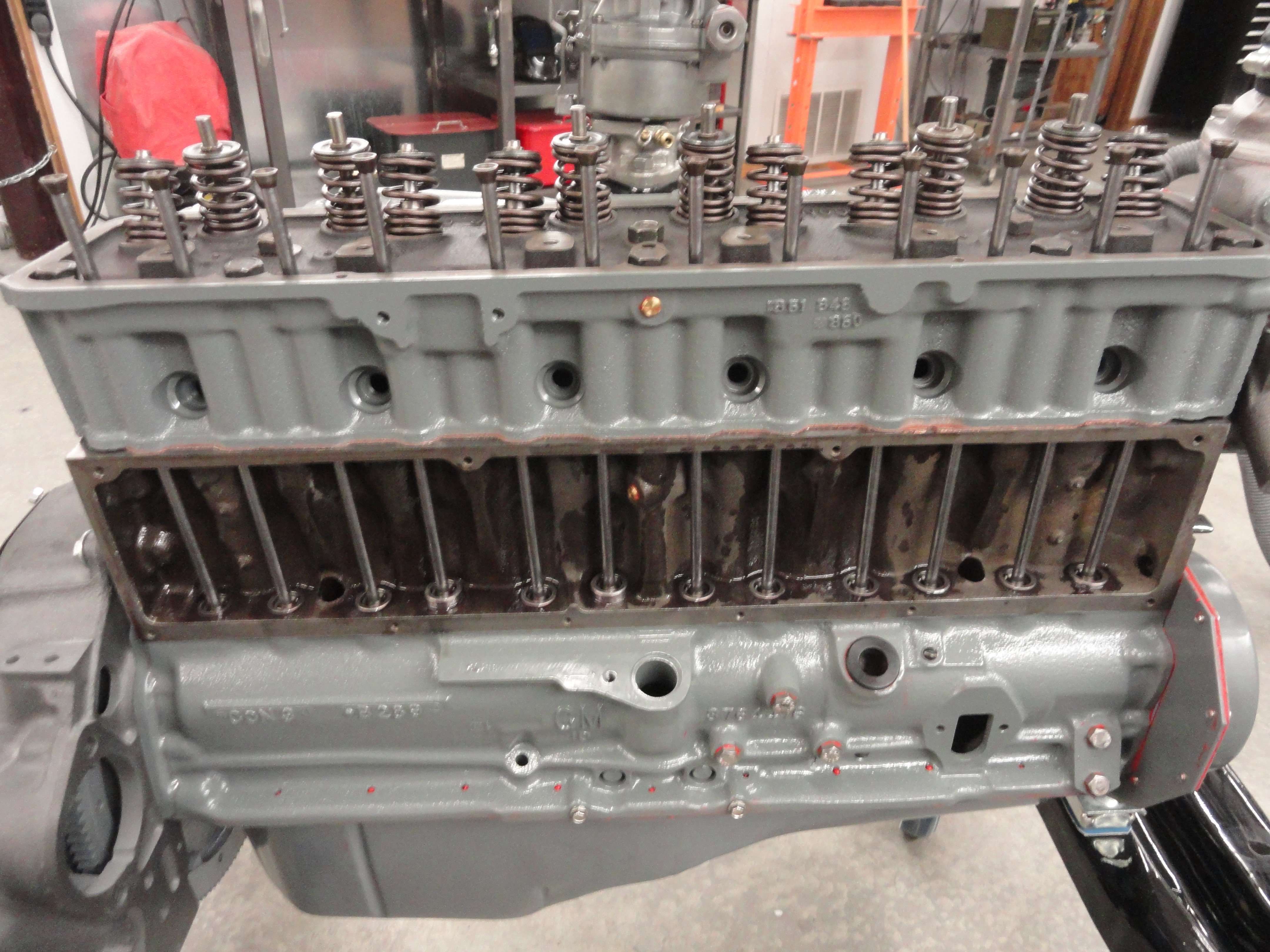
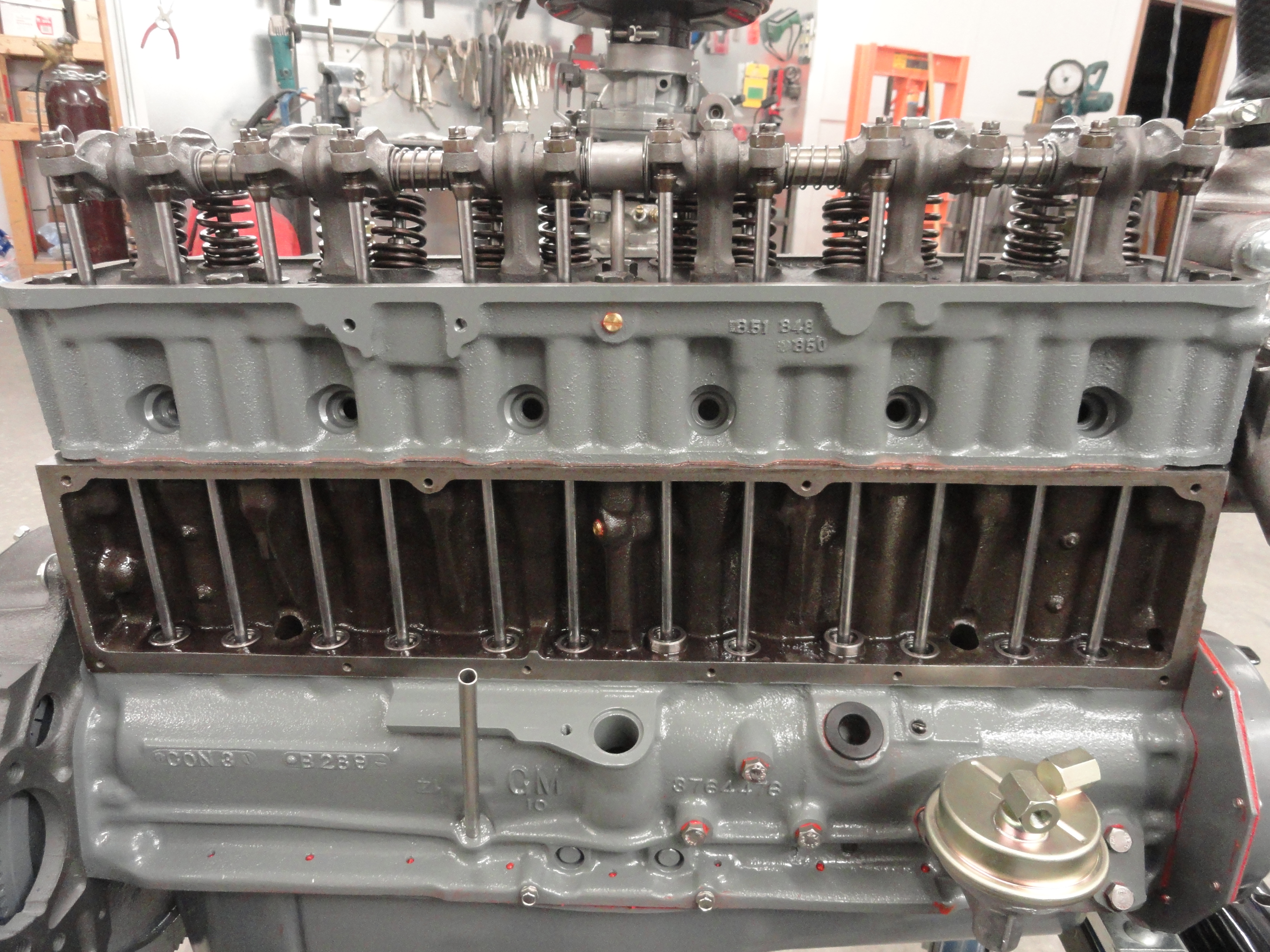
Loosen all of the adjustment screws on the rockers and back the rockers most of the way off so that there is plenty of adjustment available. Keep them loose for now. Install the rocker assembly on the head. I find it easiest to do it as a whole unit, making sure the center oil tube goes down into the head. Be sure to have it all pre-assembled correctly using the appropriate rockers, springs, washers, etc. There are pictures earlier in this document to help you get it right the first time. Tighten down the 6 assembly bolts making sure everything lines up. Do not bend the push rods and make sure to set each rocker assembly ball into the top of the rod before tightening. Lots happening here, so take it slow and easy. If you remember earlier in this article I showed you how to mark your flywheel. Each marking set was 120 degrees from the other. If you forgot, please go back and read that part. This is where it becomes a really good thing that you followed instructions! The flywheel only goes on one way, so we will use this to our advantage.
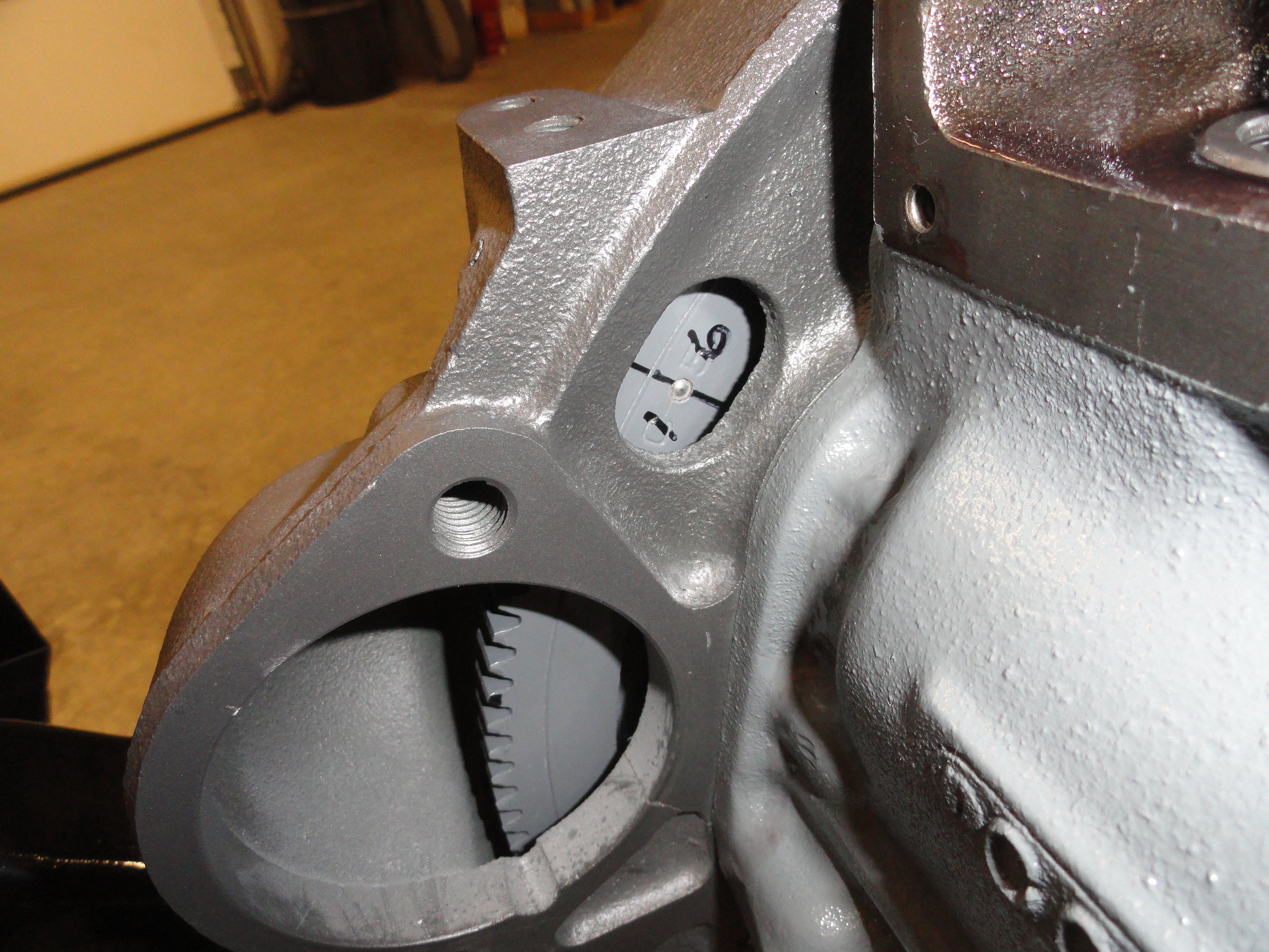
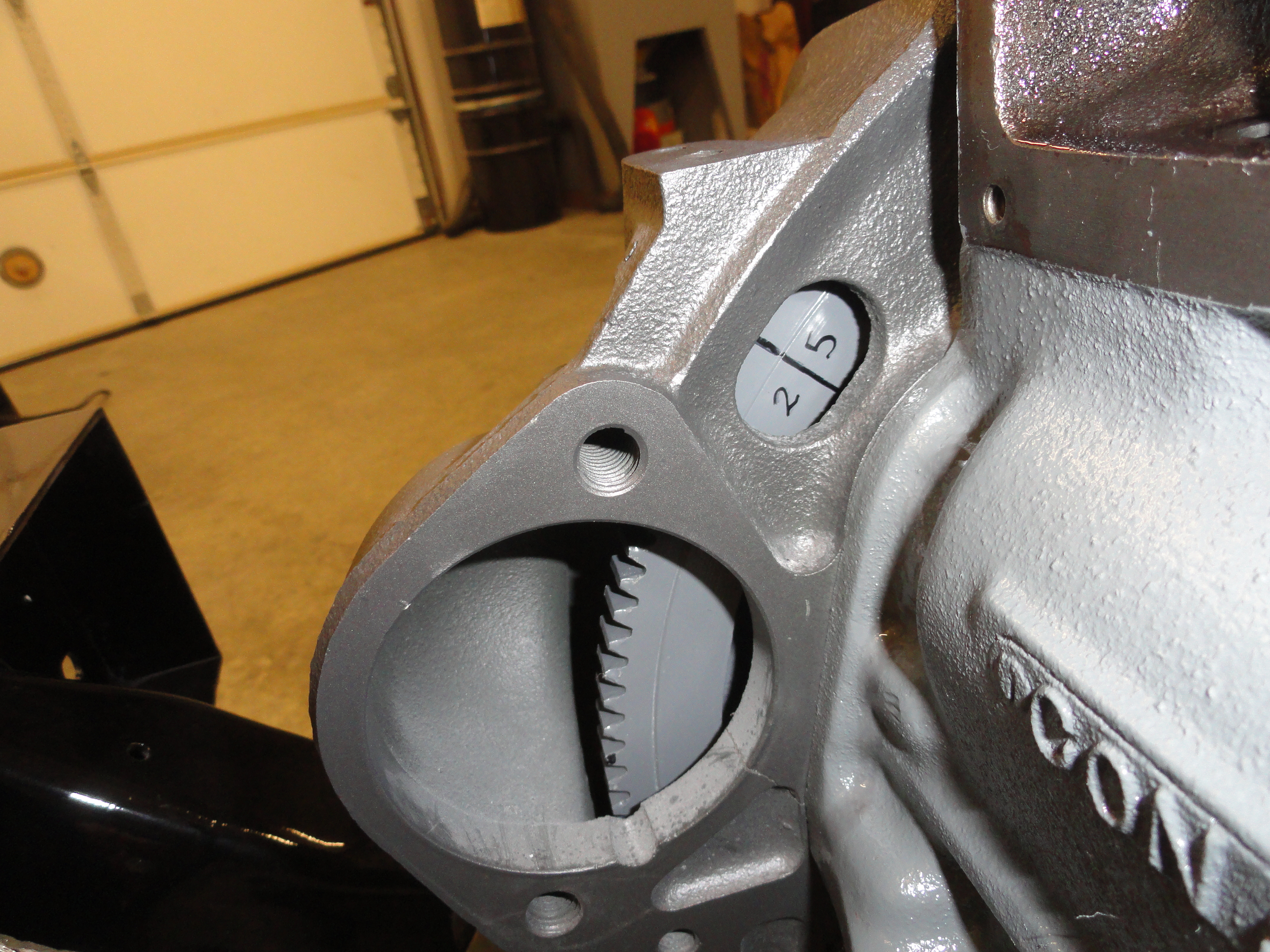
With the Head on the engine block there are only a few ways to determine when the pistons are at the VERY top of their cycle. One way is to stick a plastic
straw down the spark plug hole and hope you can gauge exactly where the top is. Another is to MARK YOUR FLYWHEEL! Another way is to install the distributor
properly, then look at where the rotor is pointing. I am not ready to put the dizzy in yet, so I am going to rely on the more precise Flywheel Method. Because
I had the machine shop drill my crankshaft for a 7/16" bolt to hold on the Harmonic Balancer, I have a very easy way to turn the engine. A 1/2" drive ratchet
and 5/8" socket is all I need to easily turn the engine with the spark plugs out. It is even below the radiator! So before we start, let's discuss some of the
theory behind the timing of these engines. When you turn your engine to where the BB is present in the window and 1/6 are present too because you marked it
that way, both the #1 and #6 cylinders are at the top of their cycle. (Arguably for you engine experts we know the U|C really is, but this is more than close
enough for the initial adjustment of hydraulics). The system works on a 720 degree cycle. So the first full 360 degrees of rotation fulfills the intake/exhaust
and firing cycles of half the cylinders, the next full 360 degrees of rotation fulfills the intake/exhaust and firing cycles of the other half of the
cylinders. So, it is not true that one rotation of your engine gets the job done. It's every two. To understand how intake/exhaust and then firing take place,
the cam has lobes and then on the back of these lobes is the base circle. This base circle is where firing occurs. So, how do we tell if our #1 cylinder is at
the top because it's firing, or if it's at the top because it is on the intake/exhaust stroke? Because the lifters are not moving on the firing stroke! The
lobe is 180 out and the cam is on the base circle or firing position. So, to test this, rotate the engine OFF of the BB about 20 degrees clockwise and then do
it counterclockwise the same amount while observing the lifters. Do they move? If they move, you are at the firing stroke for #6. If they do not move, you are
at the firing stroke for #1. We call this "Rocking" because one set of lifters for those two cylinders are "rocking" back and forth.
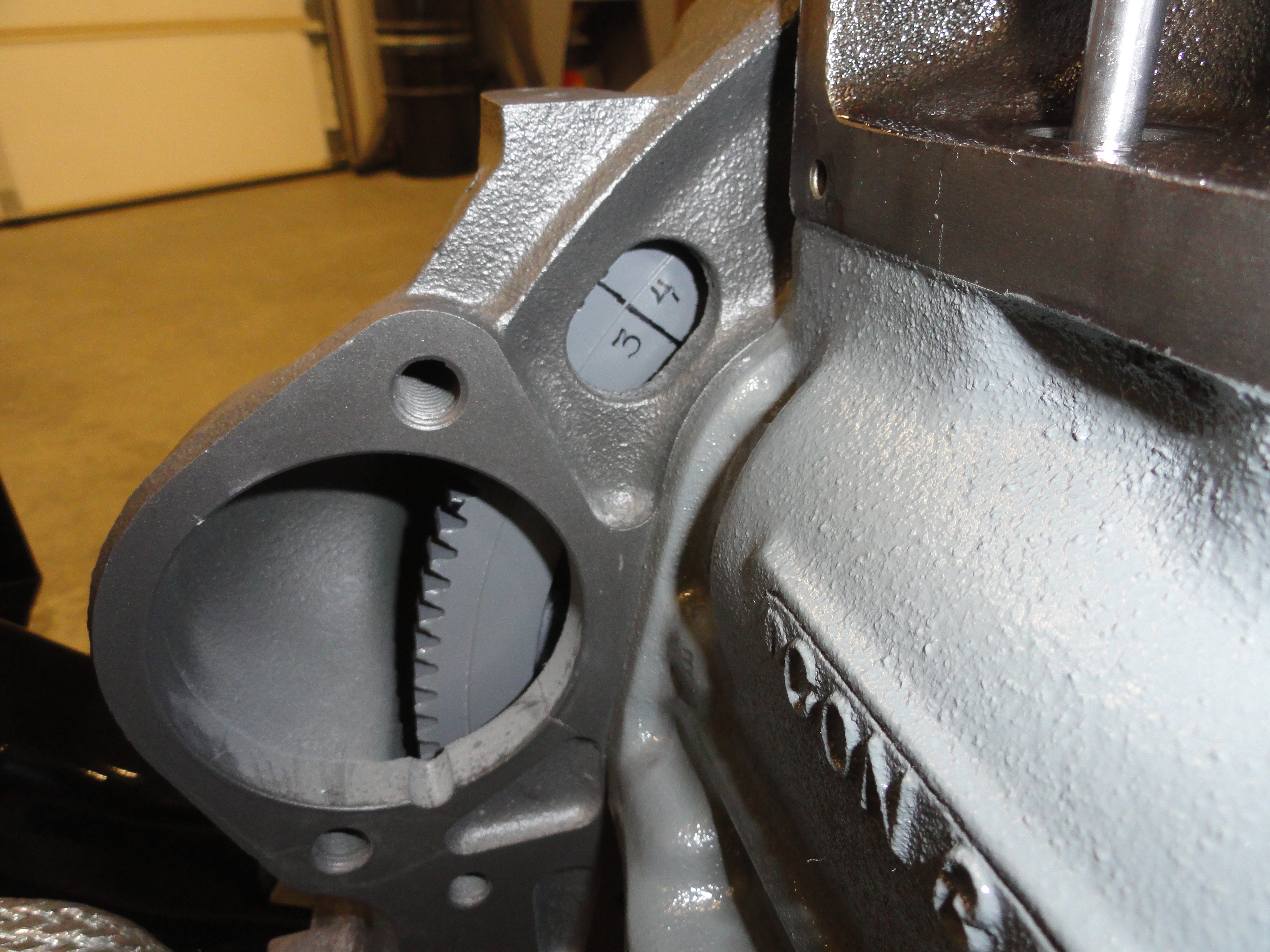
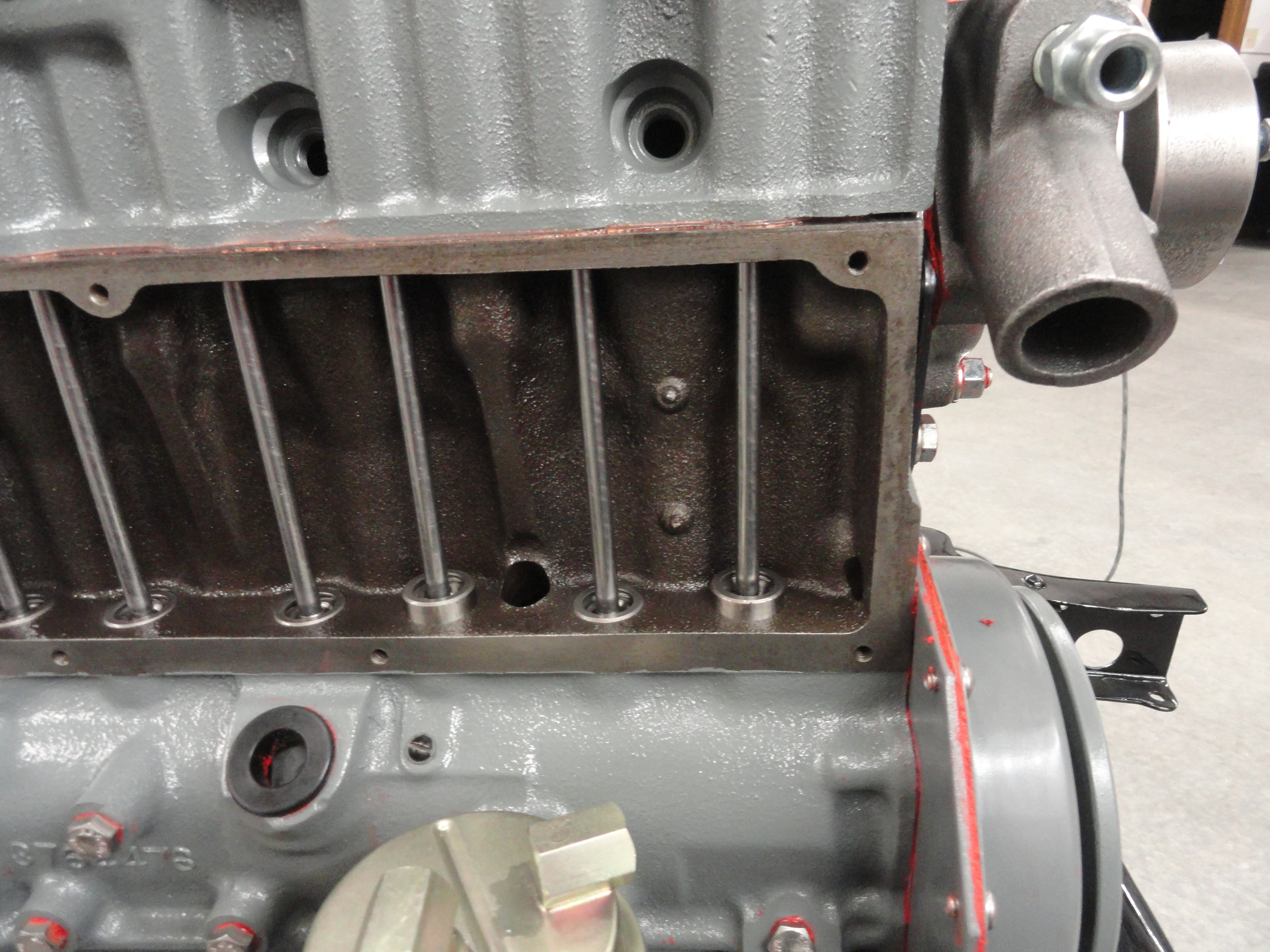 The biggest problem you are going to have in doing this is rotating your engine if you didn't opt for the bolt. The list below will help you figure out which
valves to adjust. We adjust the valves by using the slotted screw/lockdown on each rocker. Let's start by adjusting Number One Cylinder. Rotate your
engine to the BB and 1/6 marking. Move the flywheel back and forth 20 degrees to determine which set of lifters is rocking. If #1 is rocking, go another full
360 degrees. You will notice #1 lifters are not rocking but #6 is. This is the #1 firing position and where we need to adjust both intake and exhaust valves. The push
rods should be relaxed and not touching your rocker assembly ball at all really. Spin the #1 push rod you are adjusting in your fingers while screwing down the
adjustment. You will feel it get tighter when the ball of the rocker is up against the rod, and the rocker is up against the valve stem. At this point, turn the
screw another 1/2 turn tighter and lock it down. Keep the screwdriver oriented when you tighten so it doesn't move. DO that again for the other valve for that
cylinder. That wasn't so hard was it? Now you have just adjusted your hydraulic lifters for #1 cylinder. Here is the listing for the rest...
The biggest problem you are going to have in doing this is rotating your engine if you didn't opt for the bolt. The list below will help you figure out which
valves to adjust. We adjust the valves by using the slotted screw/lockdown on each rocker. Let's start by adjusting Number One Cylinder. Rotate your
engine to the BB and 1/6 marking. Move the flywheel back and forth 20 degrees to determine which set of lifters is rocking. If #1 is rocking, go another full
360 degrees. You will notice #1 lifters are not rocking but #6 is. This is the #1 firing position and where we need to adjust both intake and exhaust valves. The push
rods should be relaxed and not touching your rocker assembly ball at all really. Spin the #1 push rod you are adjusting in your fingers while screwing down the
adjustment. You will feel it get tighter when the ball of the rocker is up against the rod, and the rocker is up against the valve stem. At this point, turn the
screw another 1/2 turn tighter and lock it down. Keep the screwdriver oriented when you tighten so it doesn't move. DO that again for the other valve for that
cylinder. That wasn't so hard was it? Now you have just adjusted your hydraulic lifters for #1 cylinder. Here is the listing for the rest...
1/6 with 6 rocking, adjust #1
2/5 with 2 rocking, adjust #5 (1st clockwise rotation of 360 degrees)
3/4 with 4 rocking, adjust #3
1/6 with 1 rocking, adjust #6
2/5 with 5 rocking, adjust #2 (2nd clockwise rotation of 360 degrees)
3/4 with 3 rocking, adjust #4
NOTE: You can put your distributor in anytime you want, just go back to #1 firing position. (1/6 with #6 rocking).
To help you better understand this, if I wasn't able to do it for you, go back to that Valve Adjustment Procedure I mentioned earlier in the How-To section
of this web site. Nate and Jeff can help you better understand if I couldn't. Now that you have the valves adjusted properly, you can button up your side
cover and move on. Another very good resource if you are having problems with Hydraulic Lifters is
Dave's Blog. We will be addressing the concerns
mentioned in Dave's Blog at our second round of Valve Adjustments. This initial adjustment is necessary for us to get to initial startup.
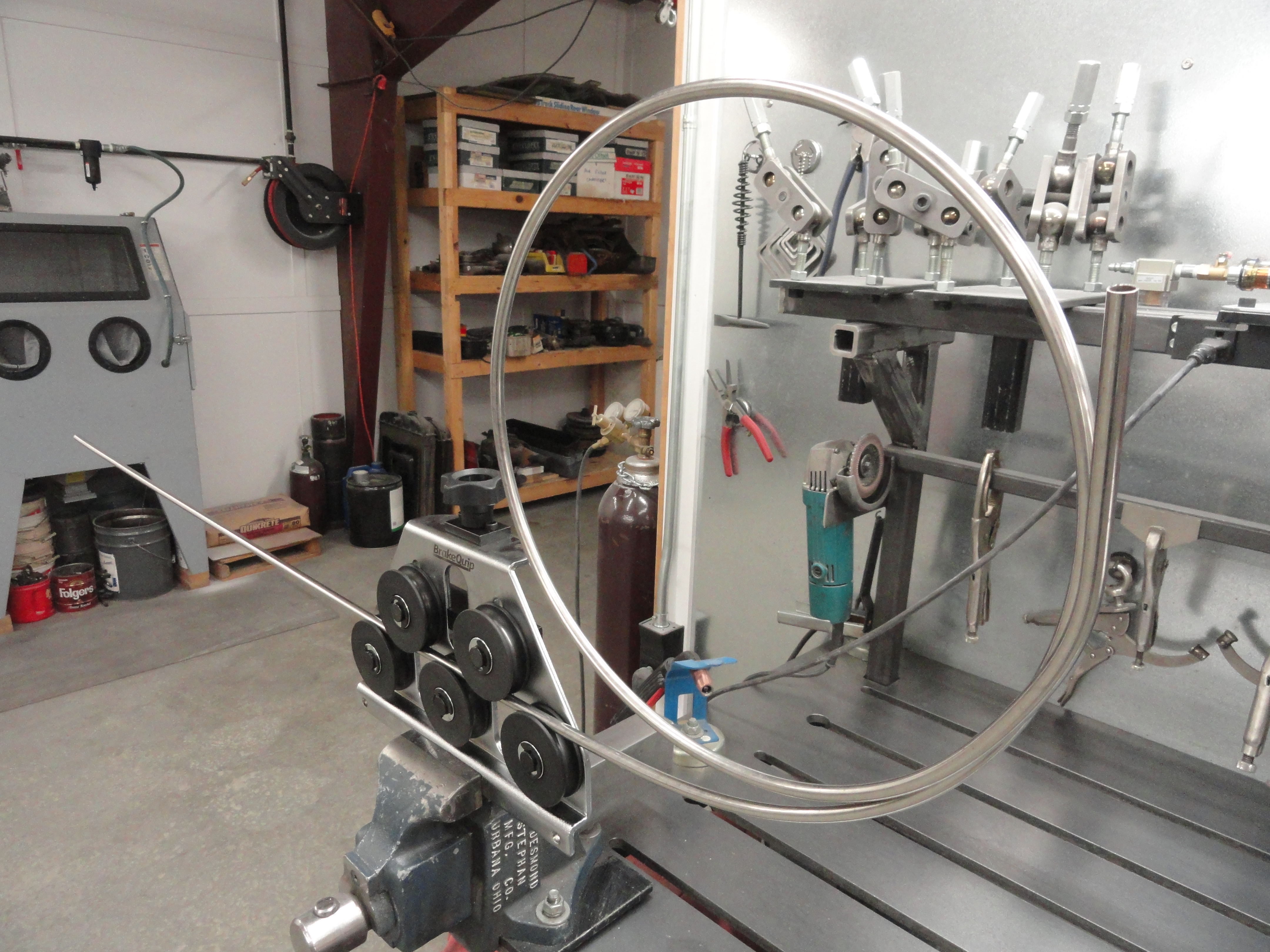

At this point, you have about 90% of the work done but there is more to do. We need to bend us up some hardlines for PCV, Fuel, and Vac Advance. I use a tool that is the best I have ever seen for all of this. It's the BrakeEquip BQ351. I am also sold on stainless steel for the lines. It's the last time you will ever have to service those lines. It's very hard to bend this stuff and I purchase it in 20 foot rolls. Then, you have a new problem, you can't straighten the stuff, so I also have a BrakeEquip Tube Straightener (pictured) and a BrakeEquip Tubing Bender that is fully adjustable for all sizes in one tool. I know it seems they saw me coming, but I just can't believe how easy it is to do tubing now. The hardest part is thinking about where you need to cut, bend, shape, etc.
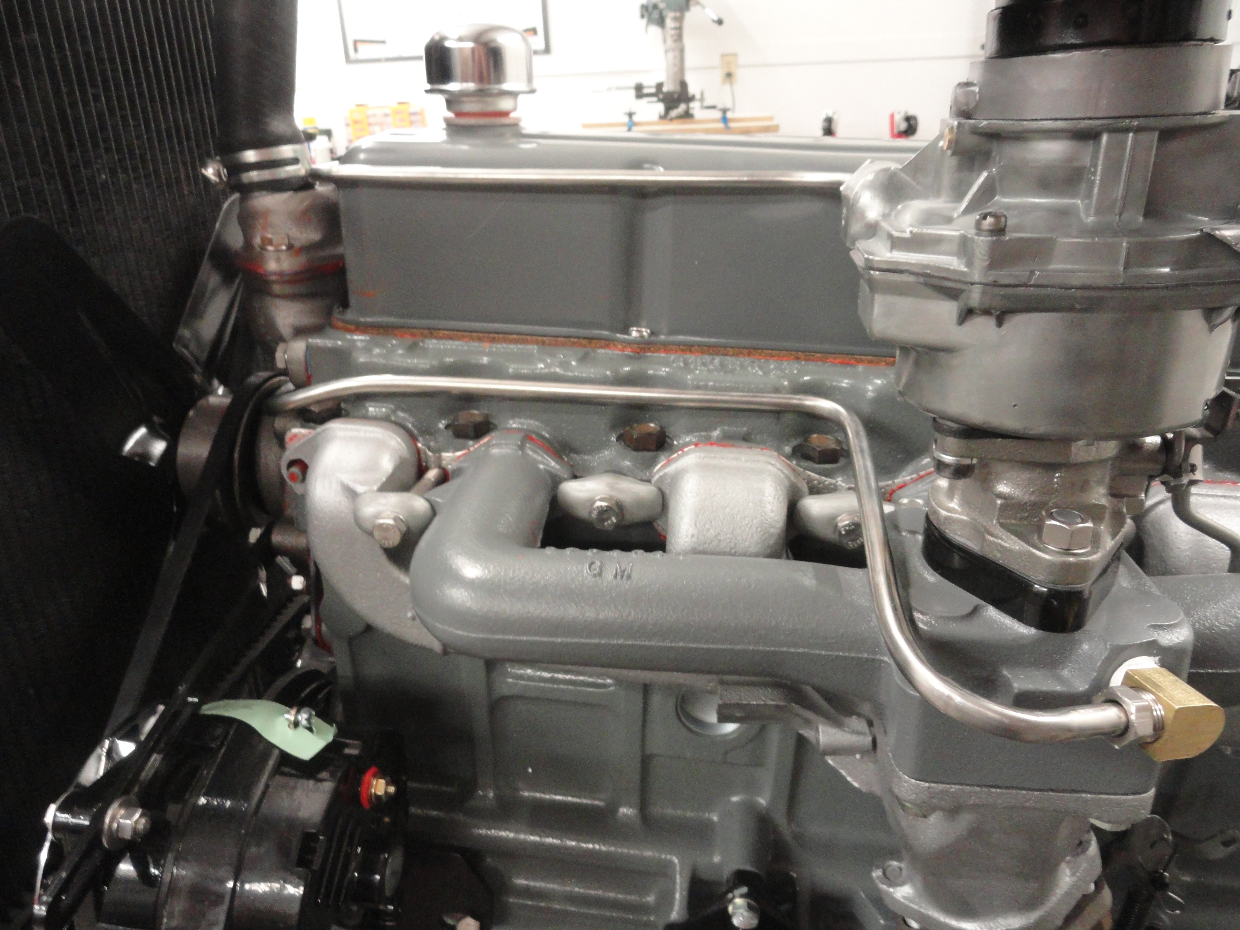
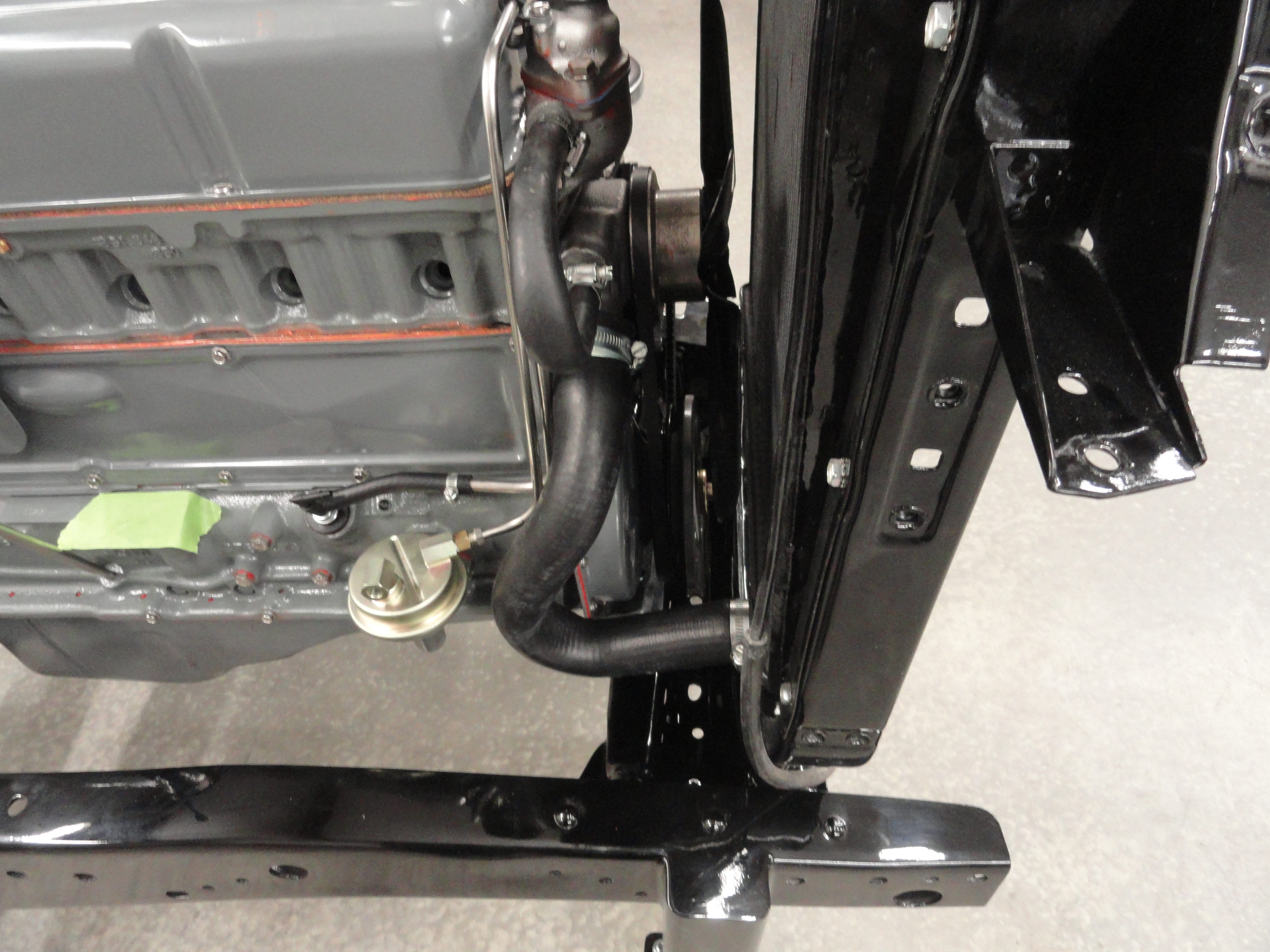
With the water pump adapter in place, there happens to be about 3/8" of space I used to bend the PCV hardline into. This seemed the most elegant way to do it.
Of course, you don't have to use hardlines, but rubber breathes and since I am testing PCV valves with this engine to determine which one is best suited for
our engine, I didn't want to have any anomalies crop up. Since I used a newer style Rochester B, the placement of the fuel line is different, so I made the
correct profile 5/16" fuel line. The Vac Advance line will be bent to follow the fuel line as much as possible. The tubing bender comes in really handy for
all of this. It has a tab that you put in the vise to hold it, and an Allen set screw for adjusting the thickness of the tubing you are working with. The only
problem I have with it is that it doesn't have an index or any way for me to tell how far to bend. Takes some getting used to.
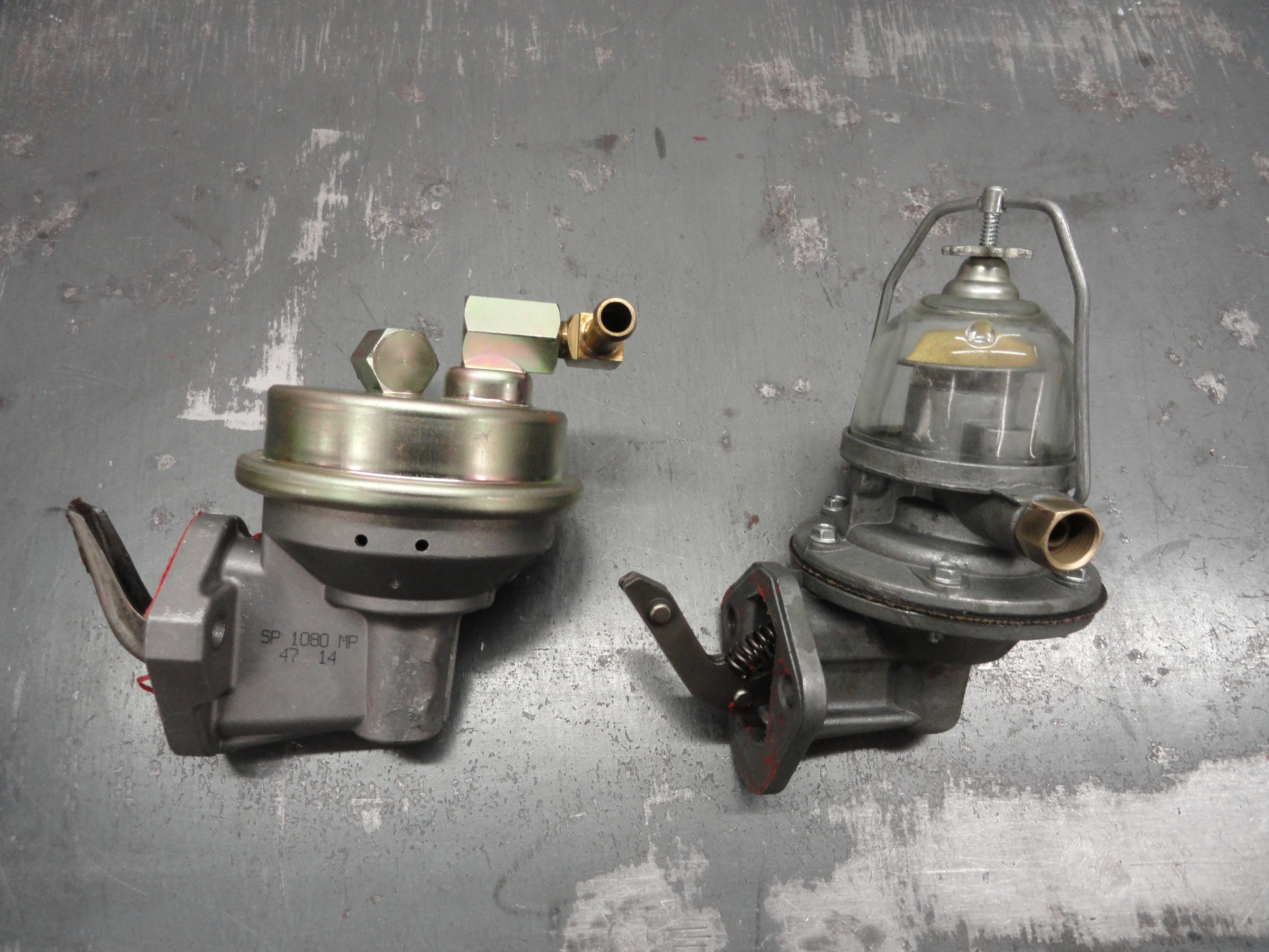
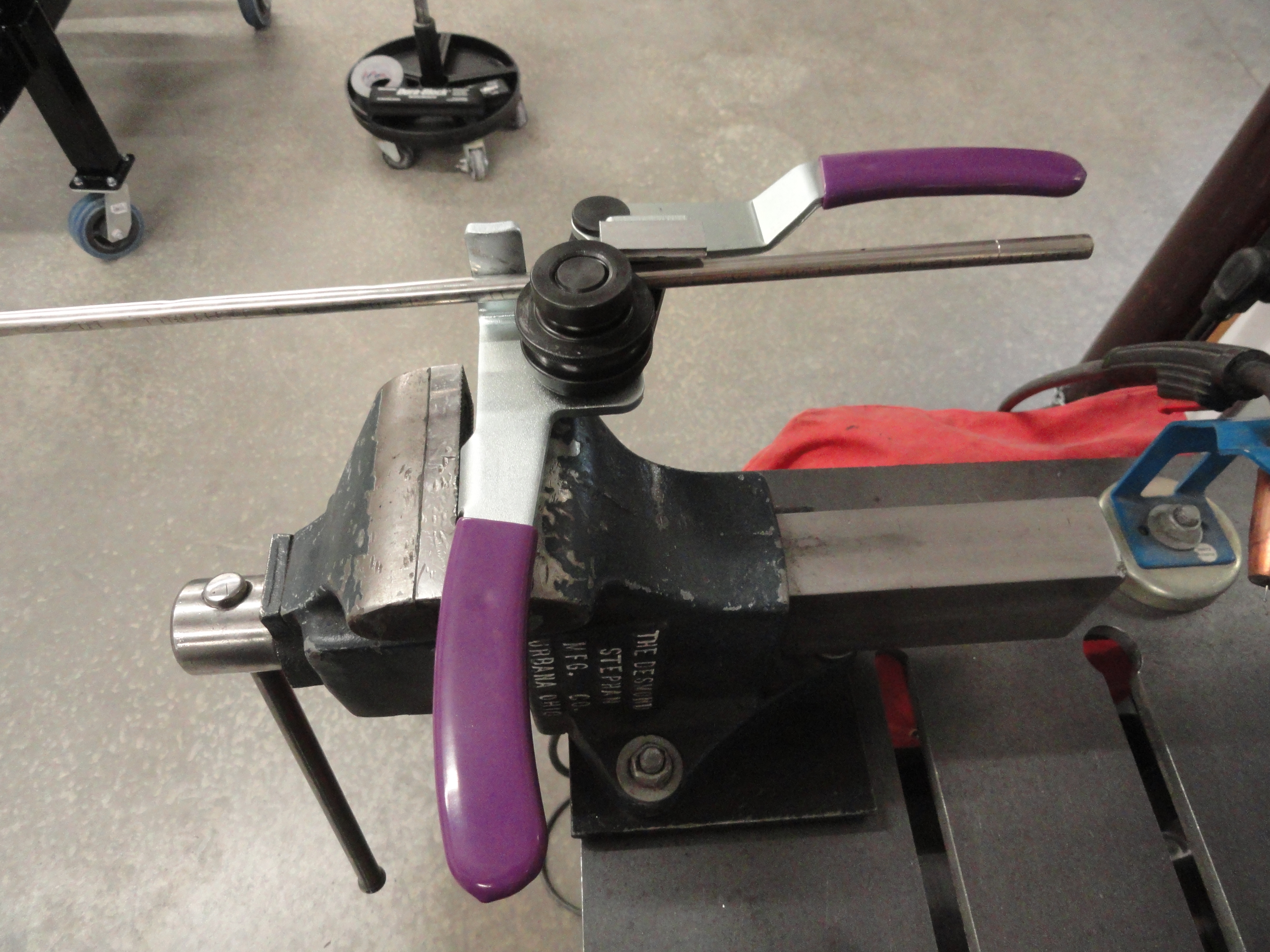 The fuel pump I got for this project is the year correct one, but I do not like that the inlet and outlet isn't across from each other. So I opted for a
vendor supplied glass bowl type. The glass bowl type has connections across from each other and for a test engine, it enables me to see the fuel. Because
when you order from an auto parts store these days, you never know which style you are going to get (inlet/outlet wise), I would suggest taking the time to
make a few adapter lines so when you order a fuel pump for your 235 engine and you get the other style, you can still use it by taking those two adapter
lines out of the glovebox.
The fuel pump I got for this project is the year correct one, but I do not like that the inlet and outlet isn't across from each other. So I opted for a
vendor supplied glass bowl type. The glass bowl type has connections across from each other and for a test engine, it enables me to see the fuel. Because
when you order from an auto parts store these days, you never know which style you are going to get (inlet/outlet wise), I would suggest taking the time to
make a few adapter lines so when you order a fuel pump for your 235 engine and you get the other style, you can still use it by taking those two adapter
lines out of the glovebox.
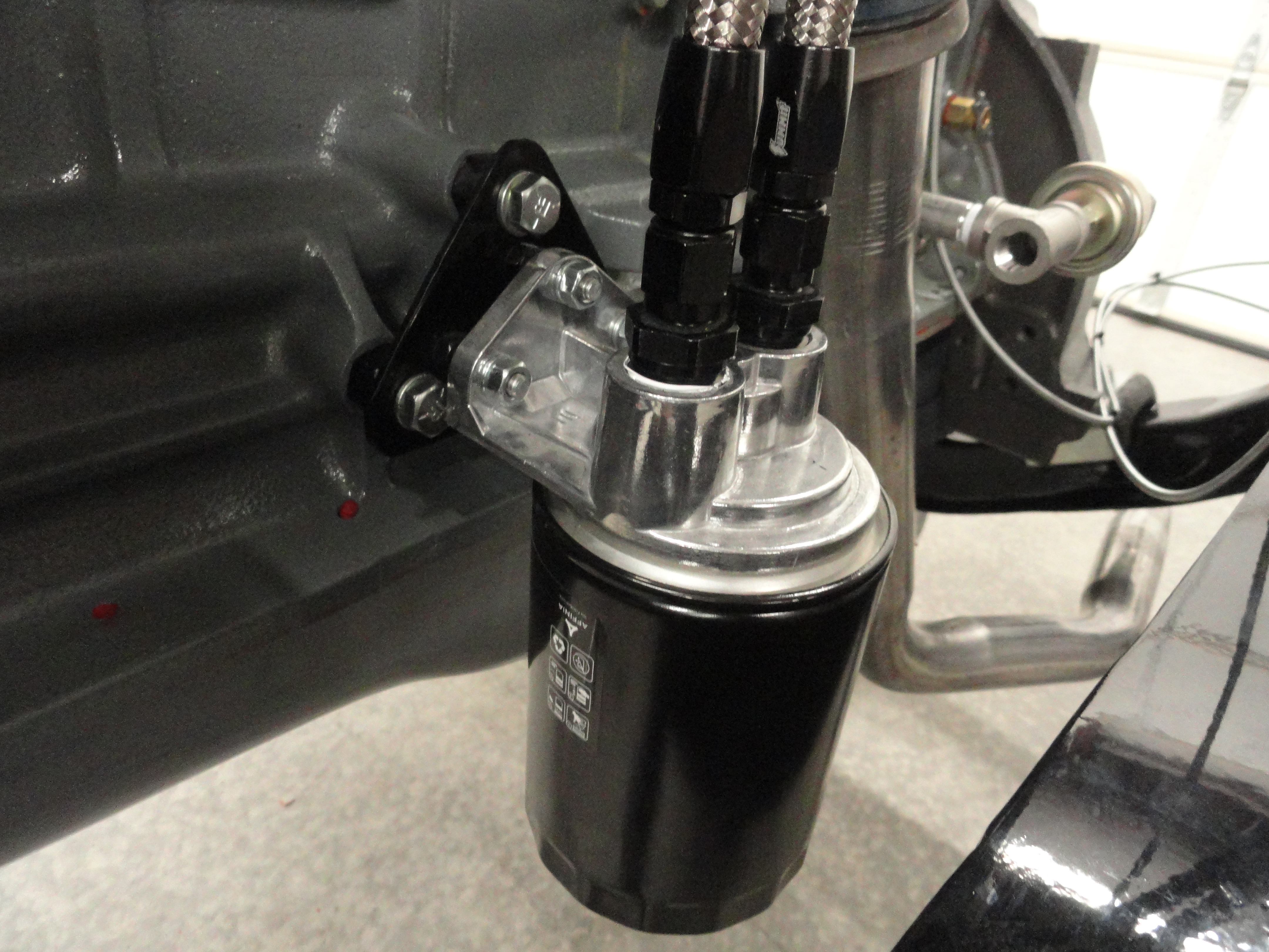
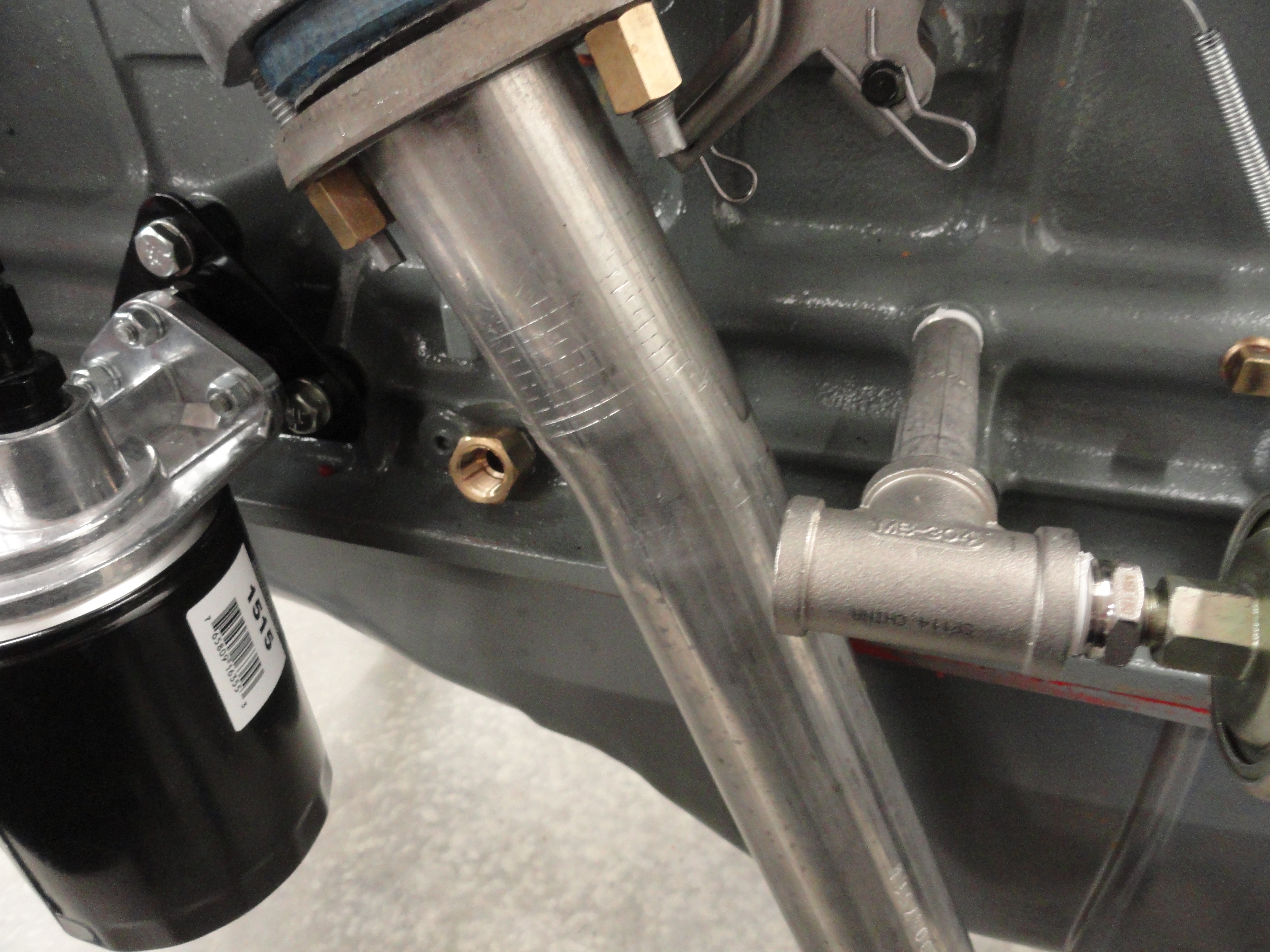
This engine is very special in that it is a Sealed system. The road draft tube is replaced with PCV, the valve cover cap is replaced with a filtered and vented cap, and we are using a full flow modification for our oil. These engines were notorious for gumming up the rocker assembly and causing no flow to the rockers or valves. This can be avoided by filtering 100% of your oil and closing it to any outside dirt as best we can. The oil lines that come out of the block are now (after the machine shop modification) 3/8" NPT. I added a brass 3/8" NPT extension on the Oil Pump Outlet to get it away from the engine block, then added a 4 inch 3/8" NPT Stainless Pipe with a Stainless 3/8" NPT Tee Connection. What this does is moves the rubber/stainless lines away from the hot exhaust and also gives me a very nice Oil Pressure Gauge connection. That is done with a 3/8" NPT to 1/8" NPT adapter on the gauge end of the Tee.
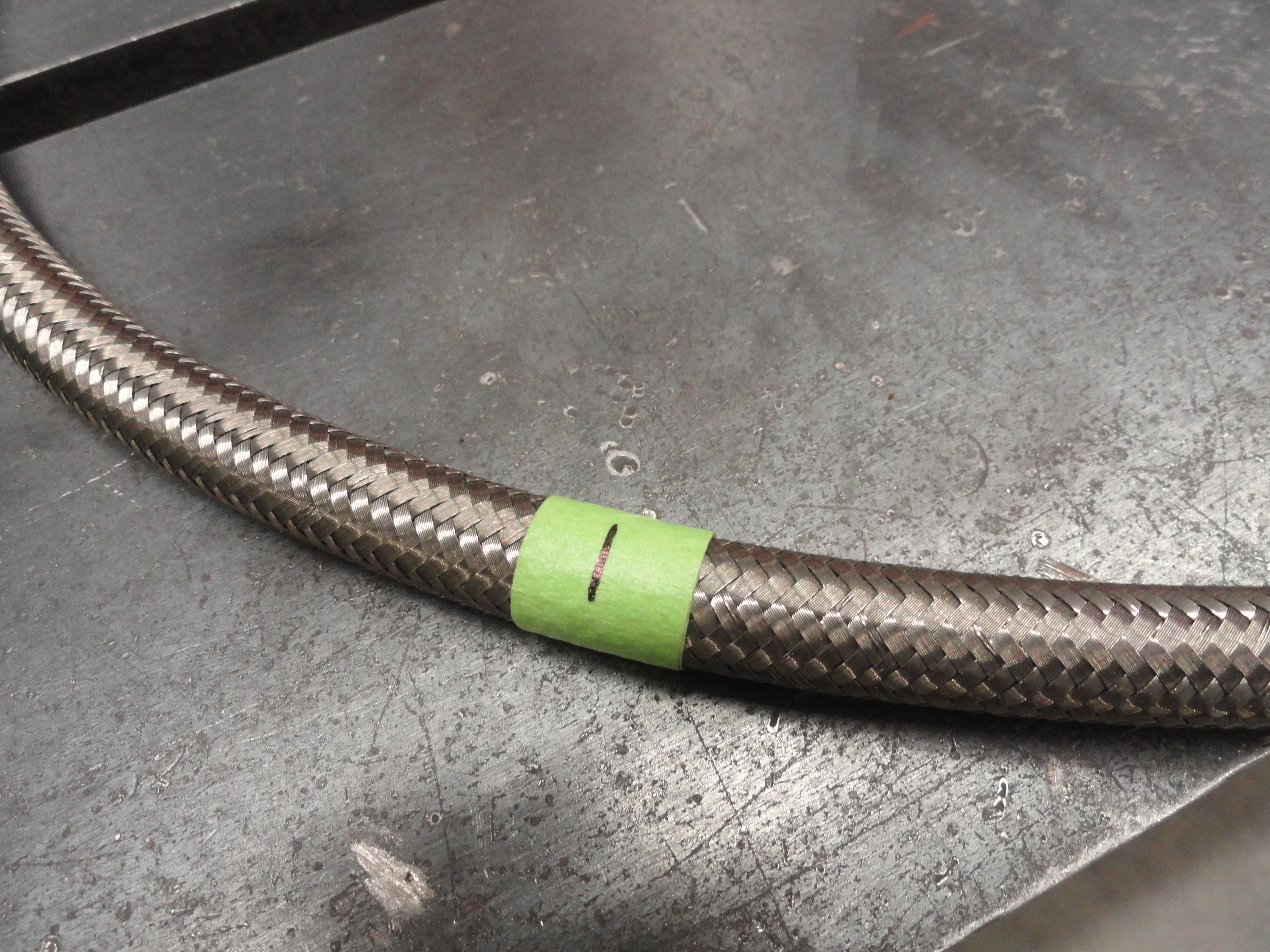

I decided to go with Stainless Braided Rubber Hose made for this purpose. You can get it at Summit Racing in any length you wish. The best connectors for this purpose are the -6AN connectors shown. You simply get adapters for the TransDapt Spin-On Filter Adapter to go from the 1/2" NPT it already is, to -6AN. The -6AN is what you use for 3/8" NPT adaptations. These connectors eliminate the worry and any thought that maybe the connectors might come loose during driving. There are a few tricks to doing this right however. The first one is knowing they come apart! Once that revelation is behind you, there is the trick of how to cut this braided stuff and have a smooth enough edge to get the connector on. Oh trust me, this is THE hard part! So, measure the length of hose you need and then put a good tight 2-3 rounds of masking tape around the center of your mark. This is to keep both sides of that tape tight so the stainless doesn't just unravel on you. Next put a thin cutoff disk on your Makita grinder and make the cut. Go slow and easy, turning it as you cut through to the rubber so there are no loose ends. Once its cut, you can remove the tape and screw on the connector.
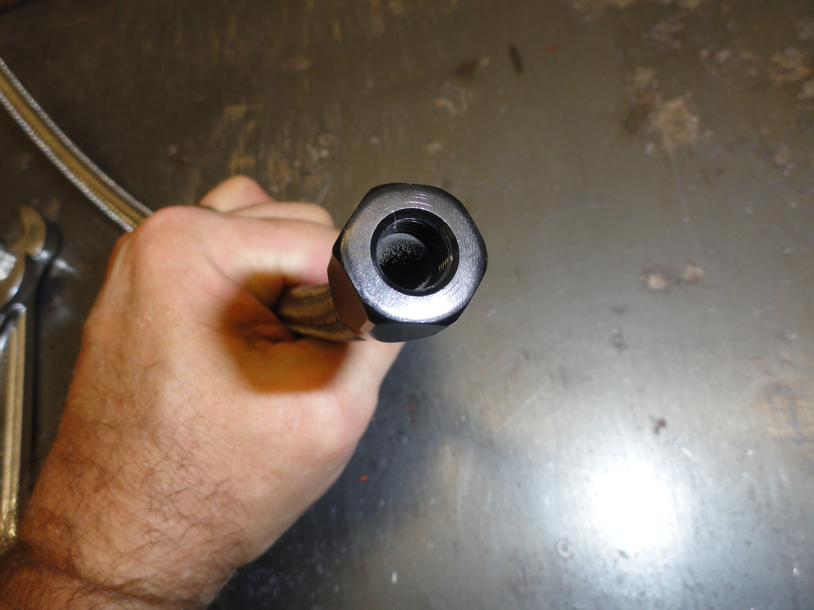
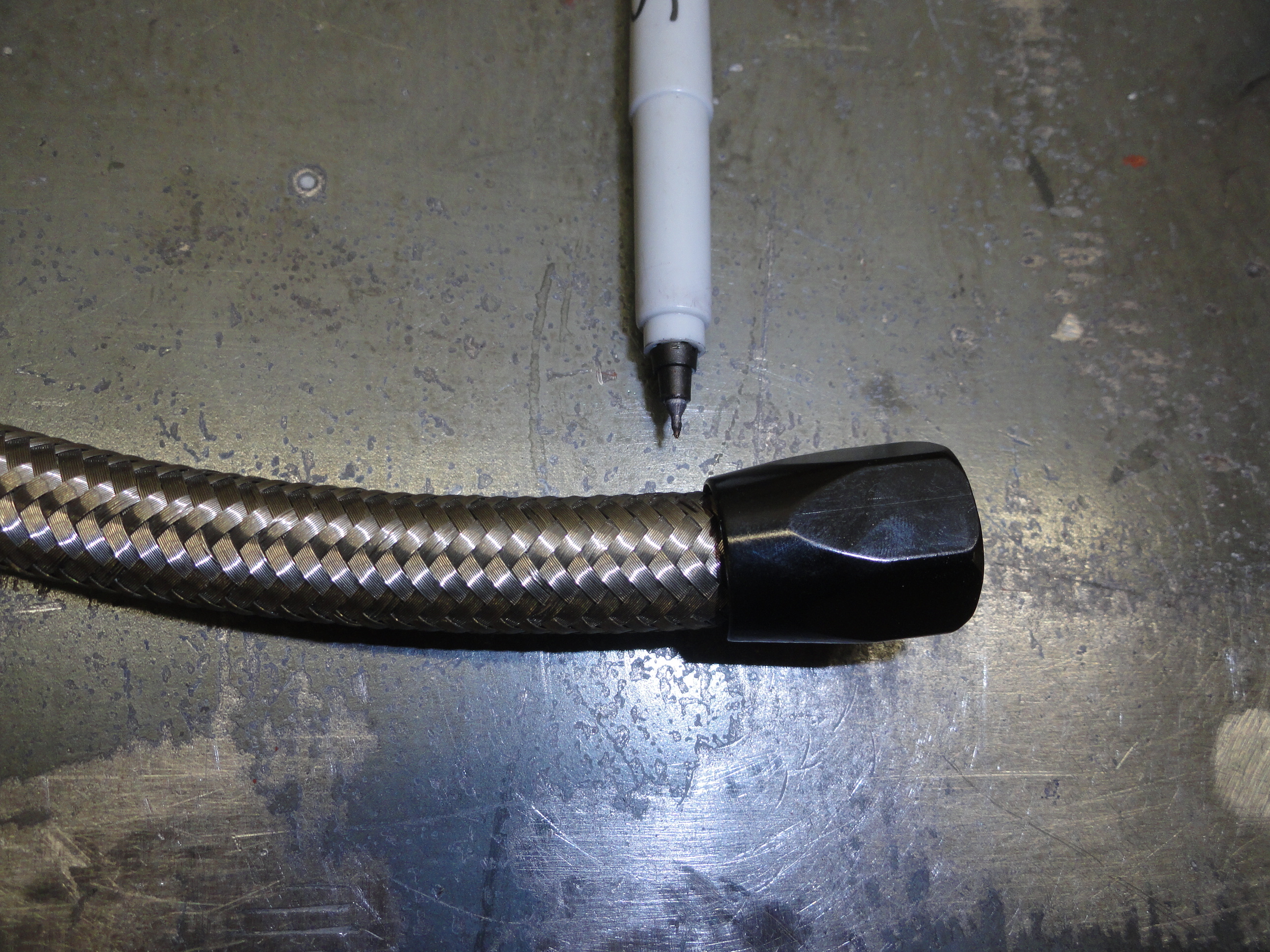
Once you have the connector screwed on all the way, so you can see the rubber is right up against the threads from the inside, make a mark at the end of the connector as shown, then screw the other part of the connector into the hose assembly. The reason you are doing that is so that you know the hose did not back out when you screwed the connector together. That is a VERY secure connection! AN connectors are used heavily in automotive applications today because they do not leak and are easily removed. I think the Stainless braiding gives it a nice finished appearance and I didn't have to invest in any special tools or even have special hydraulic lines made for this purpose. You have to realize that the path of your oil has dramatically changed in doing the full flow modification. Oil comes directly from the pickup in the bottom of the oil pan, through the oil pump and directly out of the block into the filter. After it exits the filter the oil then gets to do its job on vital engine parts and the flow is the same. Those outside oil lines are crucial, so no skimping on quality here!
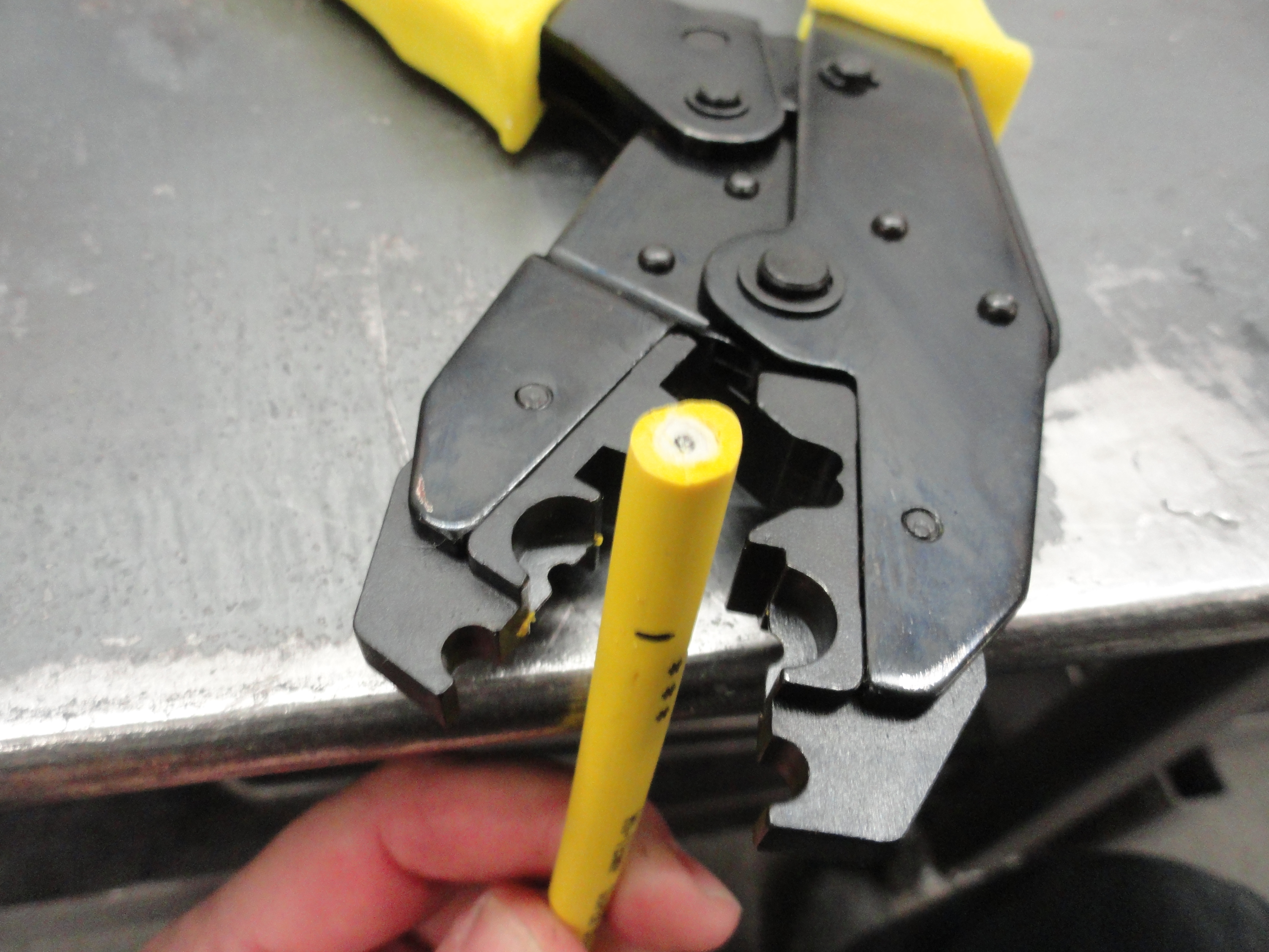
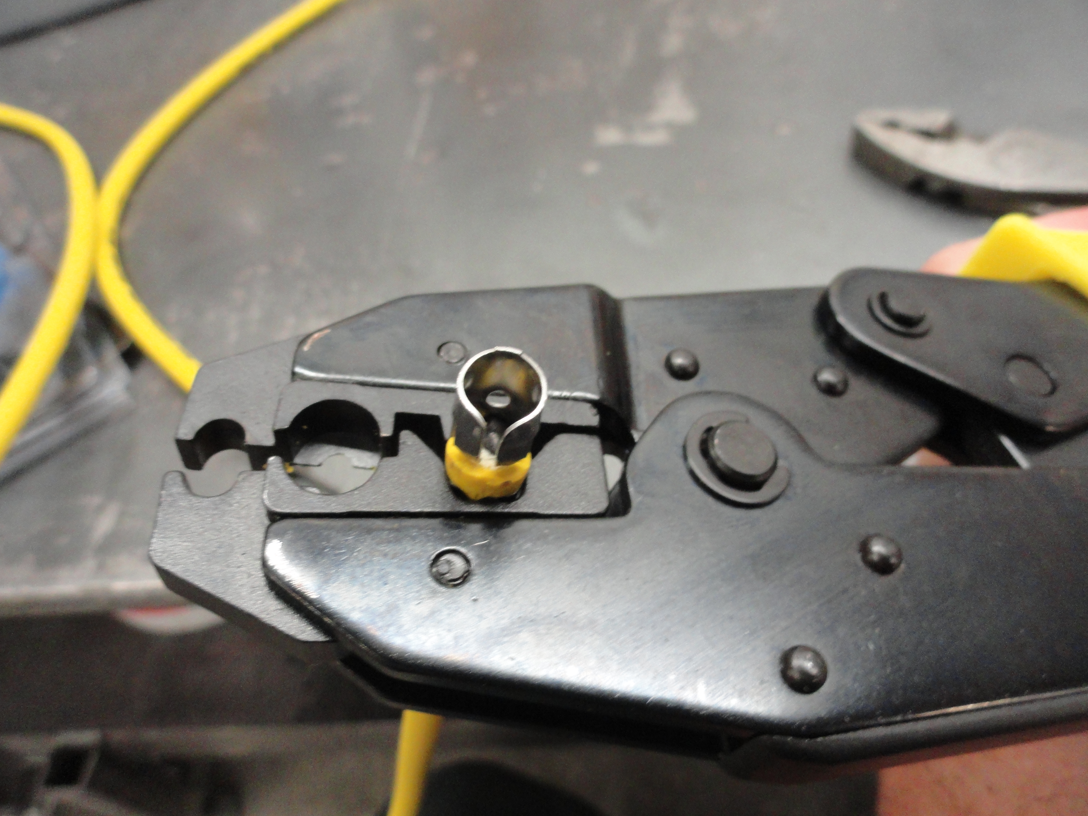
The plugs I chose for this project are new AC-Delco R45 plugs. I gapped them to the spec of .035. Be sure to use the washer that comes with it, and tighten them to 25 foot pounds which is also the spec. For the plugs, I ordered an Accel kit so that I could shorten them myself. I can get a little less than 2 ohms per wire if I shorten them the way I like. These kits are fine and all, but they require a special tool that I didn't have. The crimper/cutter tool I decided on is also an Accel branded tool. It not only comes with the plug wire dies, but also crimp on wire connector dies in two different types. It works very well. I never really understood the need for plug wire kits where you had to put the ends on by yourself. All these years I have just purchased plug wires already made! Go figure! These wires are suitable for both stock ignition systems and HEI.
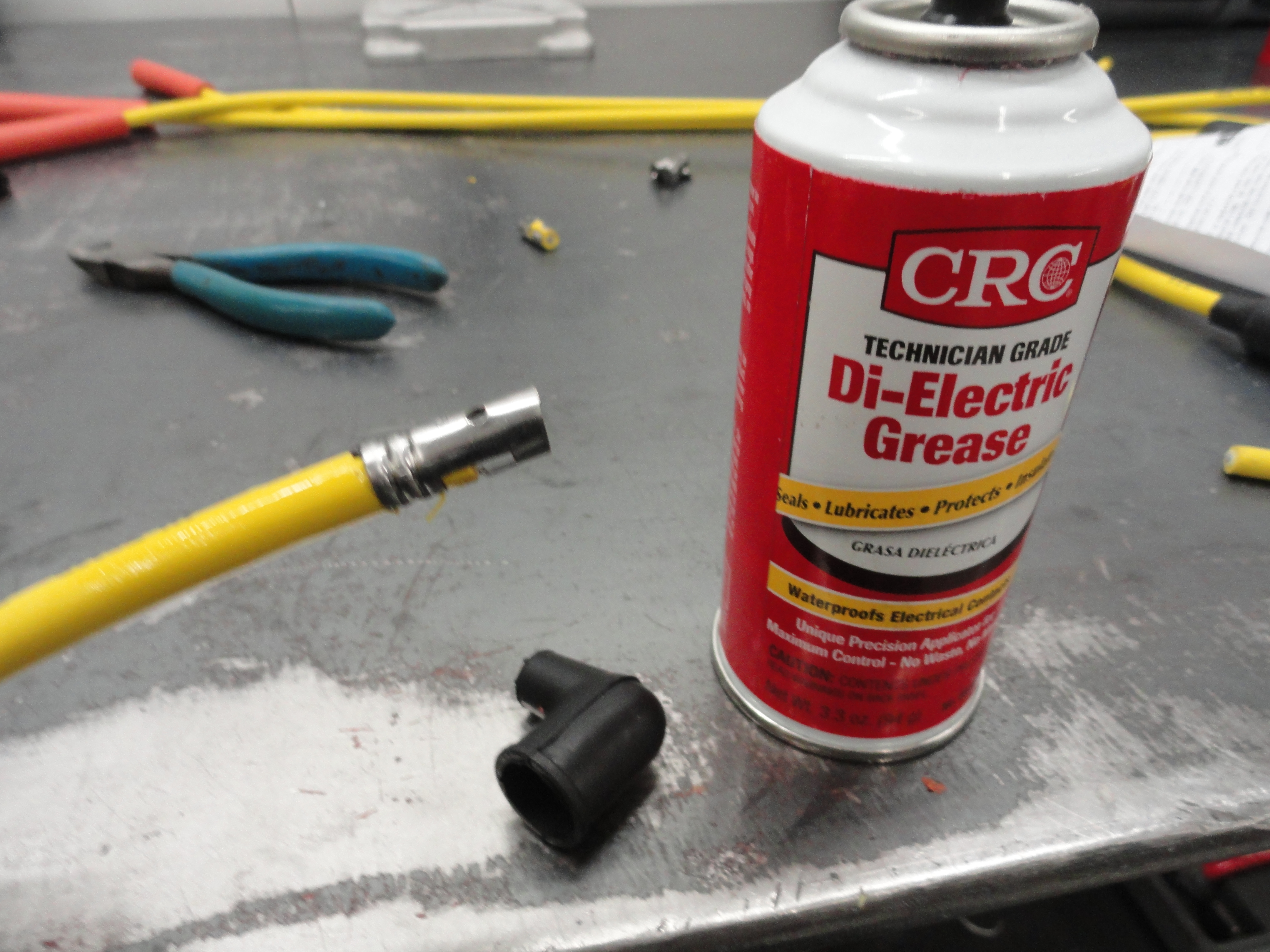

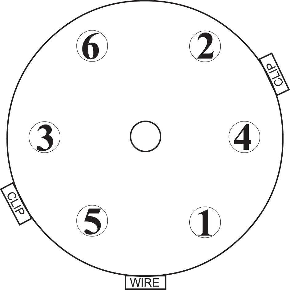
It is important that you do not nick the center conductor while stripping, so the tool really helps. Put the boot on first! Use Die-Electric Grease to get the boot on. It will allow you to slide the boot up and down as needed. Cut 5/8" off the end to expose that much of the center conductor, then fit the metal end on per the instruction sheet leaving 1/16" gap between the top and bottom of the barrel. You may have to tweak the metal barrel so that it goes into the crimper properly, but just take it slow and if you don't get in a hurry, it will all come out great! My only problem with them is they are awfully yellow! Once you have them all made, take an ohmmeter and measure the less than 2 ohms each or so. The longer, the higher ohm value but they should each measure very close to the same. Short ones were 1.80 ohms, long ones were 1.94 ohms. It's just good to test each one so you are not surprised when one of your cylinders isn't getting spark. So how do those plug wires go on again?
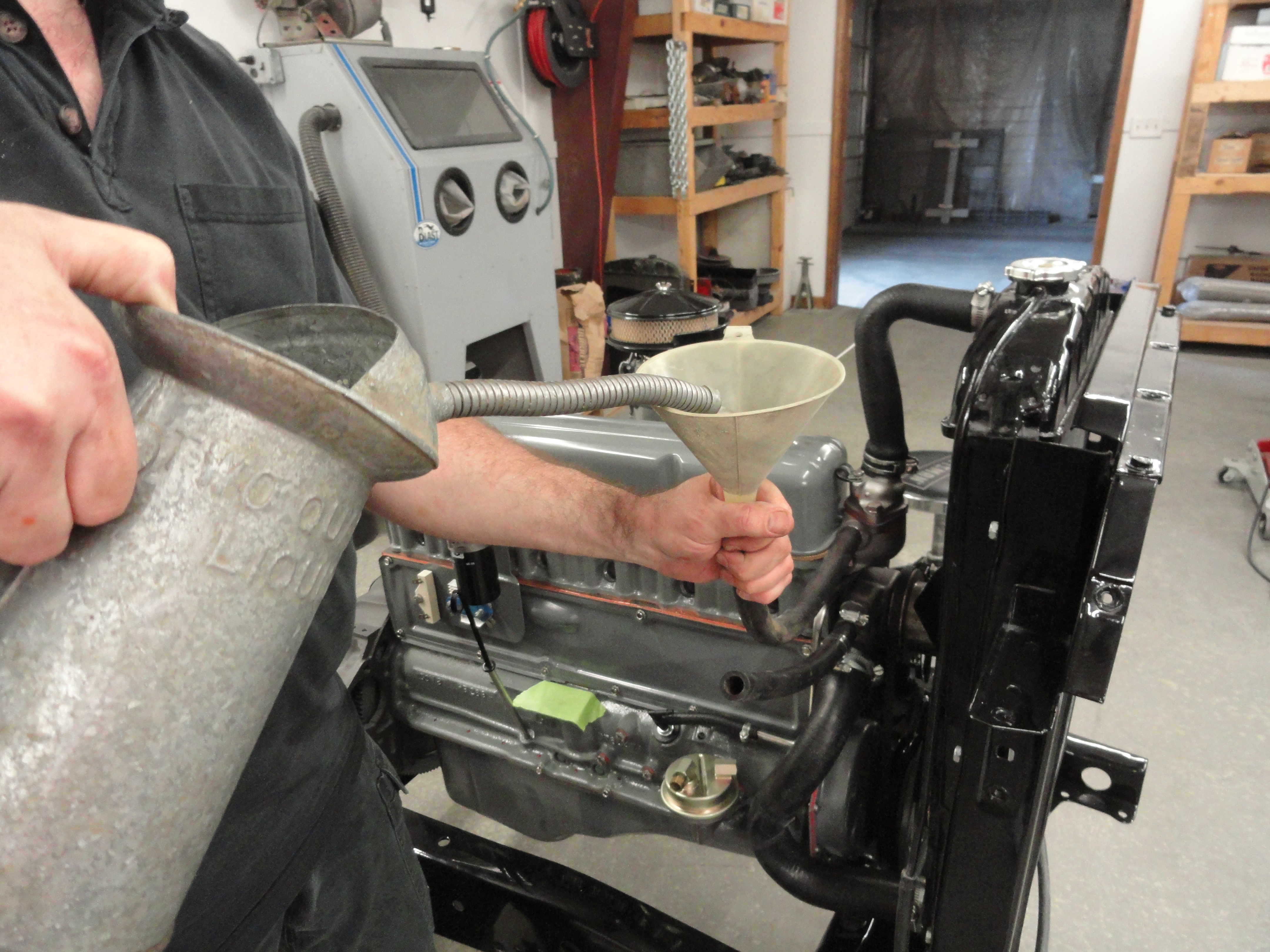
Once you have a nice, neat line setup, we can move on to filling the engine with fluids. No, I have not done this yet! It's one of the last things on the list. So, start with WATER. The time to check to see if you have water leaks anywhere in your system is before you put the oil in. Two places that give you the ability to bypass the thermostat and get water in the engine are the water temp sensor at the top of the head, or the heater inlet to the water pump. I can get to things easier just using the water pump connection, but whatever you choose, open the drain-cock on the driver's side back of the block, and proceed to fill your engine with water. No anti-freeze yet. Once you have about 2 quarts of water in there, your drain-cock should start pouring water all over the floor. Use a pan! The reason it is important for you to open the drain-cock is, the last two engines I have gotten back from two separate machine shops, put a plug in the drain-cock hole and BOTH were blocked and no water would come out. If you have this problem, use .040 gauge safety wire and twist it, then start rooting around through that hole. Eventually (took me an hour this time) the water will flow and alot of black crud will come out. This after I was very specific that I wanted the block cleaned because of that. To be fair, the machine shop works on all kinds of engines and doesn't necessarily understand a single anomaly associated with a Chevy 235 engine. Be sure to repeat yourself and even then, have some safety wire handy.
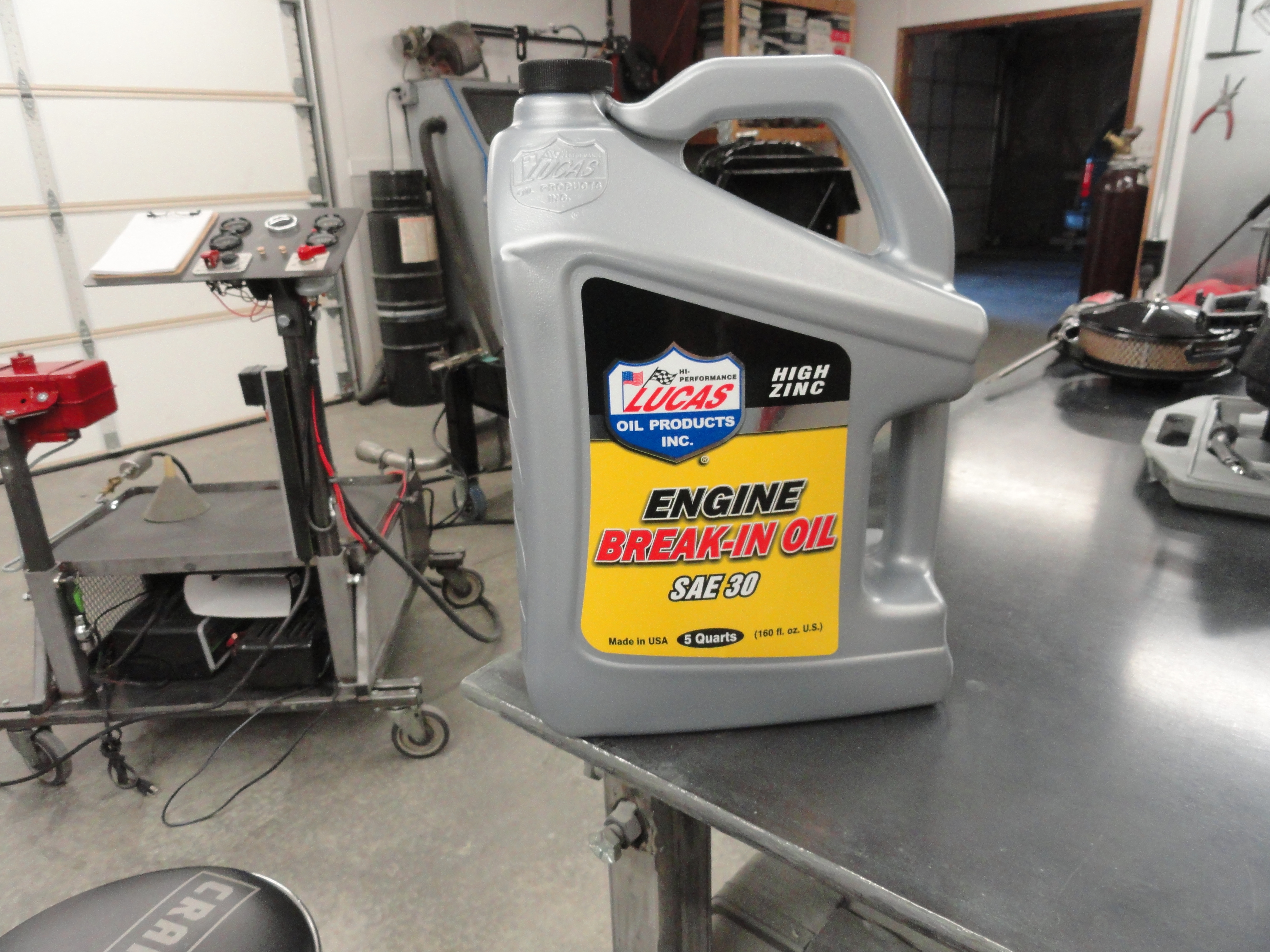
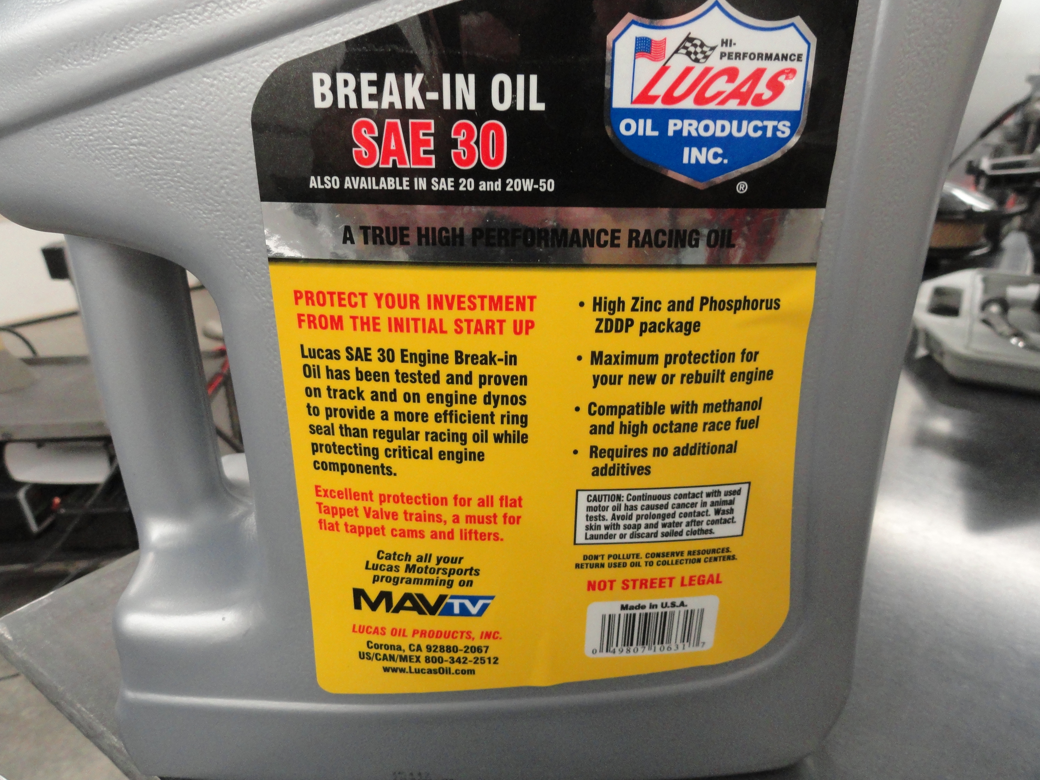
The very good reason we are putting water in the engine first is so that we can assure ourselves there will be no water in our oil, no leaking on the floor from anywhere, etc. Once its full, wait till the next day and pull the oil pan plug, inspect the floor for water, etc. You should be good to go. If not, address whatever is happening. If the water jackets are holding, now on first run-up there is water in your engine. If you want to go back and put anti-freeze in, use the drain-cock on the back of the engine for draining!
Put your break-in oil in the oil filter, then fill to the dipstick full level. Check for leaks, or anything that could mess up a full engine run. We want to do whatever preventative maintenance is required before the initial run-up. When I put the oil in, I like to pour it over the entire valve and rocker assembly so I do this with the valve cover off. You will need it off for the next procedure anyway. Whatever you do, with a full flow oil system such as this one, you want to make sure your hoses are all connected properly and you are ready for this step. You need 6 quarts of oil for this configuration. One in the filter, 5 in the engine.
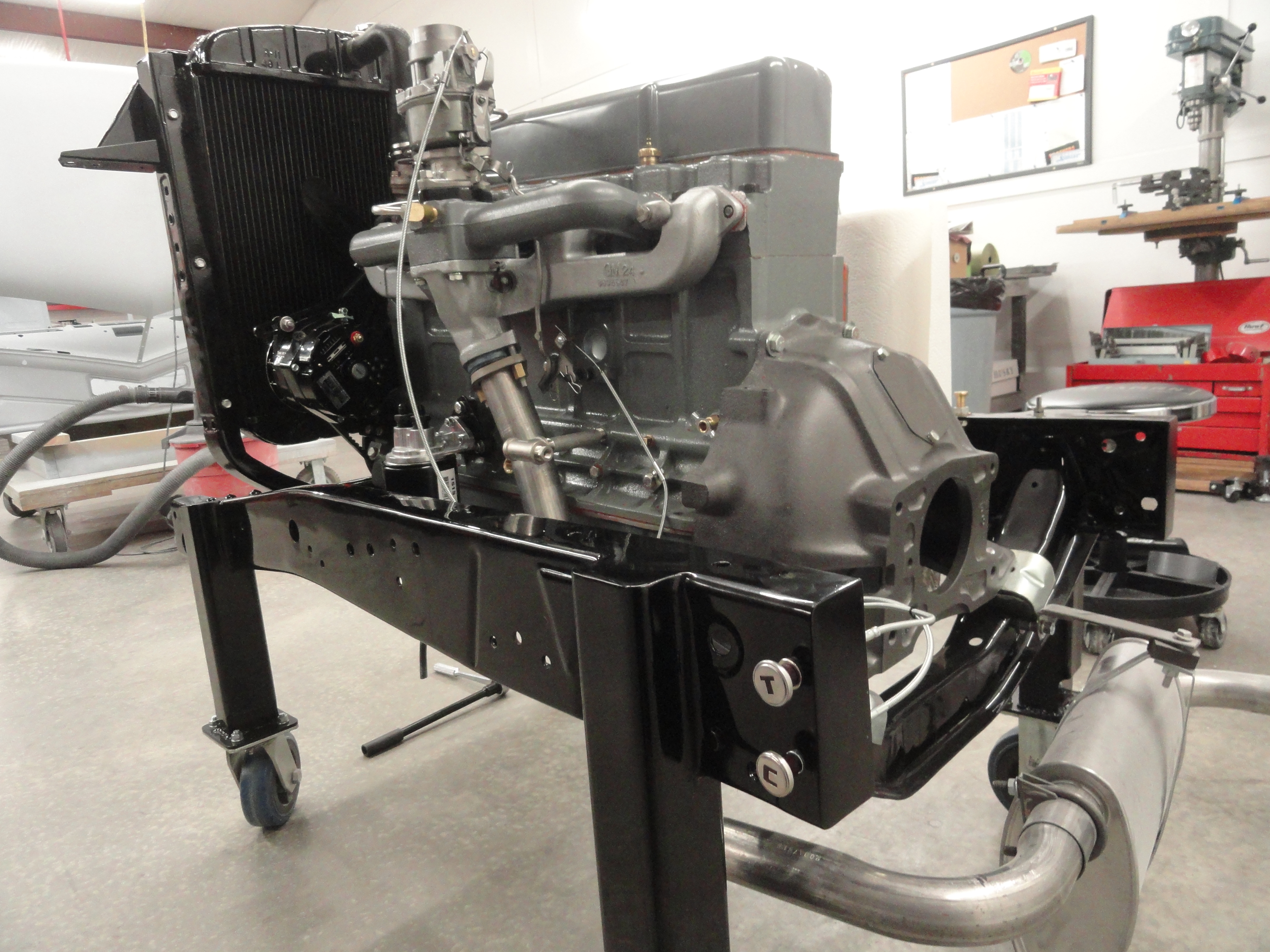
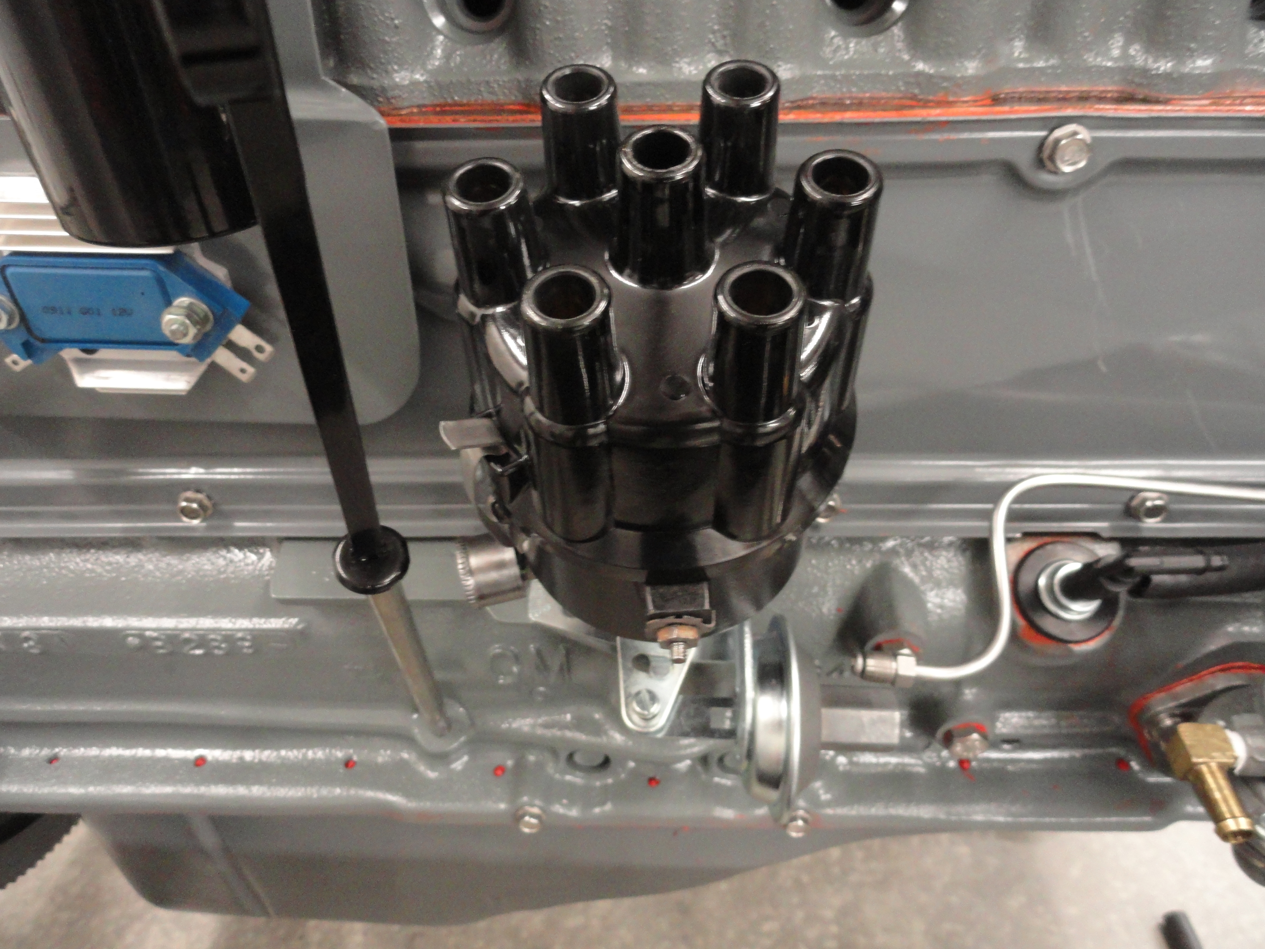
I am going to do the initial run-up with Lucas SAE 30 Break-in Oil. Brad Penn is known to be good for this too. They meet all the break-in requirements. They have extra Zinc and other Additives in them to help with seating the rings, cams, lifters, etc. I like to pre-fill the oil filter, then put enough in to show good on the dipstick. I will check the oil alot throughout this process and add more when needed. Of course before initial run-up, make sure the valves are adjusted (engine off) cold so they are in the ballpark. Also run the oil pump using a screwdriver minus the handle in your electric drill to get all of the oil flowing where needed. The very last place oil is sent is the rocker assembly so if you have oil at all the rockers, you can be sure oil flow is good throughout the system. Ensure your distributor is put in so that it is in #1 firing position. I prefer the 5 o'clock position on the distributor with the distributor wire connection facing directly away from the block.
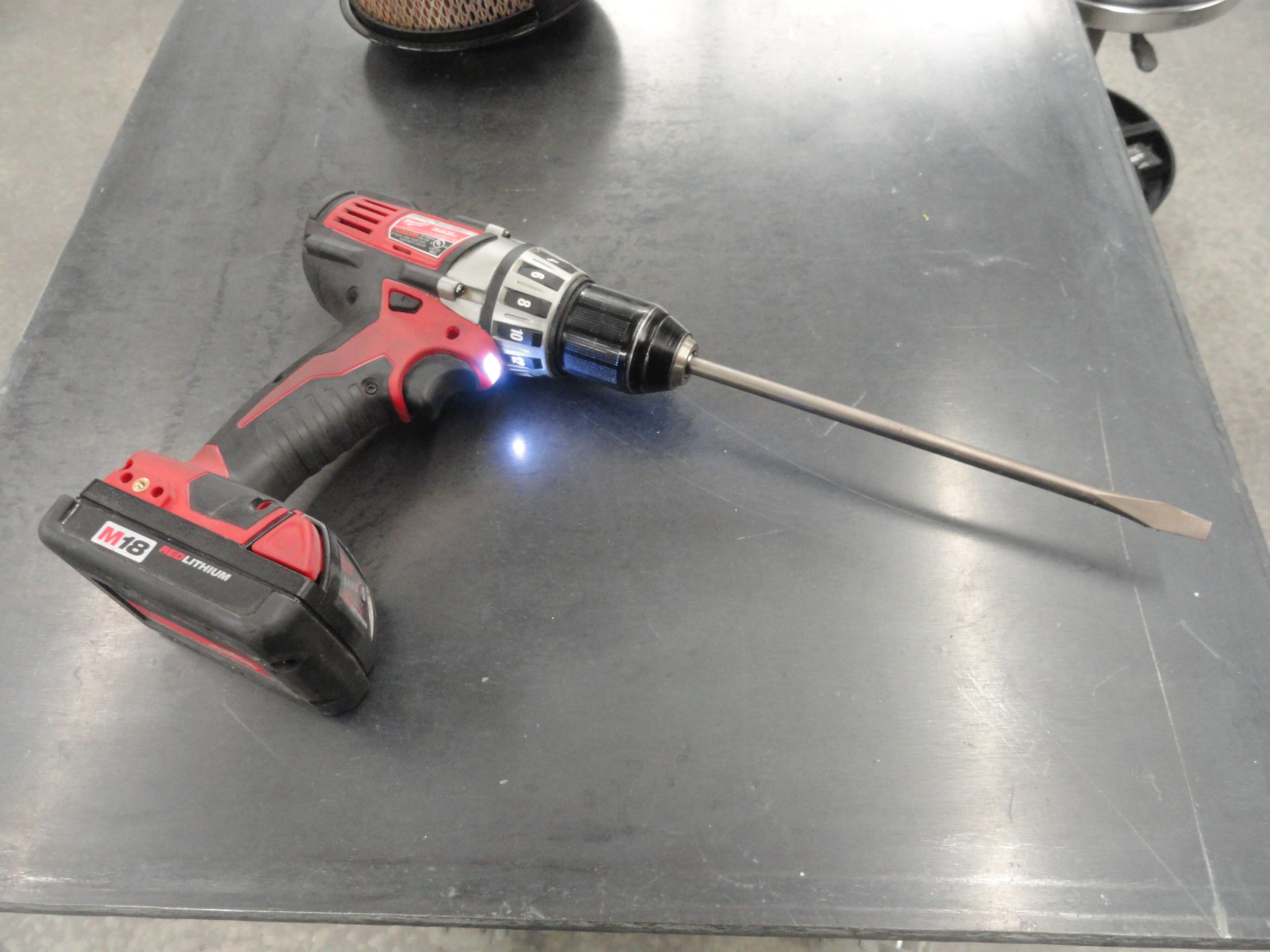
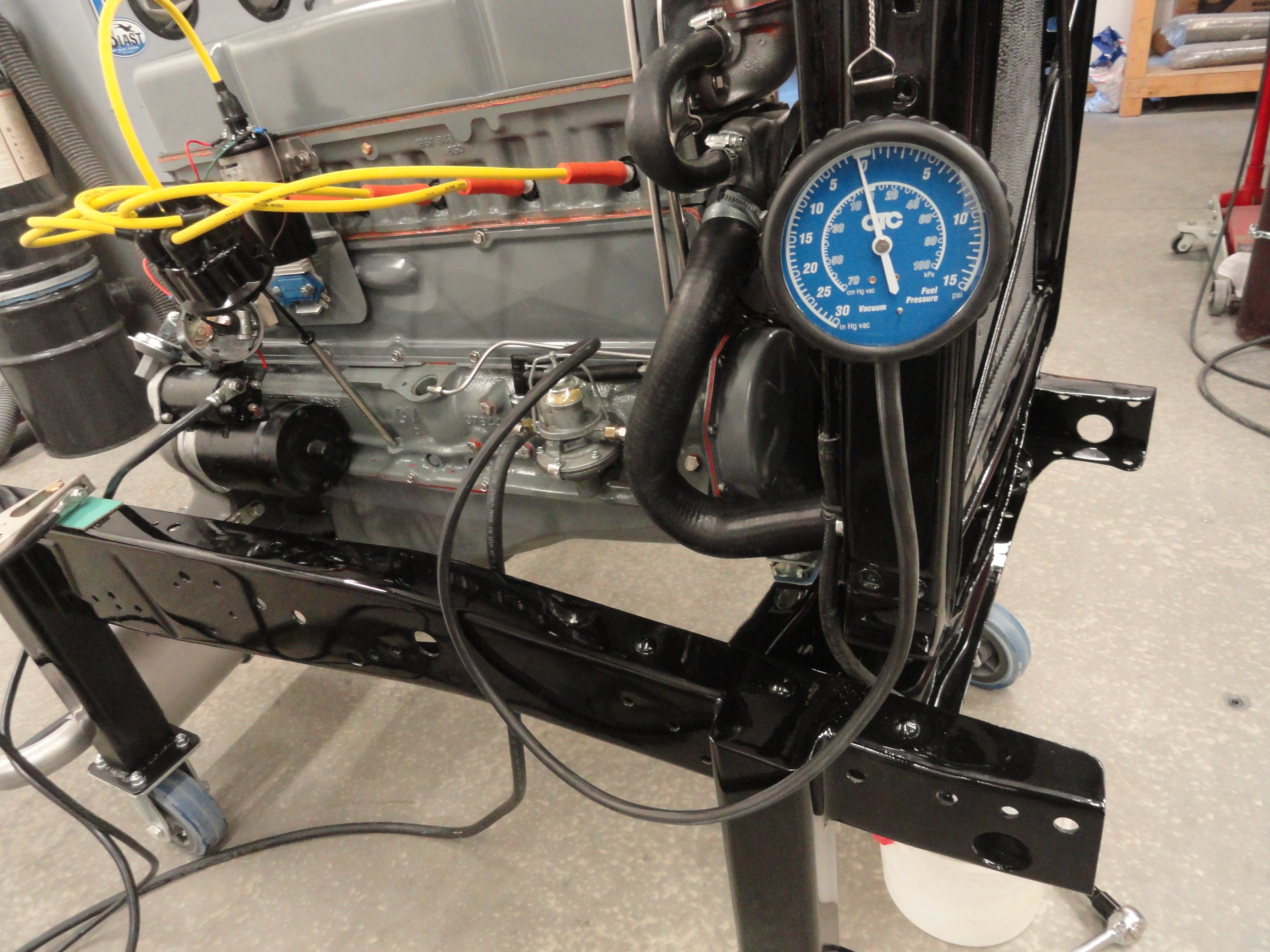
You put the distributor in with the rotor facing at about 6 o'clock because the cam gear is going to move it back. This being the case, you want to set your oil pump drive at the bottom with a screwdriver so this is allowed to happen. Remember, with the valves of #6 rocking, #1 is in firing position thus where you put your Distributor in. Prior to starting it up, we will want to set up some test equipment. One of these is a Vacuum Gauge. This is a very quick way to get your timing in the ballpark and when you are shooting for a flawless 20 minute run, this will help stabilize the engine as soon as possible. The procedure is to hook the Vacuum Gauge to the intake manifold. I AM doing this! The PCV valve has a second unused port on it so I am initially plugging the PCV valve so essentially its the very same thing as going direct to the intake.
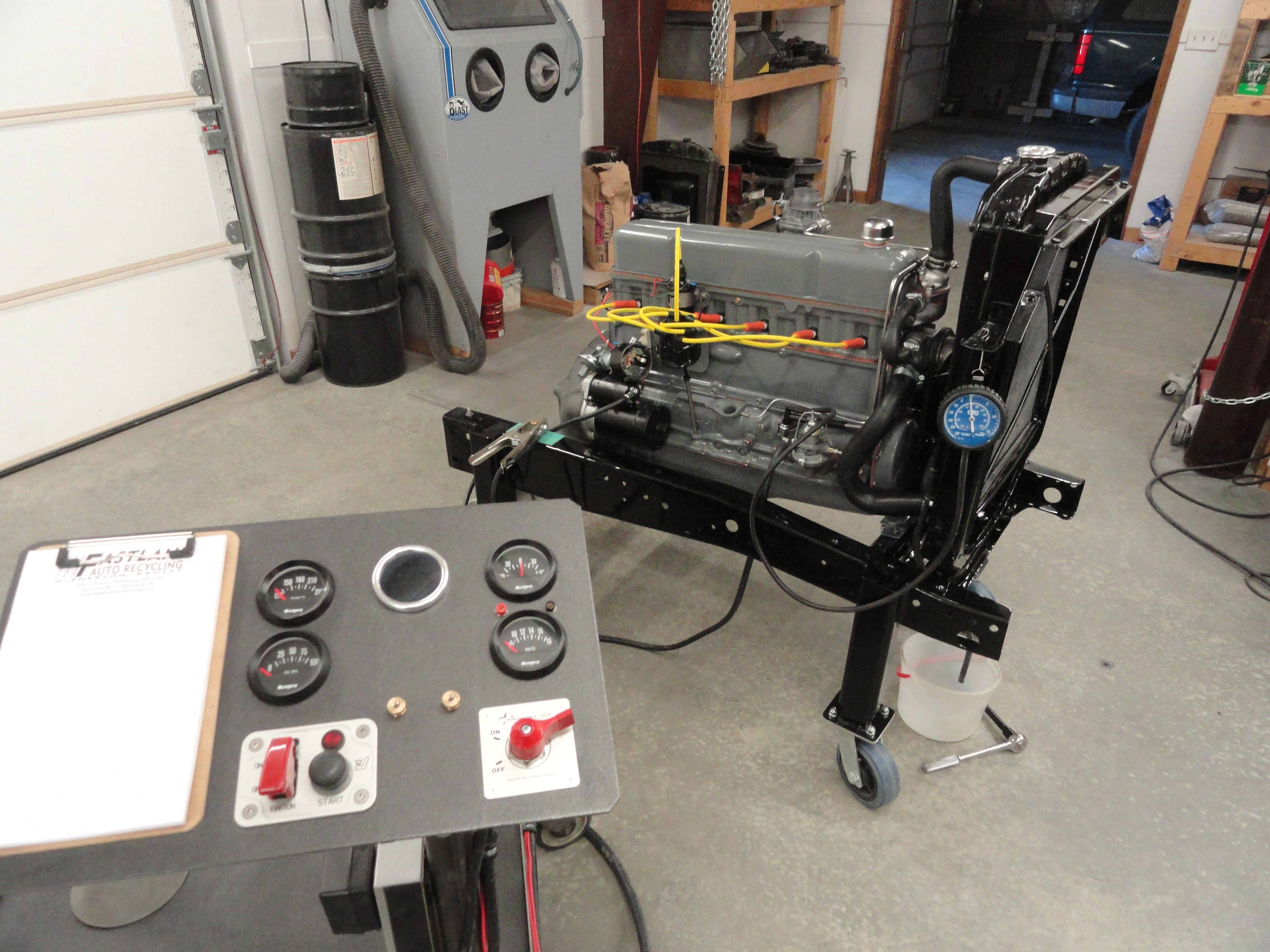
We are getting close to firing it up. A very exciting as well as apprehensive time! You want to really think things through and a friend of mine came up
with a nice Pre-Flight Checklist: (thanks Joe!)
In the case of this particular initial break-in runup, there were a few things that I did wrong. So in the interest of helping you do it right, here is the list of things I could have done better:
The Break-in Run was 20 minutes at 2000 RPM with the last 5 minutes slowly raised to 2250 RPM. Everything aside, it went rather well and I did not have to do anything during the run except keep an eye on things. In the end, the exhaust fumes were clear, no smoke and there was no Blow-By apparent at the valve cover cap. The spark plugs had a little soot on them which I attribute to it being a vintage engine with a 'one size fits all' Carb Jet on it. The post Break-In Compression numbers were:
Don't forget to check out: Initial Break-In Runup of a 1959 235 Engine, THE MOVIE on my YouTube Channel here: Deve's DTN YouTube Channel
I like to rebuild my engines as if they would be used in a daily driver. This attitude ensures a quality build that no matter who you sell it to, they will be more than satisfied. A daily driver requires a different thought process NOW than it did 65 years ago. Nowadays we know that slits in the valve cover that expose your engine to all kinds of dust, dirt, crud, etc is a bad idea. If we close those slits and put on a breather style filtered cap, our engine will last longer. If we put a modern PCV valve where the Road Tube used to be, we can evacuate all of the exhaust gases from the bottom end and, our engine will last longer. If we filter 100% of the oil before it ever hits the internal parts, our engine will last longer. These are things we CAN do at the rebuild stage very easily. The cost for all three of these improvements including the machining process is under $150. Why not?
There are ways to cut the cost of this build that make sense. Things like stainless steel engine bolt kits, an 80 amp alternator, etc, etc. When you are done, what matters is that YOU are happy with it. I hope you have enjoyed this adventure and gotten some useful information out of it. If you can think of a better way to say something, or improve this document, don't hesitate to email me at deve@speedprint.com.
I may write what you see, I may even do all the physical labor, but the component that makes this endeavor a guaranteed success is the people who are giving
of their time and knowledge to keep each and every procedure in this document exacting and precise. The way it works is, I ask at least three people the same
question. If all three agree, and it makes common sense, it goes in the document. If two agree, I get a fourth persons perspective, always keeping the odds
well in the favor of precision. This is done at each and every step using Chevy documentation, outside sources, and tapping the expertise of some of our best
engine re-builders from all over the world. Some of these people are notable because of their giving attitude and the fact that they were always just a phone
call away. Dave Folsom is one of them. Dave has built a career servicing these engines and his knowledge, expertise and friendship are invaluable. Check out
Dave's Blog. Tim Lederman keeps me honest where all of the documentation is concerned. If I don't know where to
find some important fact, Tim takes the call. He has a very helpful site HERE! When it comes to machine shops,
I have been very impressed over the years with the expertise of Jim of Jim's Motor Machine in Galva, KS. Jim's shop specializes in these
vintage machines and his endless expertise has been essential to keeping things precise.
Documents like this one would not be possible without the vast amount of support I have received in just getting my questions answered at each step of the
process. I rely on people all over the world. Jeff Diamond who resides in London, England was a great resource as well as the many local mechanics and forum
resources that are out there.
Disclaimer: Myself as well as most of our contributors are retired and give our information freely for the sole purpose of helping others. If you attempt any of this, you must follow accepted safety procedures and clearly understand the dangers of machinery, equipment, etc and how to mitigate the dangers by being cognizant and diligent while operating machinery. Please just use your common sense! And don't forget to have fun!