

Deve's Technical Network
1947-1955 1st Chevy Trucks
216/235/261 Engine Solutions & More
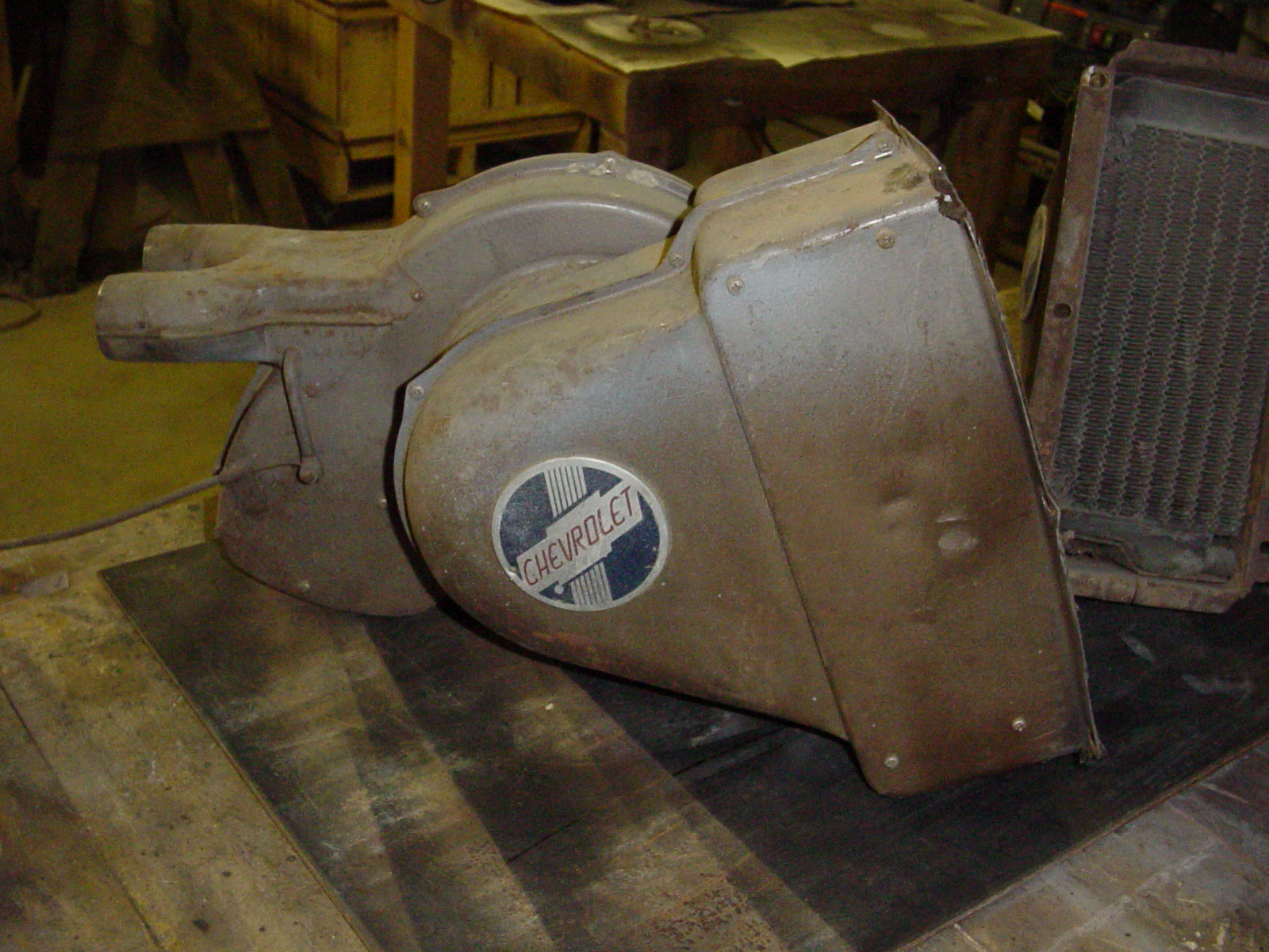
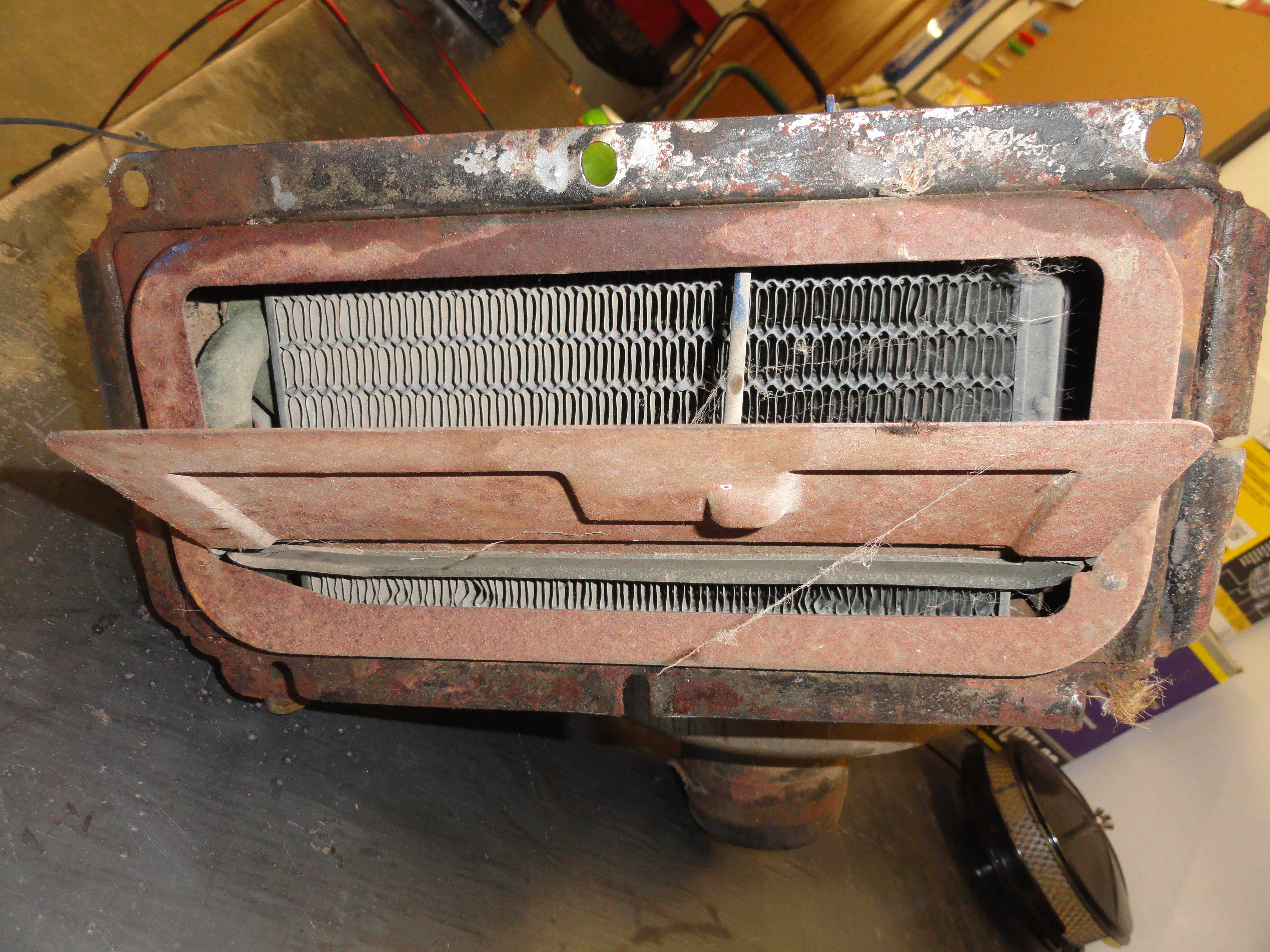
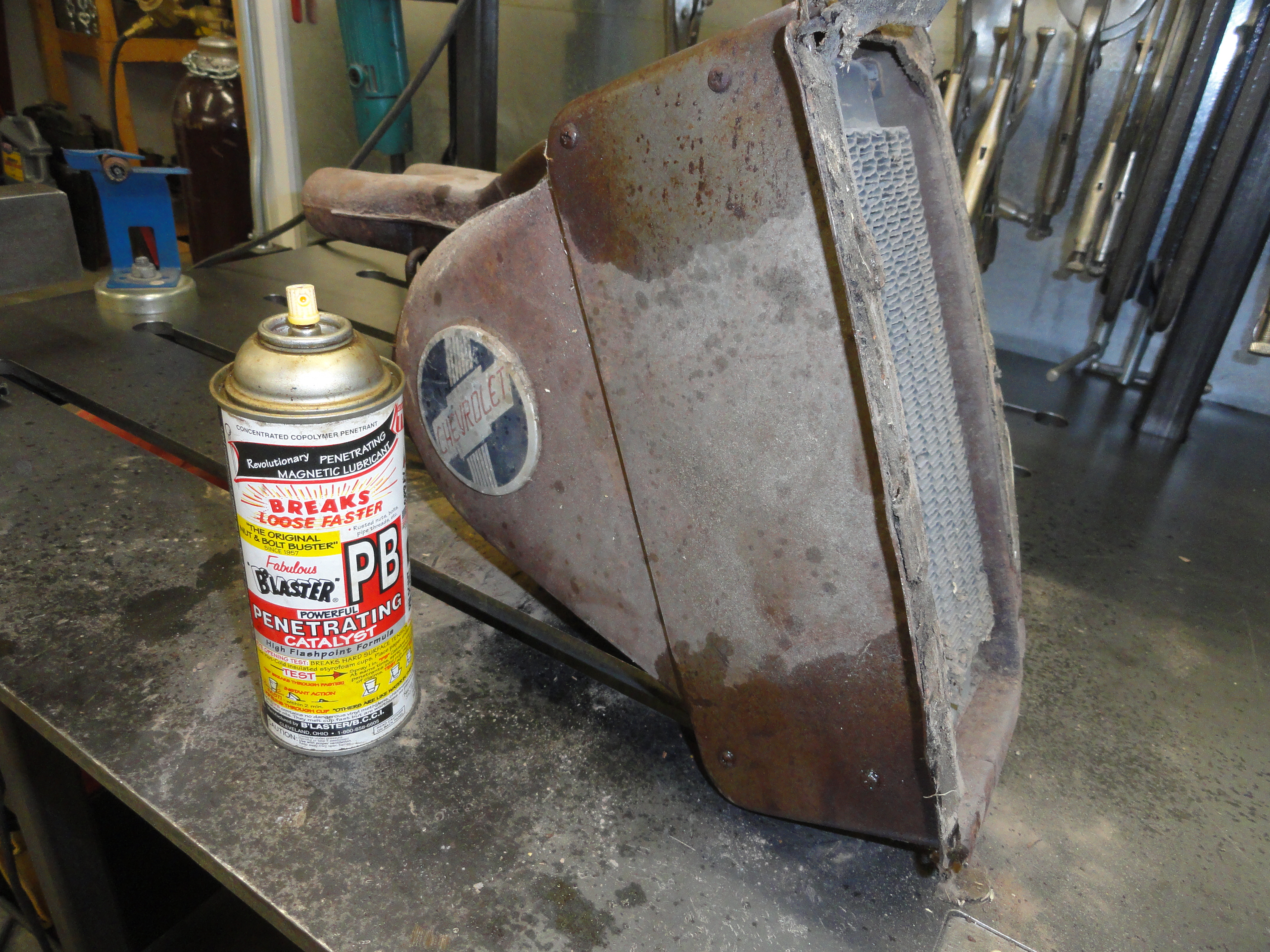
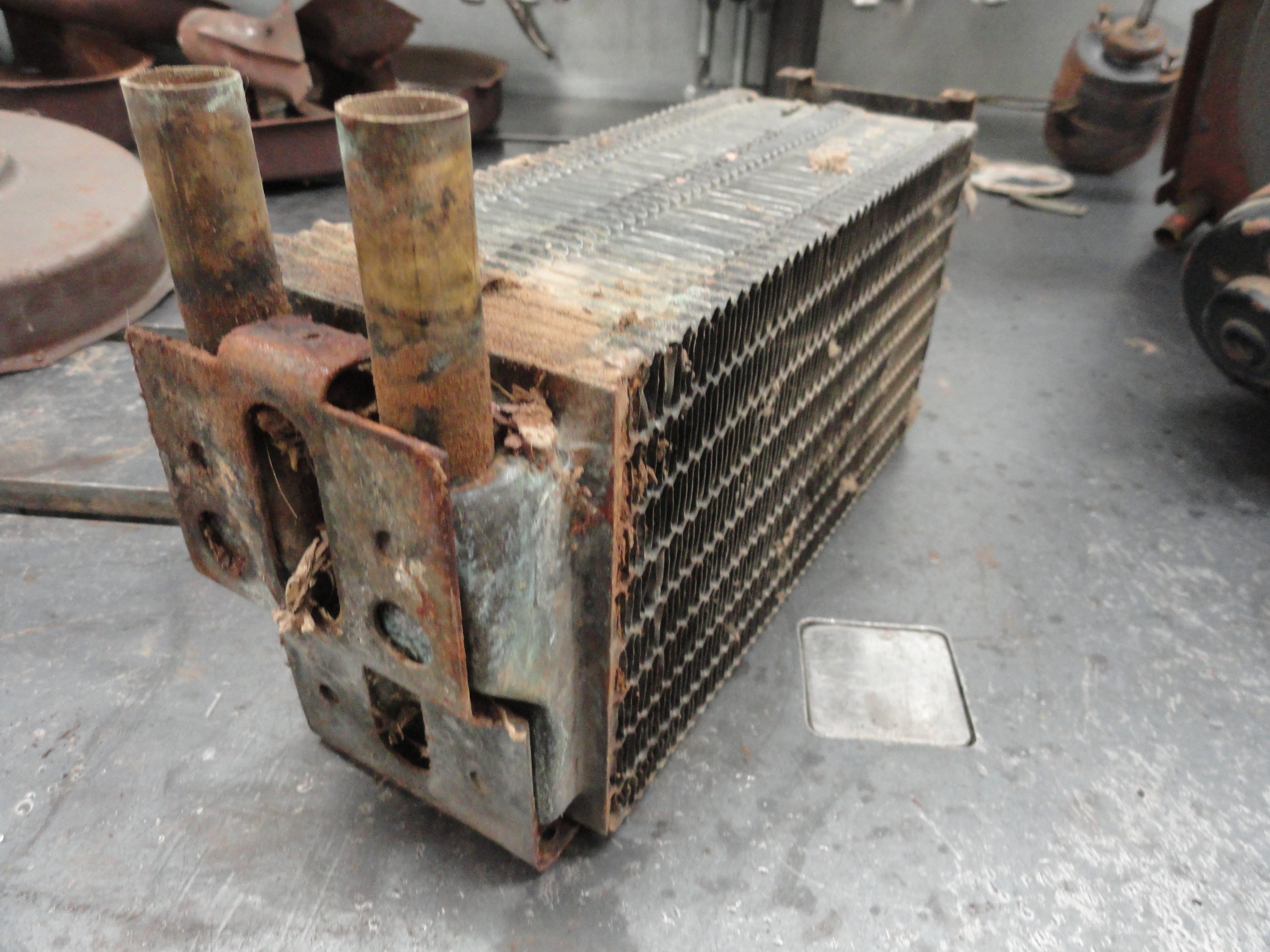
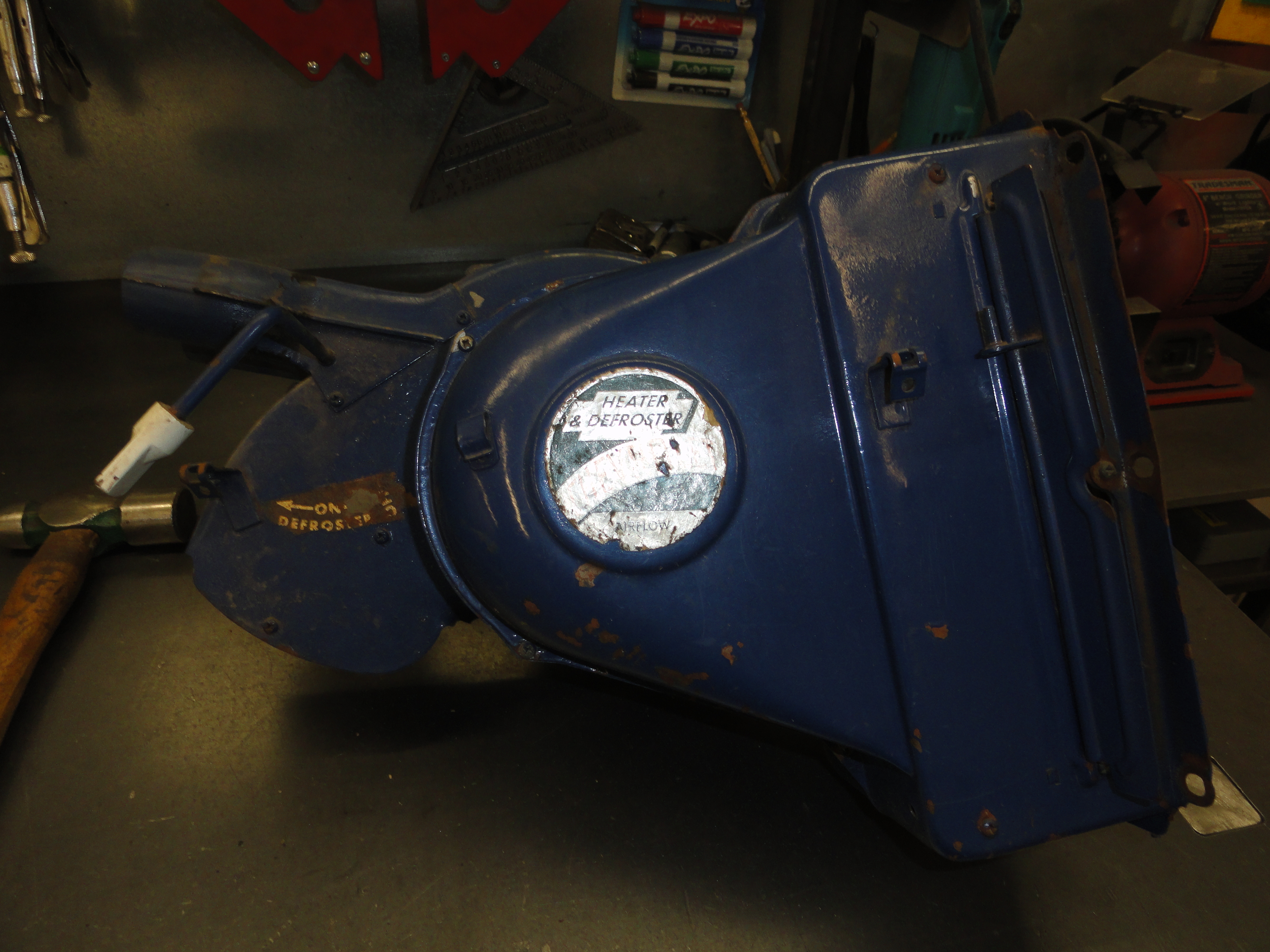
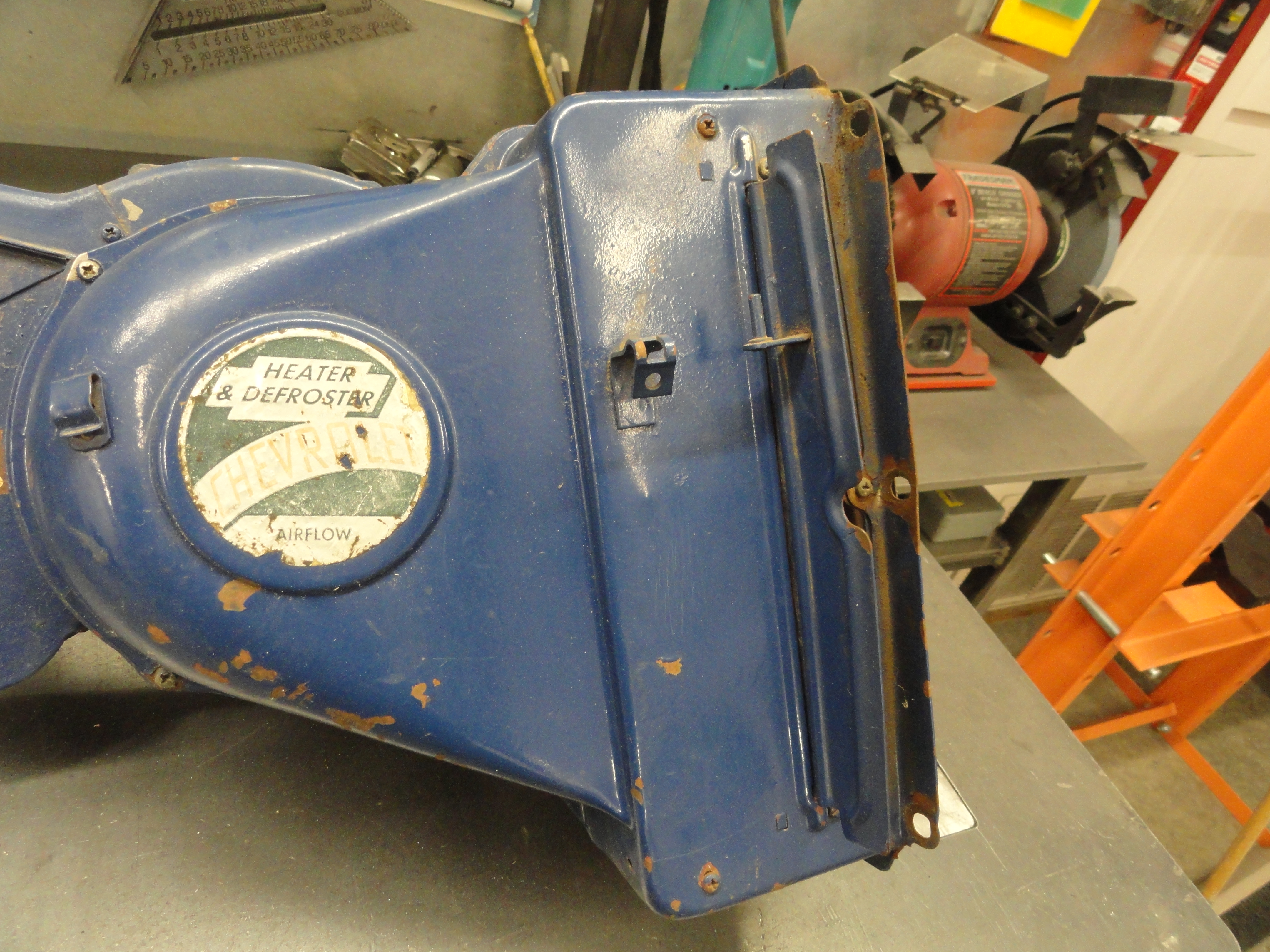
Here is the heater just taken out of the truck. Where to start? We have a few issues to consider. The two main issues are making it look like new and making it work like new. In this case it will be better than new since we will also use a 12 volt motor to run it. In addition, the unit must look 100% original.
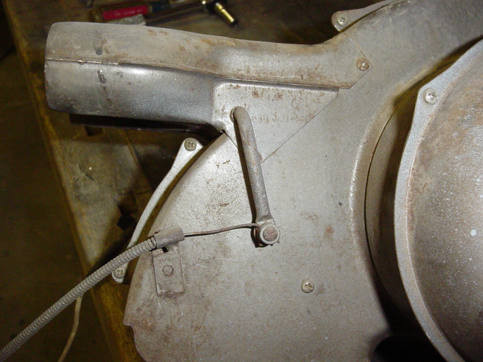

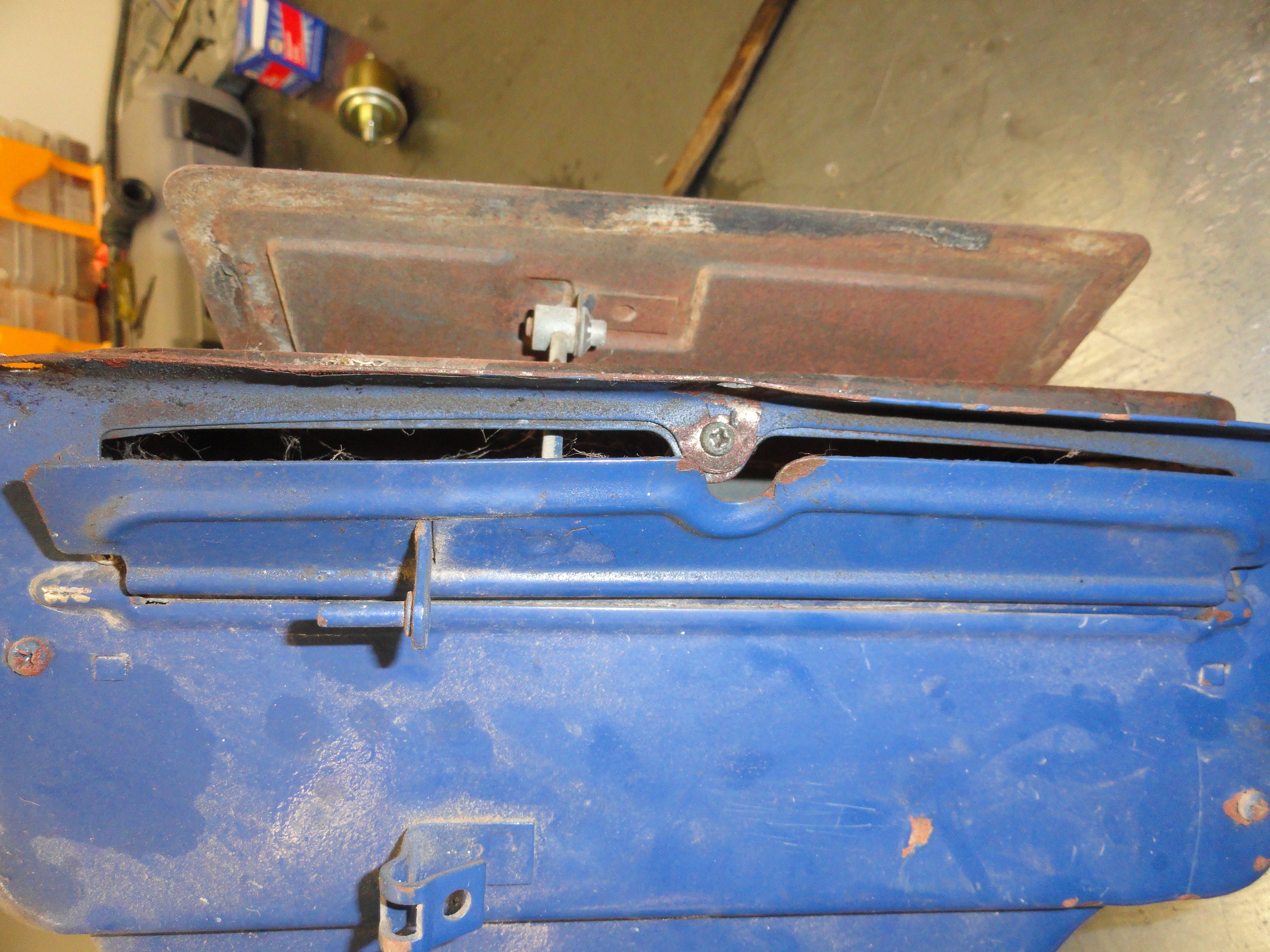
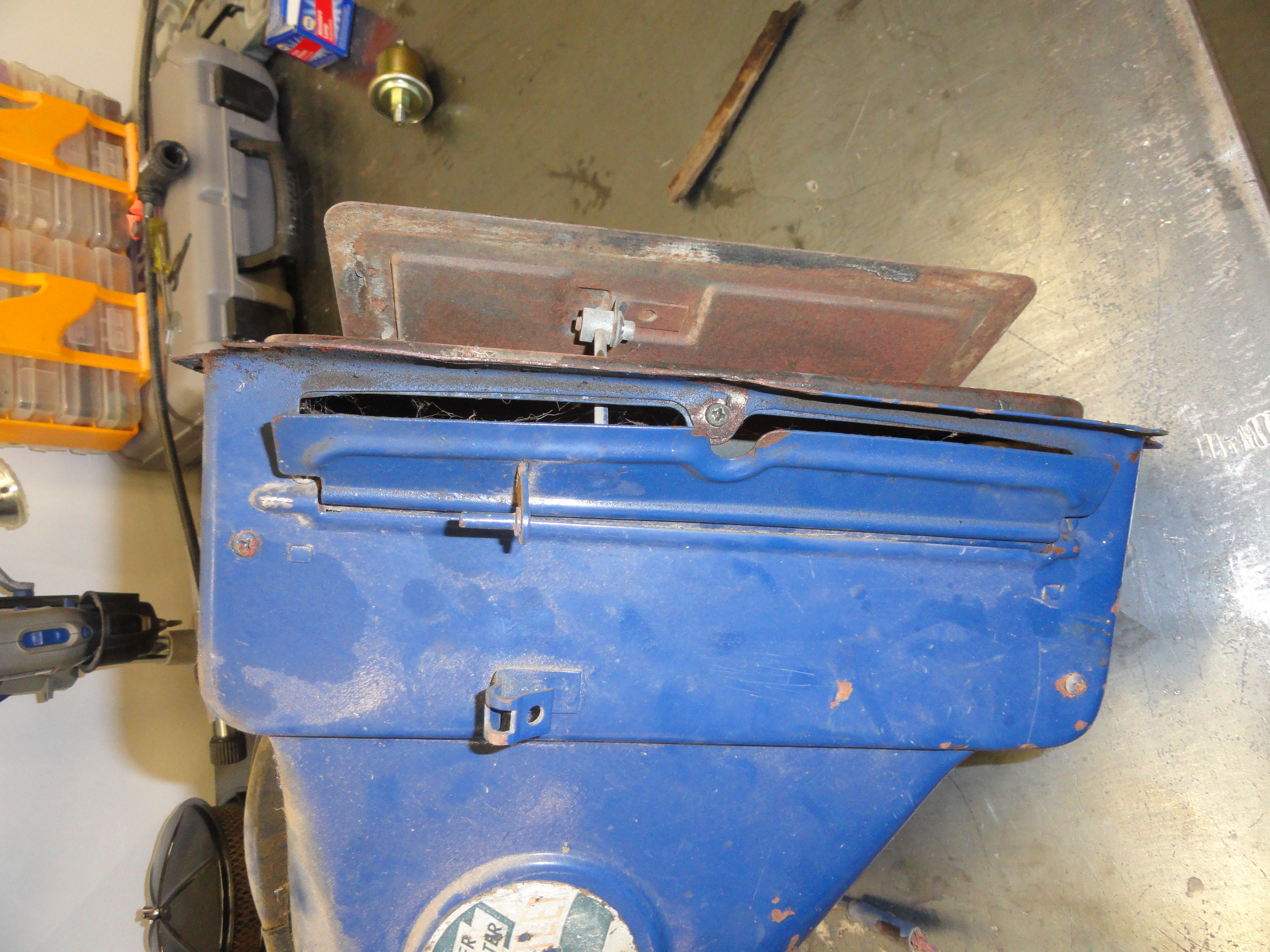
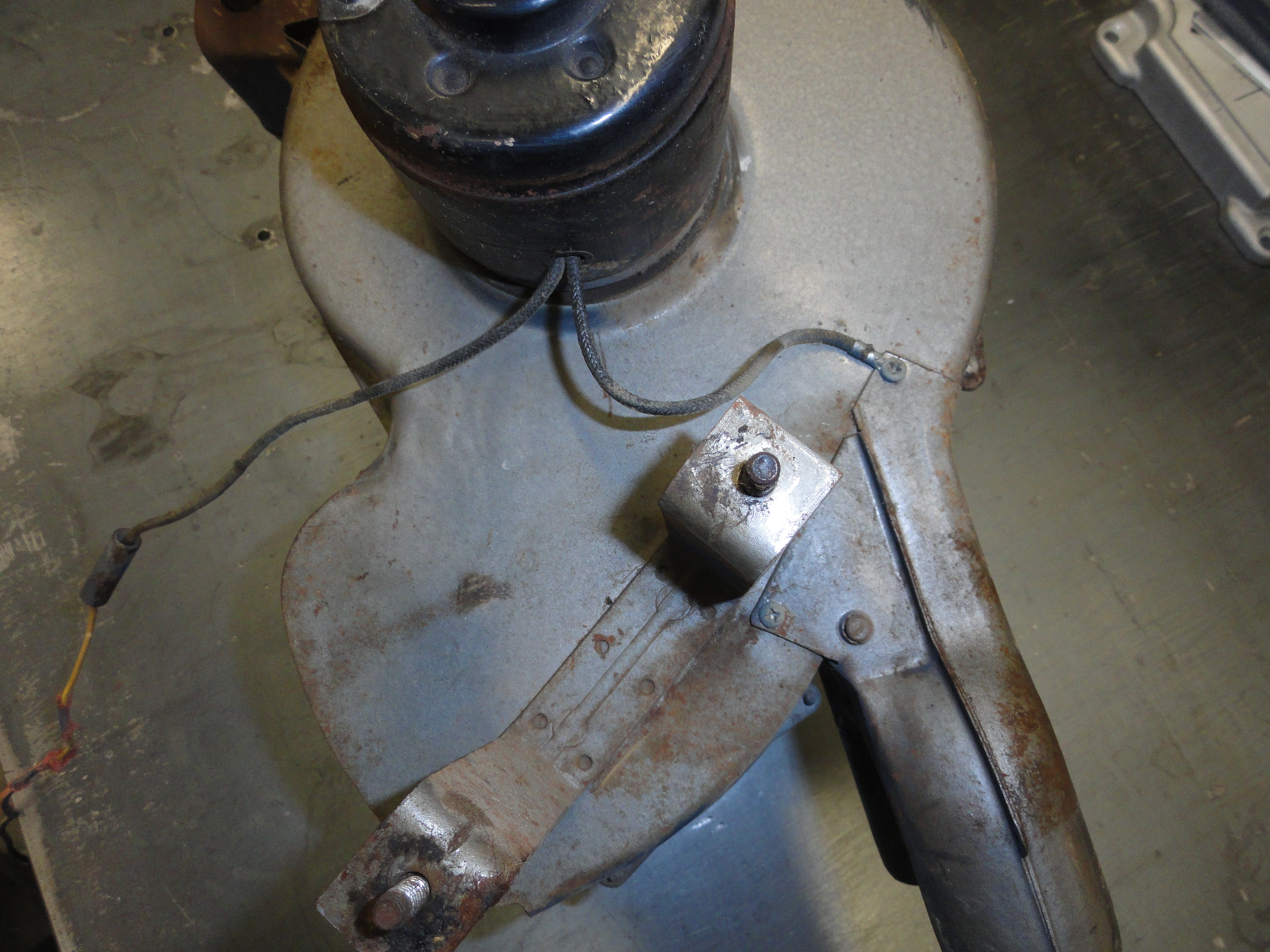
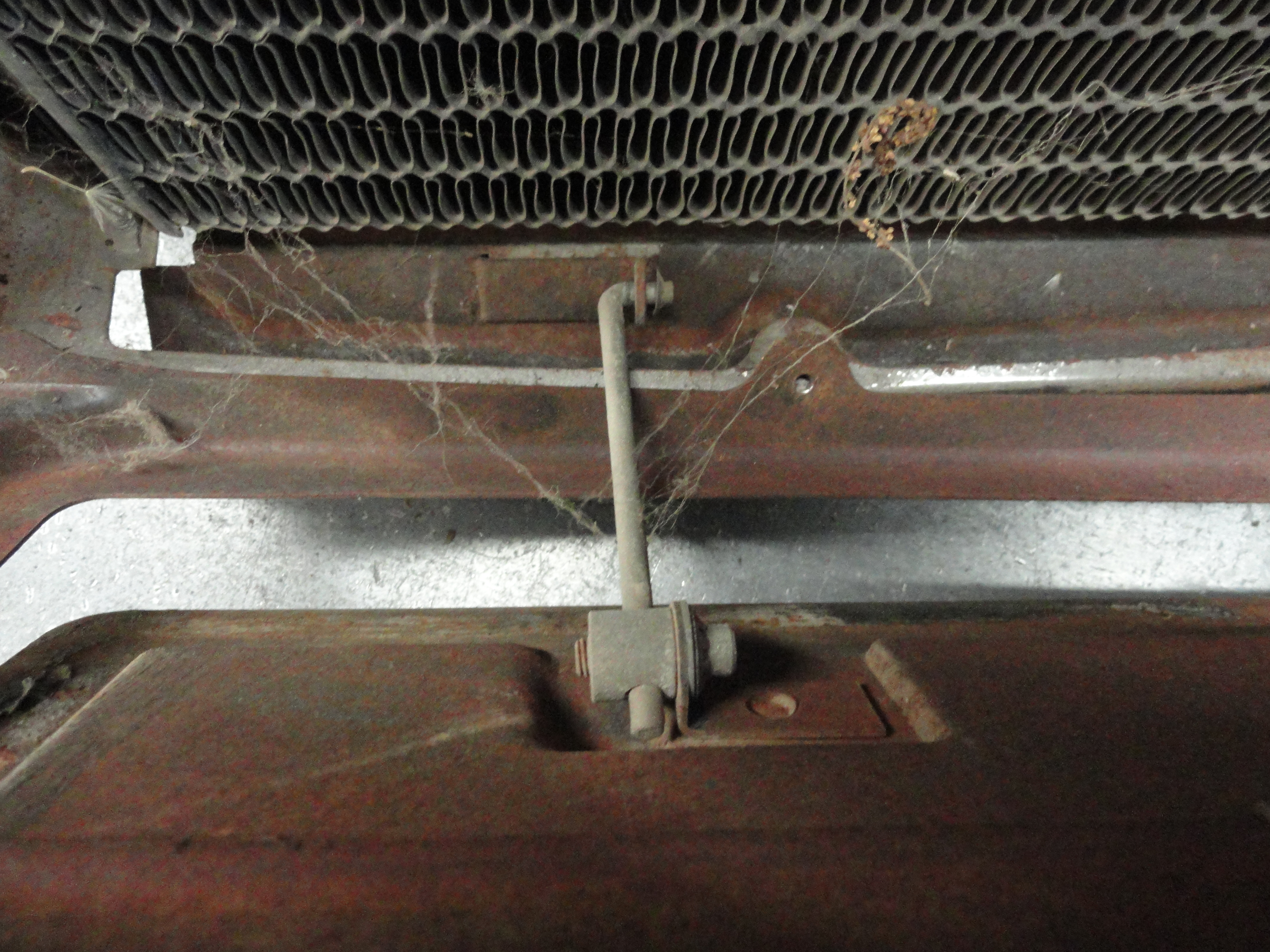
Let's get a few shots of the heater still fully assembled so that we don't forget how it goes back together. This picture shows not only how the ducts are arranged, but how much play in the defroster cable is normal. This will help during re-assembly. The picture on the right shows where the negative lead of the motor is grounded to.
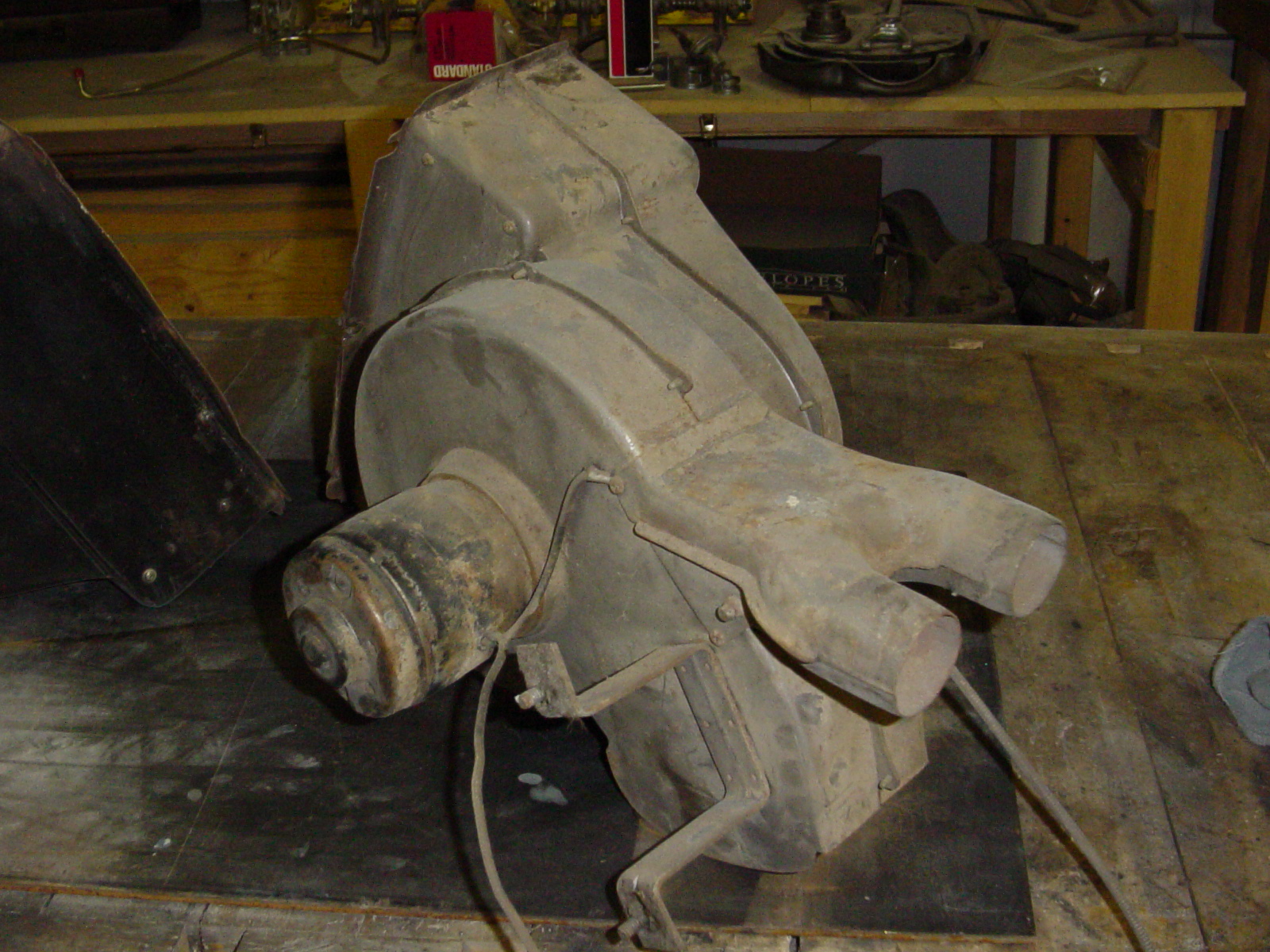
This one will help us figure out the relationship of the parts during re-assembly. Once you have it apart, it becomes apparent how important the before pictures can be. Since this article was published, I have done many more of these so I decided to add more pictures and content.
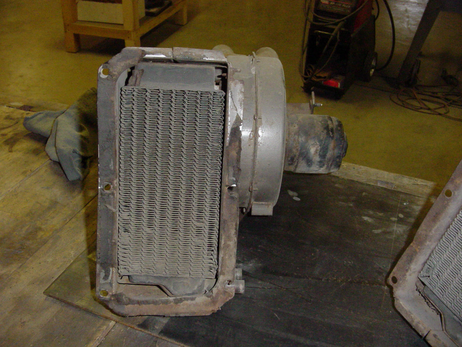
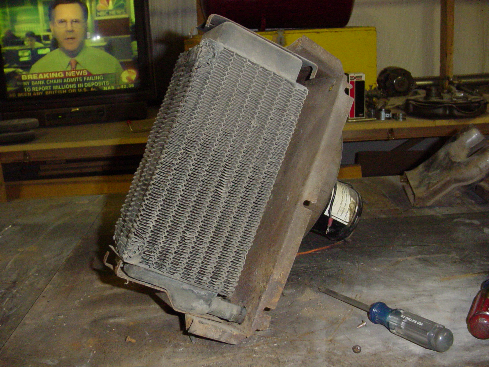
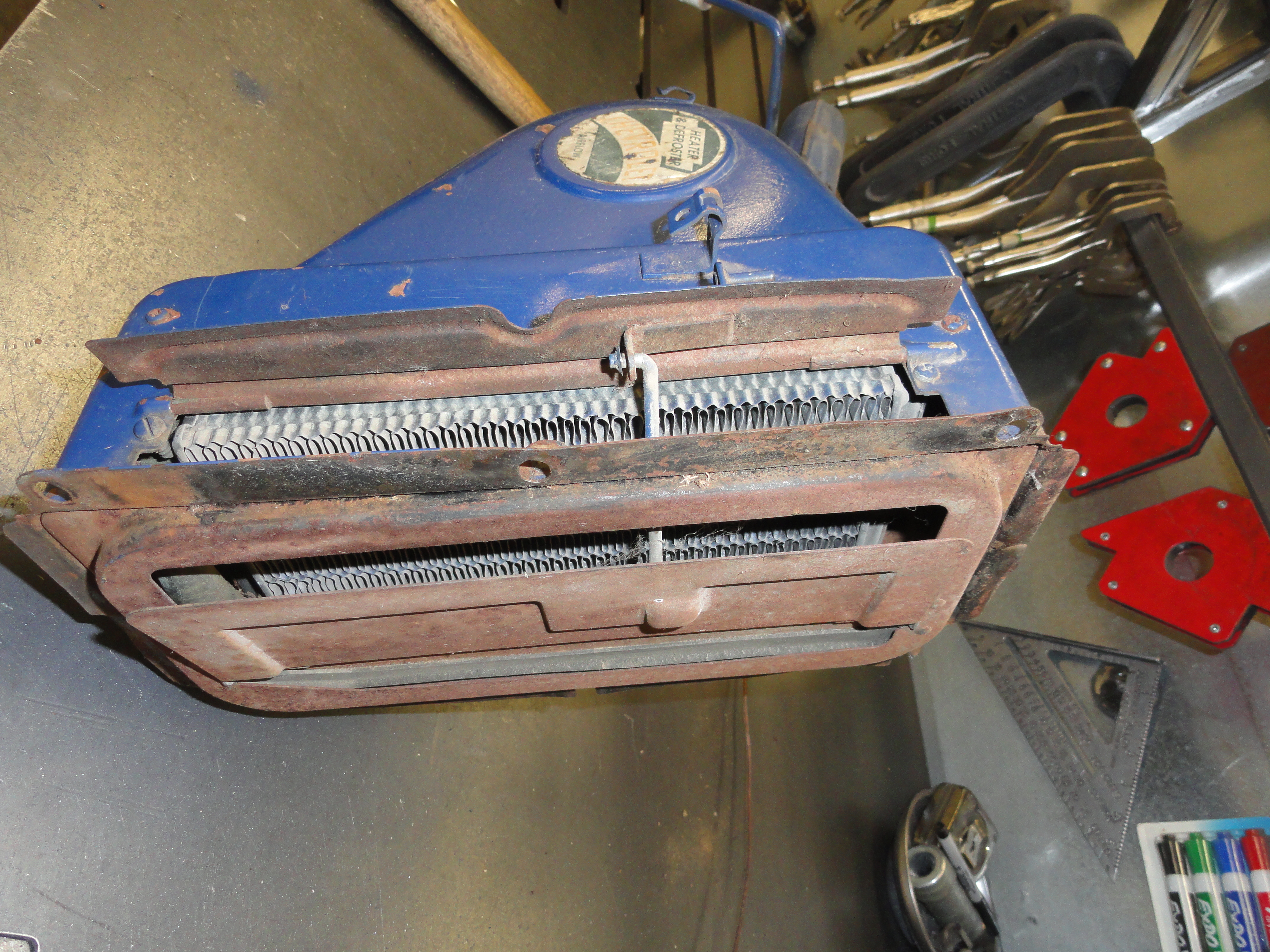
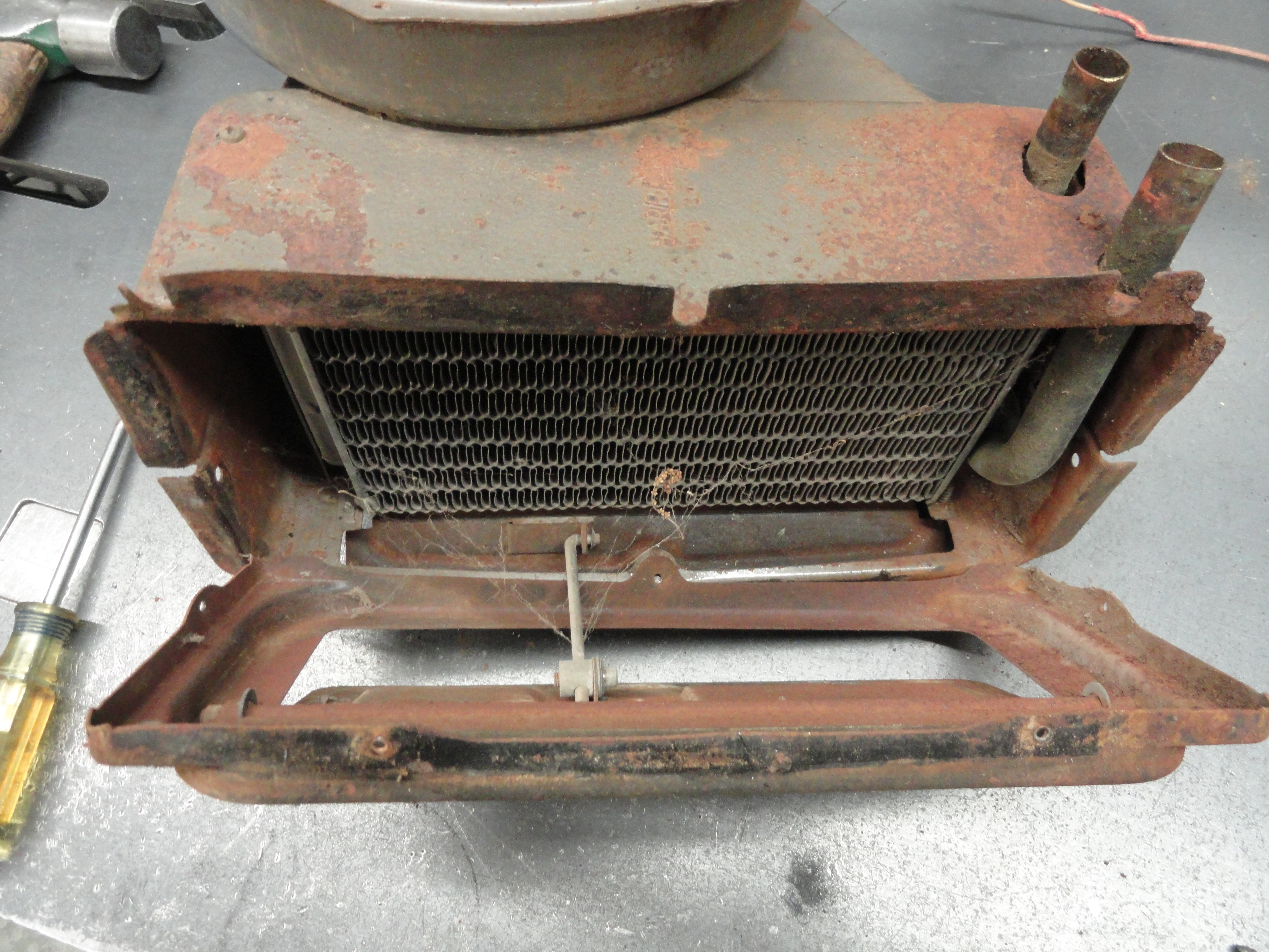
Here's a shot of the heater core and how it's installed in the housing. Turns out this core is good. You can test the core yourself by immersing the core in water with the outlets the only thing above the water level. With a few fittings and some heater hose, you can use a bicycle pump to pressurize the core. Plug one end off, then put about 8-10 psi into the core. Since you only have a 4 psi (or zero psi) radiator, it's more than enough. Any bubbles or telltale signs of damage, now is the best time to take the core to your local radiator shop for repair.
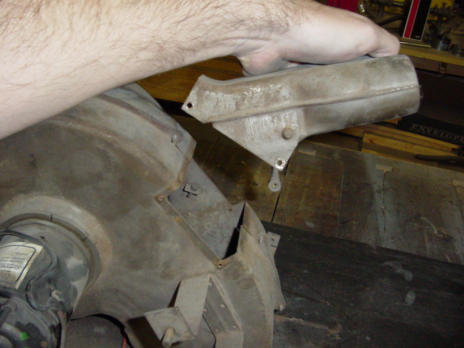
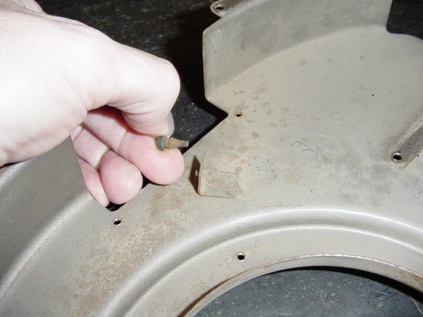
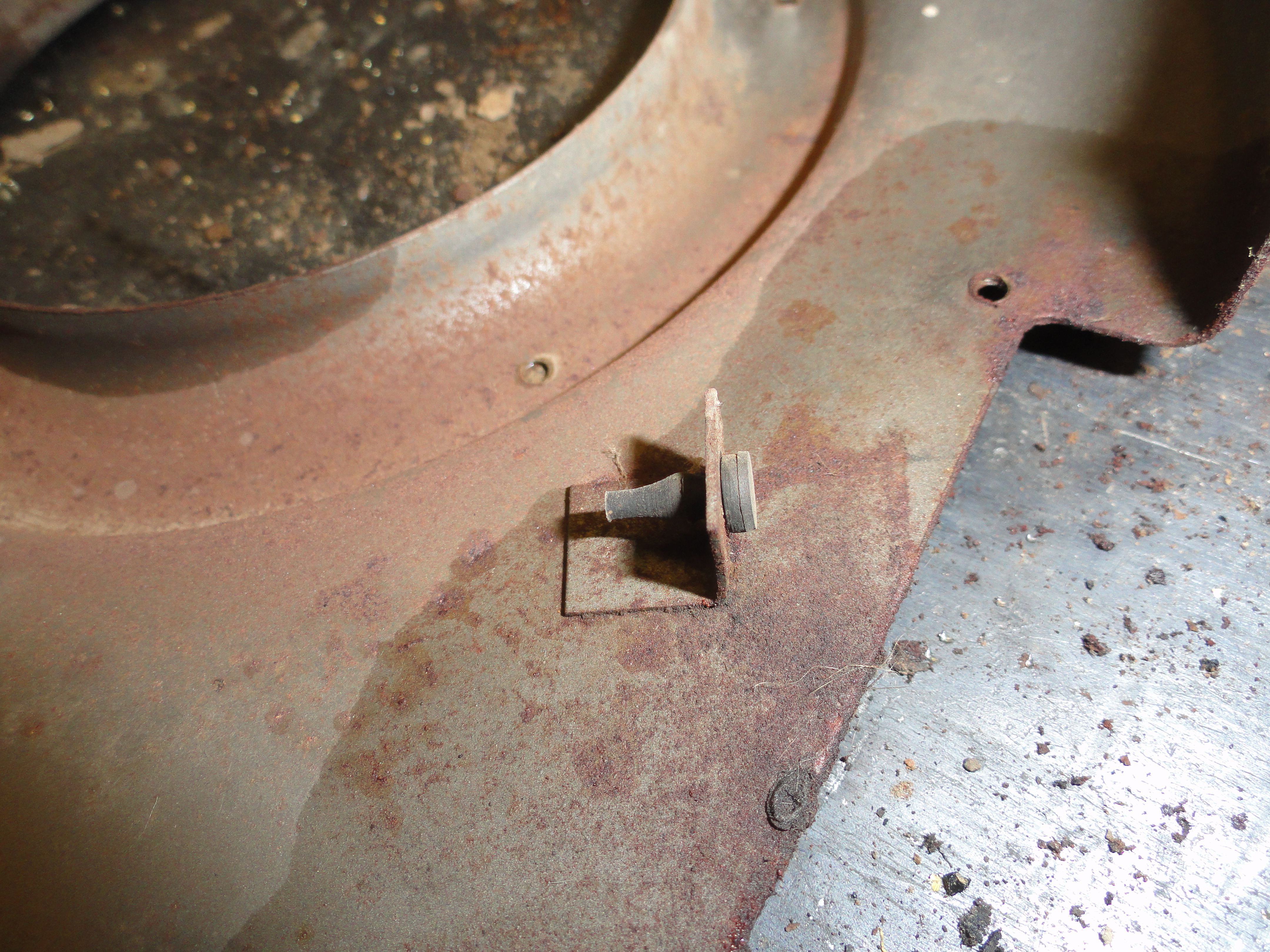
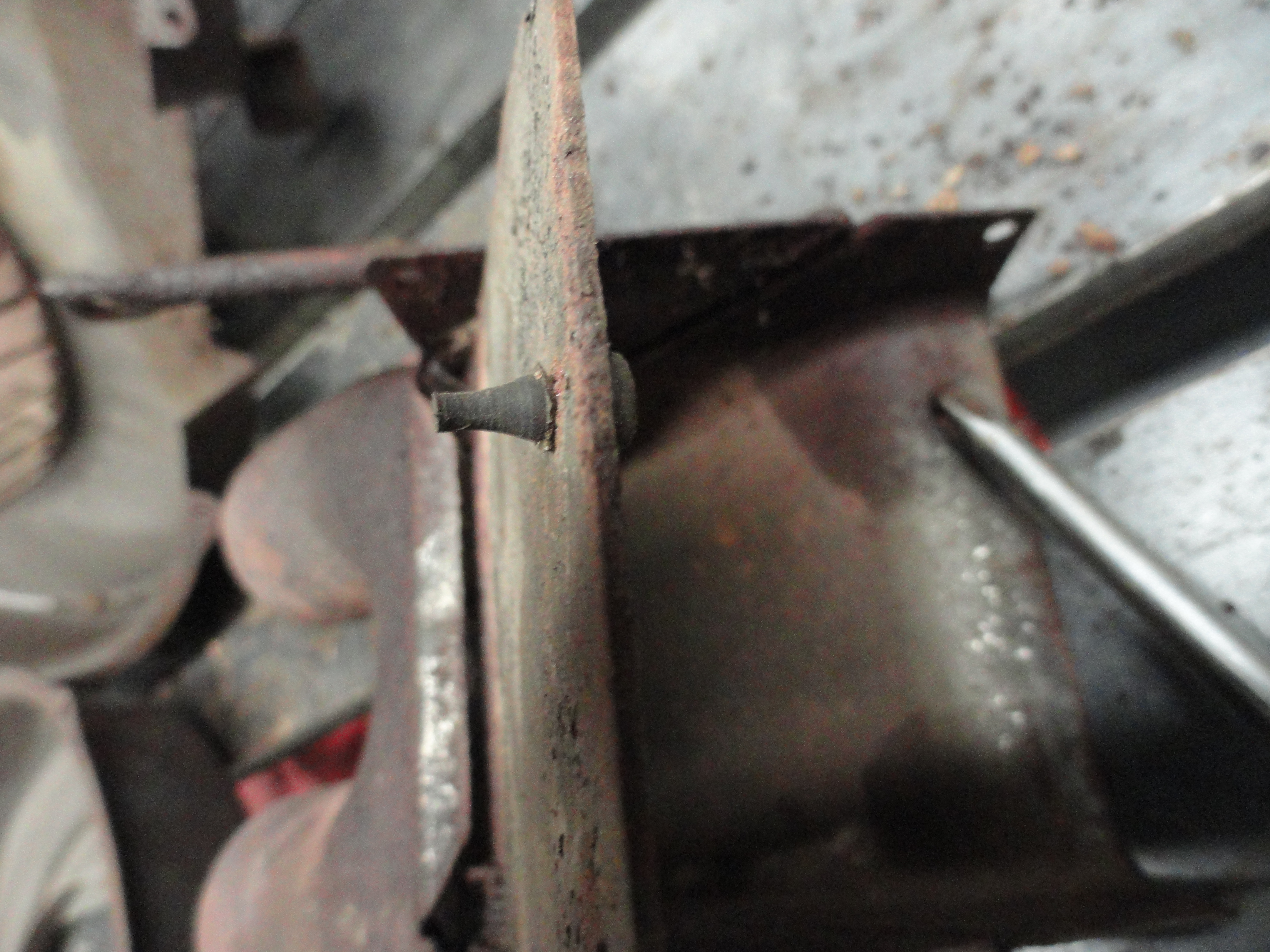
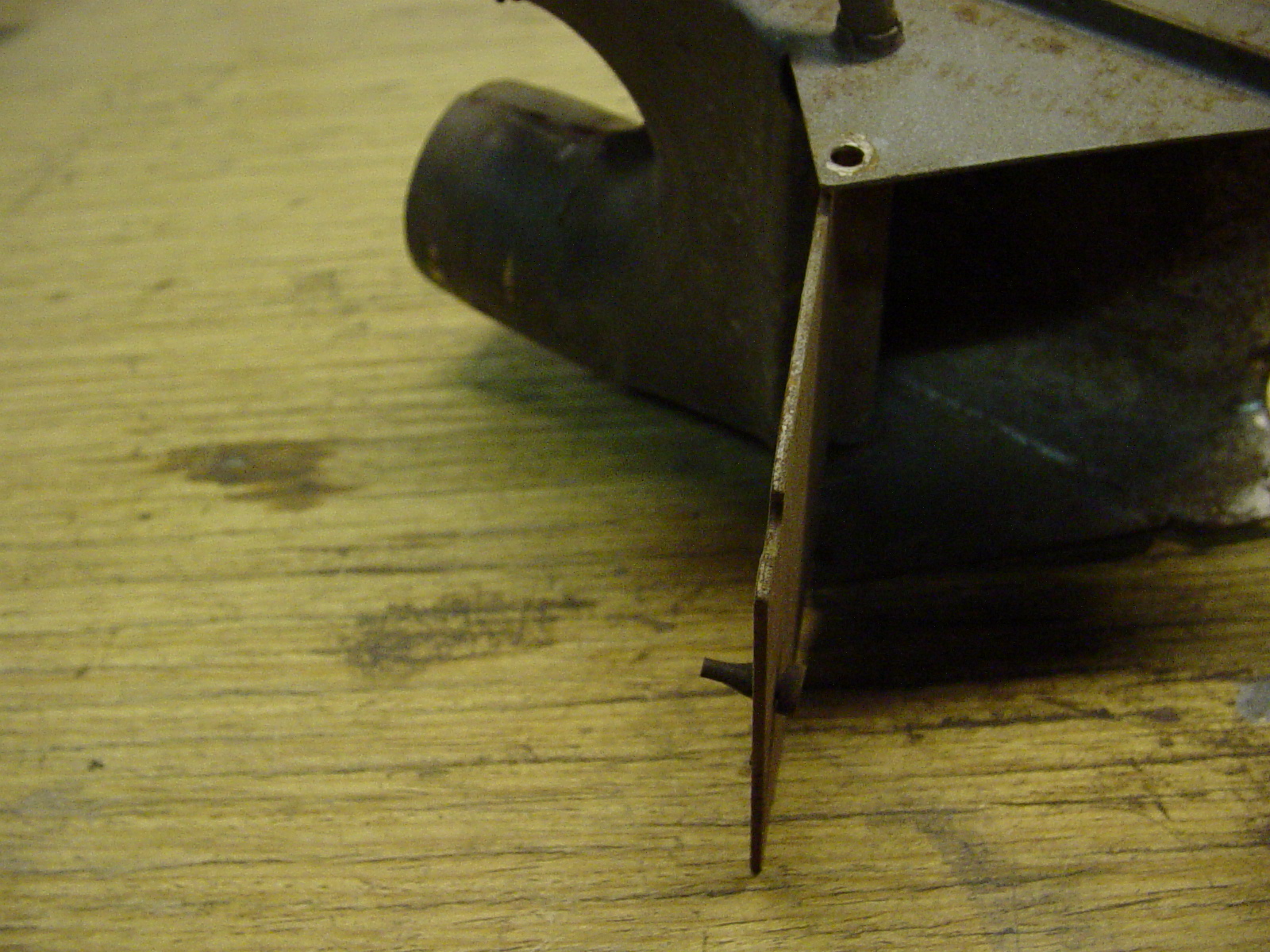
This is how the small duct housing is attached to the motor housing. In this picture and inside the main housing is a small
rubber bumper. This picture shows the direction that bumper needs to be reinstalled in. There are two of these bumpers in the
heater assembly. They are usually very brittle and not serviceable once you get them out. Fortunately, they are available in
two places that I have found so far. They are:
Marshall's Hardware
has them for about 69 cents each. The part number is 0505510.
Steel Rubber Products has them for about $1.00 each.
The part number is 33-0127-41.
You want to take great care and use unusual finesse in removing these bumpers if you have any hope of keeping them. They will need
to be removed for the re-painting process. I realize this picture is too small to see them (Click on the picture for a larger one),
but trust me, they are there.

This is how the two halves of the core housing are assembled. Just about everything involved in this project is fastened with #6 x 3/8 inch Phillips Pan Sheet Metal Screws. Buy new ones; they are cheap. I go the extra mile with hardware. I get stainless steel screws for this. Available at McMaster-Carr.

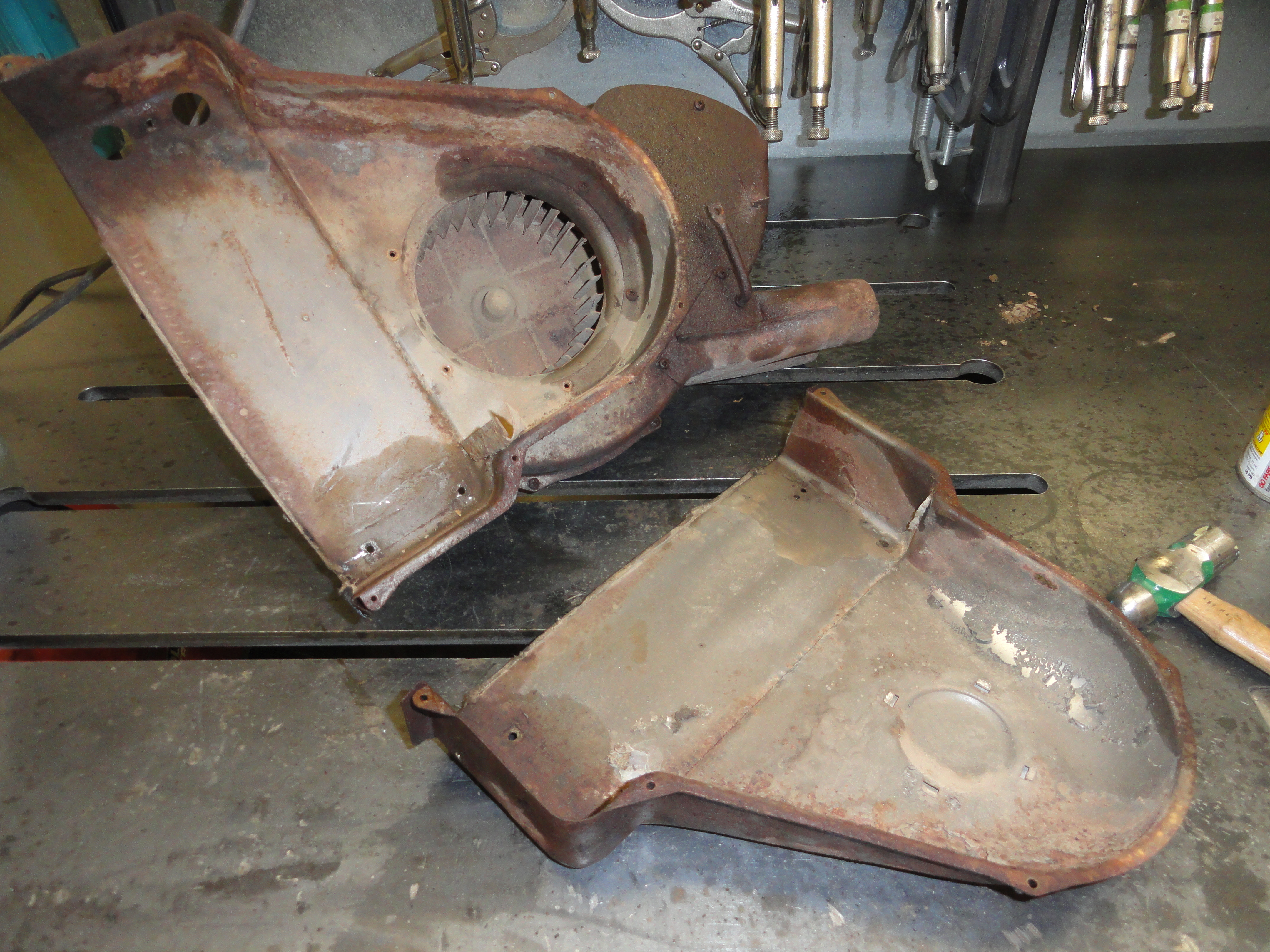
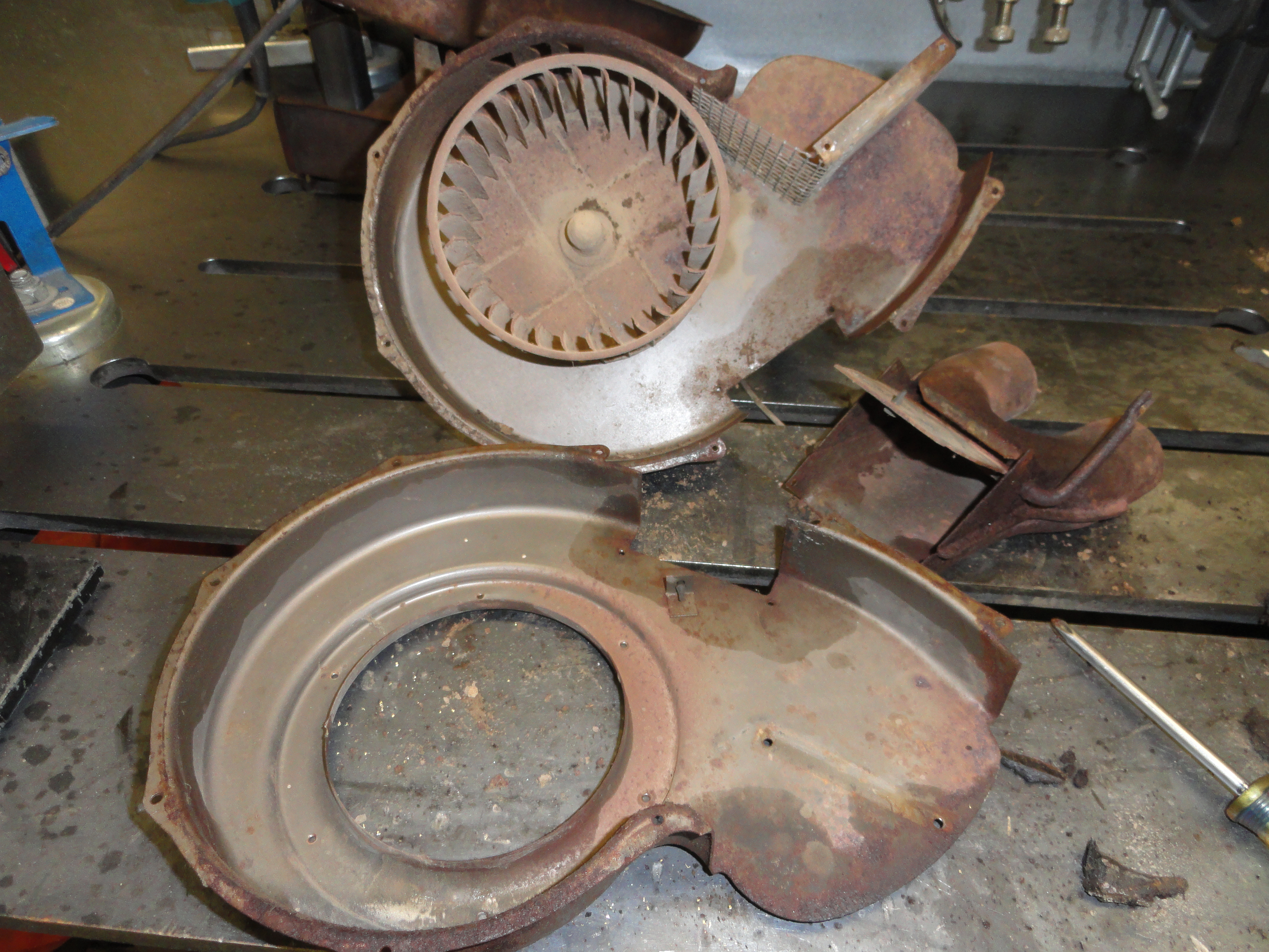
Here is the rest of the core housing removed from the motor housing. There are no gaskets in between the two.
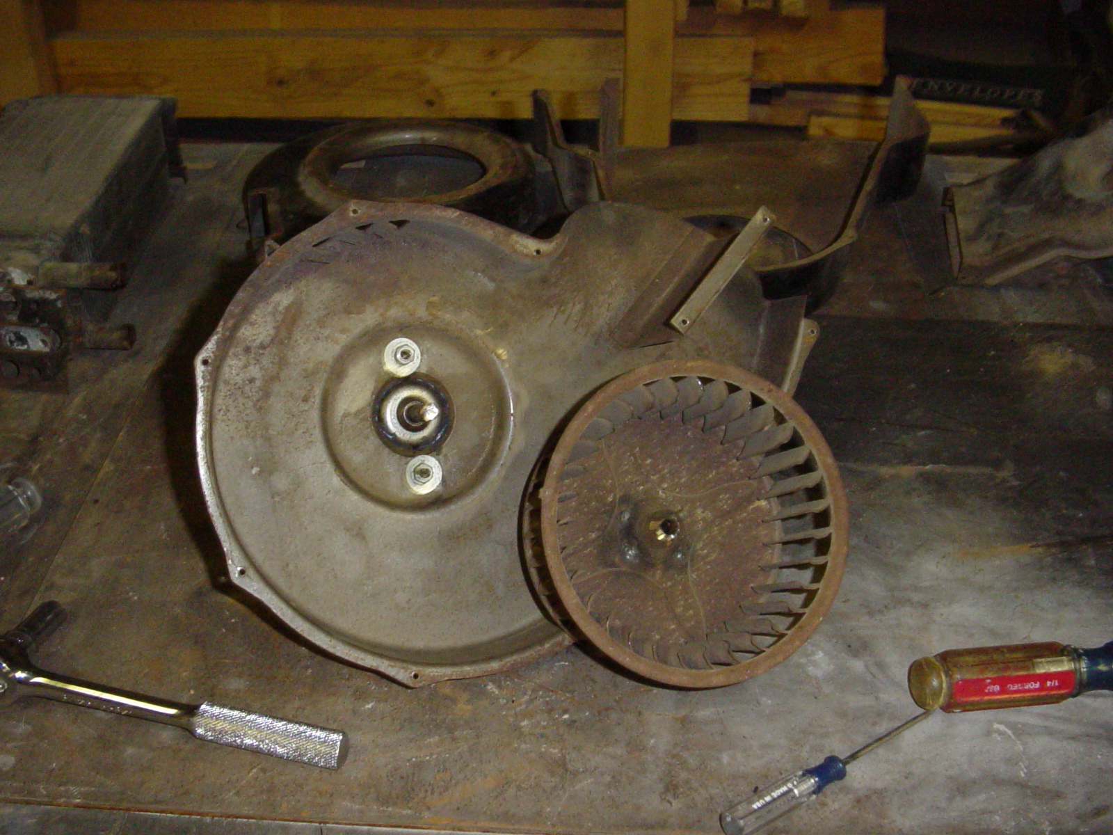
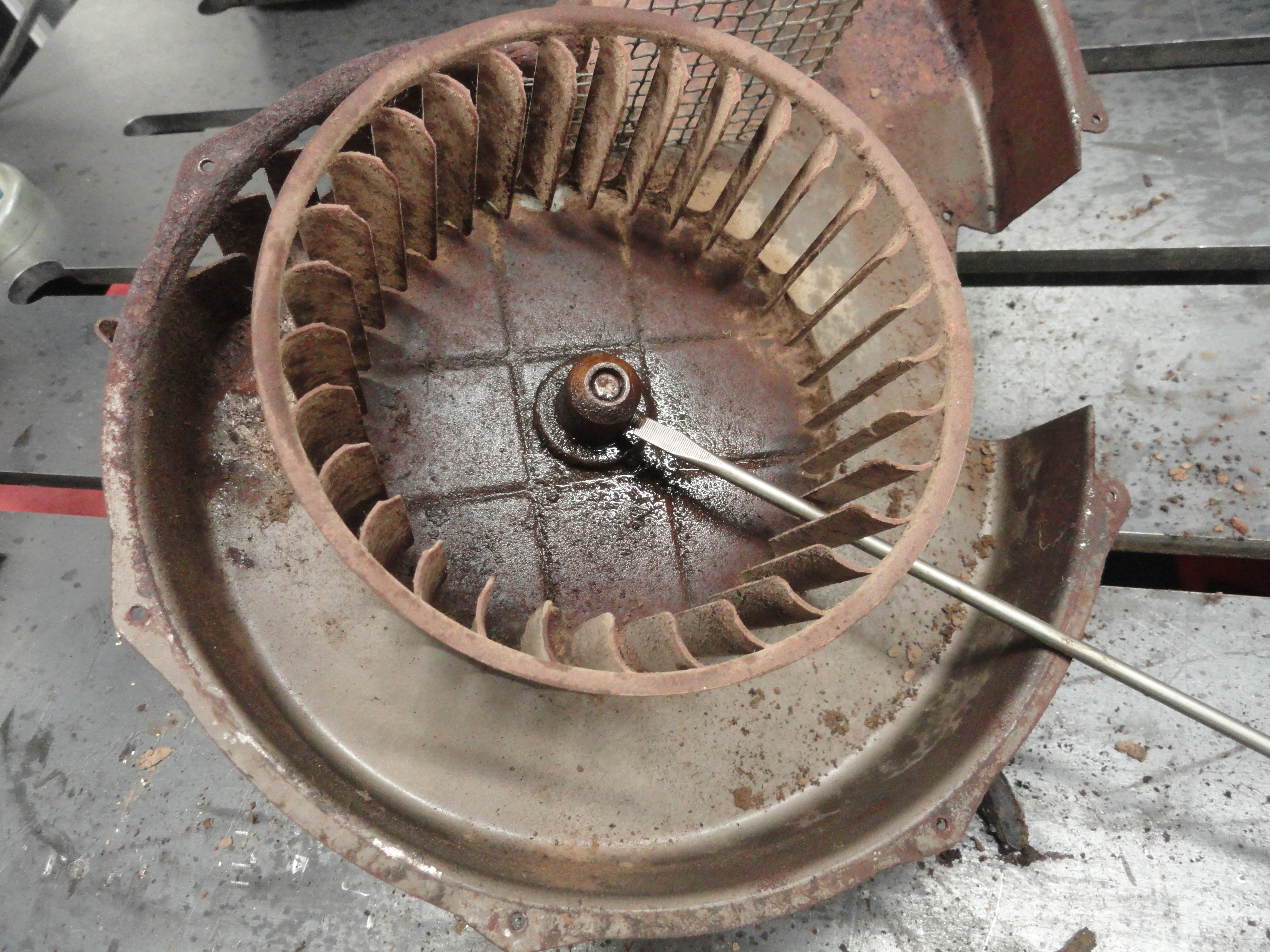
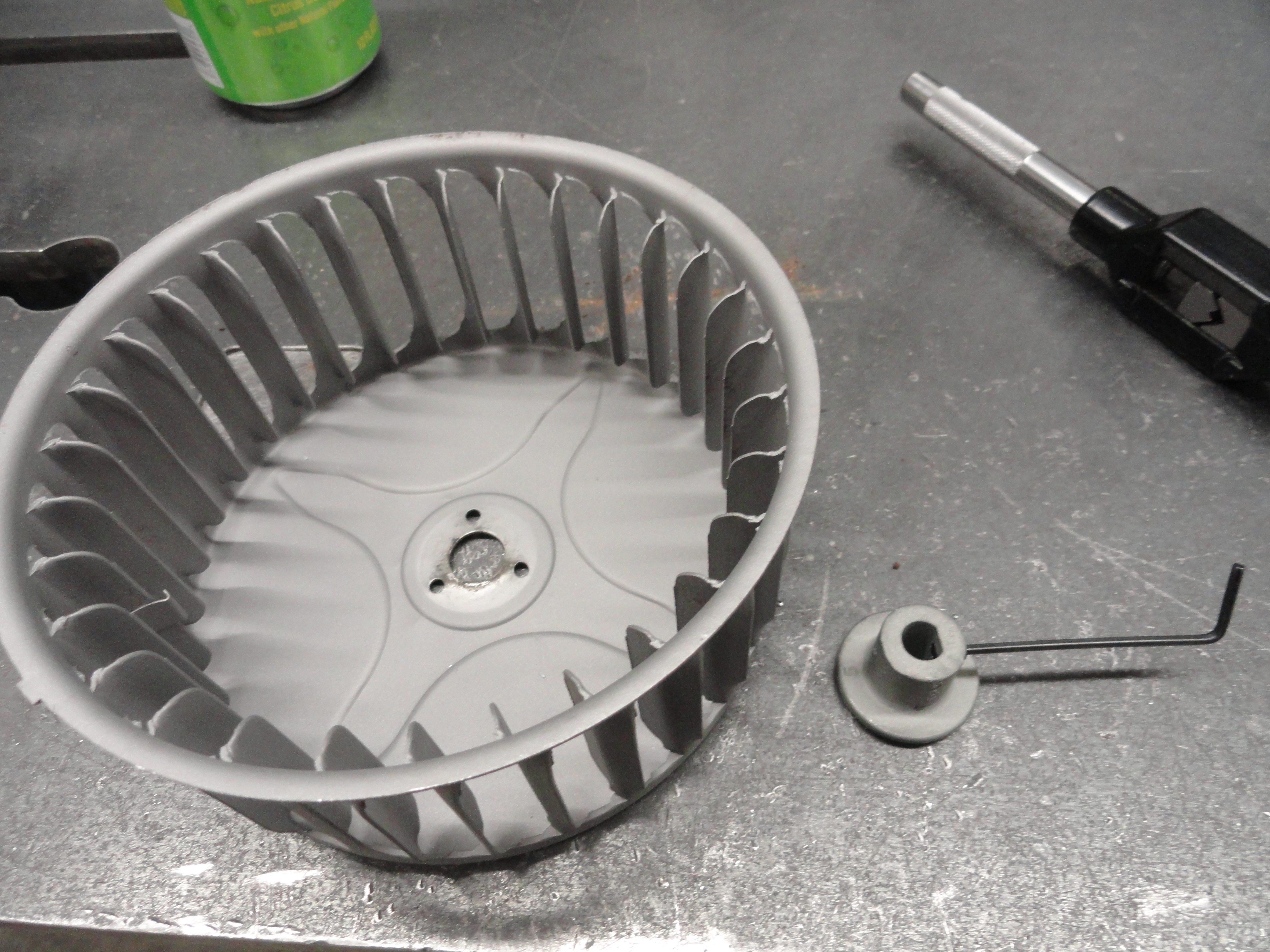
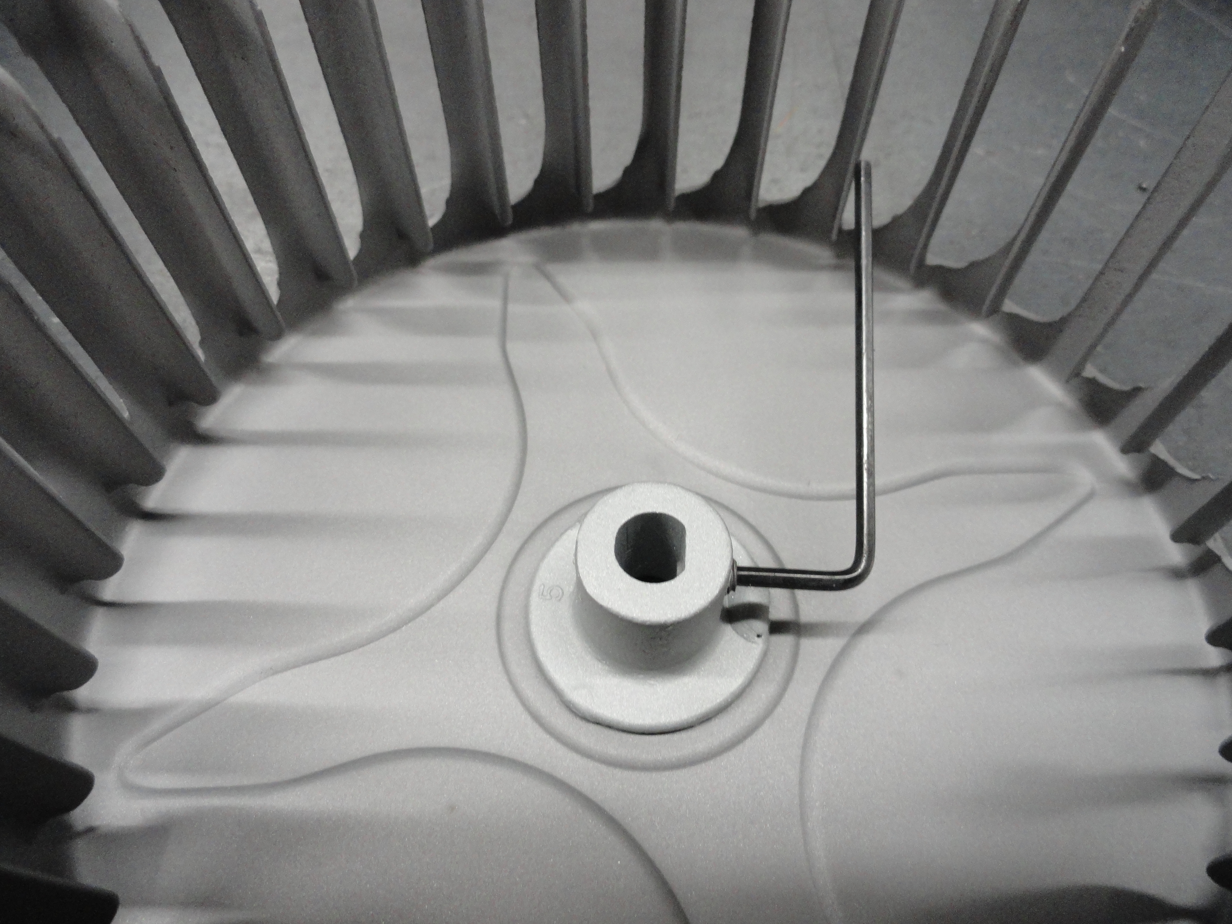
This one is with the fan assembly removed. This is no big deal really. There is a slotted set screw on the side of the shaft and all it takes is loosening that and then a little persuasion with a punch and the fan will come right off. Be careful not to beat on things too hard since it is very possible to bend the fan assembly.
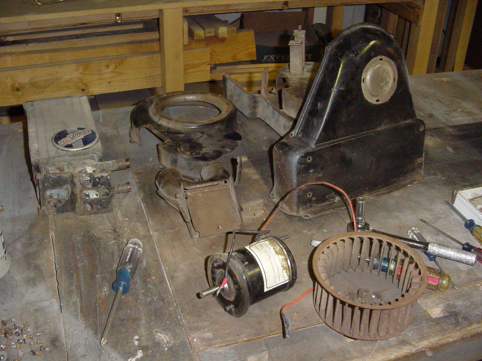
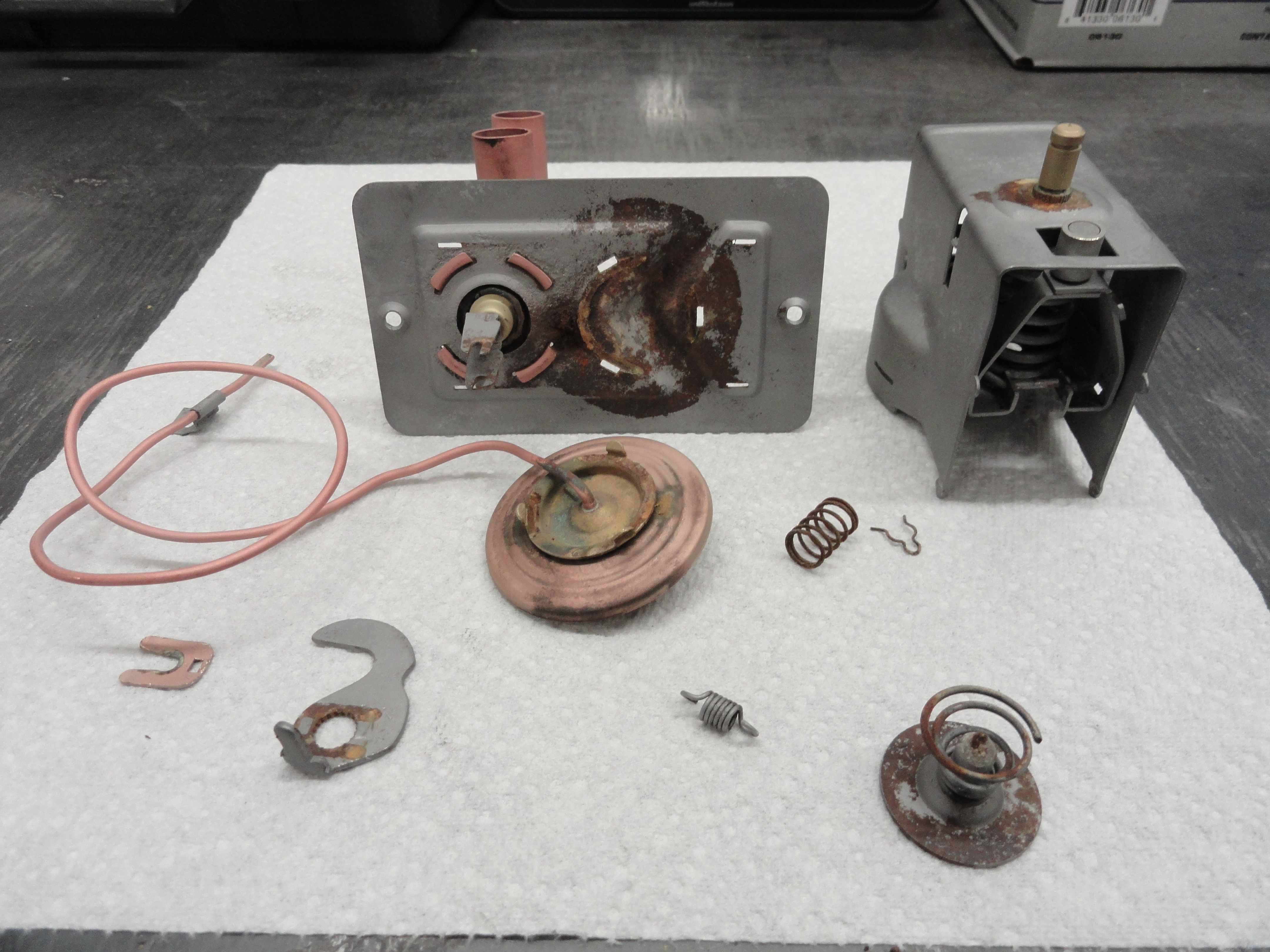
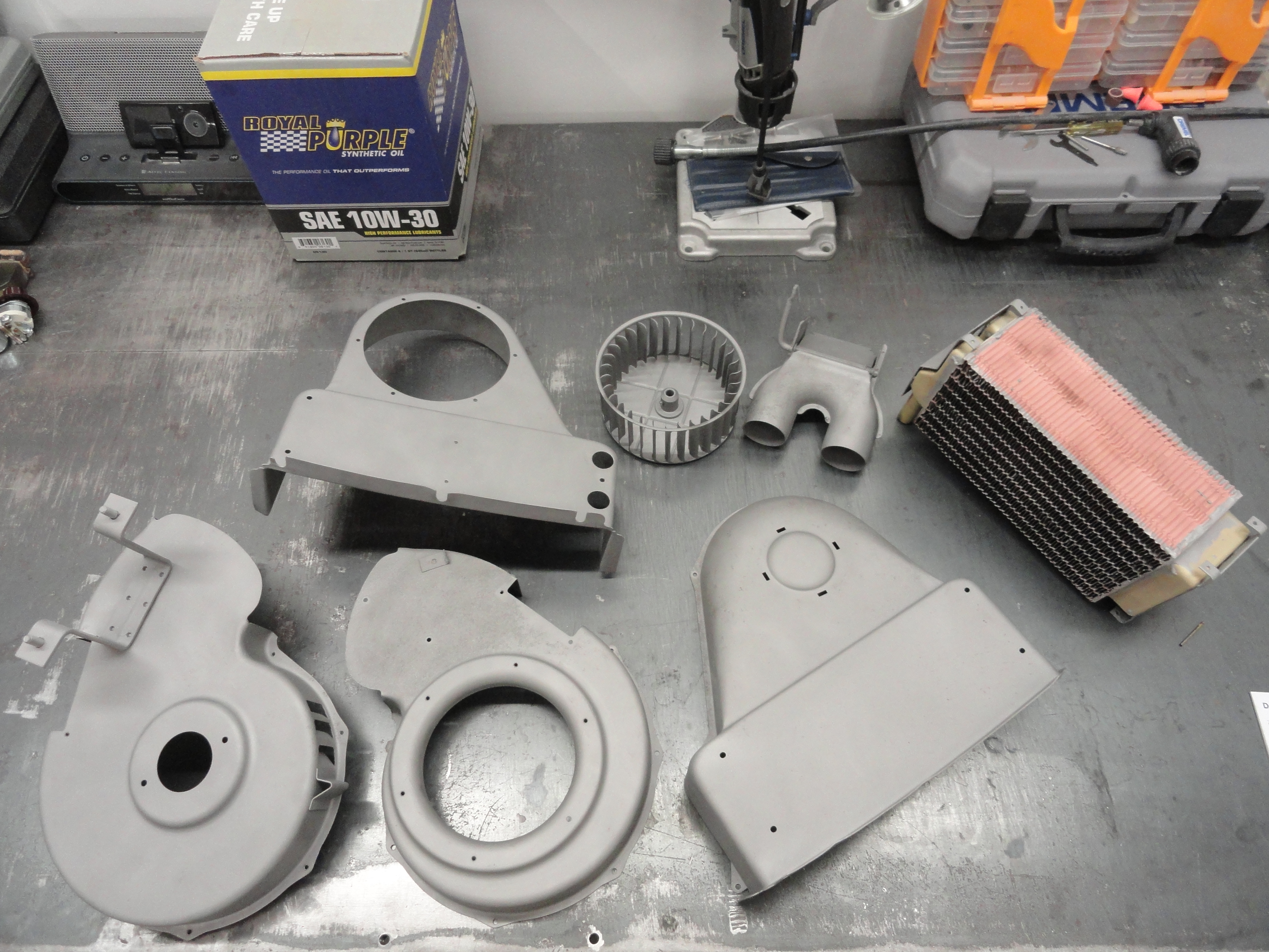
This is the entire heater disassembled. Not a lot to it, but these pics should help in getting it all correctly back together. In case you can't see enough detail, you can click on these pictures to make them much larger. They are in 1200x1600 high resolution.
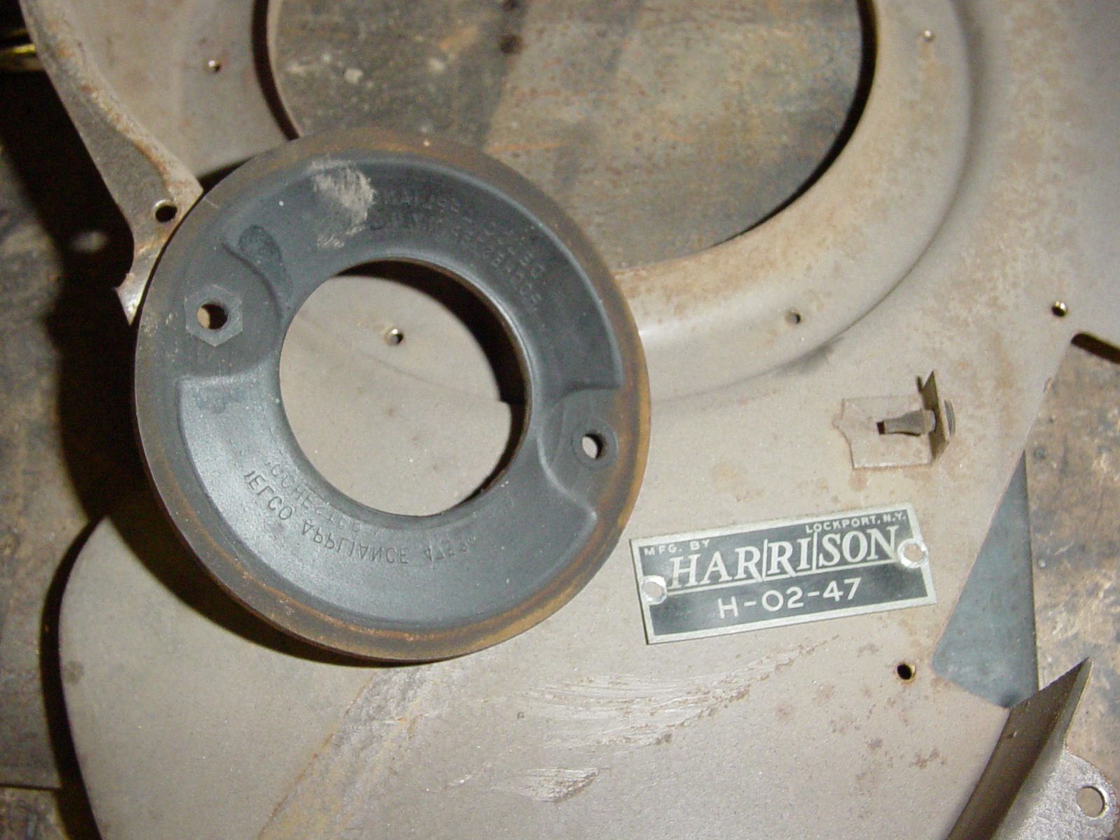
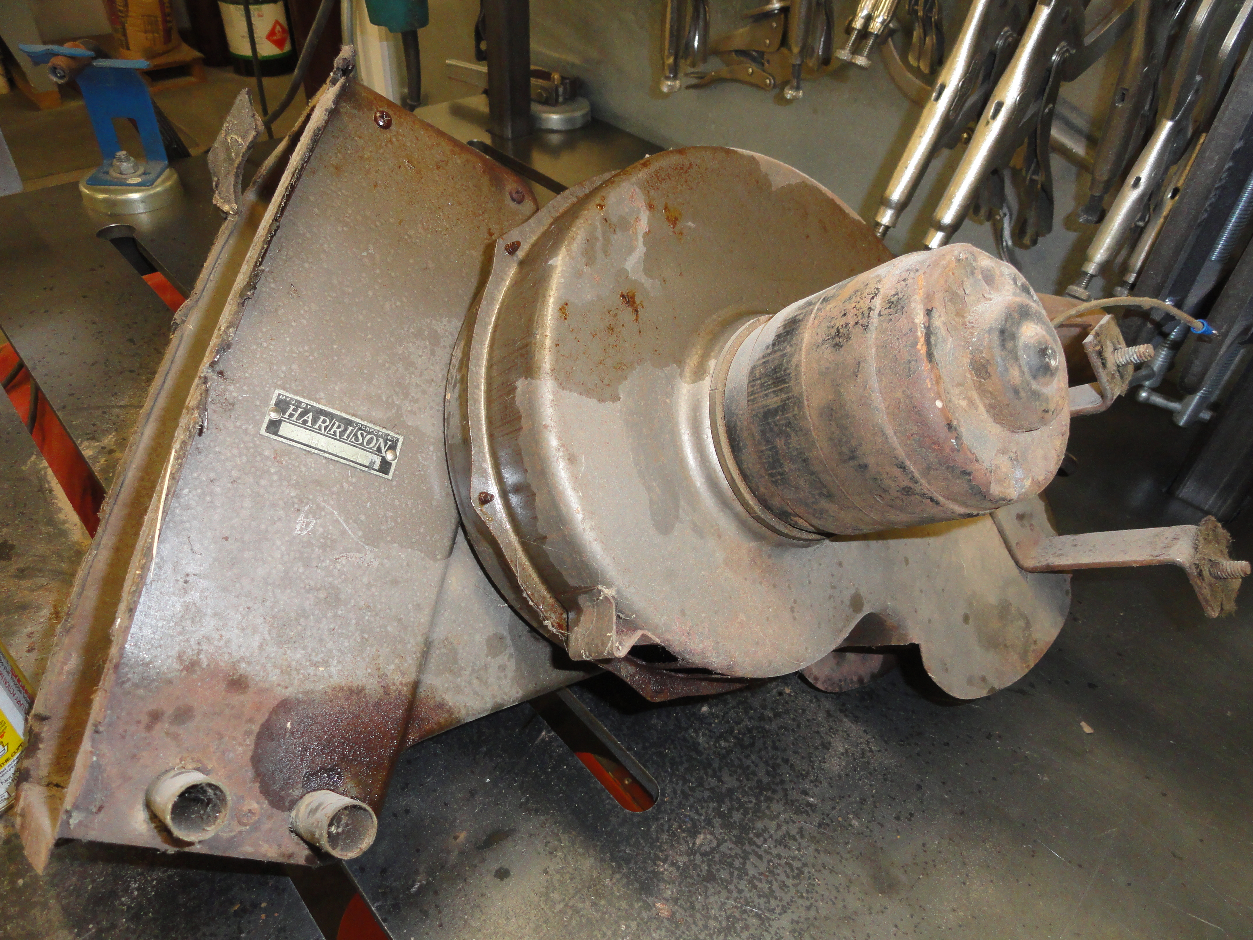
This is to show a few things - what the Harrison Faceplate looks like exactly, what the 'motor to housing' gasket looks like, and the placement of the aforementioned rubber bumper. There are two of them pesky rubber bumpers. Here is where the other one goes. Again, take care in removing them if you choose to keep them.
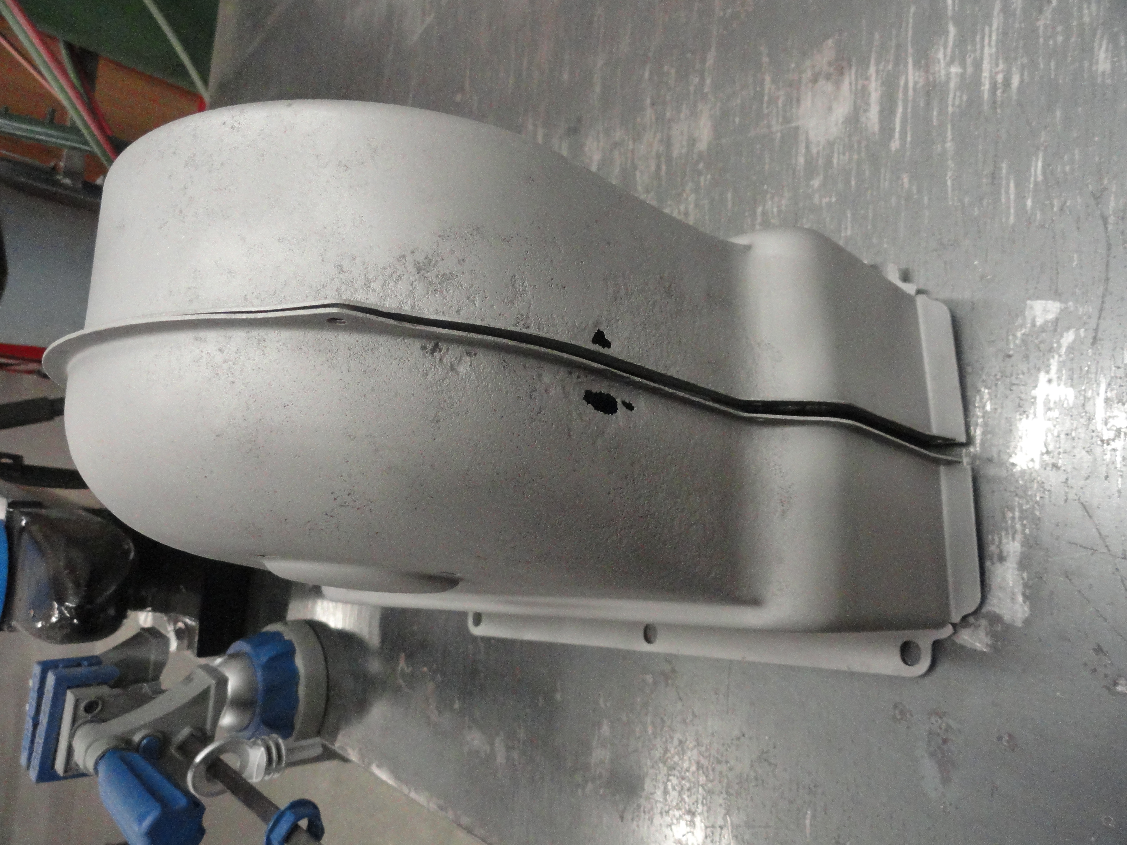
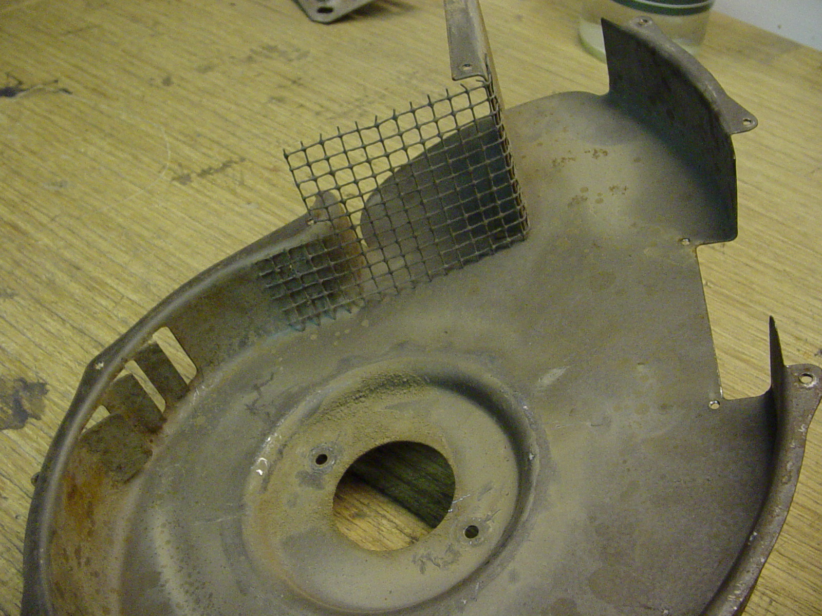
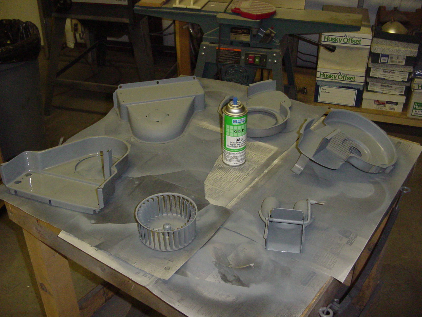
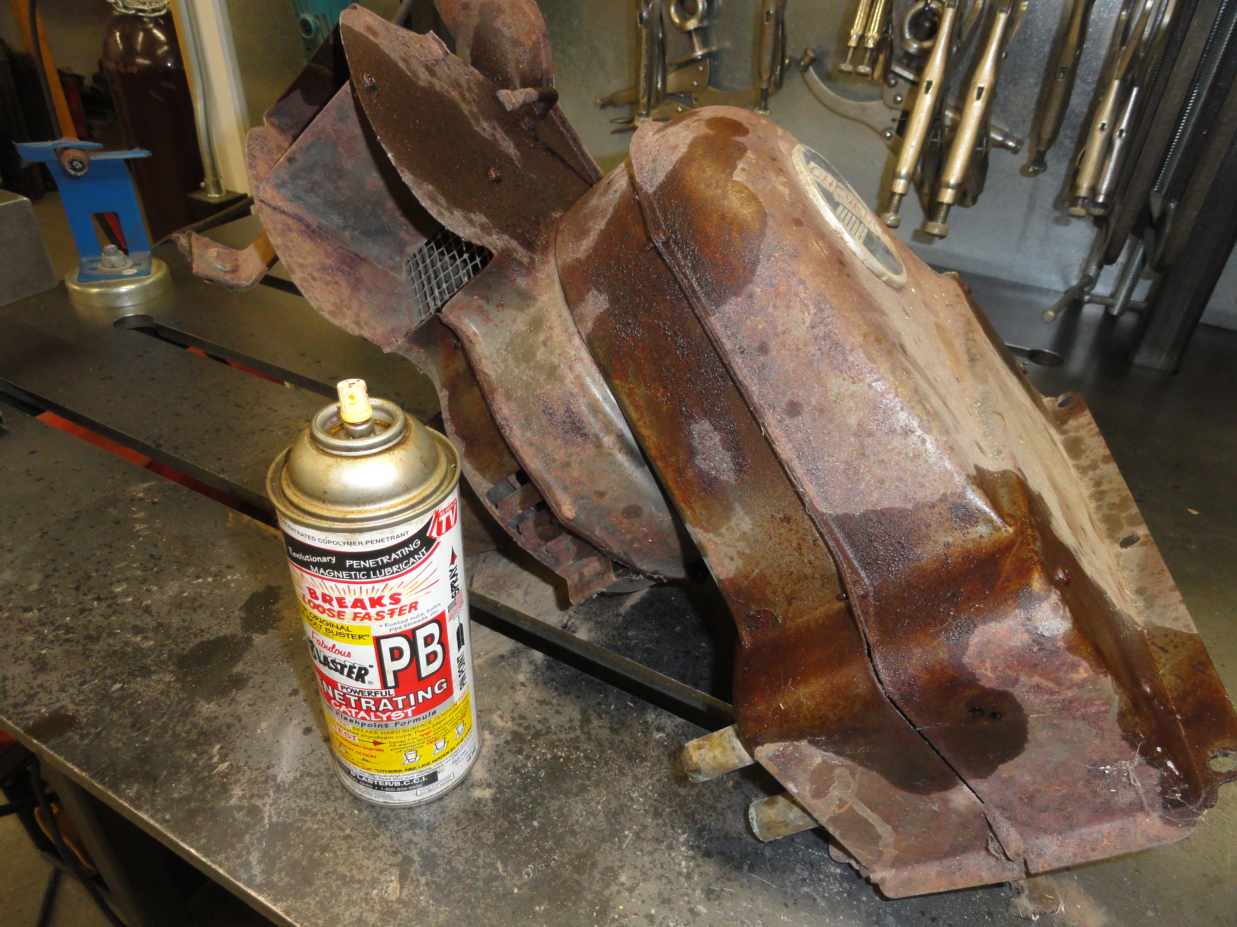
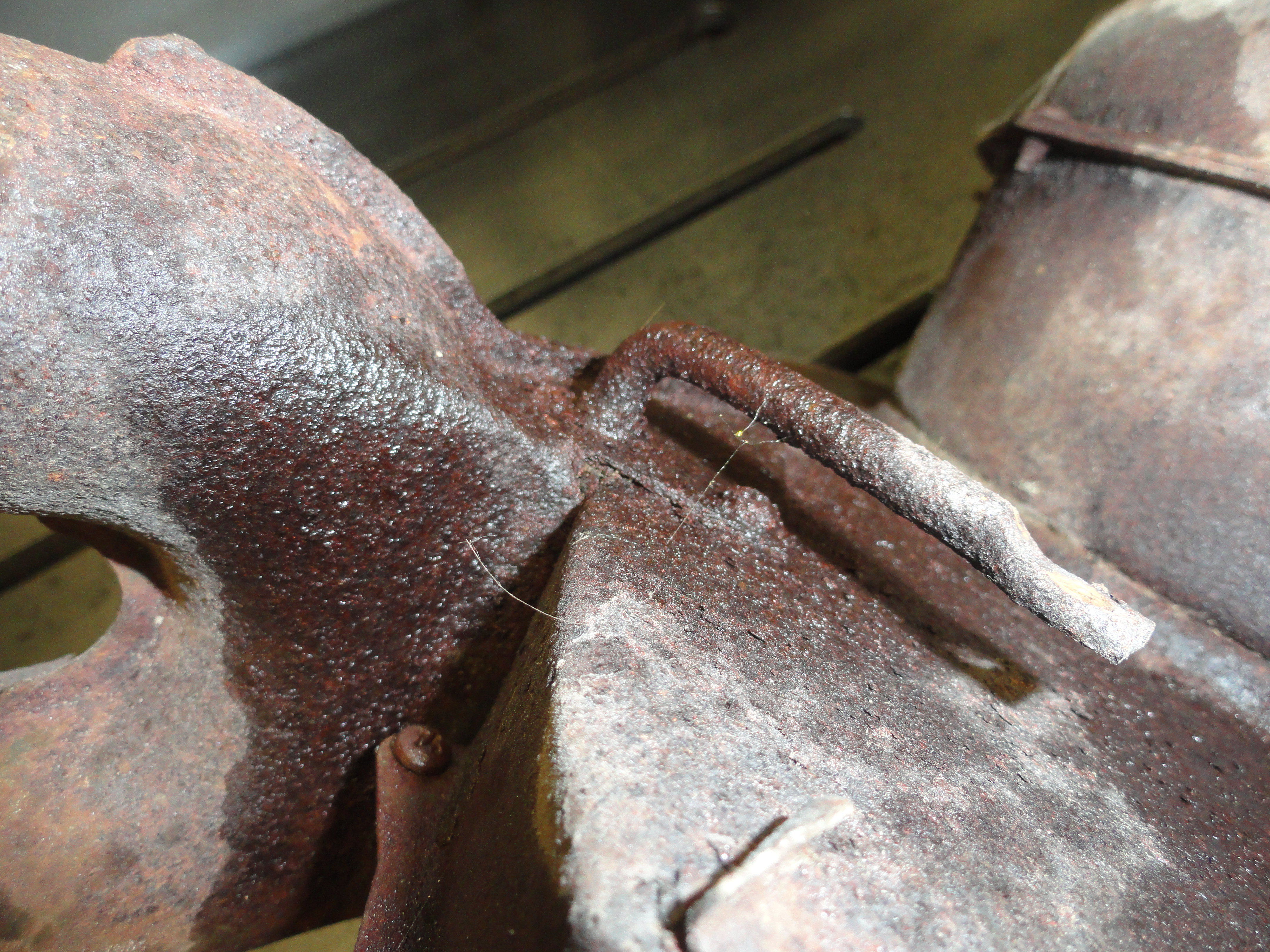
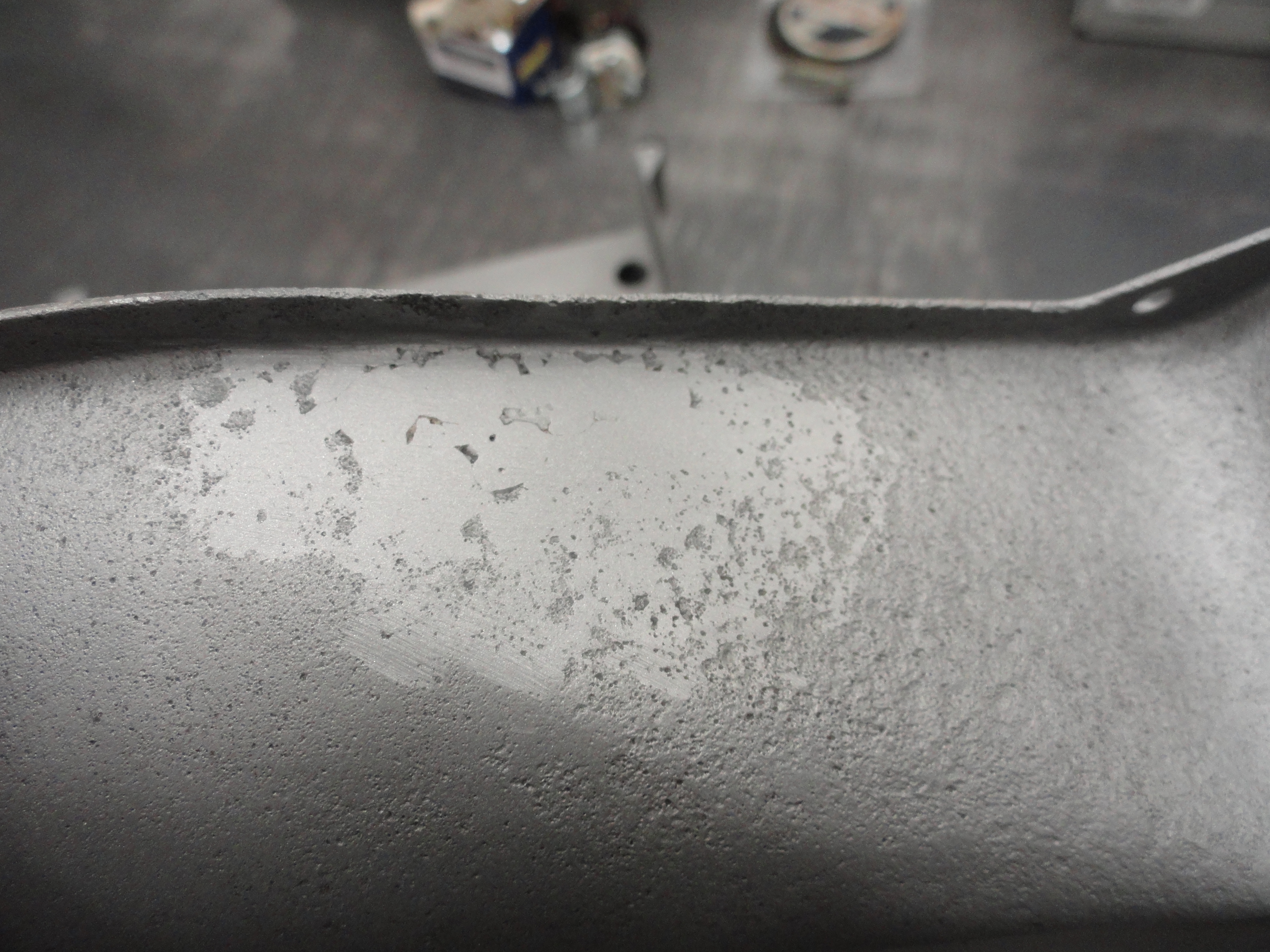
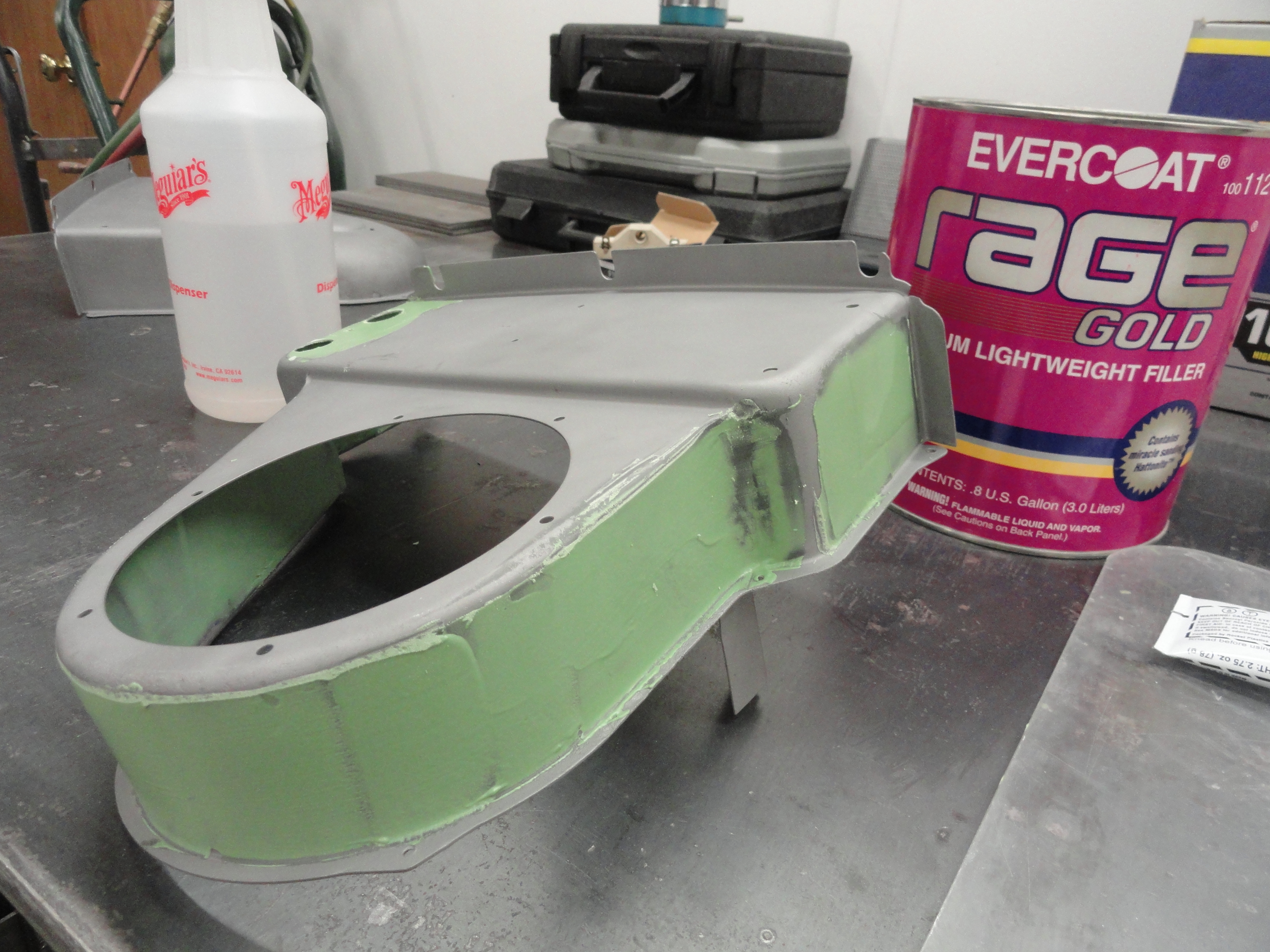
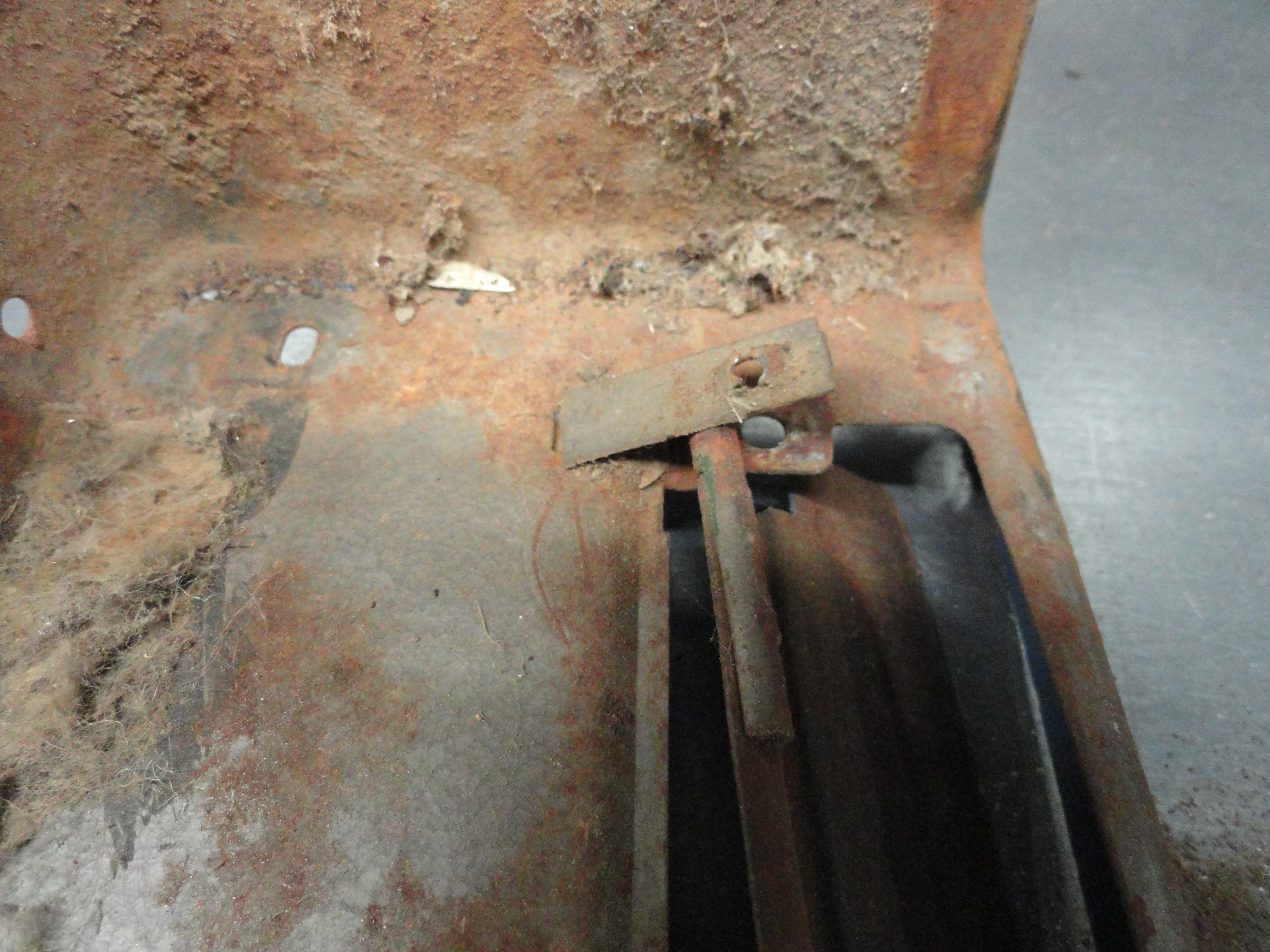
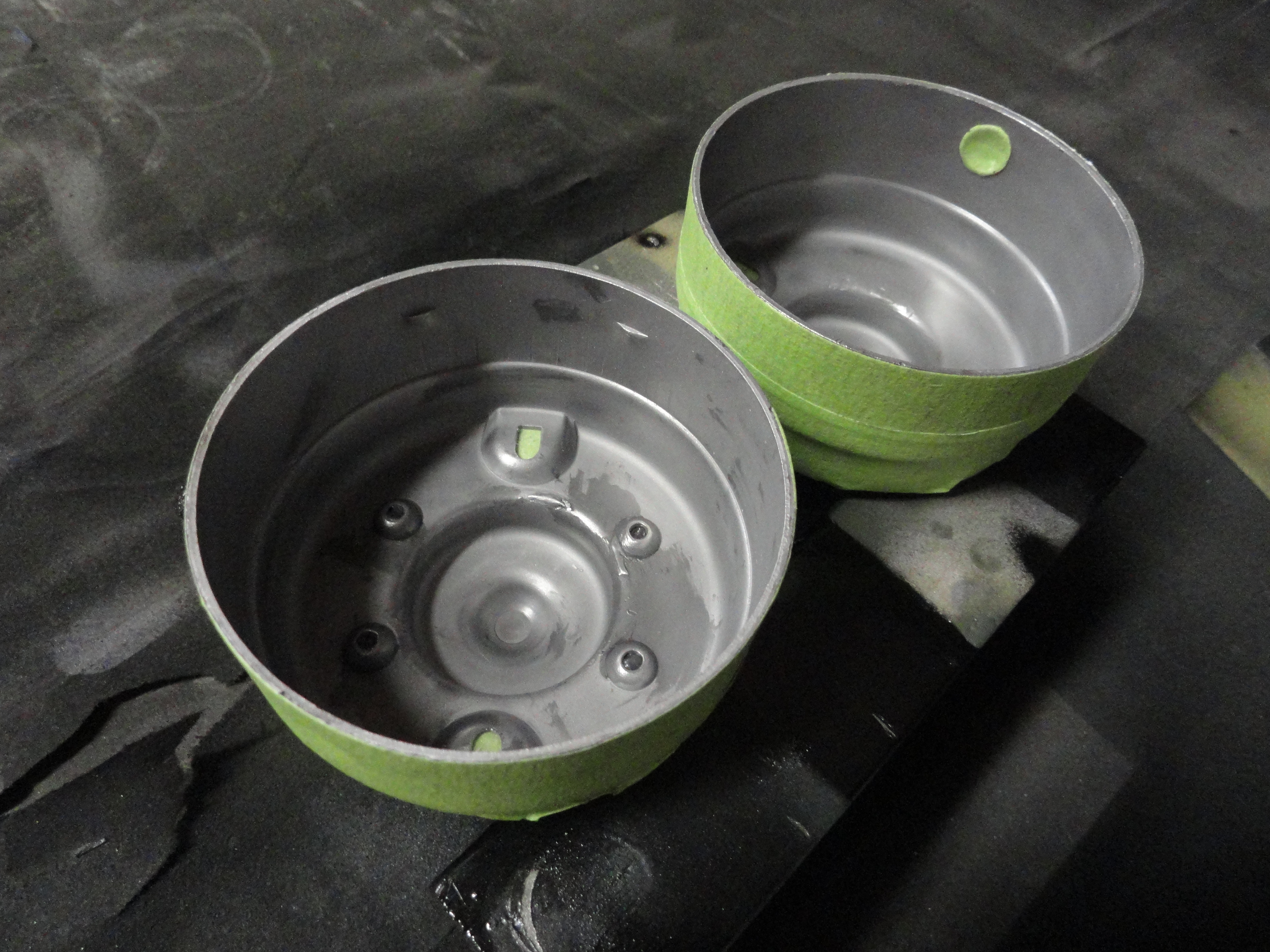
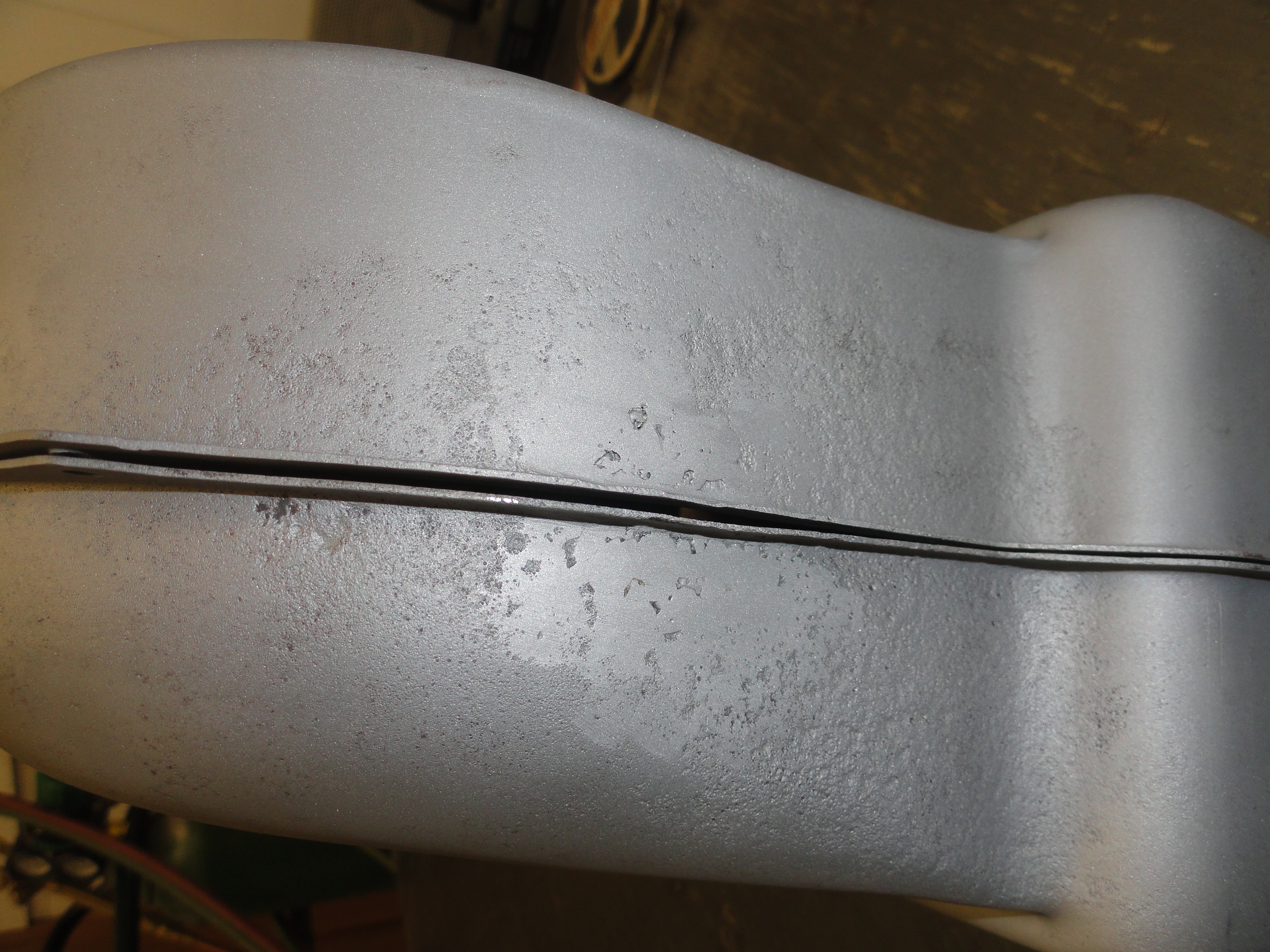
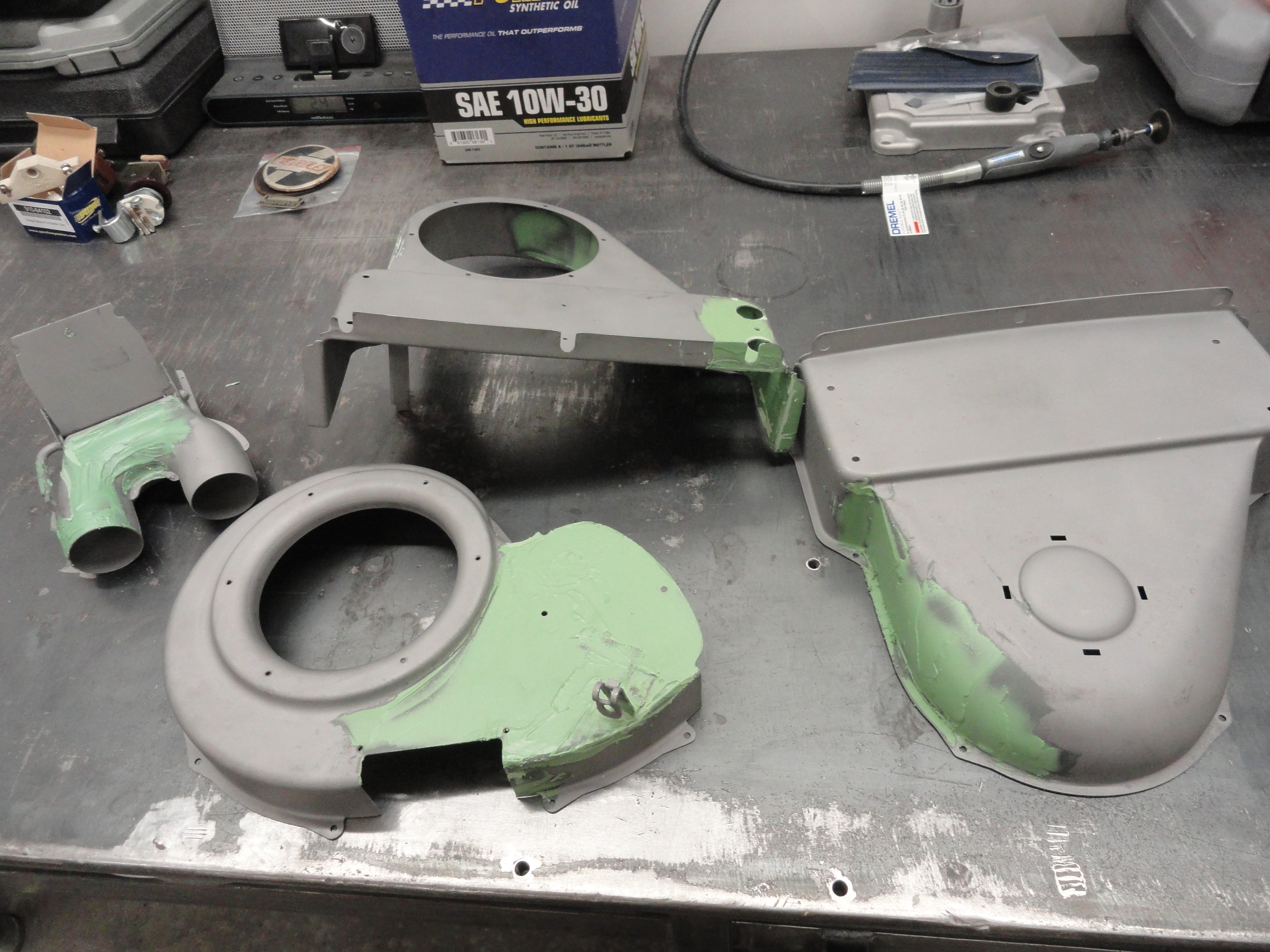
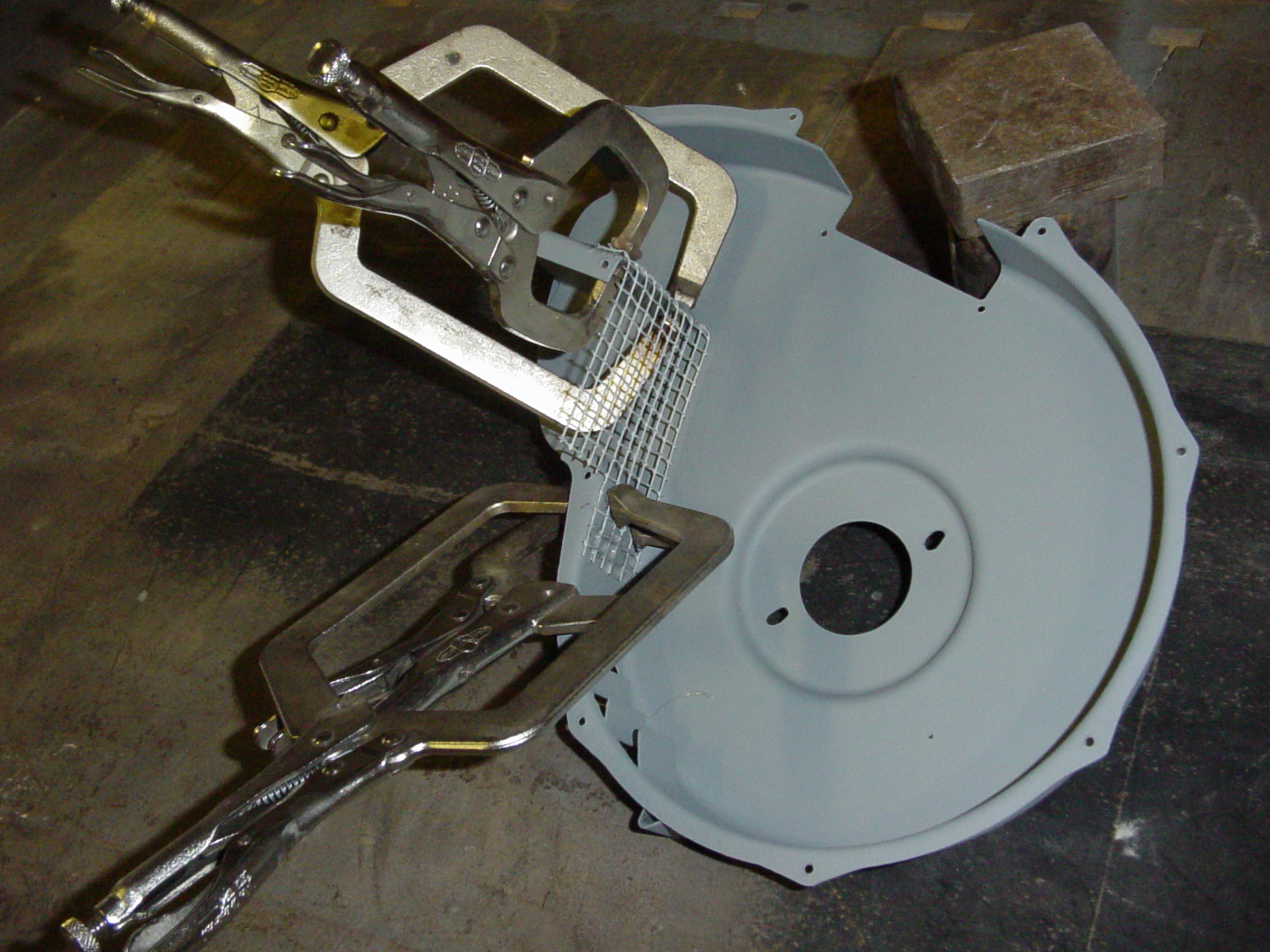
The picture on the left is all of the parts fresh out of the Blast Cabinet. No old paint or rust is left after blasting. This reveals rust pits that we couldn't see prior to blasting. Rather than painting over it and calling it a day, let's address these problems further. The picture on the right is to show what can happen when there is a leak in the cab over time. We will repair this damage as well before going further.
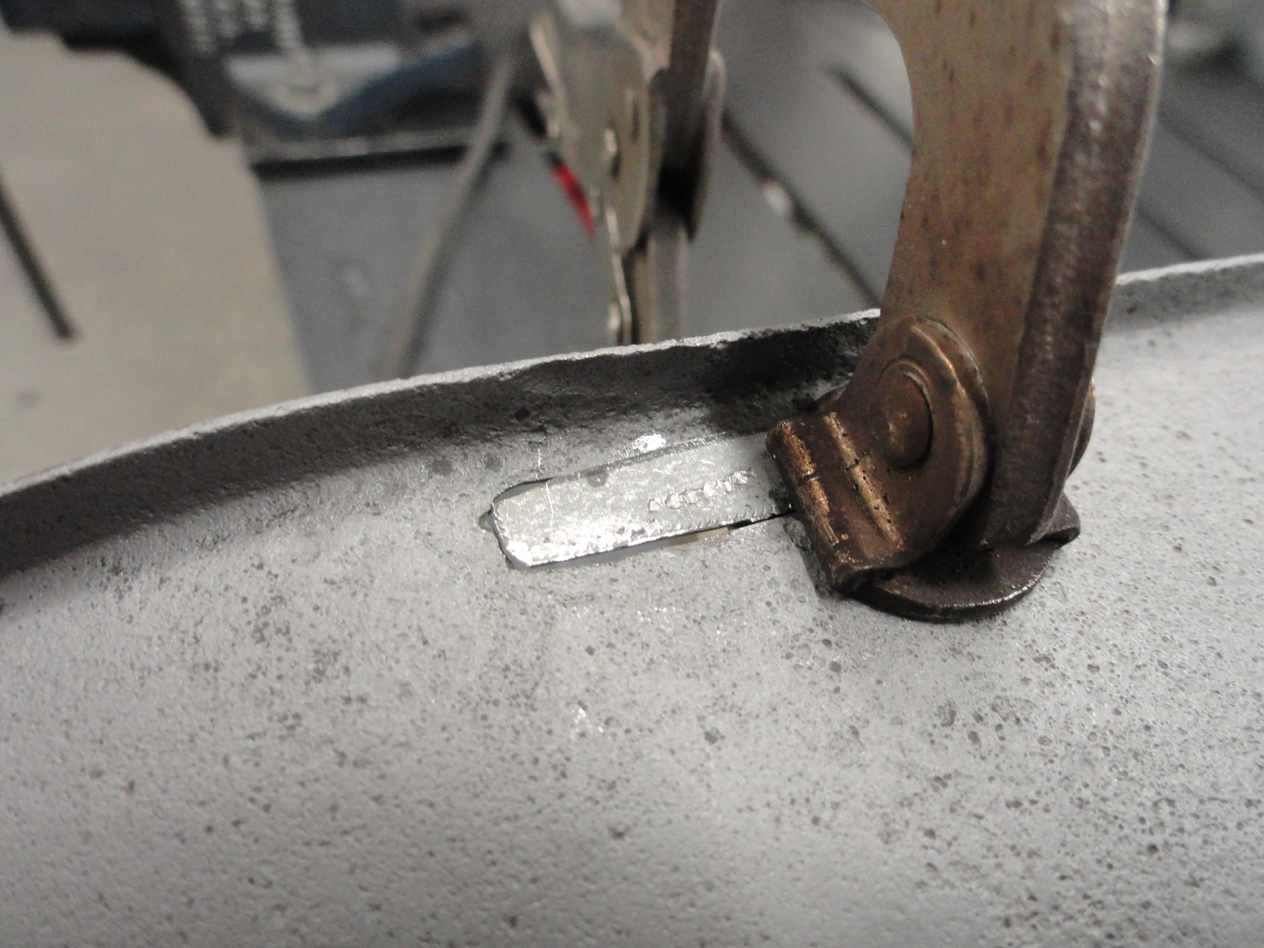
This was just a matter of making the hole more rectangular and putting a small piece of 14 gauge metal in place and welding it in. Be sure to set your MIG welder to a low temperature setting appropriate for thin sheet metal or you will have more holes instead of less! This butt weld looks like it isn't even there on both sides of the work.
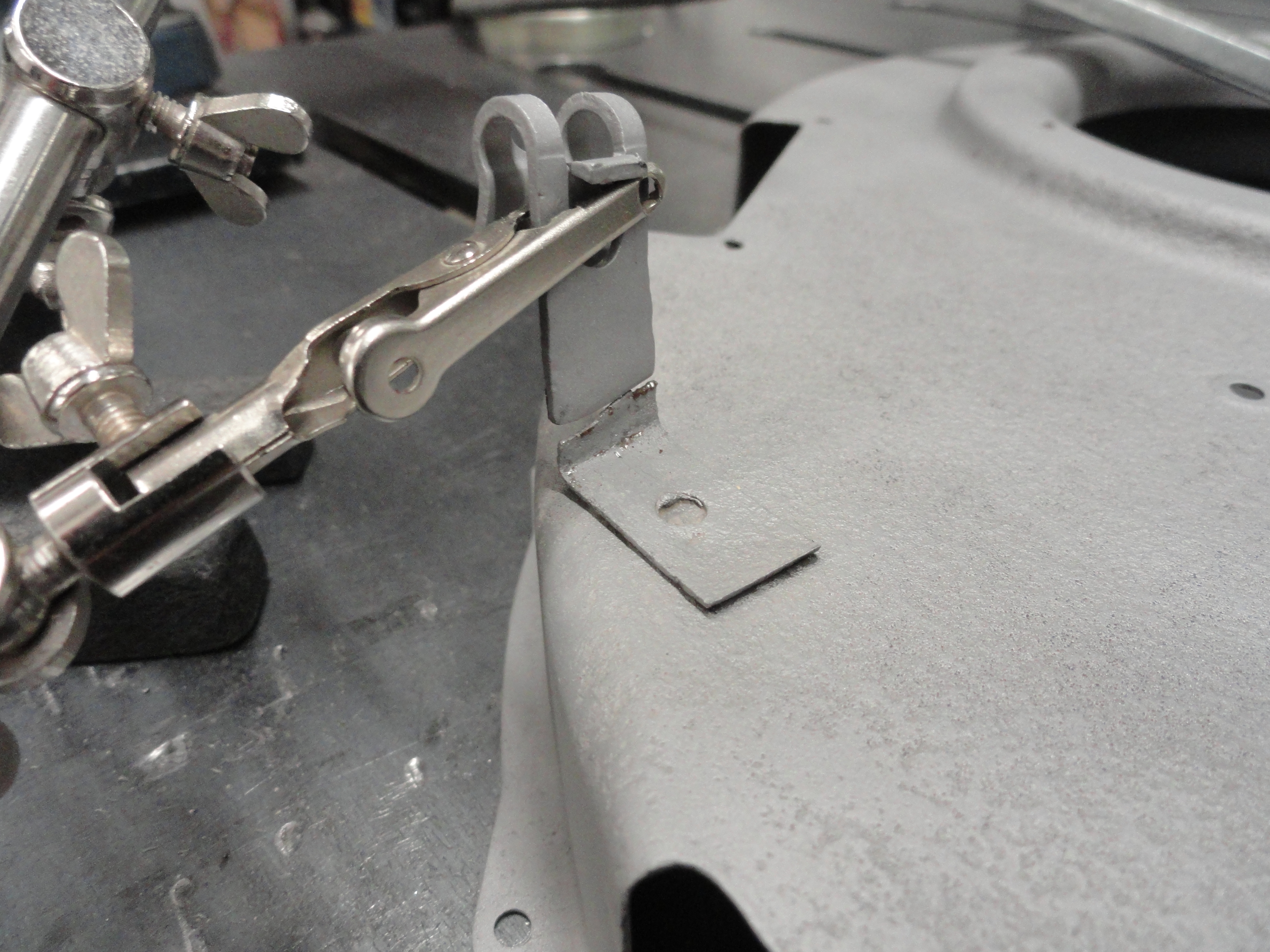
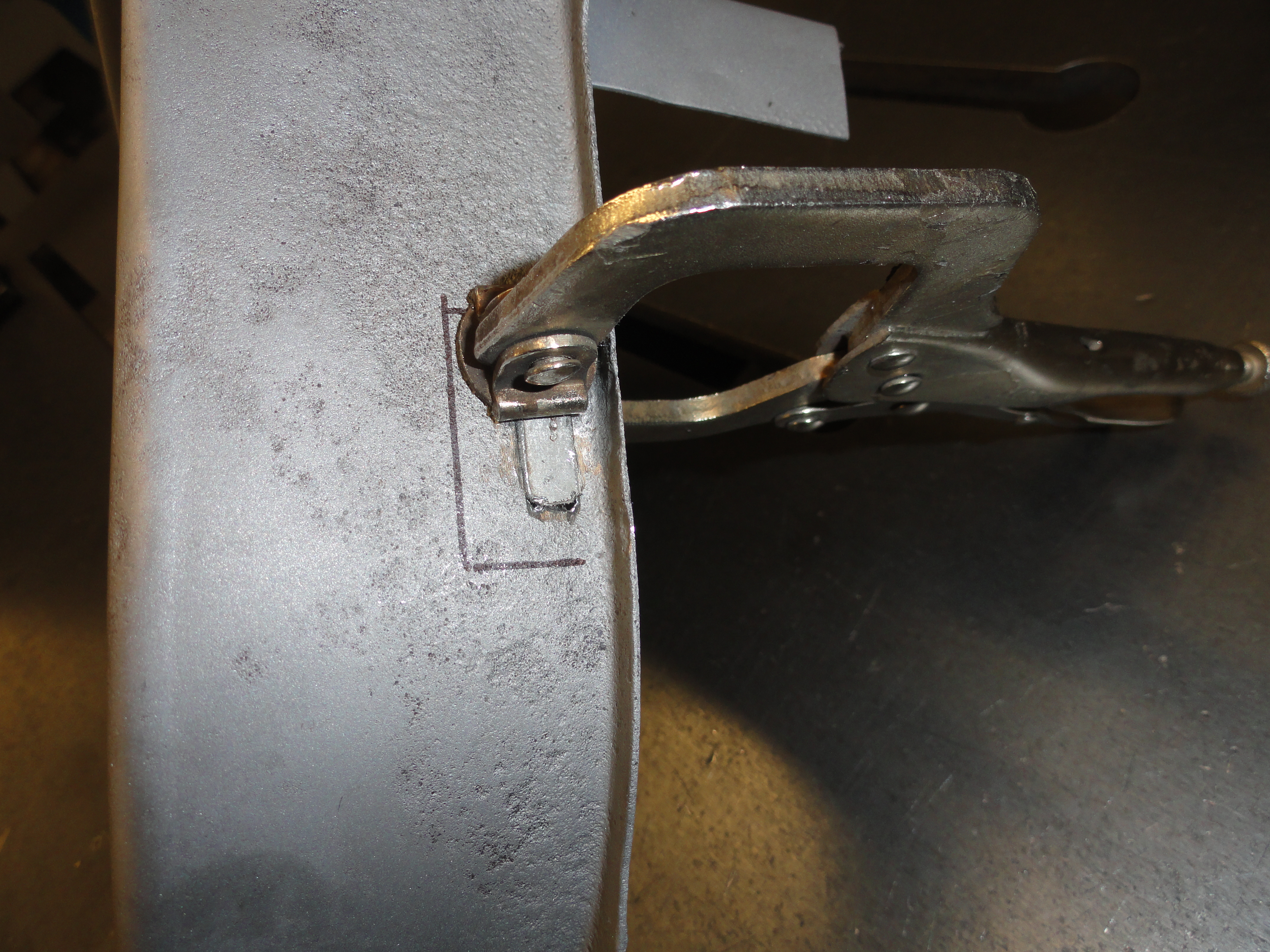
Repairs also included adding the defroster cable clamp that had broken off. This is the exact same one that is used on a carburetor, so I fashioned this piece so it could be welded on to the old broken mount. After all of the metal work is done, it is important to smooth out the rust pits and welded areas to get the pieces to come out perfect. To do this, I use a premium quality Filler, then sand everything down. This is a painstaking process but when completed, the metal will look just like it came out of the factory.
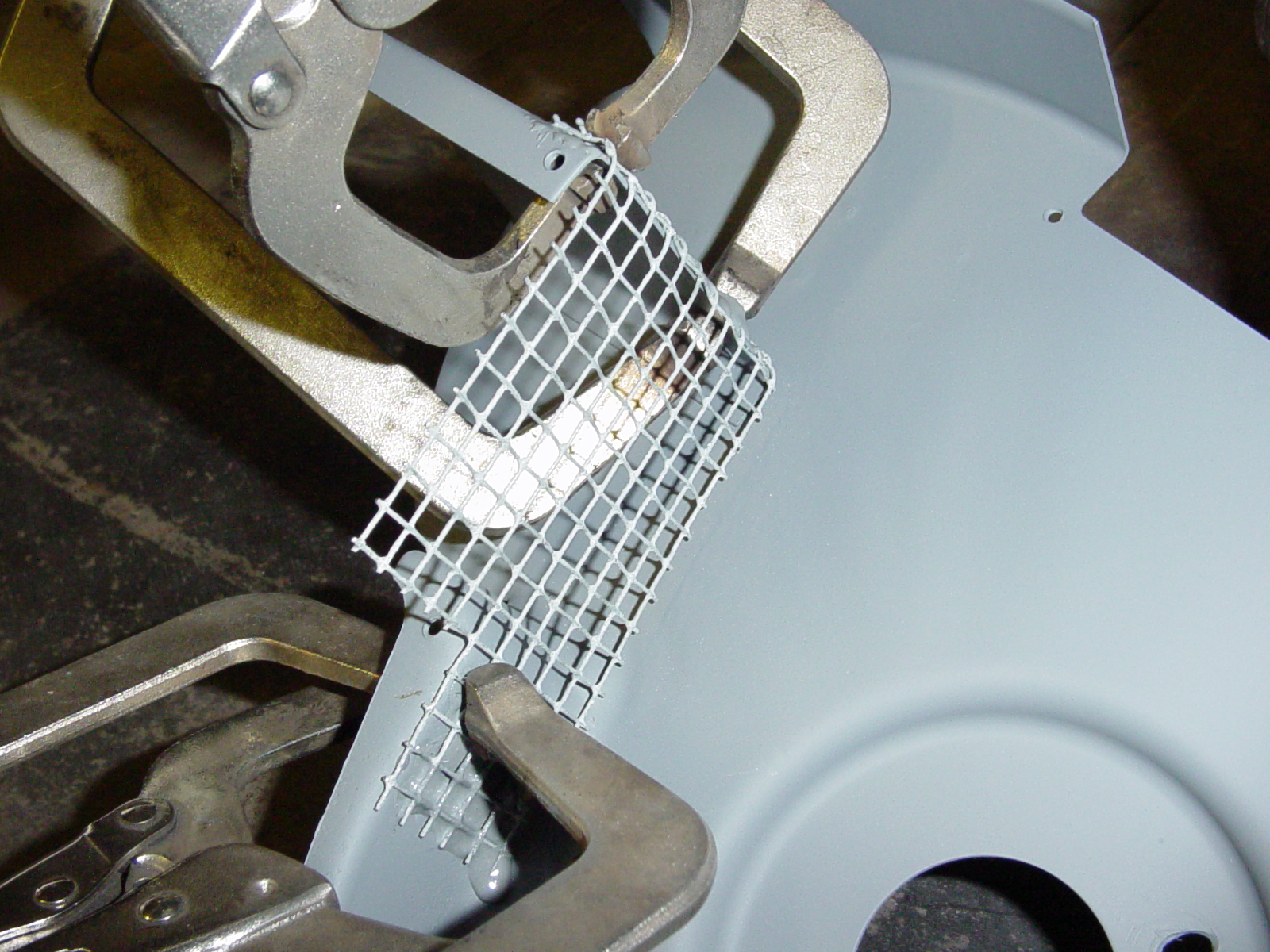
My heater had a missing screen. Since I have two and can see what was original, I discovered that 1/4" hardware cloth available at the local lumber yard was what they used originally. I just got a small piece and then used JBWeld to glue it down. It was originally tack welded into place, but that would be a little hard to do because most of the hardware cloth available is galvanized thus dangerous to weld. JBWeld works perfectly.
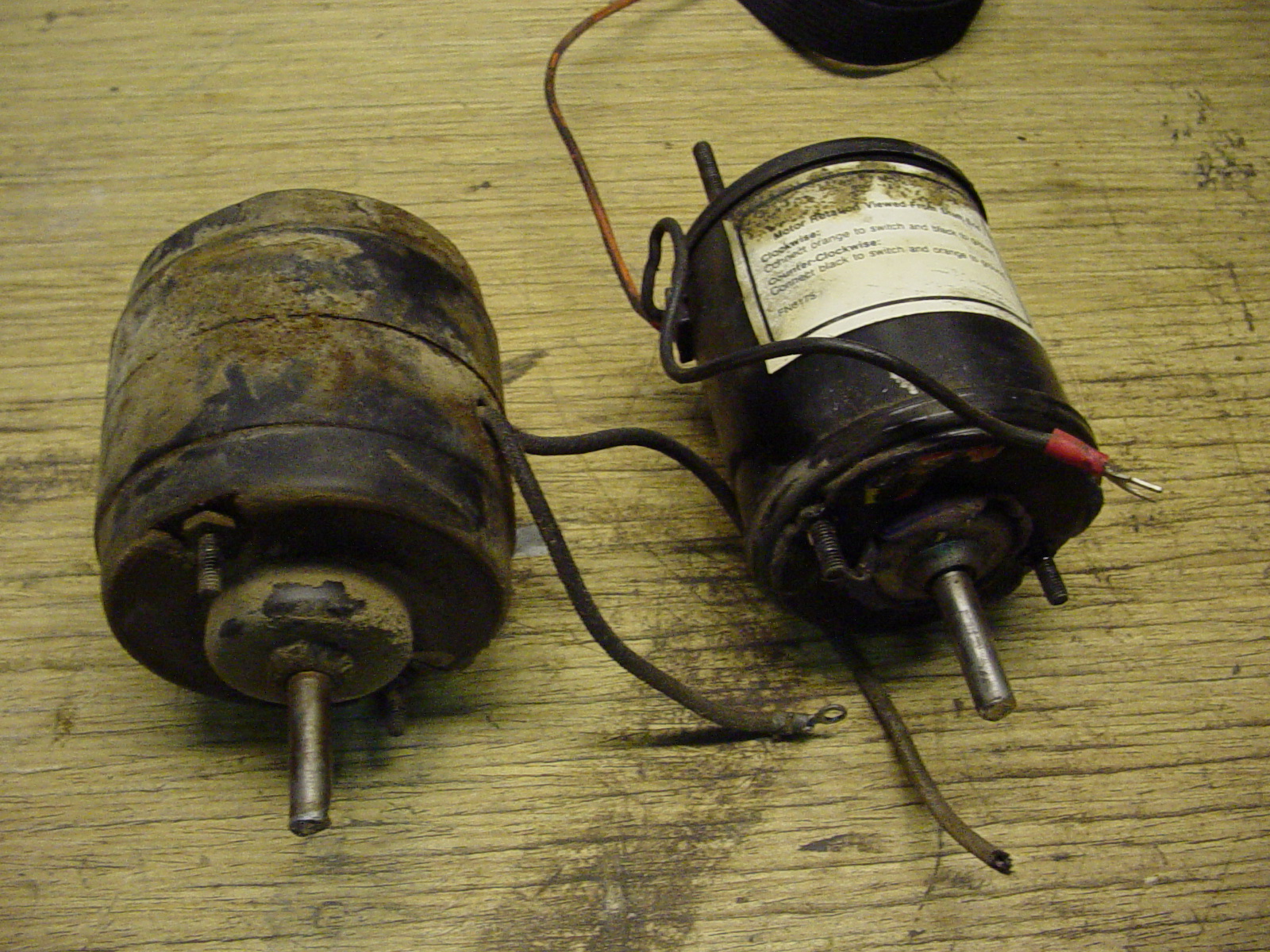
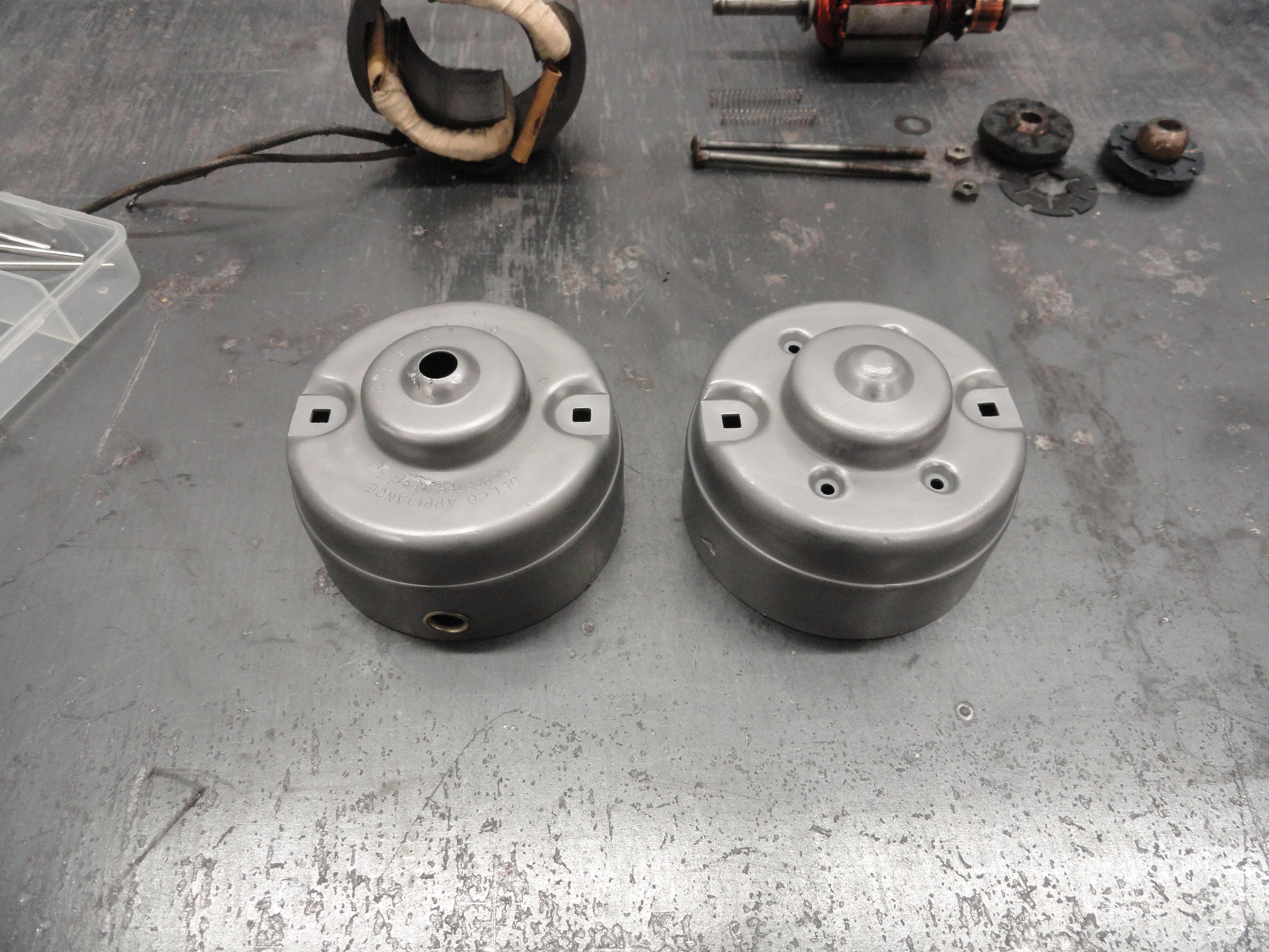
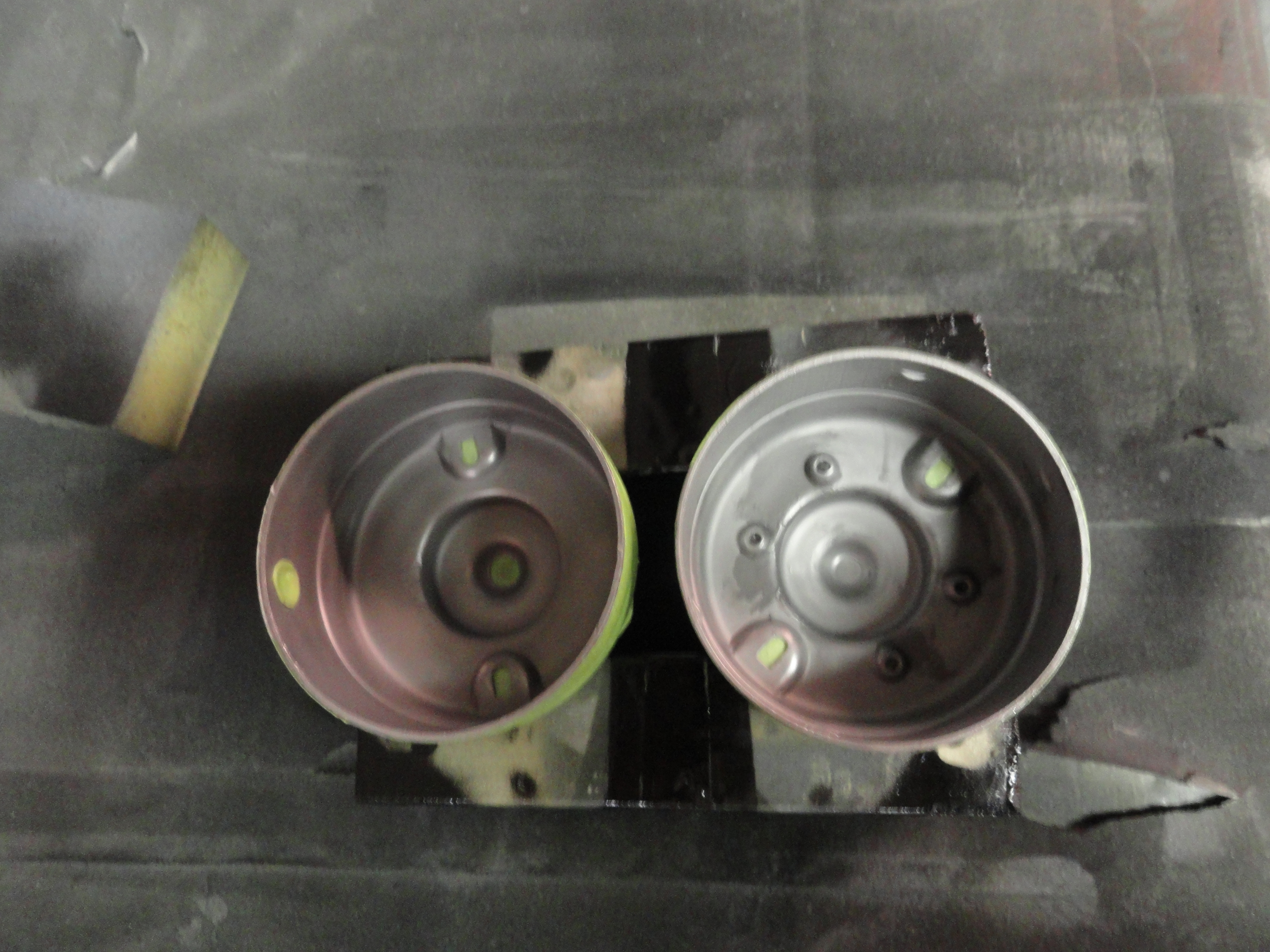
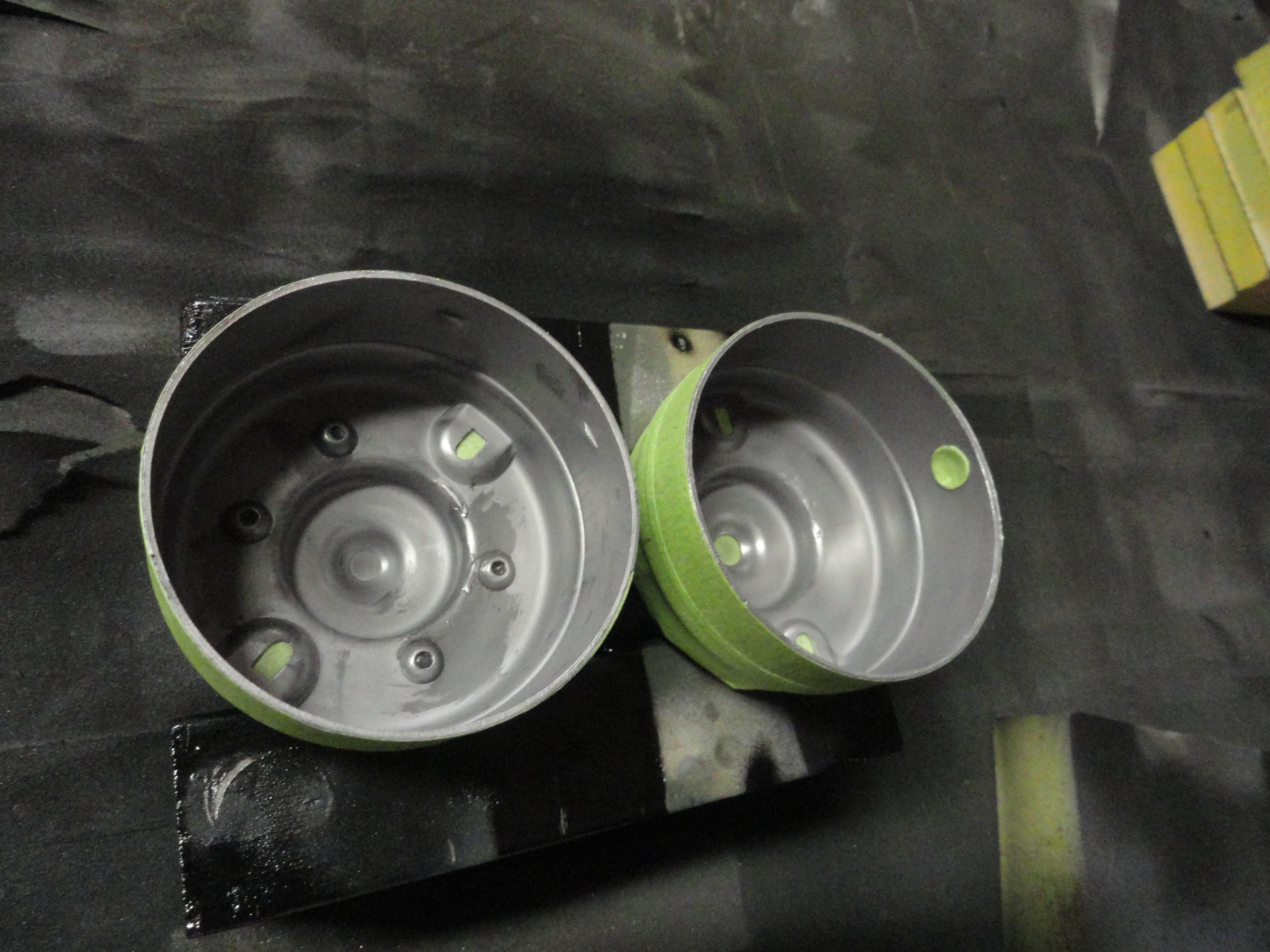
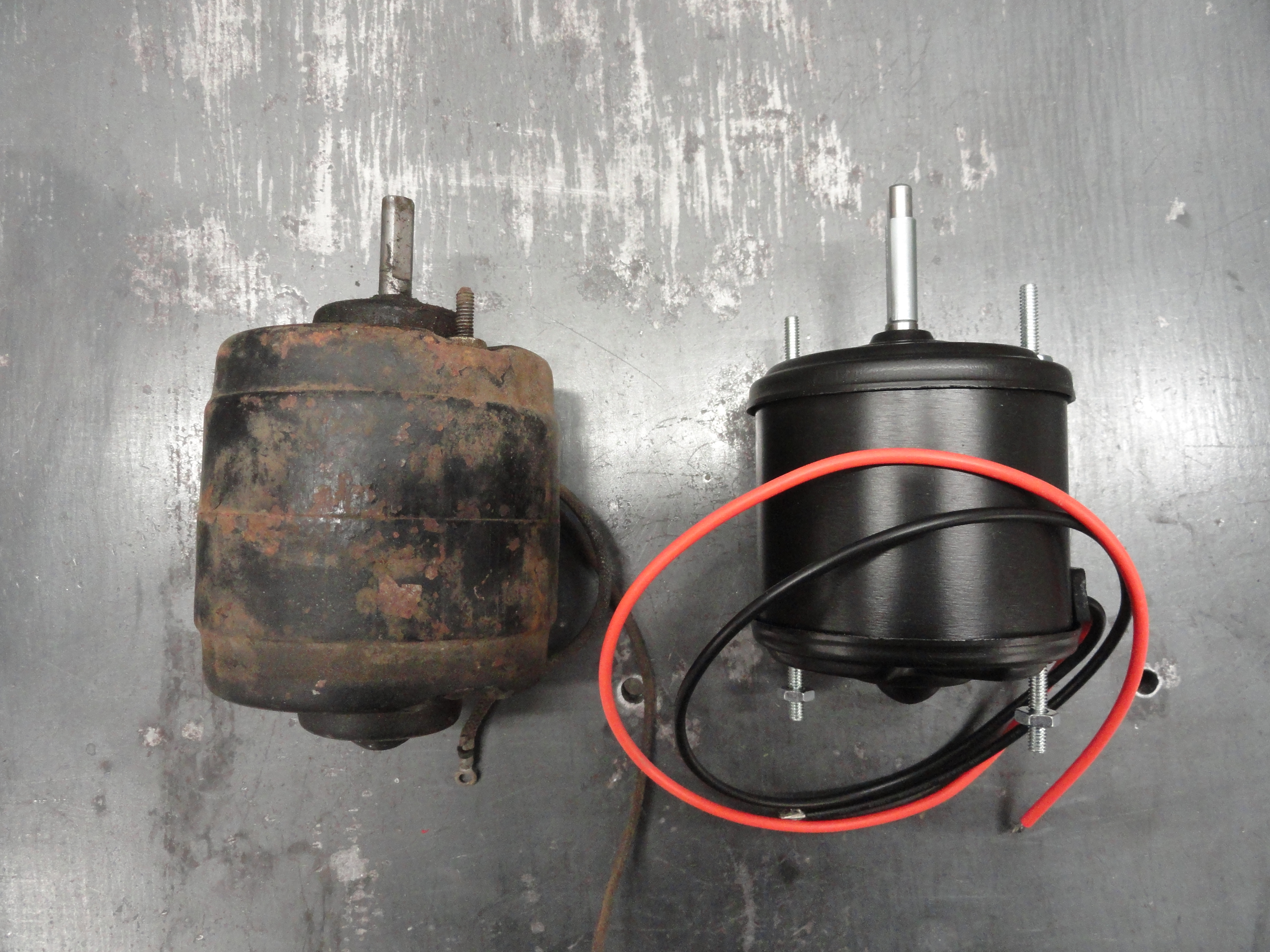
The one on the left is the 6 volt original and the one on the right is a 12 volt replacement. This difference would be noticeable under the hood thus unacceptable. It so happens that Chevs of the 40's sells a replacement 12 volt motor that is small enough to fit IN the 6 volt motor housing! It takes a little work to remove the 6 volt guts, but once you have done this, you have a perfectly original looking 12 volt motor. If the motor you get doesn't appear to fit (front to back), it may be because you are not done gutting the 6v motor. Clear inside the back of the motor housings is another small piece that's spot welded in. Remove that, and it should all make perfect sense. You will have to elongate the mounting holes and ensure all air holes are not obstructed, but it turned out to be easier than I had expected. More...
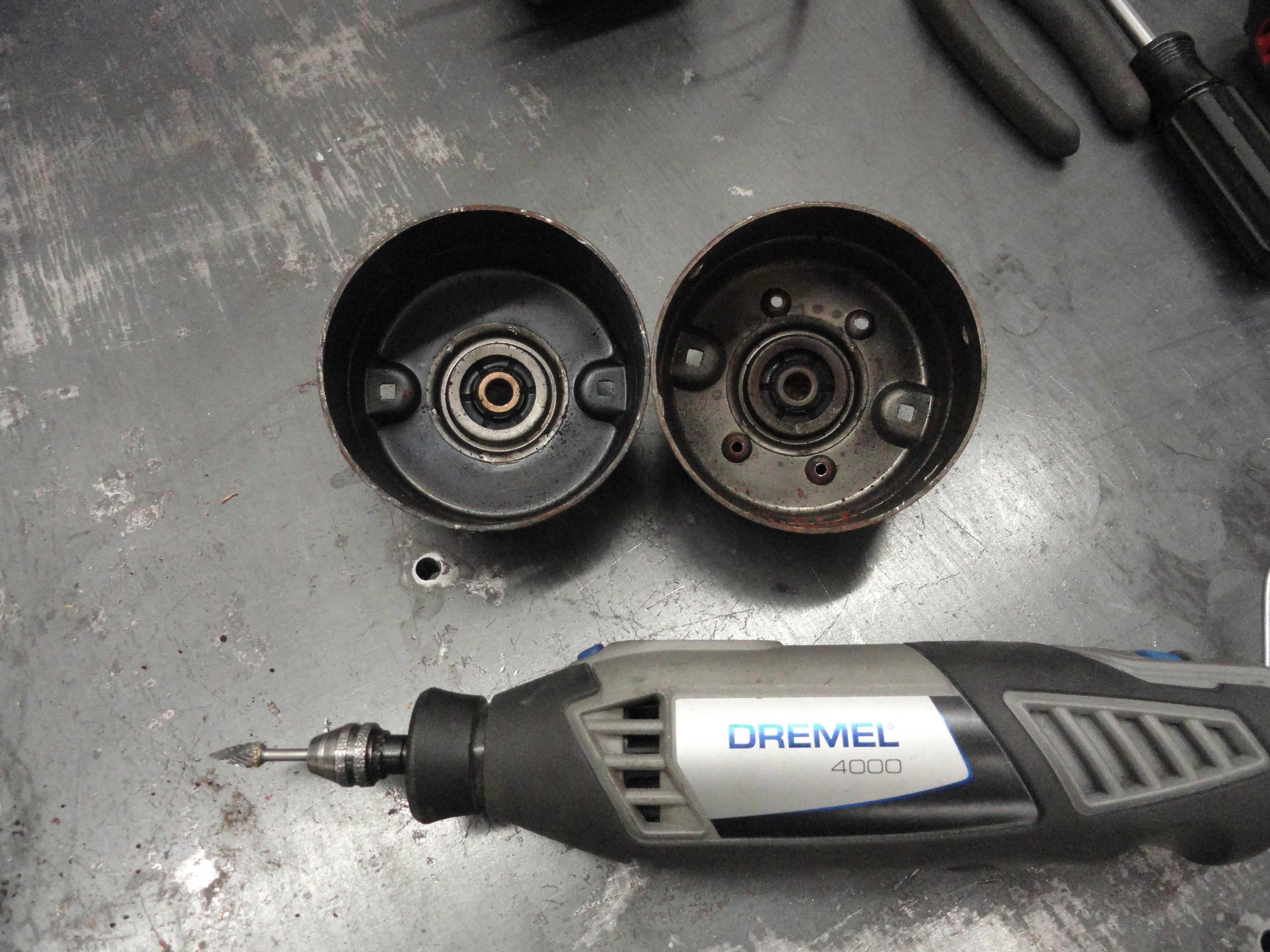
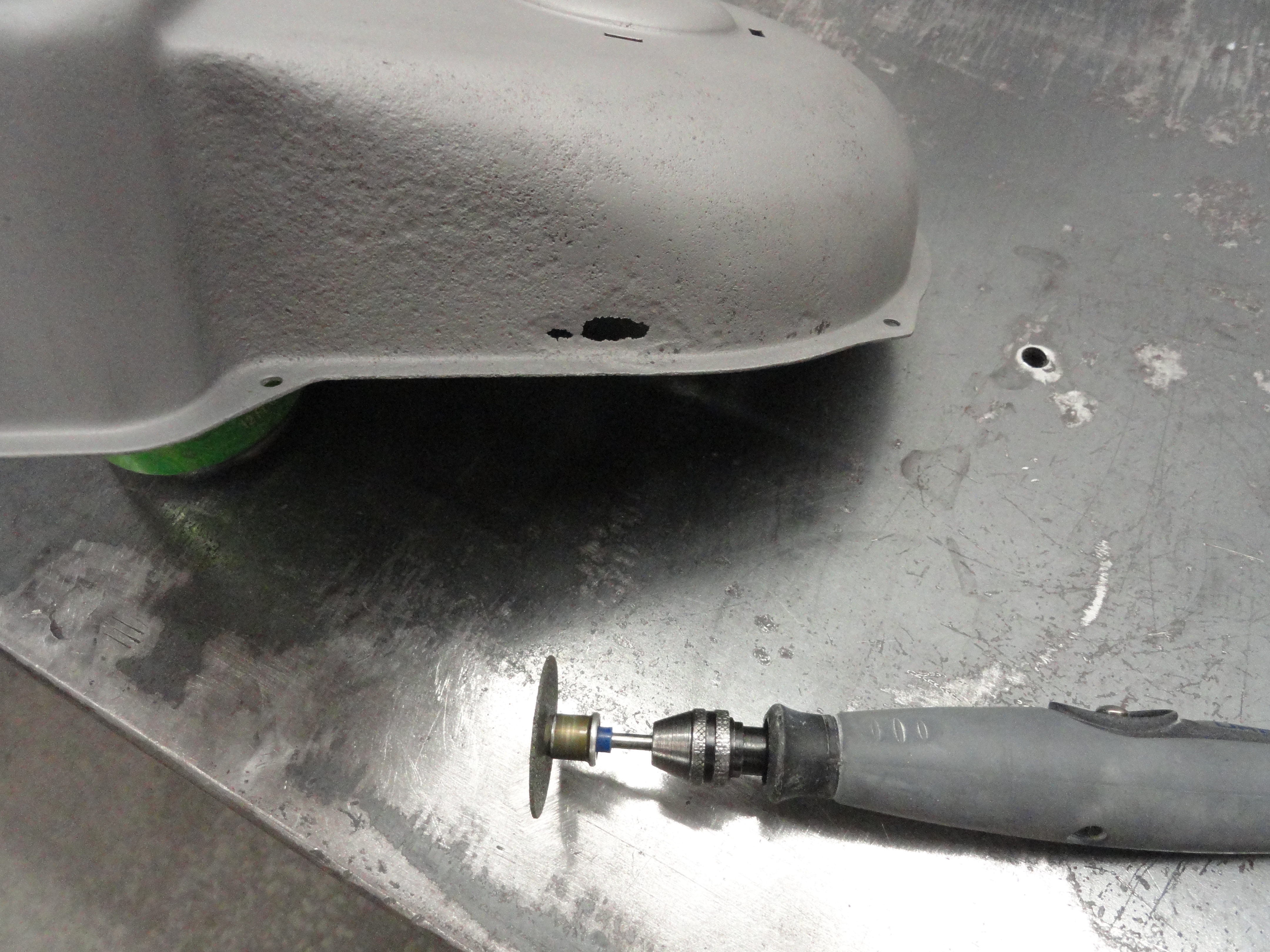
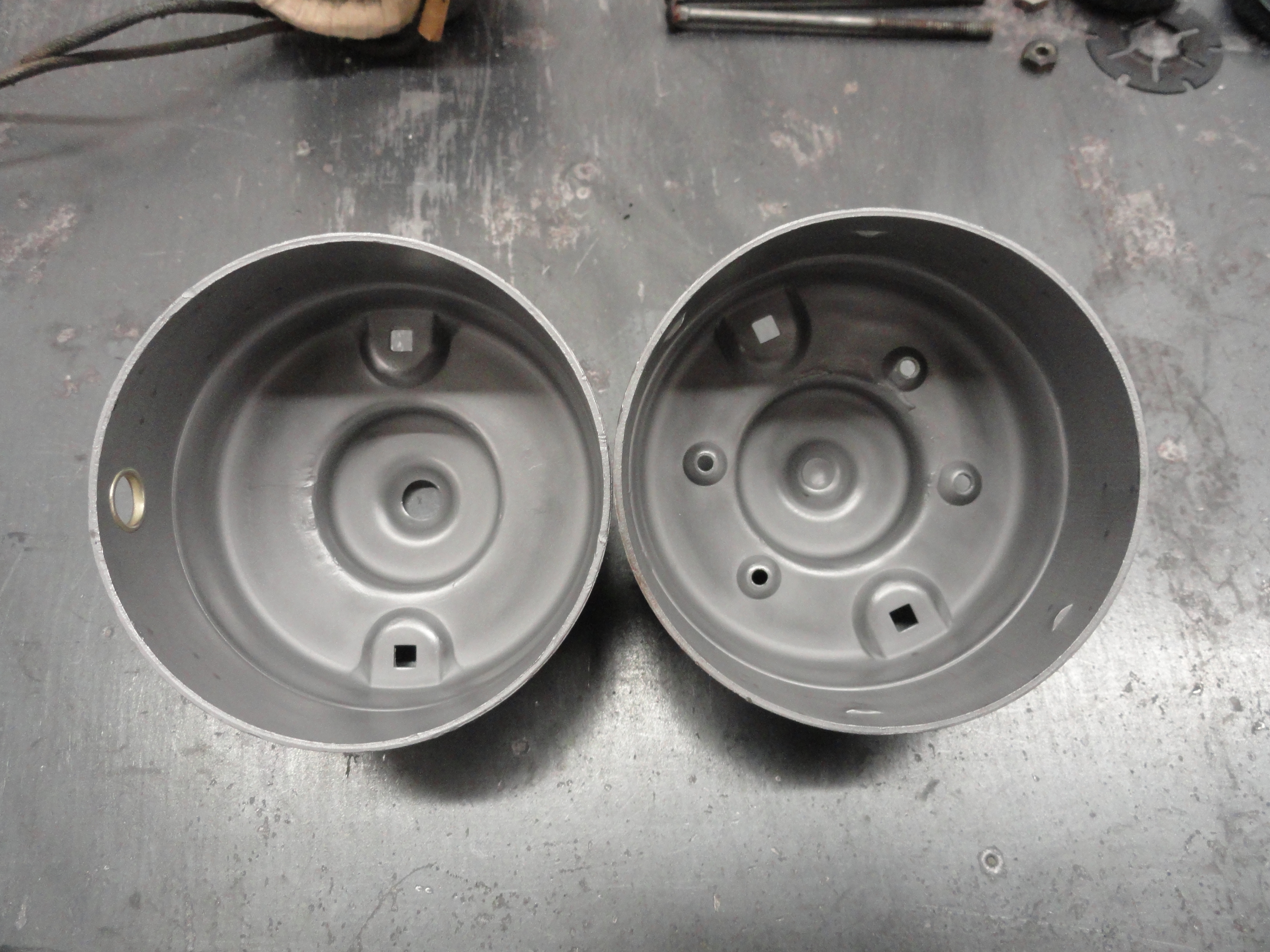
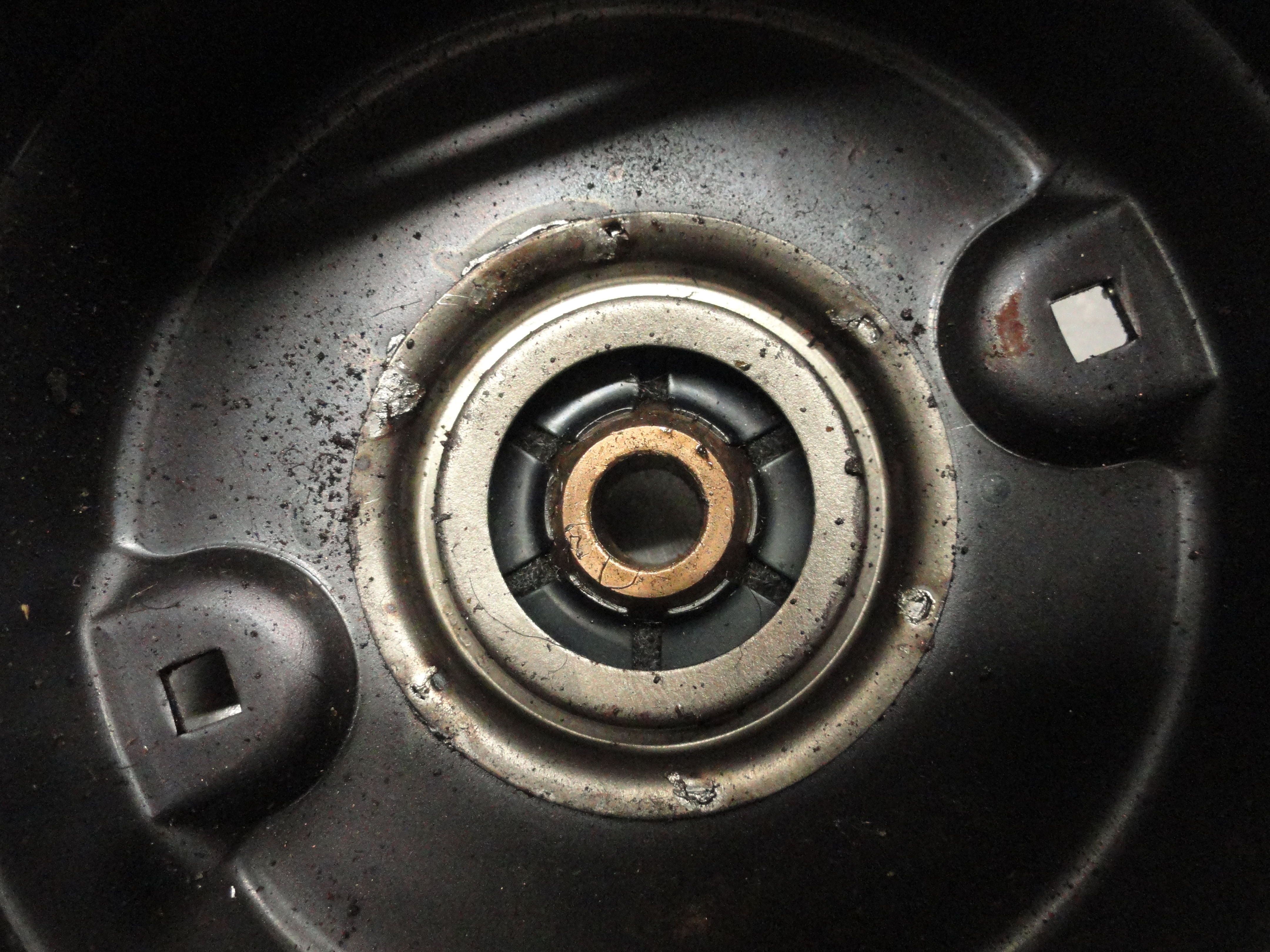
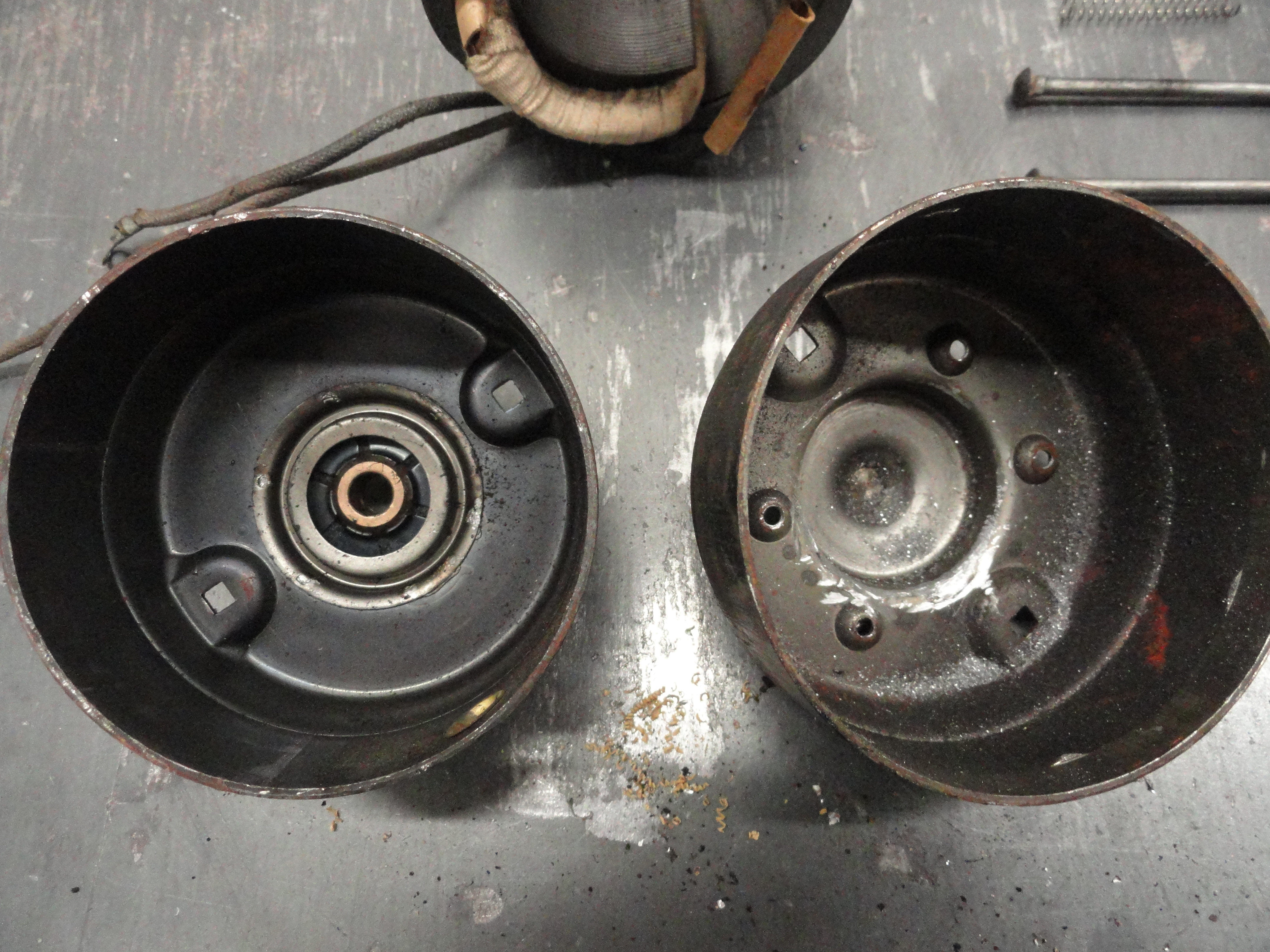
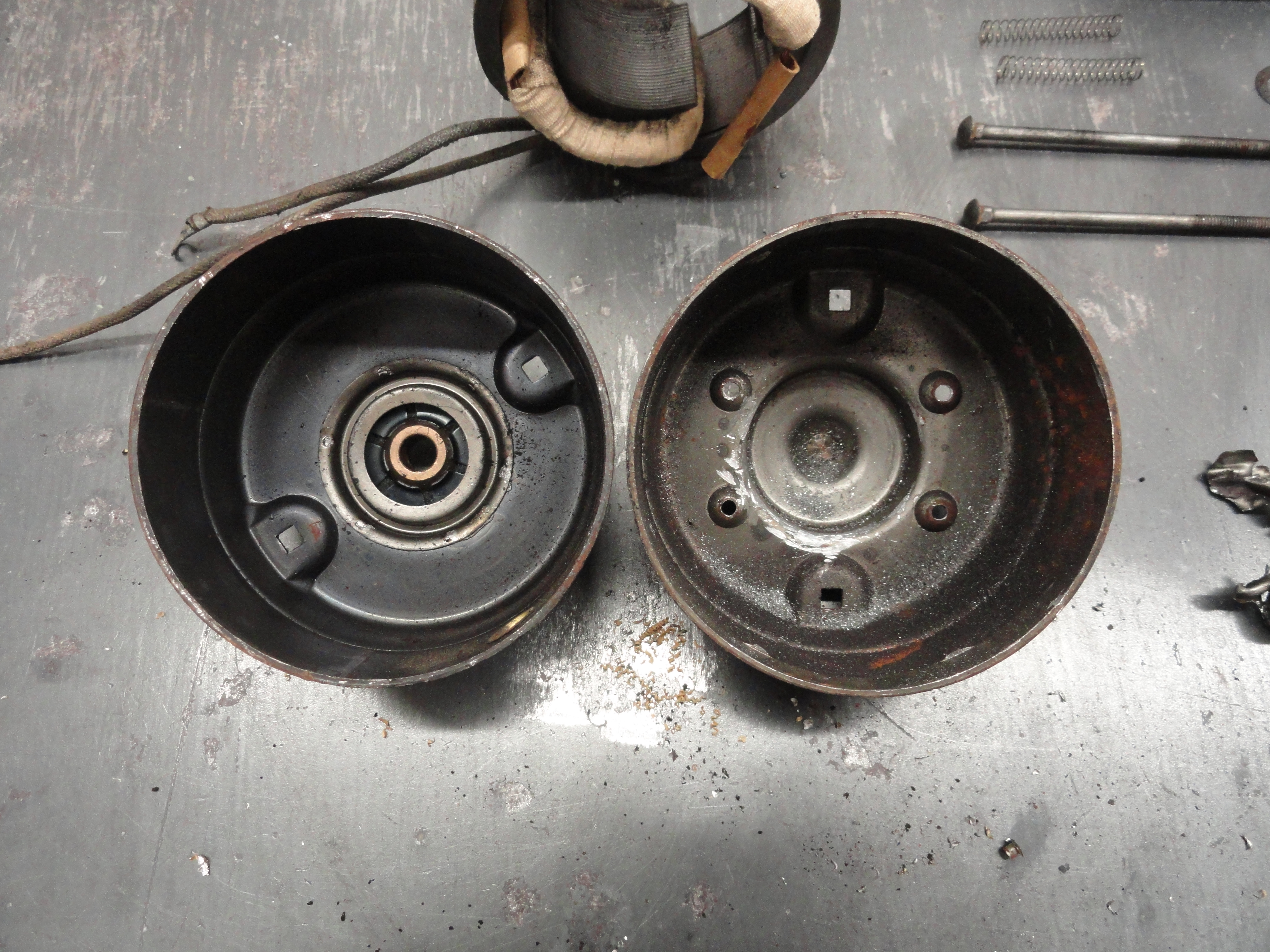
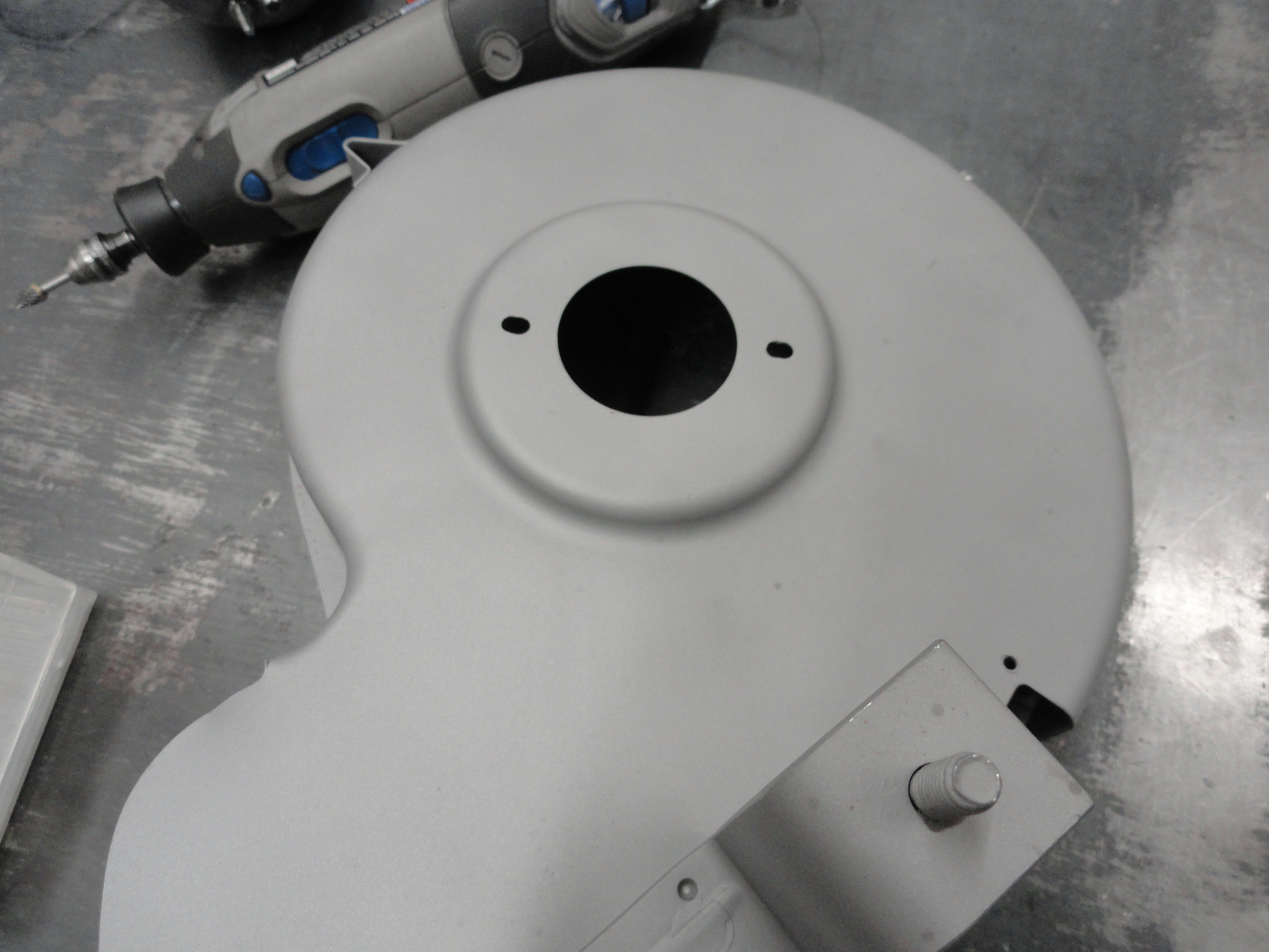
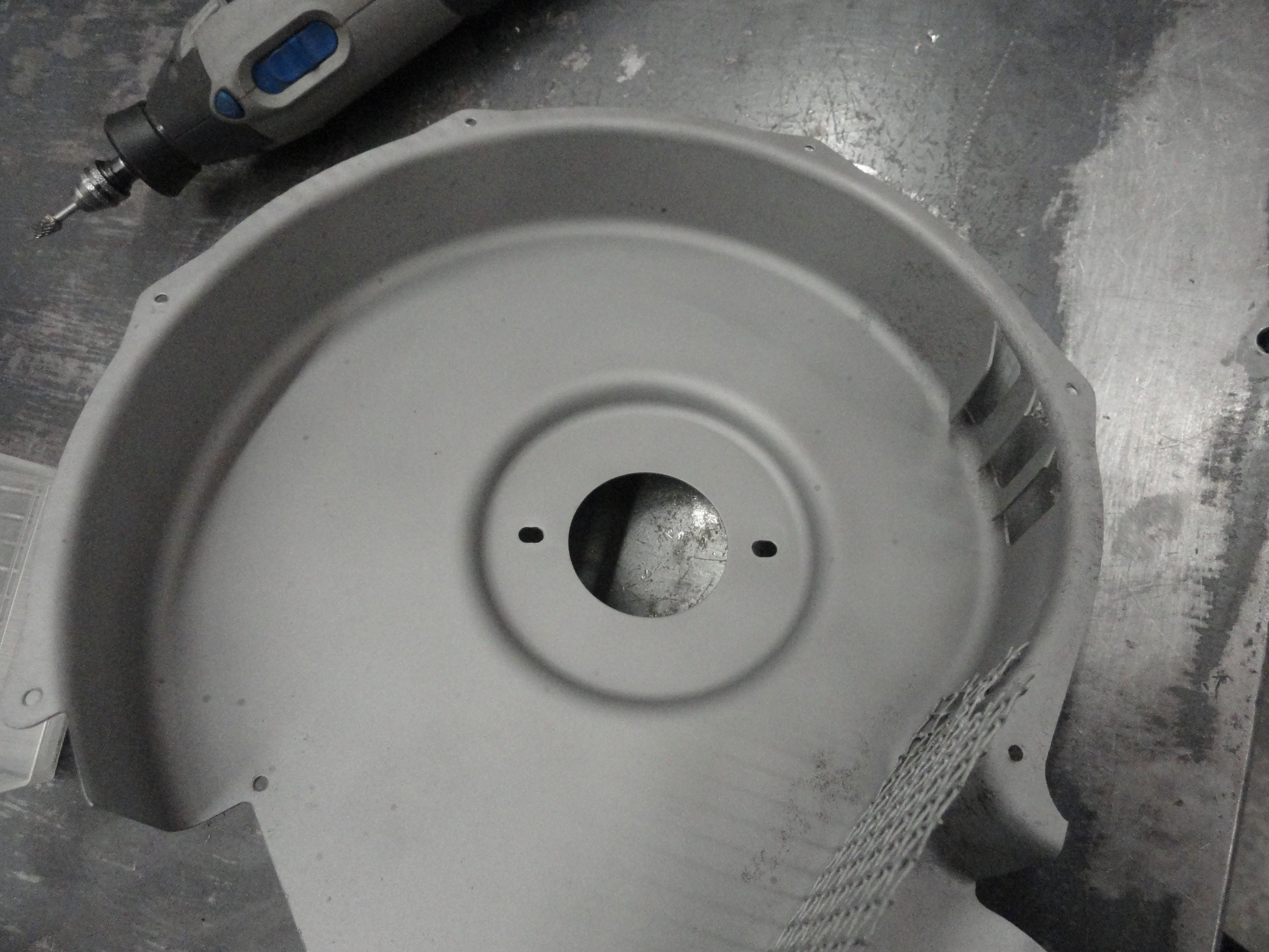
I get asked all the time about how I went about doing this. The key thing is to get all of the guts out of the 6 volt case. On each end there is a round molded metal piece that is spot welded into the case. You will notice the spot welds in the pictures. With a Dremel tool or whatever you have to remove spot welds, carefully remove the spot welds taking care to not go through both pieces of metal. I have a hard time getting these out too, but once one of the spot welds is loose, you can use a pair of pliers to get the piece out.
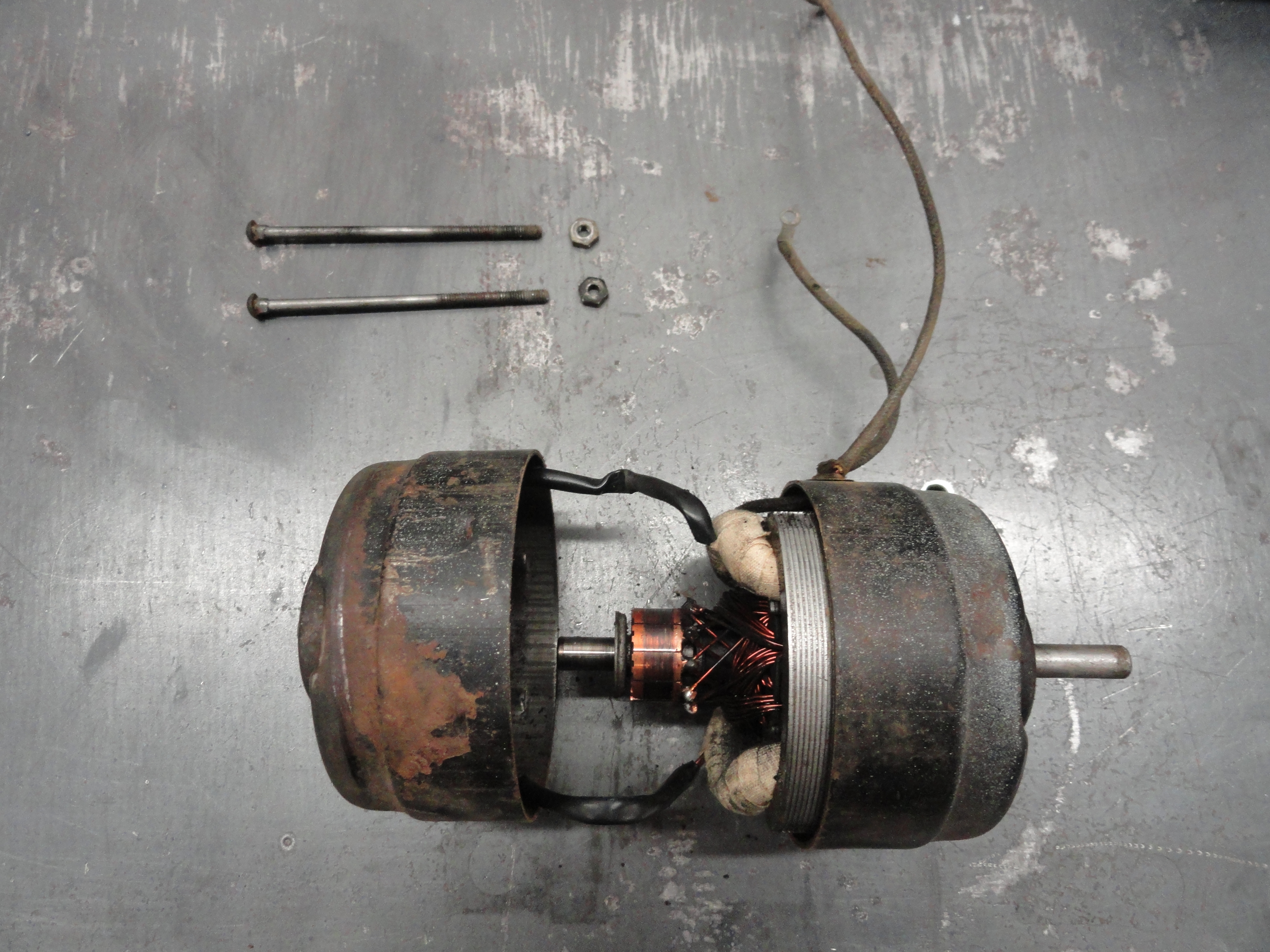

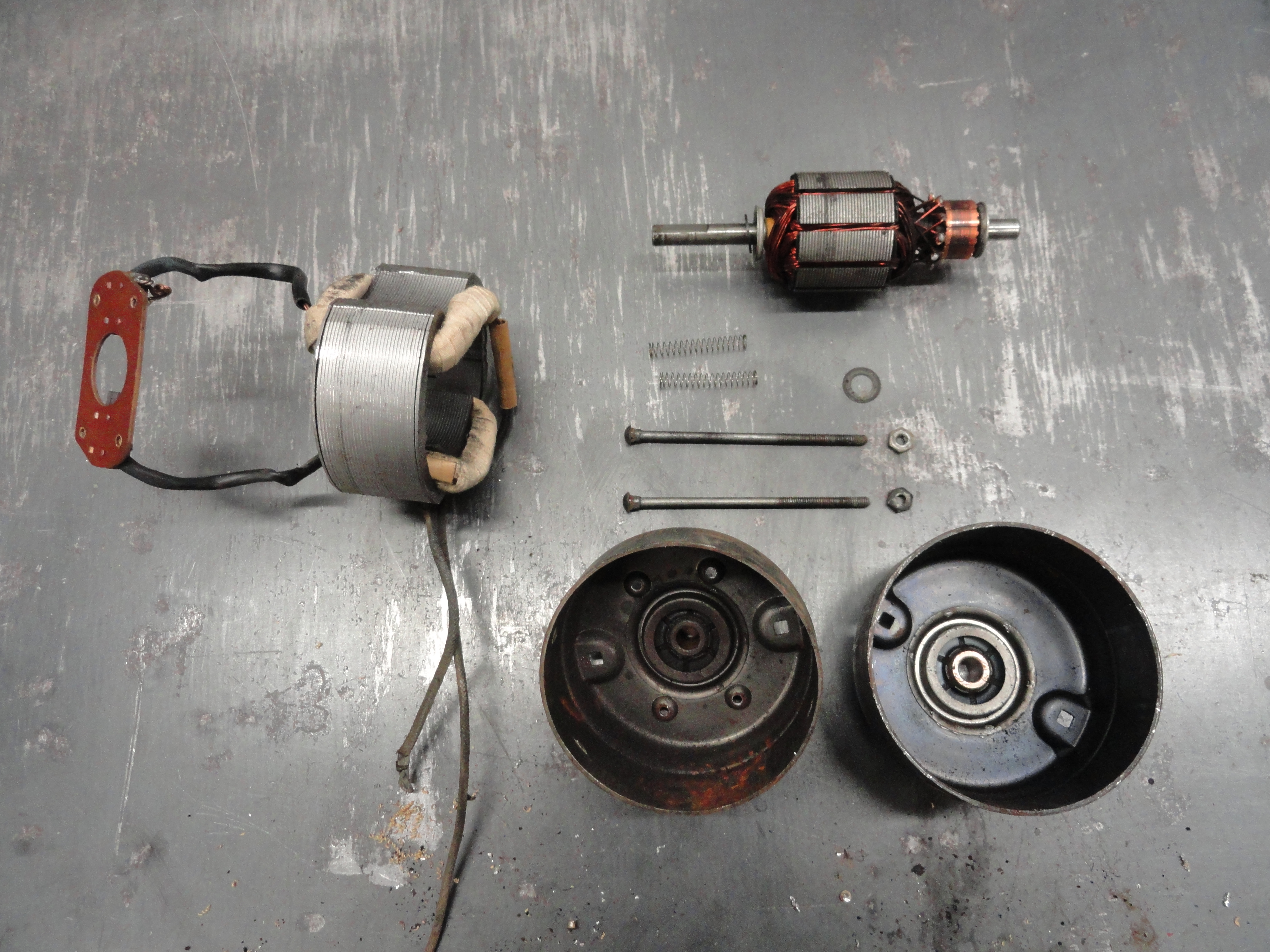
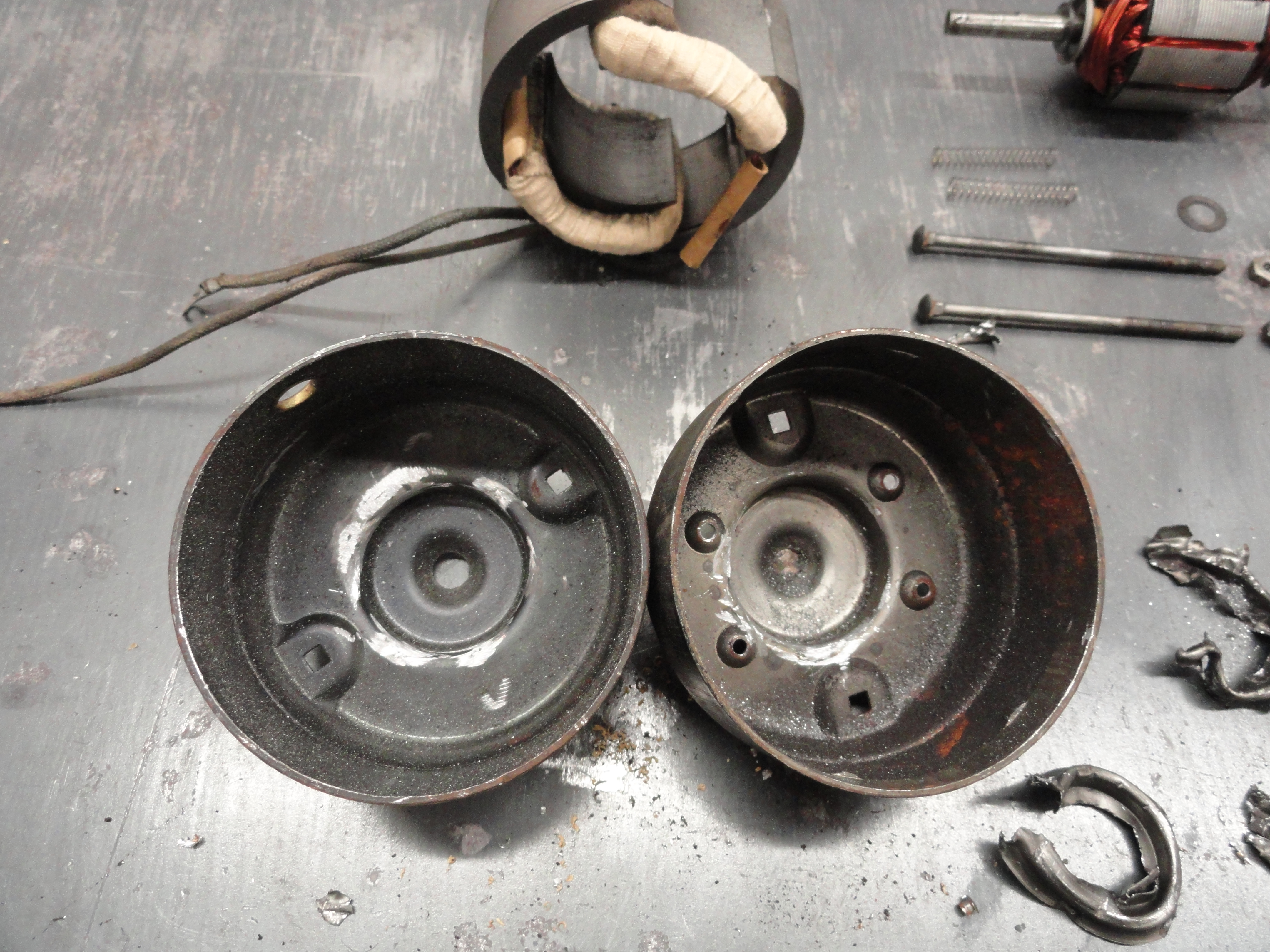
The 6 volt motor disassembles pretty easily. I use a 1/8" drill bit to drill out the rivets holding the brush block to the case, then tap the outside core out with a screwdriver lightly tapping all the way around until it pops out. We will use no packing or anything to keep our 12 volt motor centered, nor will we remove anything from the 12 volt motor. The motor just like it comes out of the box will go right into our new case. I sandblast the case parts inside and out then using a Dremel Tool with a light wire brush, clean everything. This shines up the brass and metal quite nicely. Once everything is complete, I will take it apart for the last time and clean the case inside and out with PPG's DX330, then primer and paint inside and out to prevent rust. Don't forget, this is just a shell. The motor inside is 100% protected against any damage or anything since it is sealed from the factory.

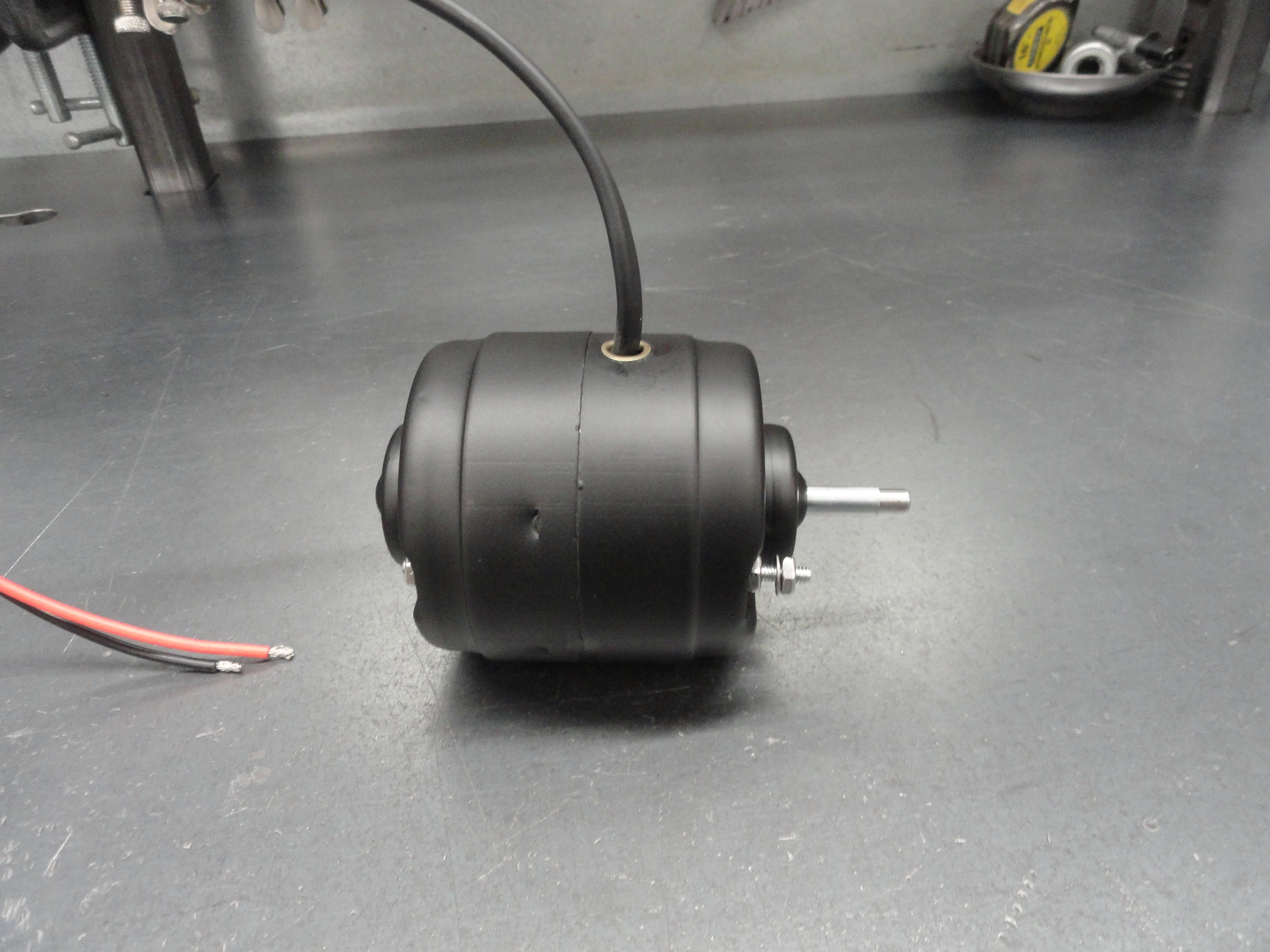
The 12 volt motor shown here is a standard 12v replacement motor available at any of our truck vendors. It is THE best motor
for this project. Siemens started making the PM354 awhile back, now it's VDO. They are both maximum 3500 RPM motors which is
perfect for our application.
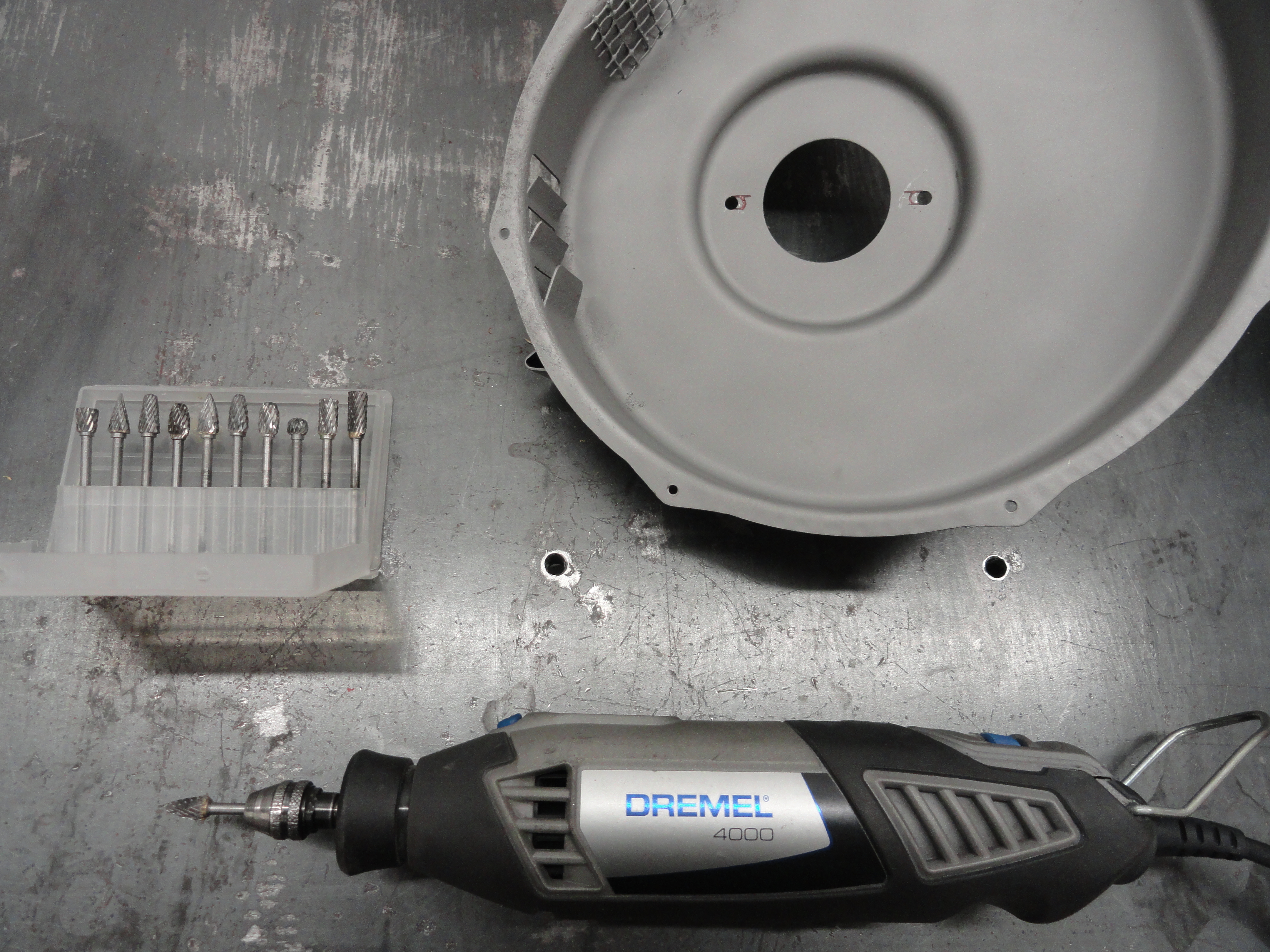
The only modification we have to do for this setup is to elongate 6 holes. Four in the motor casing and 2 in the Harrison housing
assembly to attach the motor. Elongating the holes will not change anything and it will be a nice snug fit. I use a Dremel Tool
for this process.
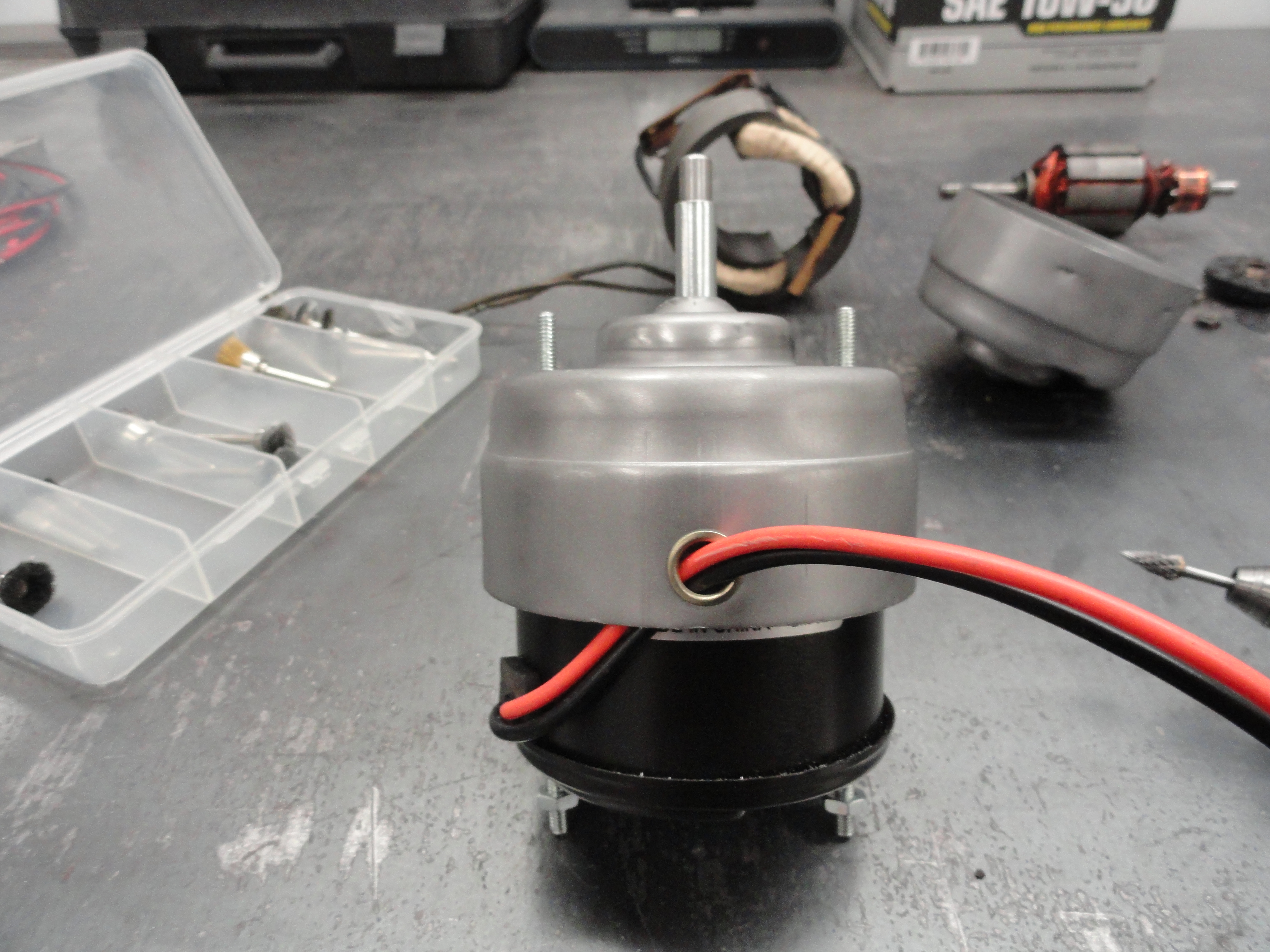
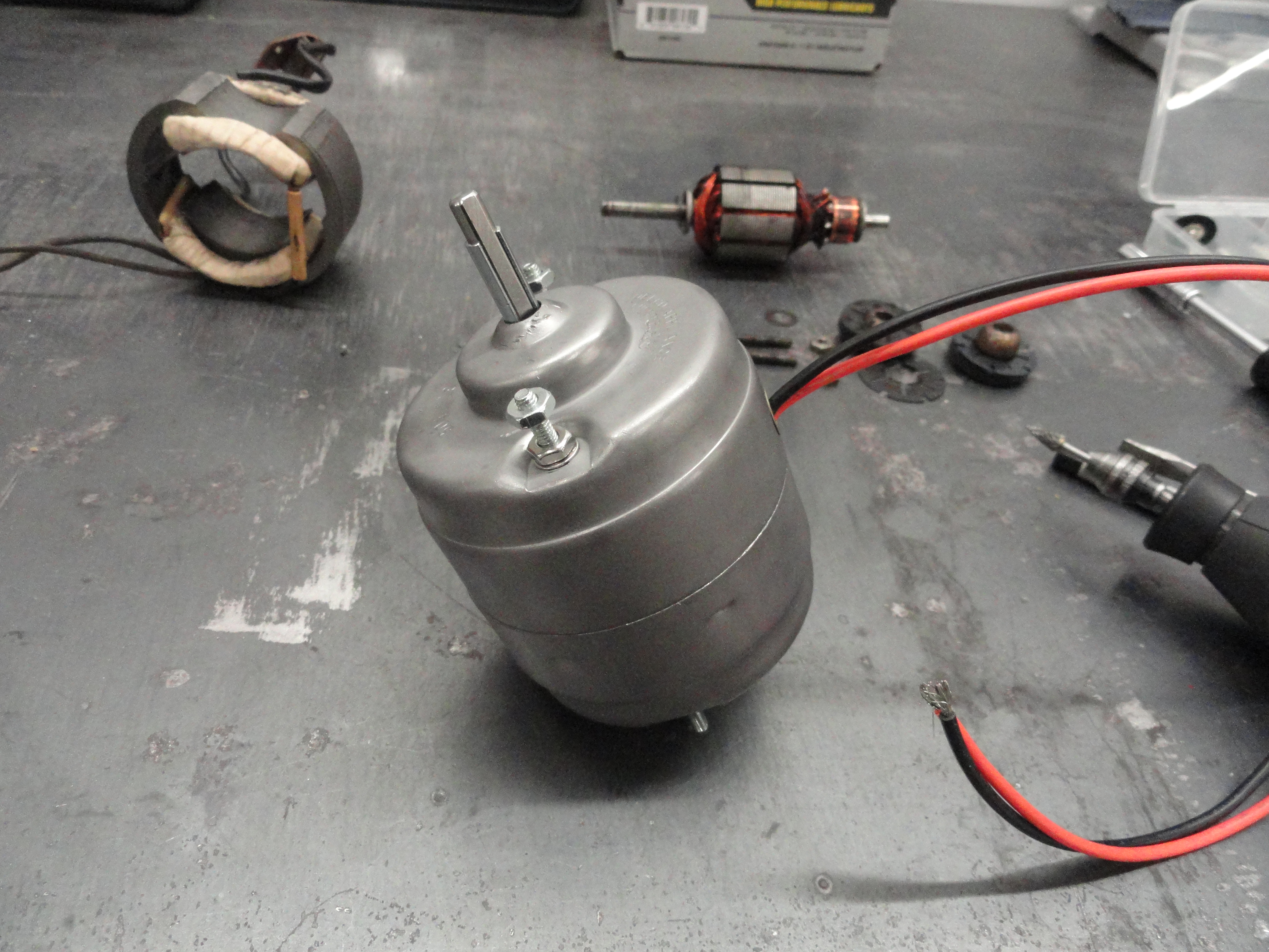
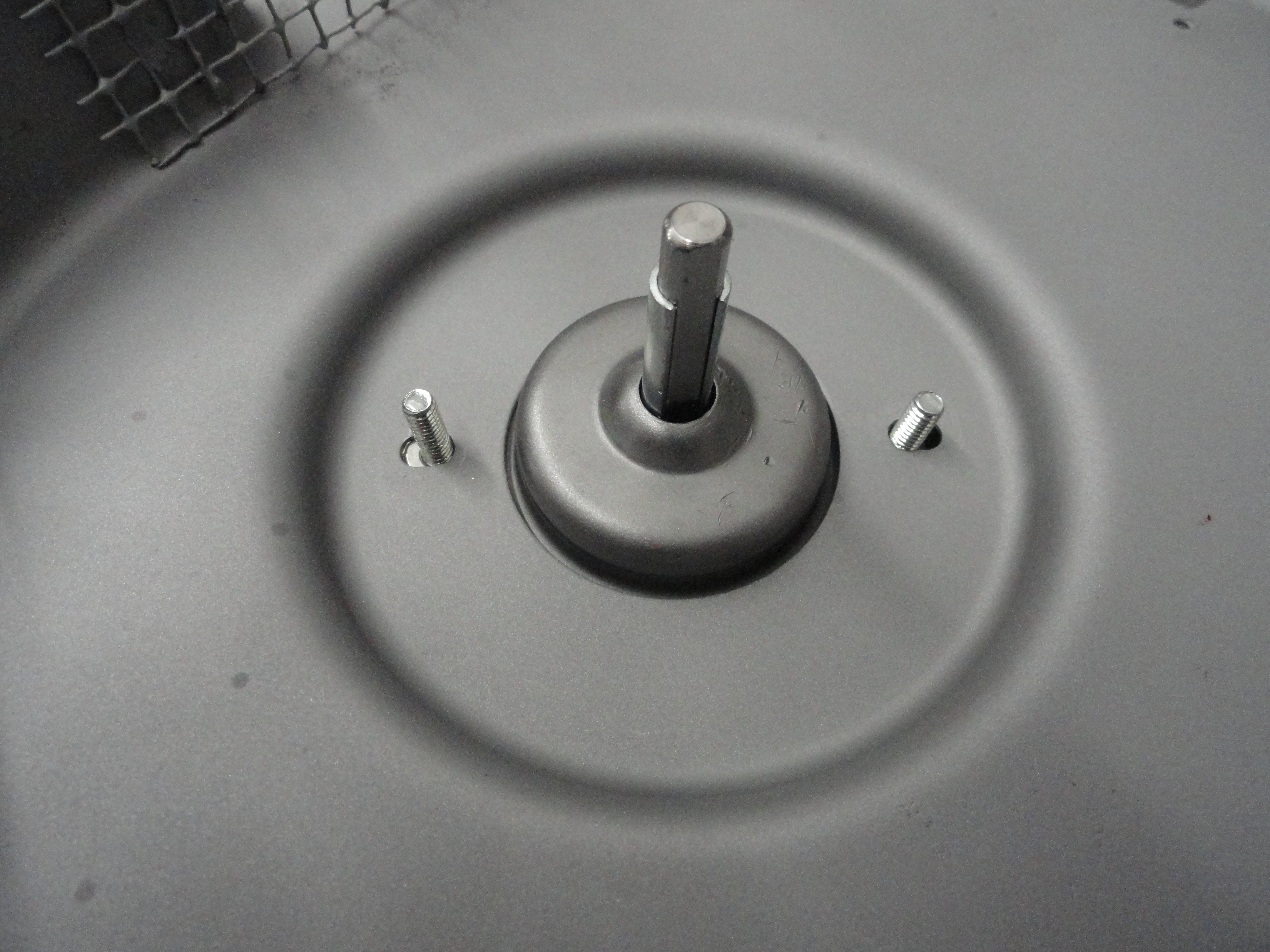
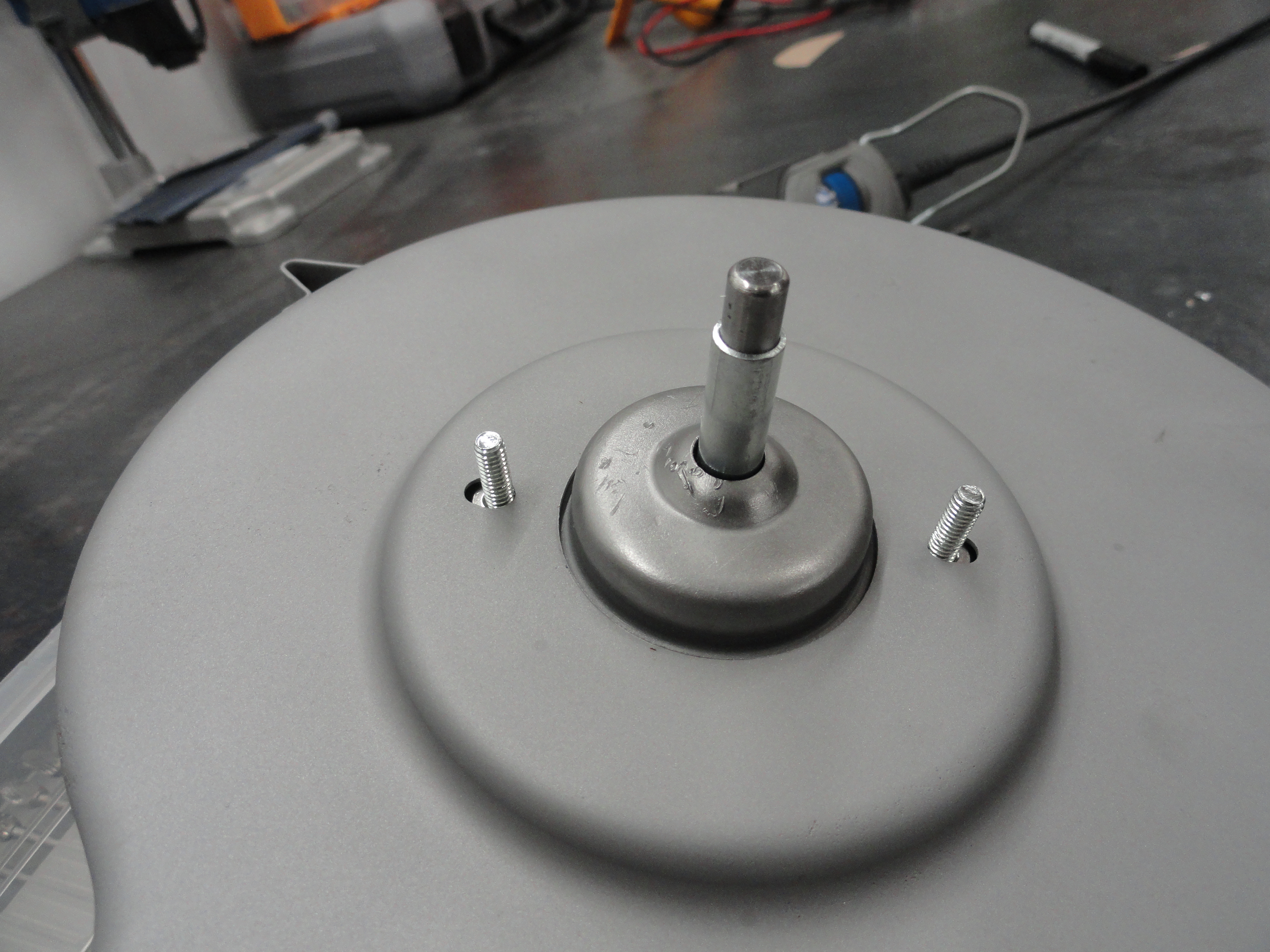
As you can see, the motor just sits right inside the case as if it belongs there! The motor shaft is centered in the cases shaft hole and nothing can move around because it is bolted in from the bottom and from the top. Aligning the top and bottom halves are no problem whatsoever. After this step, I will put a piece of 1/4" shrink tubing about 10 inches long over the wires with the shrink tubing going inside the case as far as it will go, then add an 8-32 round terminal to the Negative lead for grounding to the case and a splice on the Positive lead for adding more length later.

The only modification to your Harrison Heater is the two mounting holes for the motor need to be elongated to accommodate the narrower bolt pattern. This is easily done with a Dremel Tool with a Carbide bit. The nice part about this modification is that if you wanted to put a 6 volt motor back in, there is no reason you can't. I have done this modification three times to this date and I am amazed each time at how easy it is to upgrade your Heater in this way. The other major advantage is, you are not doing what everyone else does. You are not converting power to heat in order to reduce the voltage of your motor!

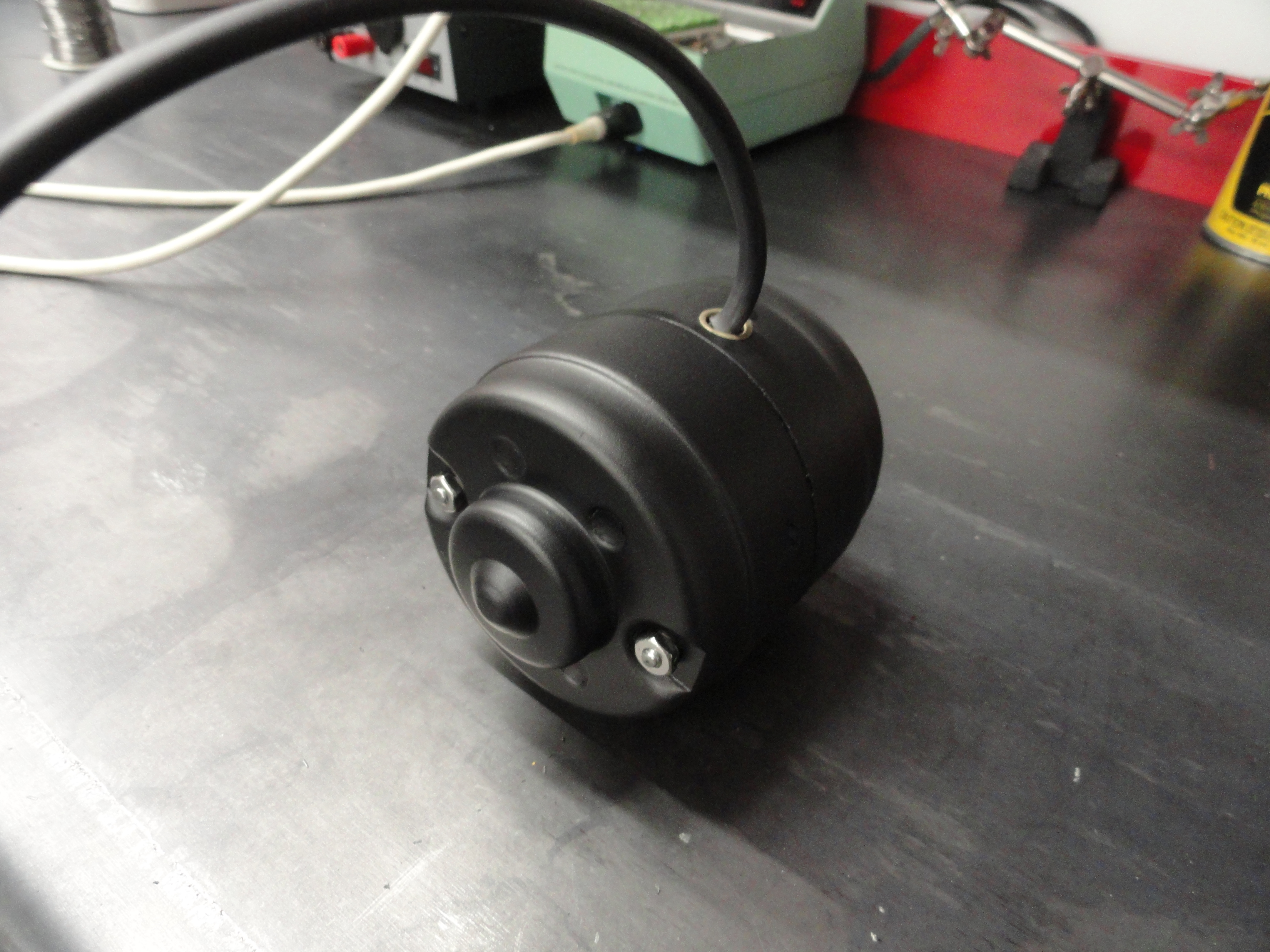
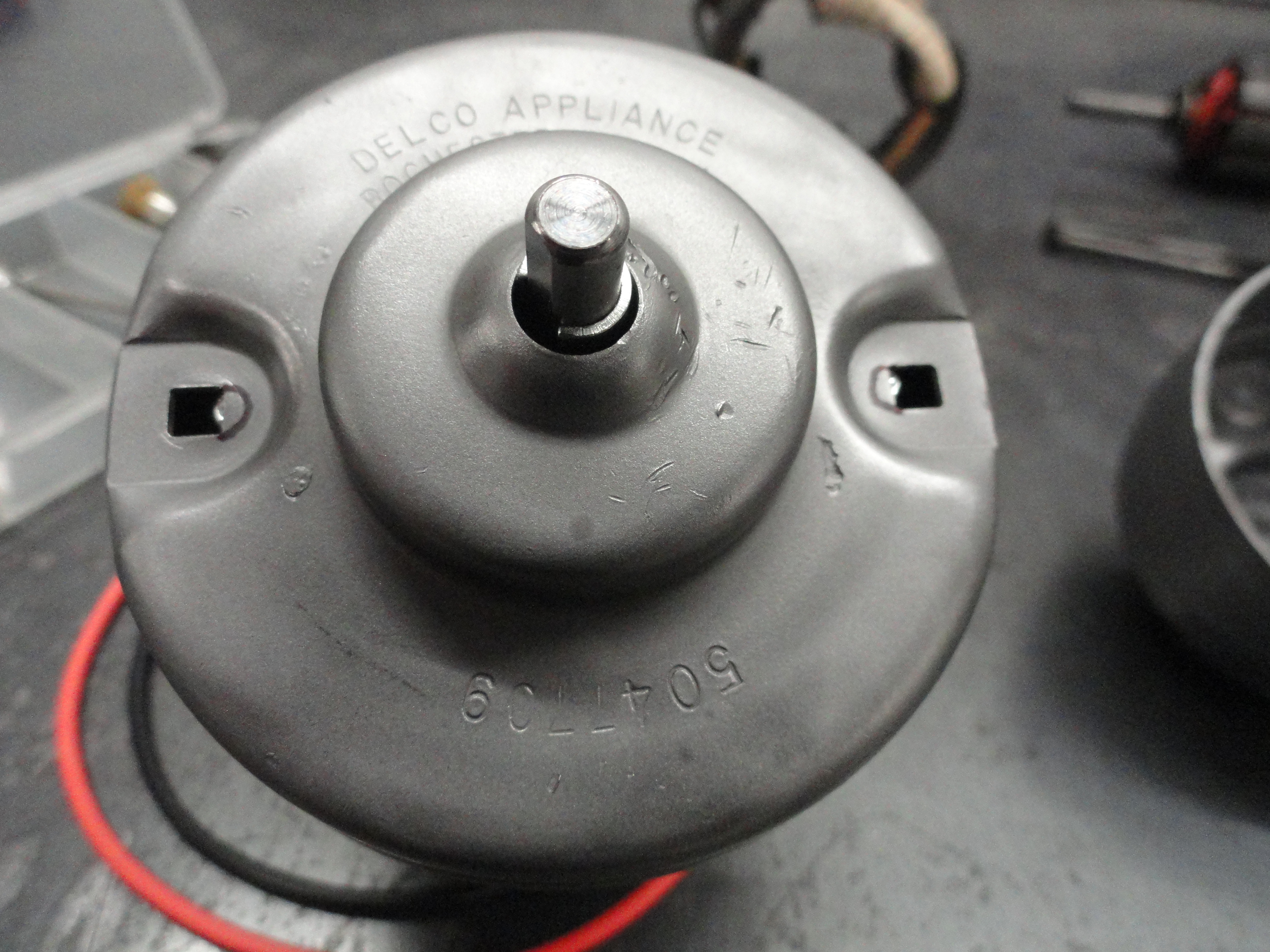
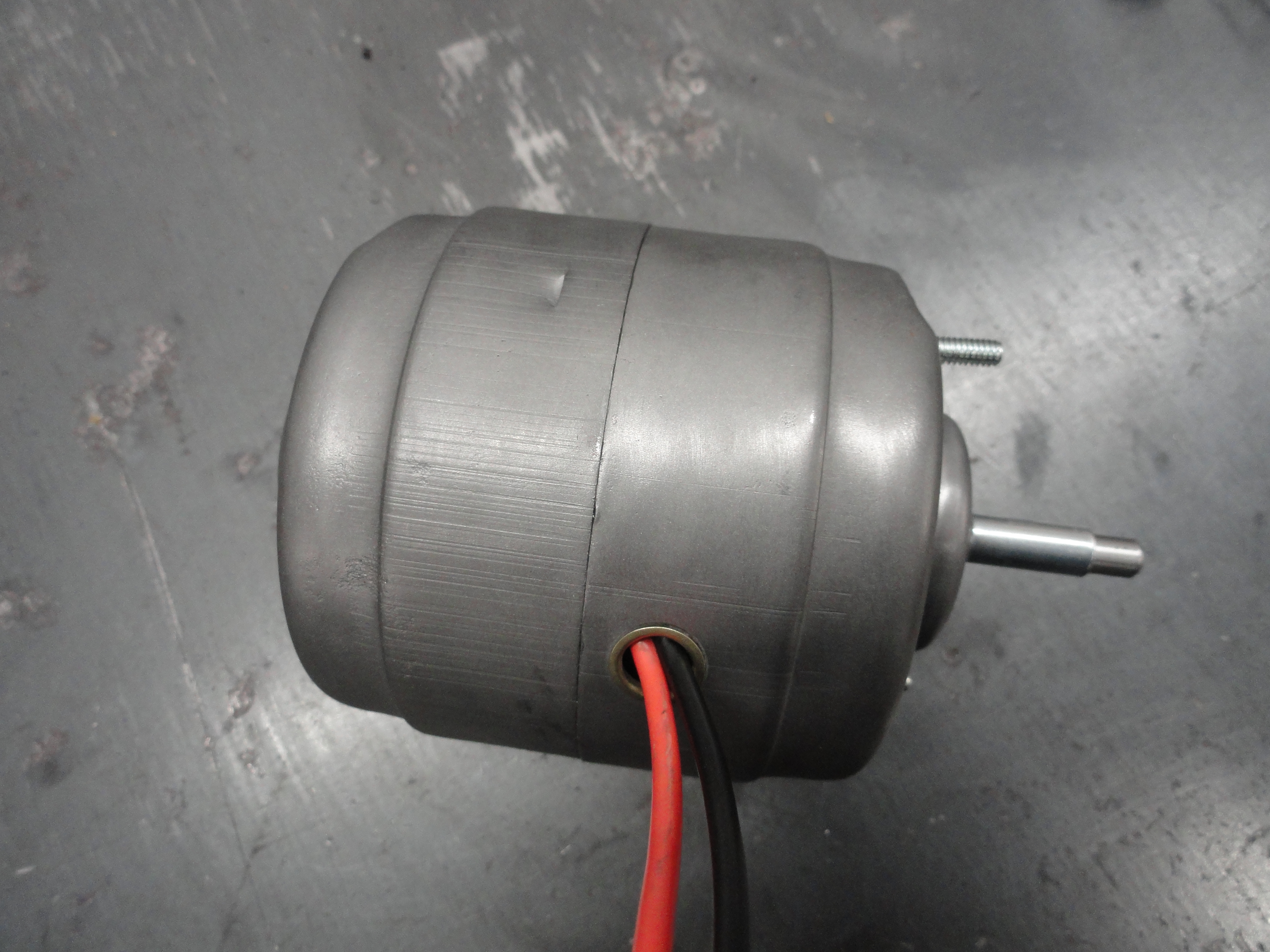
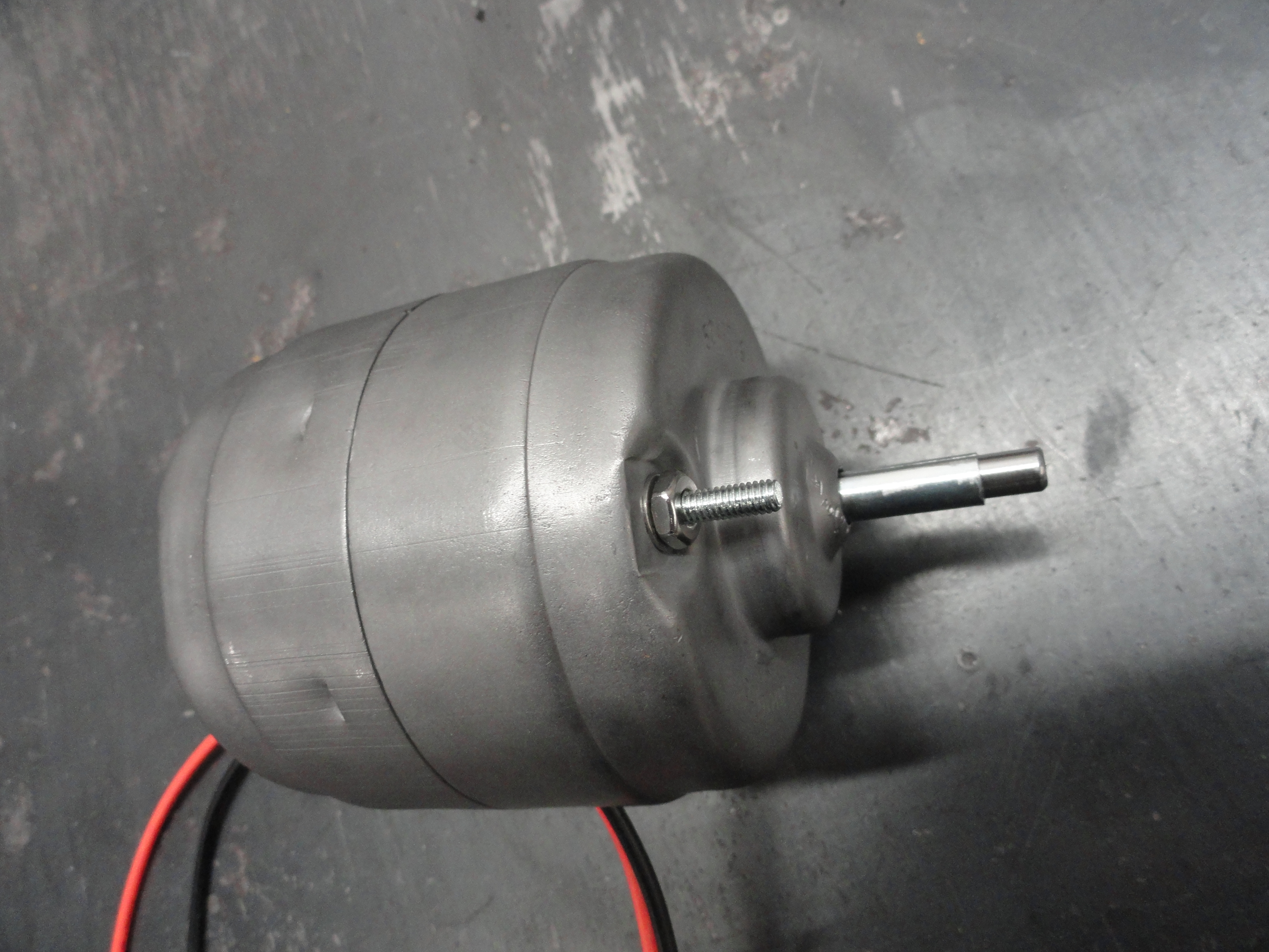
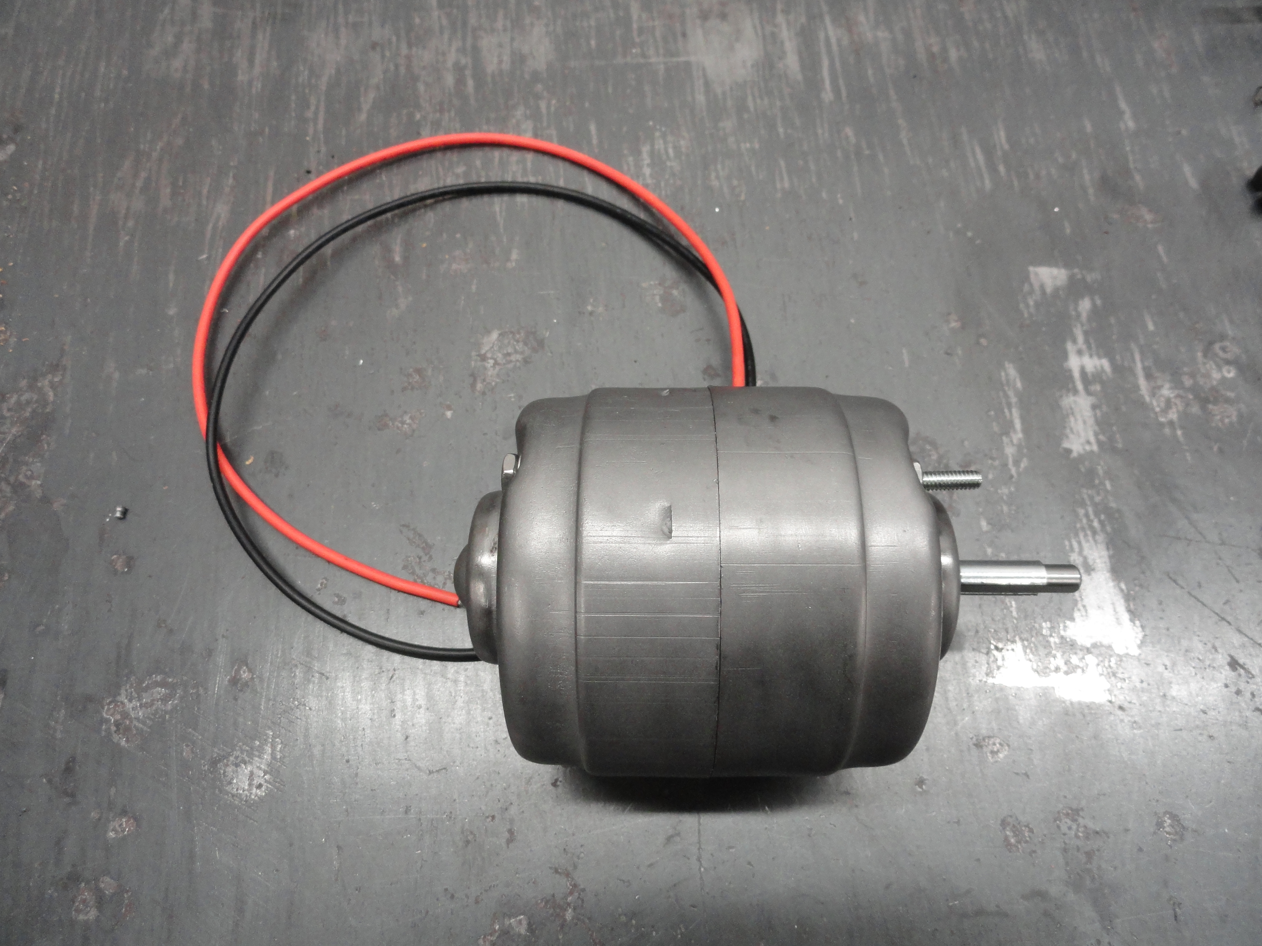
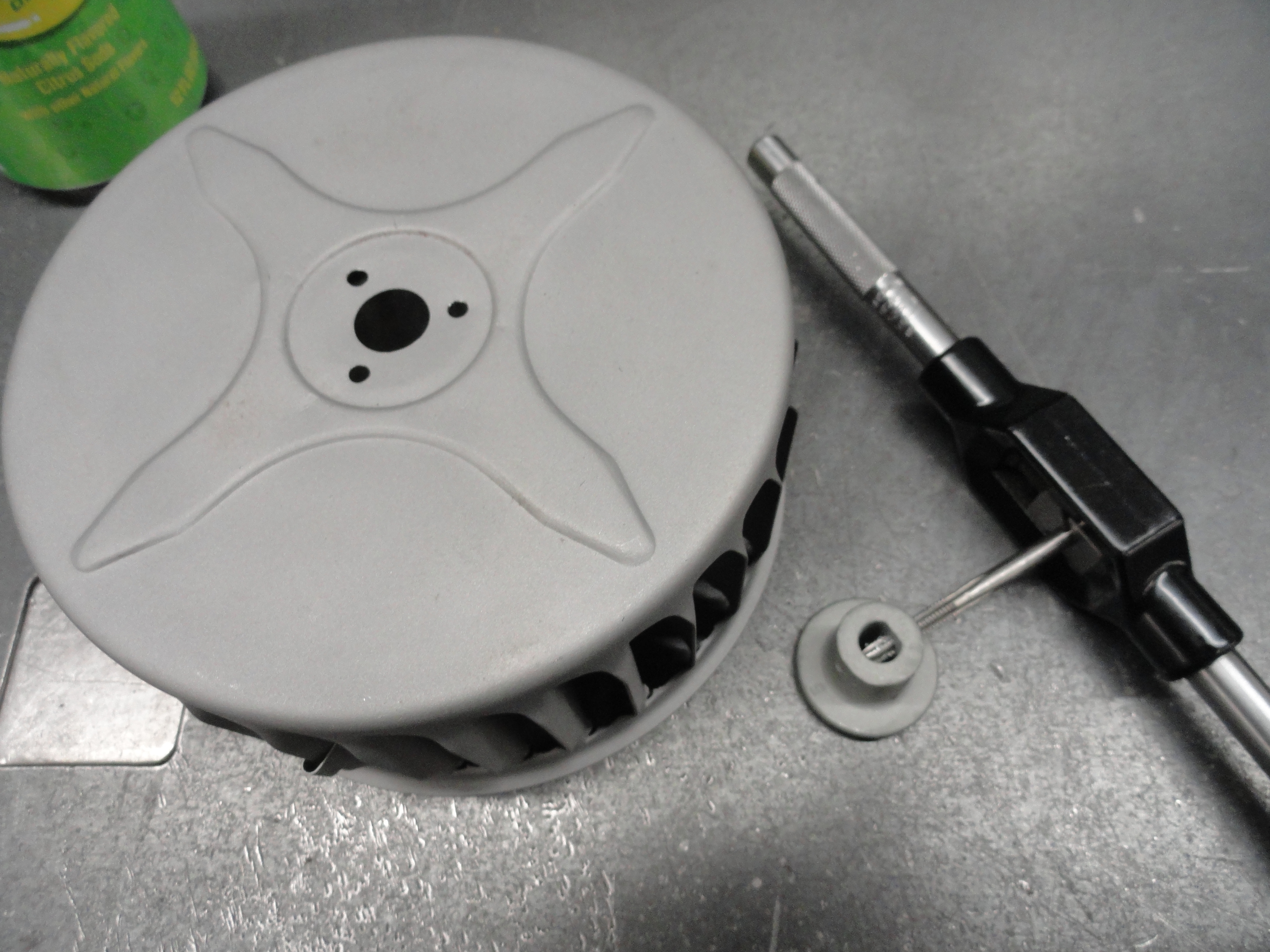
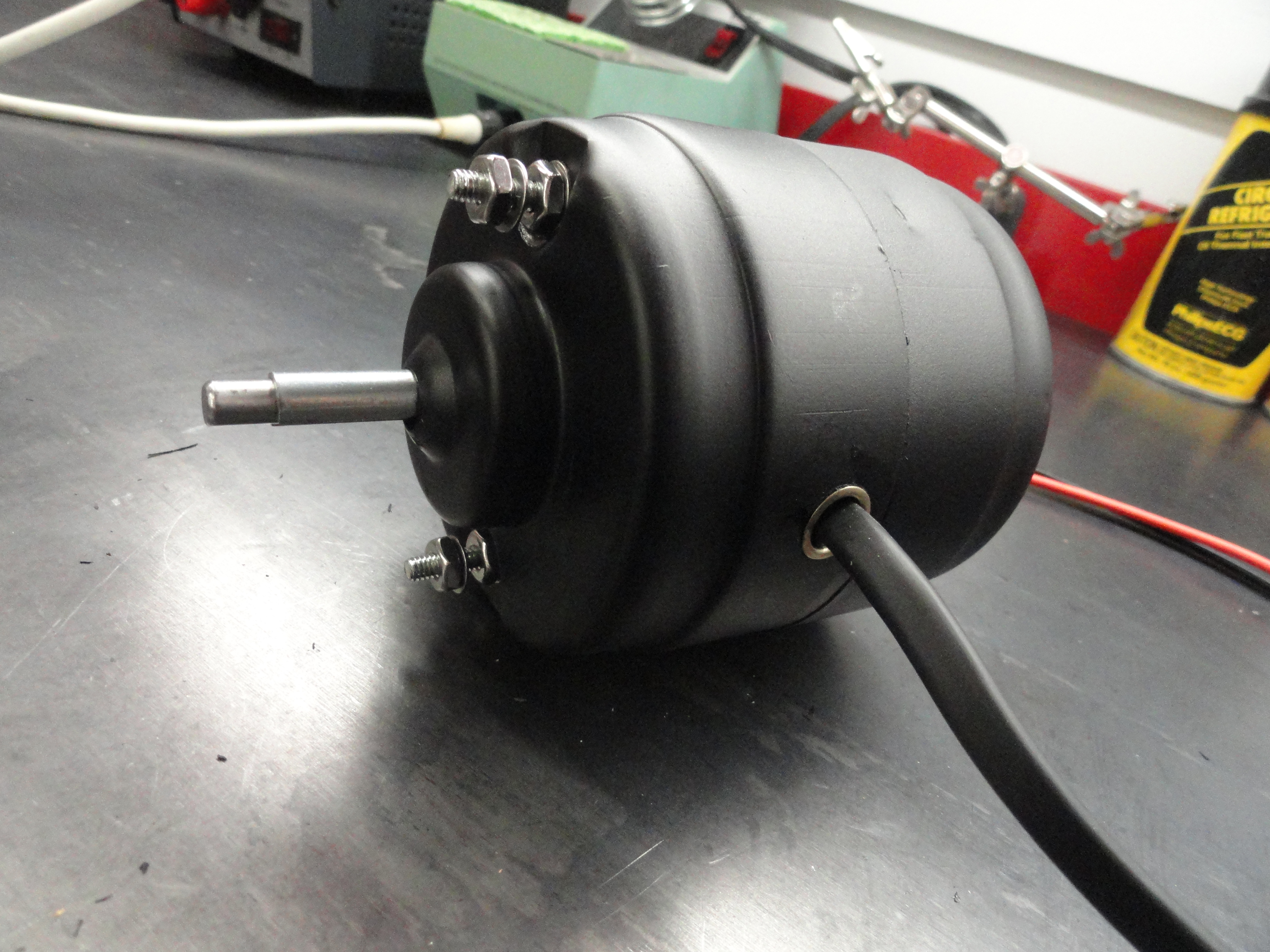
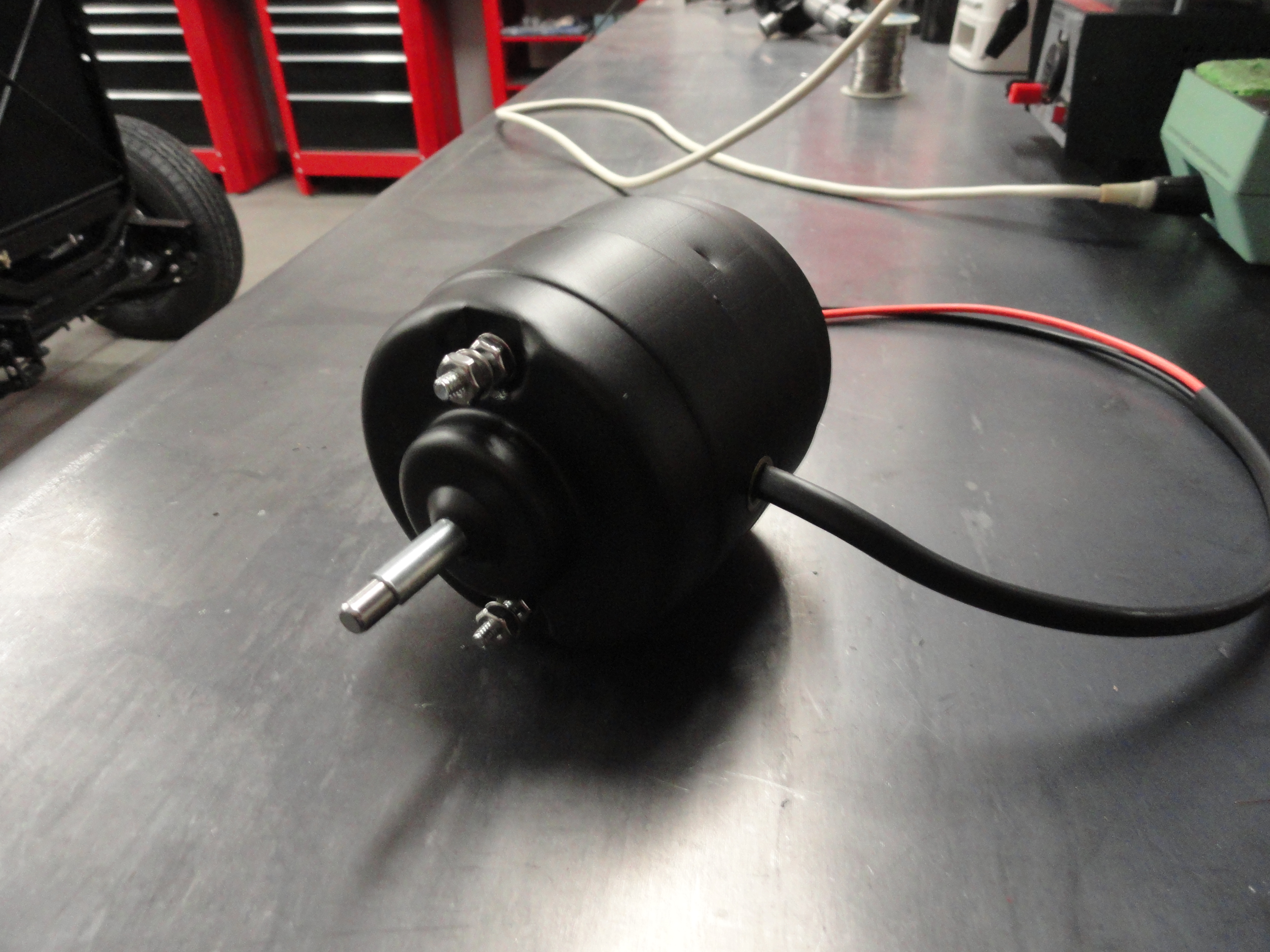
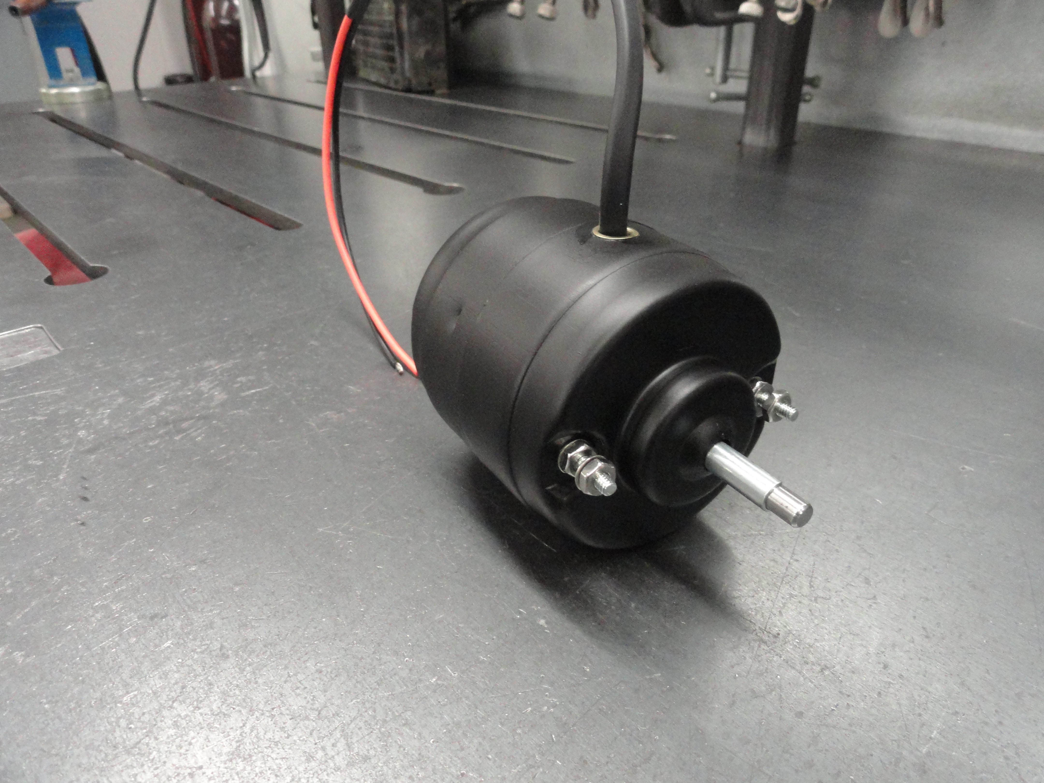
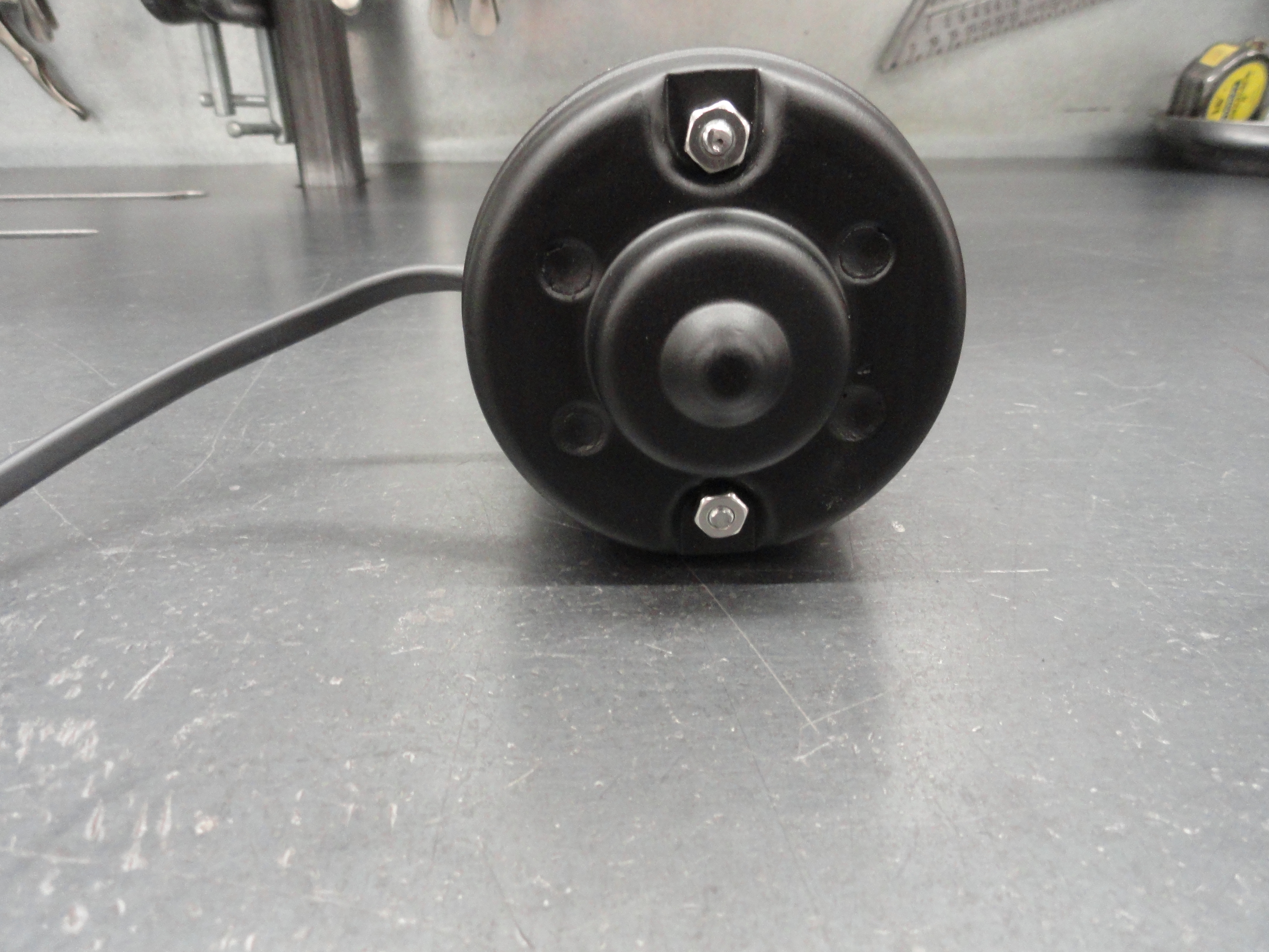
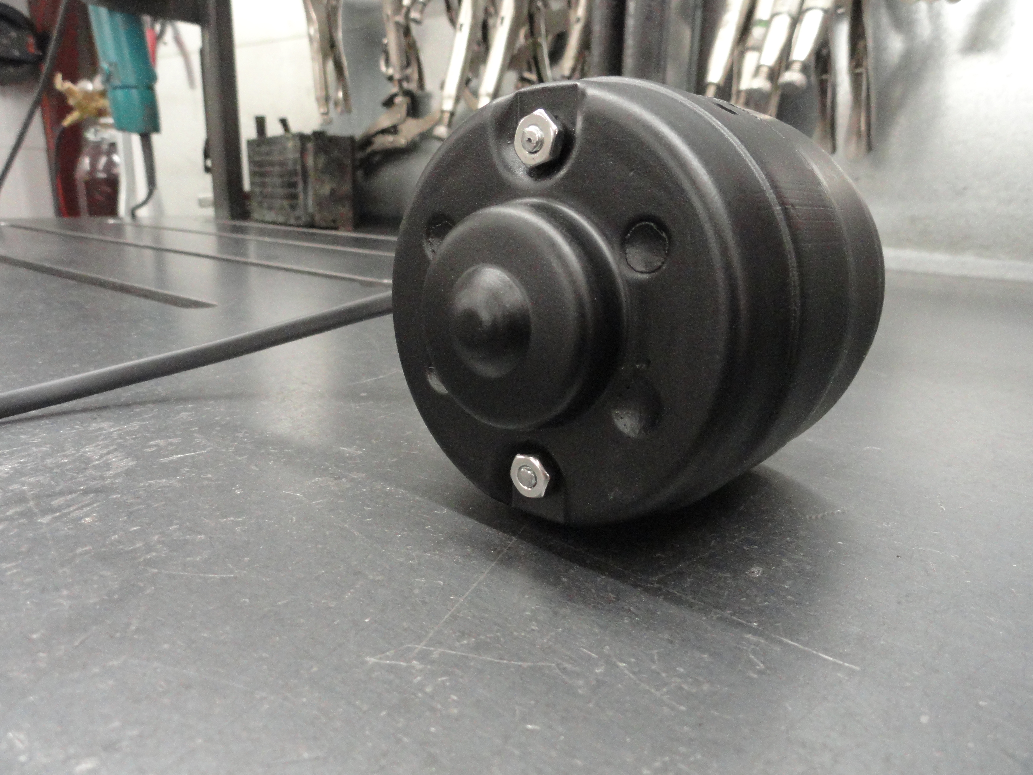
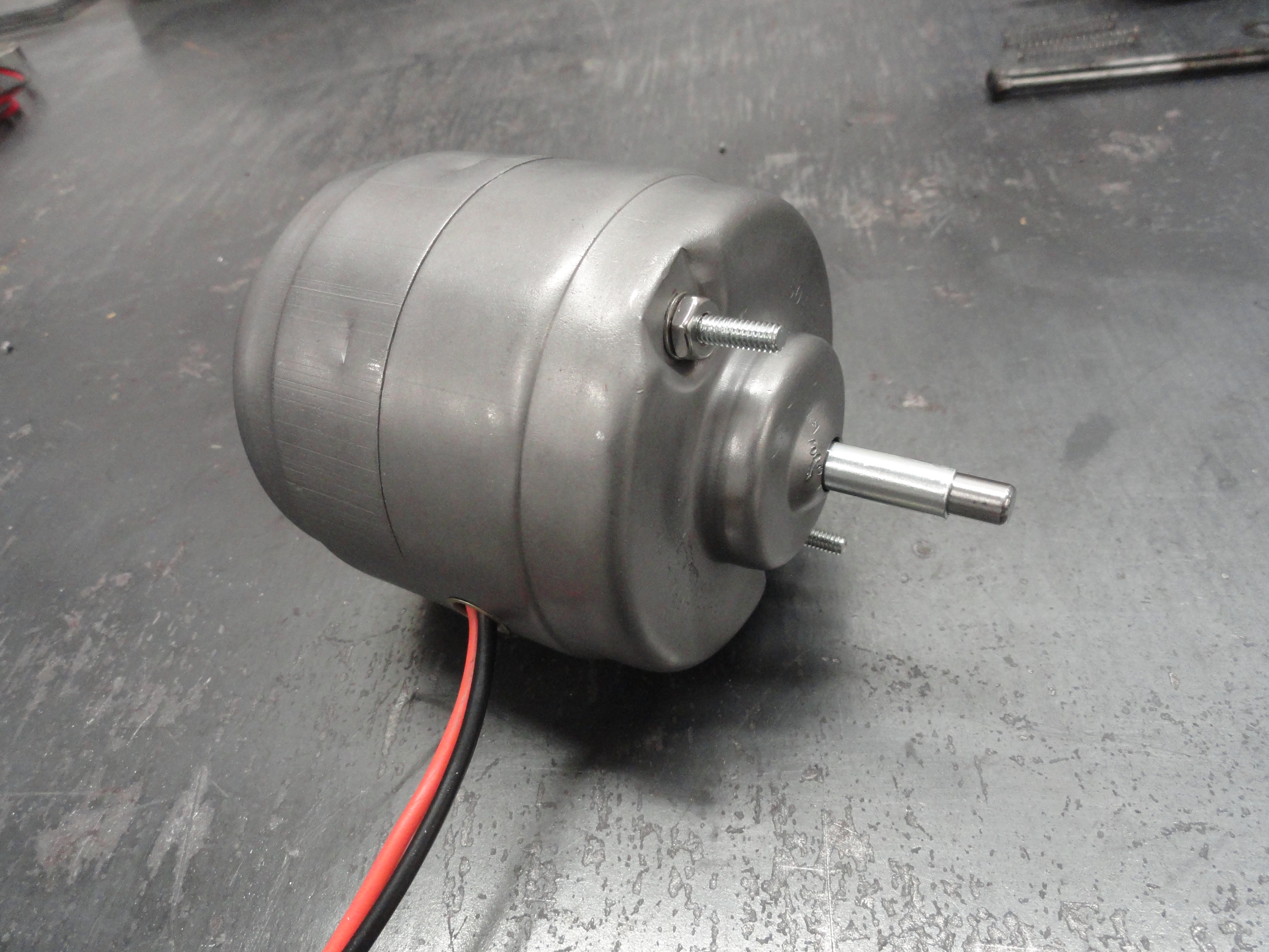
These are shots of the completed motor. I opted to close the 4 rivet holes on the bottom of the motor that were there to hold the brush block in with Permatex Black Gasket Sealer. By using masking tape to form a mold around the holes I was able to make it look like the contour belongs that way. Other than the stainless nuts and washers, this motor looks like it's factory new.
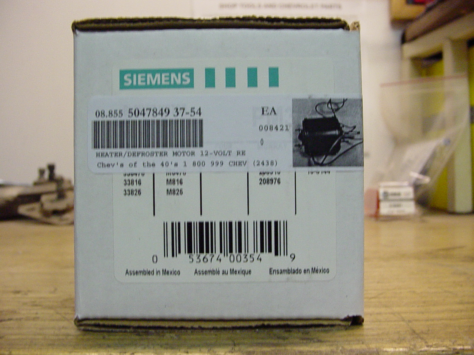
This picture is offered so that you can get the correct replacement motor when you call the Vendors. Also available from the usual vendors is the complete gasket set for these heaters and the decal for the defroster mechanism. Even the nice emblem is available.
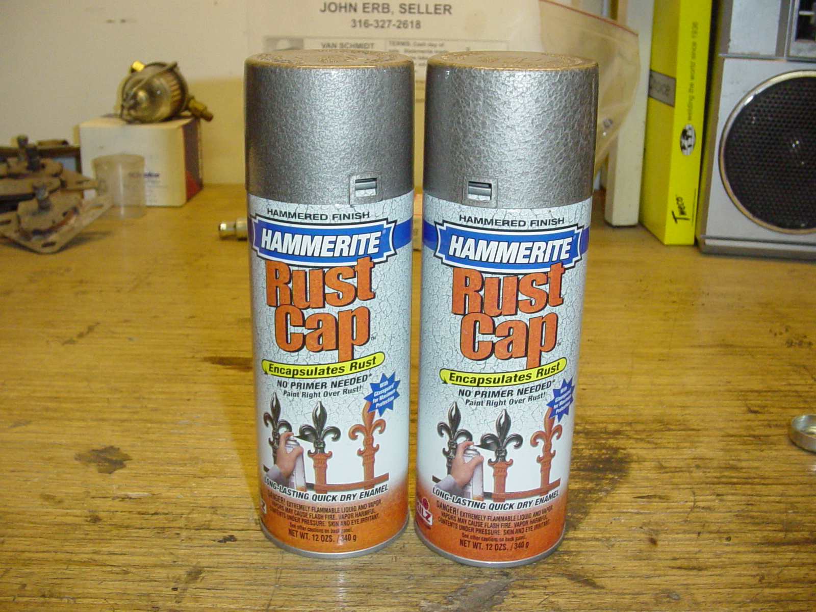
This is the paint I finally decided on. You can get heater paint from any of the vendors, but this product is a name brand and is a perfect factory fresh match. The best part is that it is in aerosol cans so its very easy to use. Use a swirling motion and be sure to shake the can extra well. Two cans is more than enough to do an entire heater. The paint is made by the Kilz corporation and its called Hammerite Rust Cap Bronze. Eastwood sells it.

Here are the parts all laid out and painted. They came out absolutely perfect. The color and the finish is amazing. I painted the inside of each piece first so that I could test my technique on an area that wouldn't be seen. I let the first side dry overnight and then came in the next day and painted the outside. I then let the job set for 3 days before re-assembly.
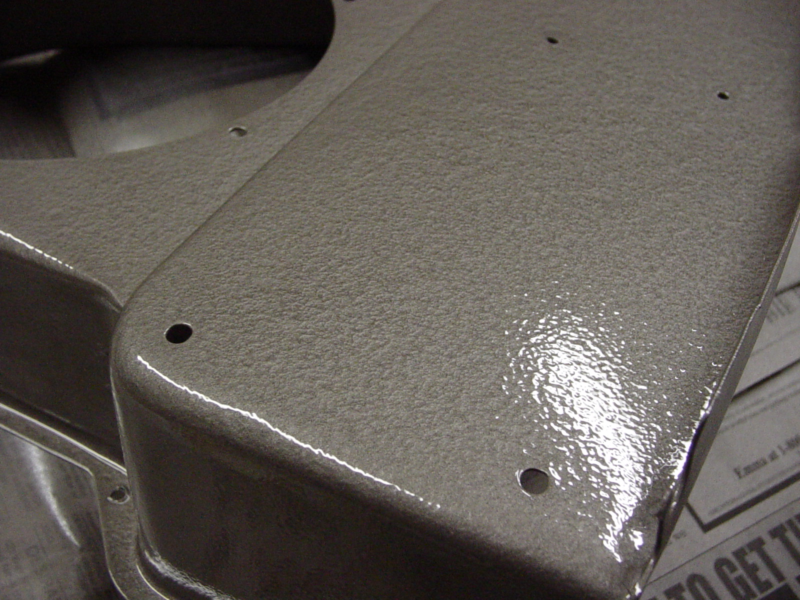
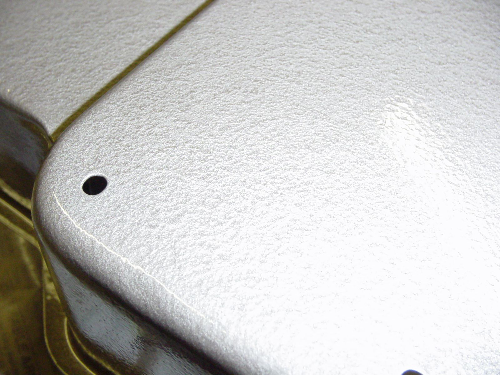
This is just a close-up of the work so you can see the hammered finish. It looks so original. The colors in these pictures don't do the work justice. My digital camera and the color of the fluorescent lights in the shop change its appearance.
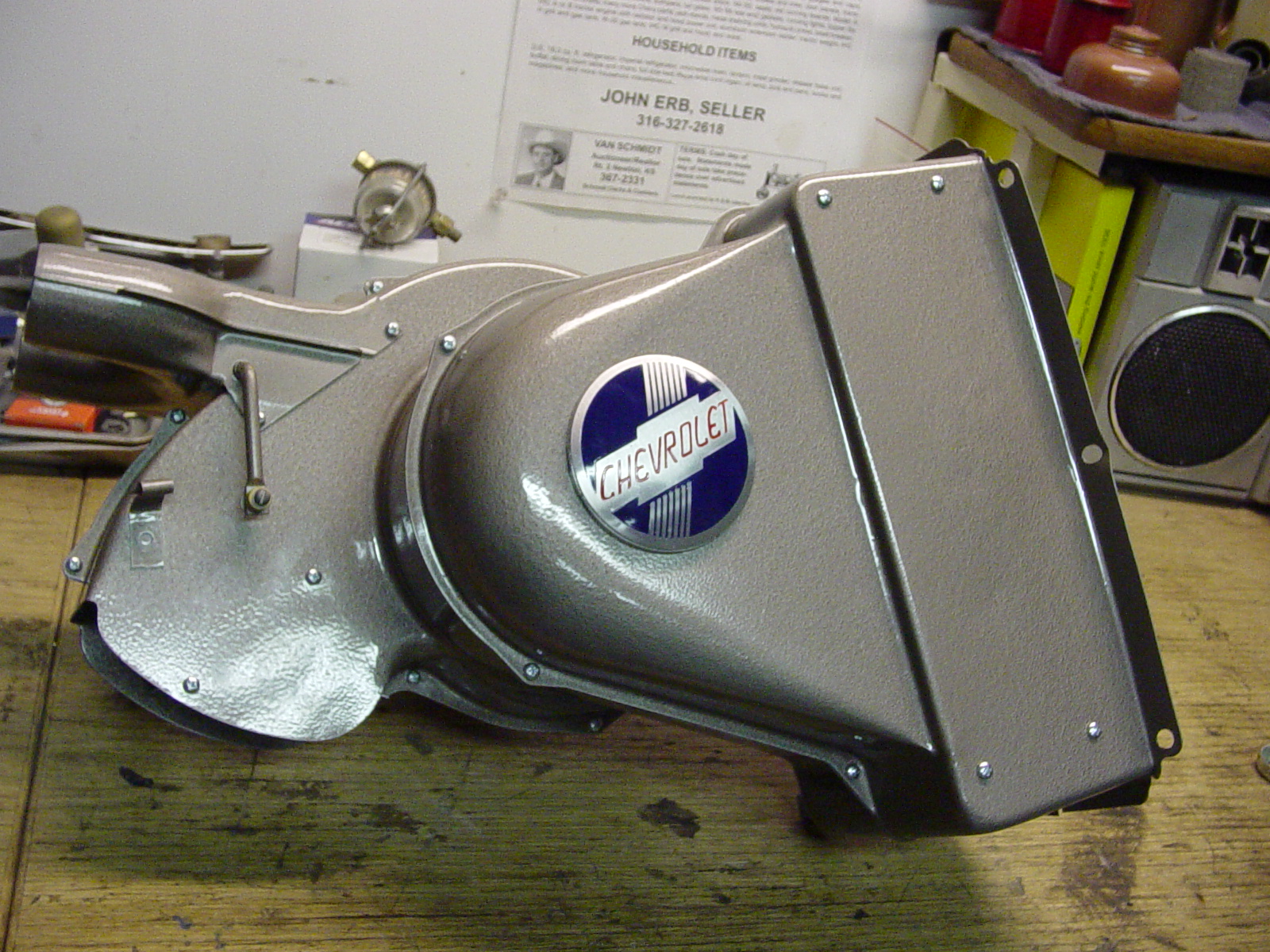
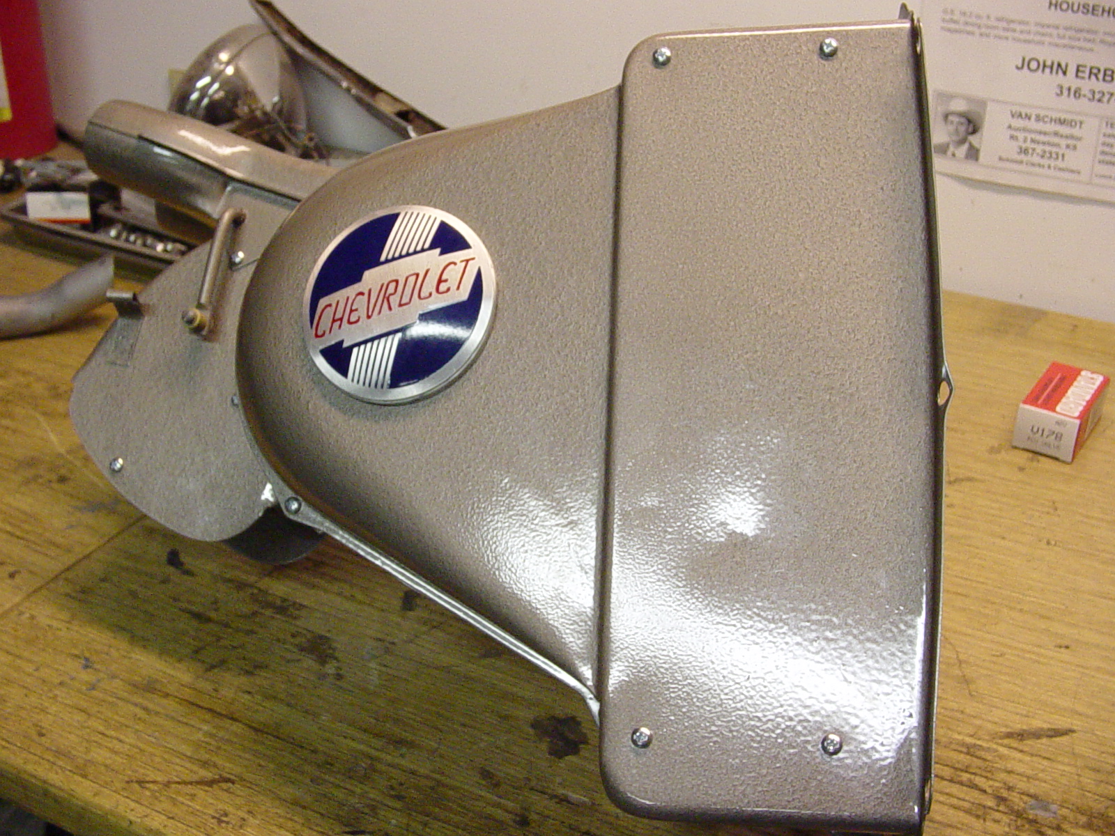
Thanks to the previous pictures, I figured out how to put it back together! I think this heater will look very nice in my '50 frame up restoration project.
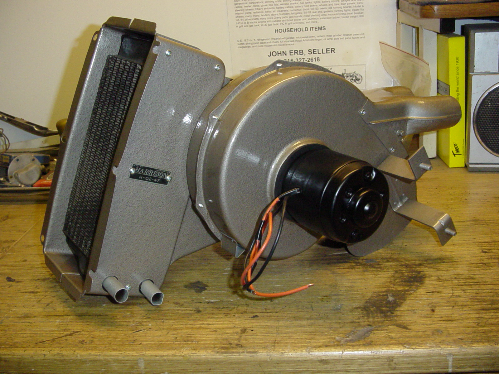
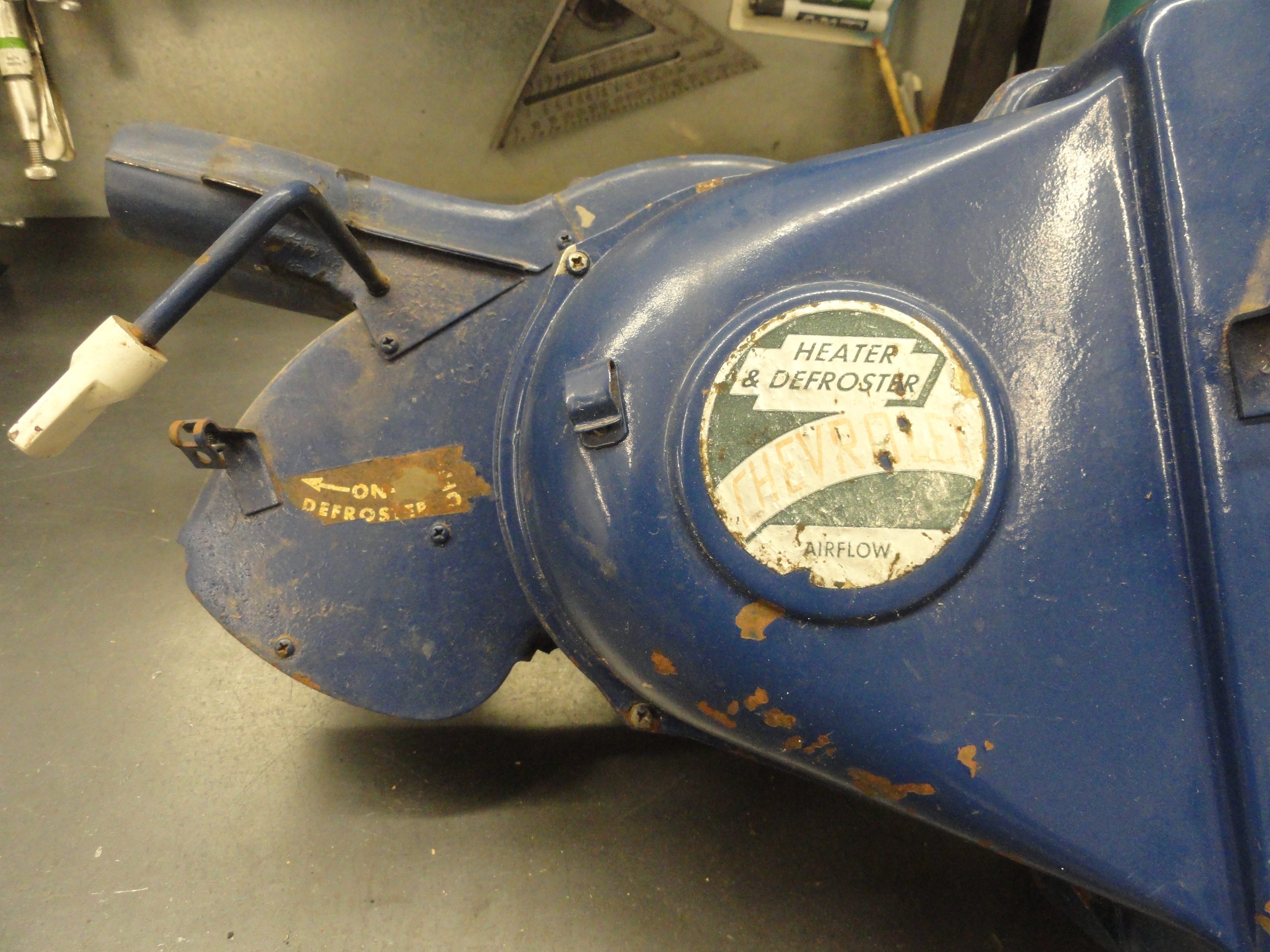
Notice the motor. It looks exactly like the 6 volt original. After I shot these pictures, I added the proper defroster decal. The 'Chevrolet' emblem is not a decal. It is a faceplate and you can get that from most of the vendors. I used JBWeld to attach it to the original plate once I polished the sides of it.
Here is the before and after. You have to really see it to believe it!
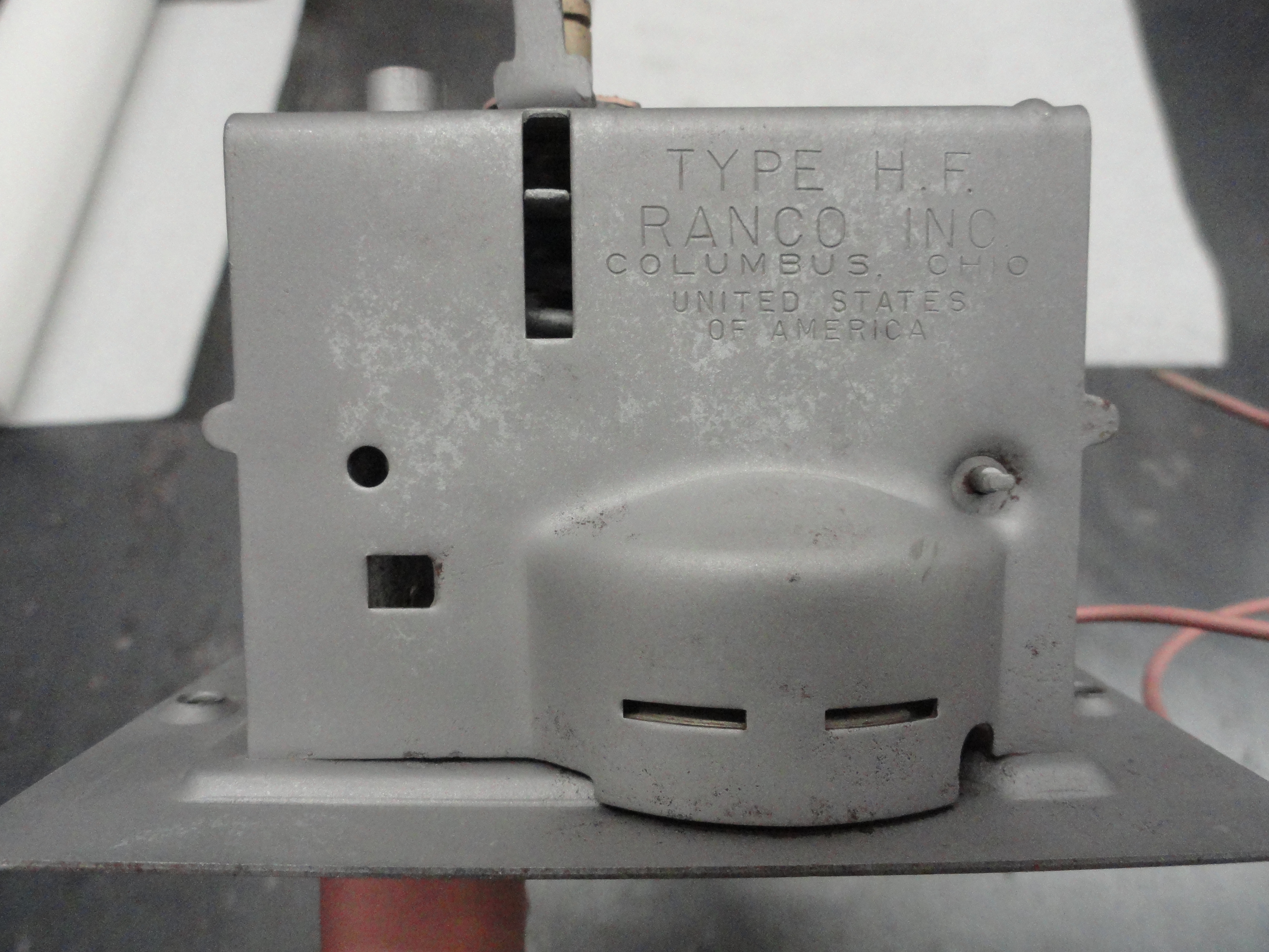
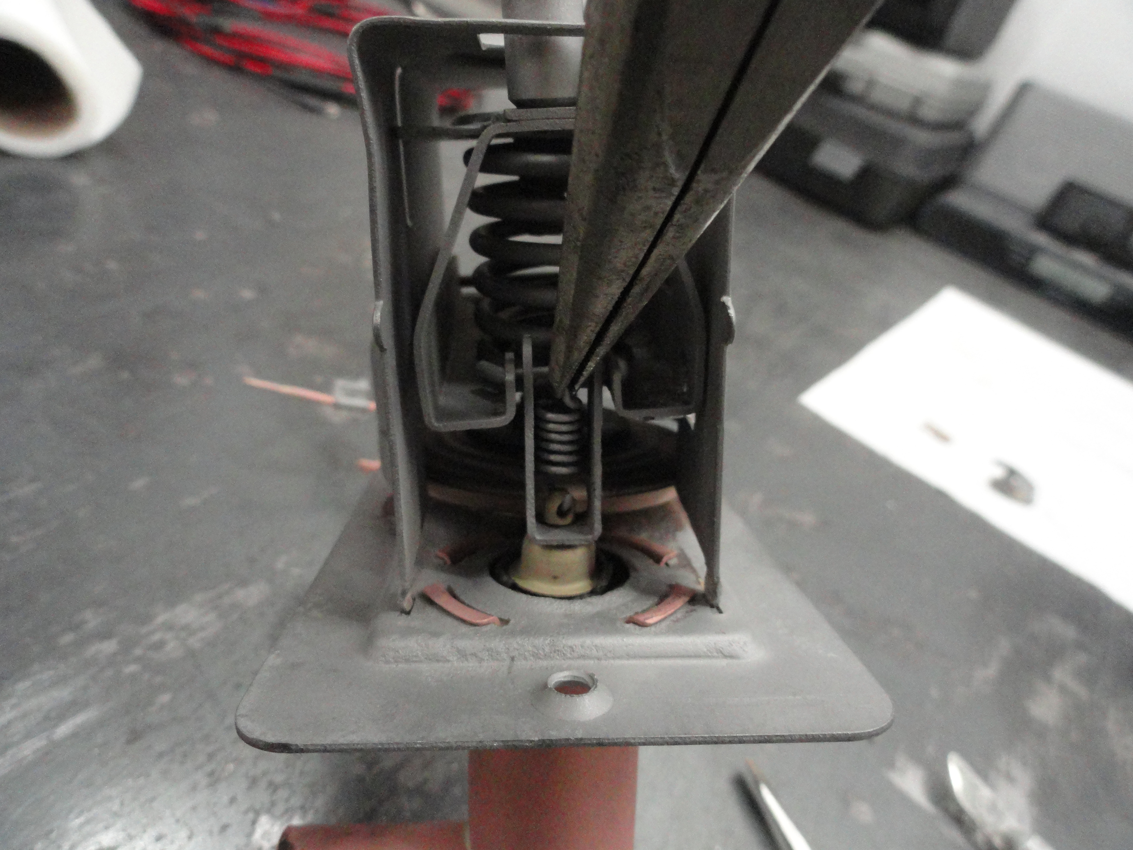
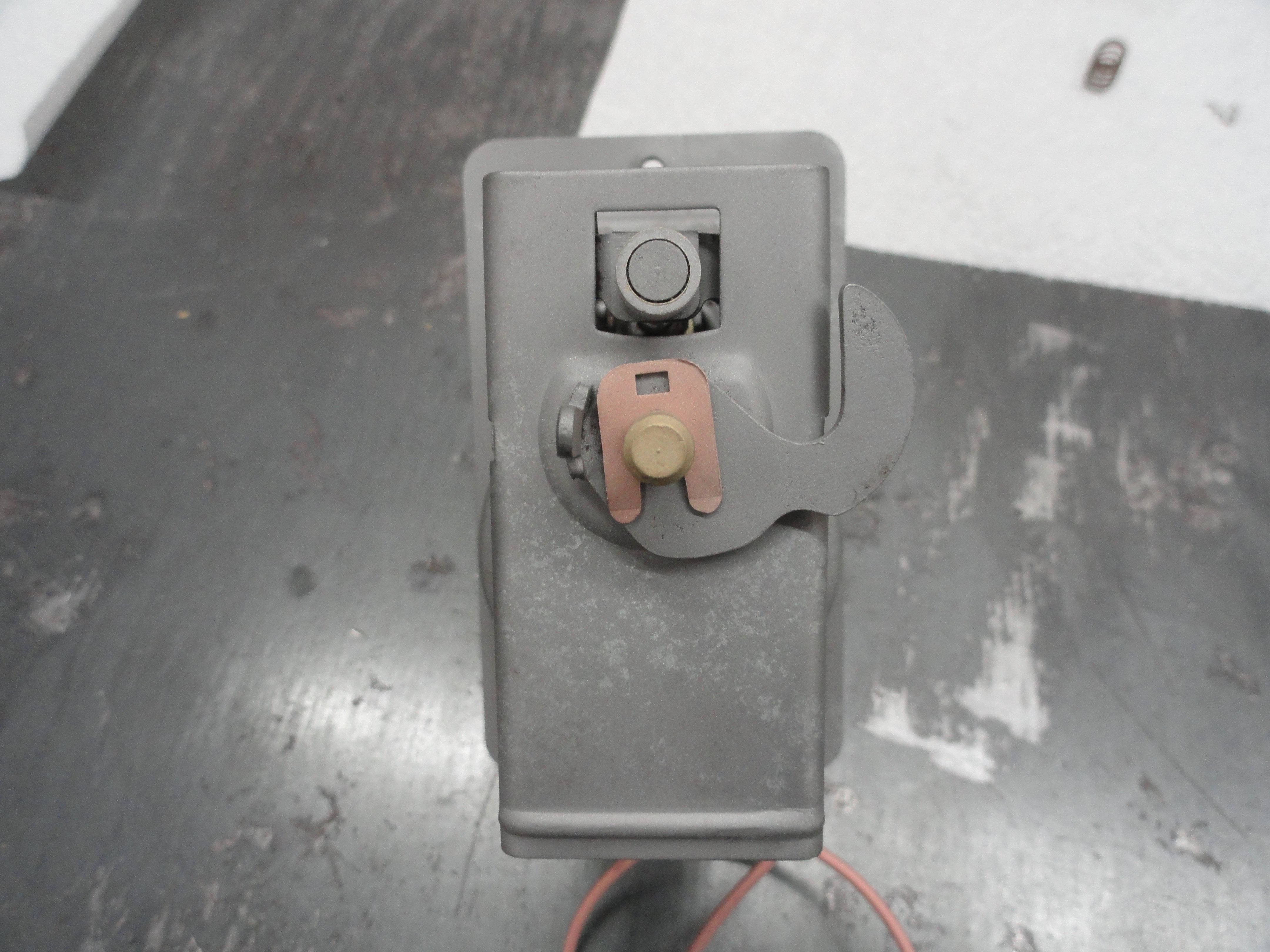
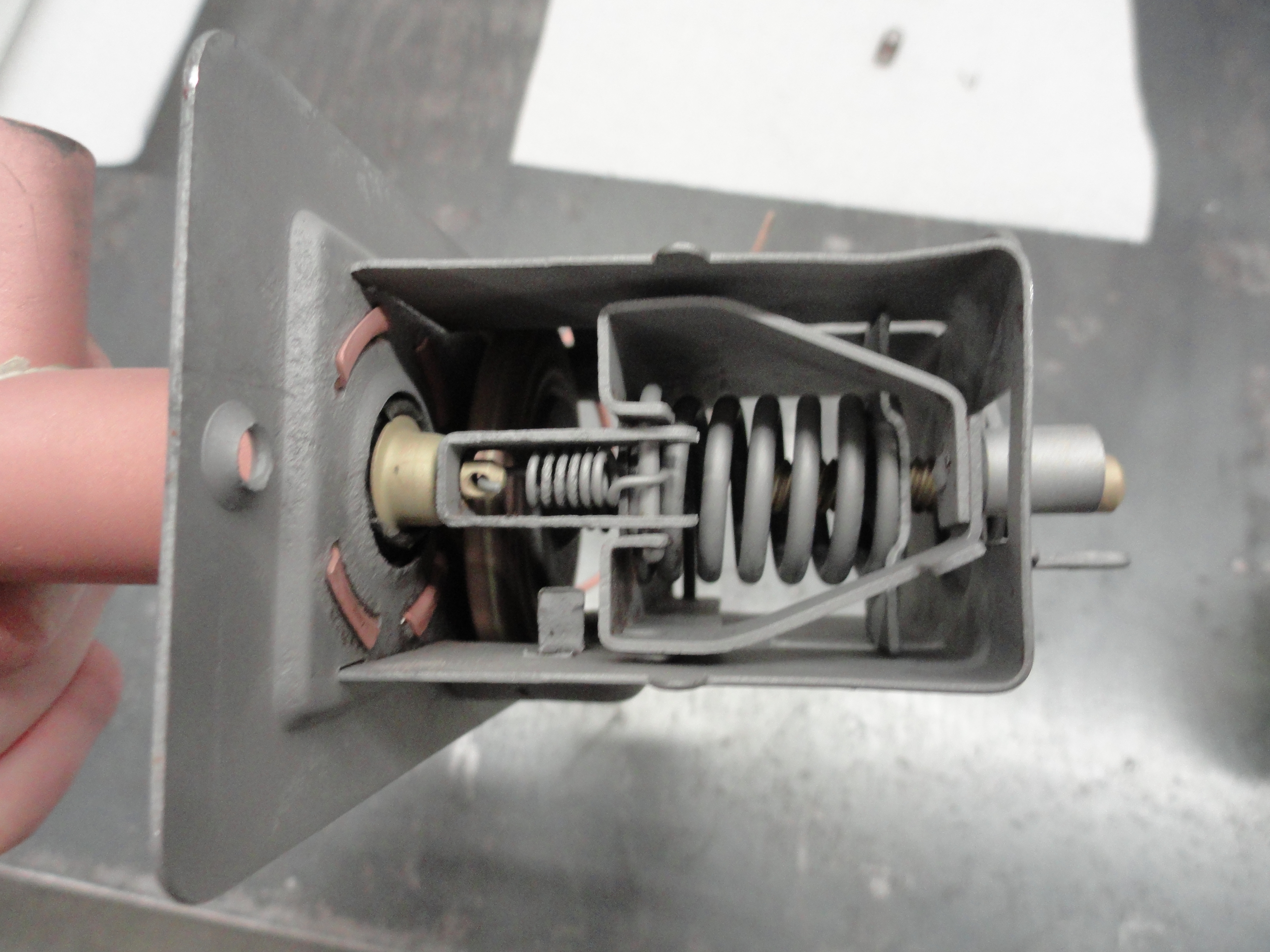
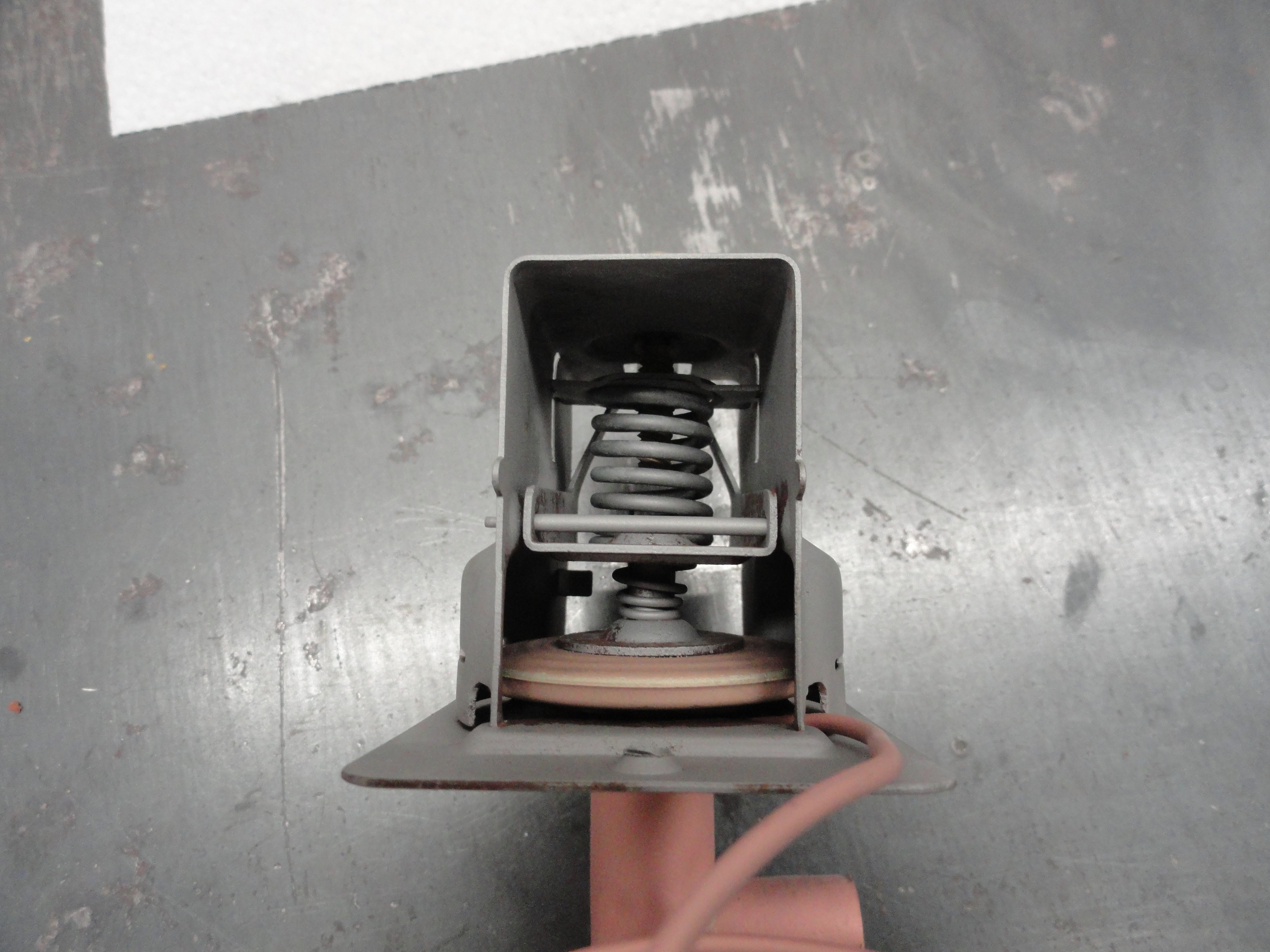
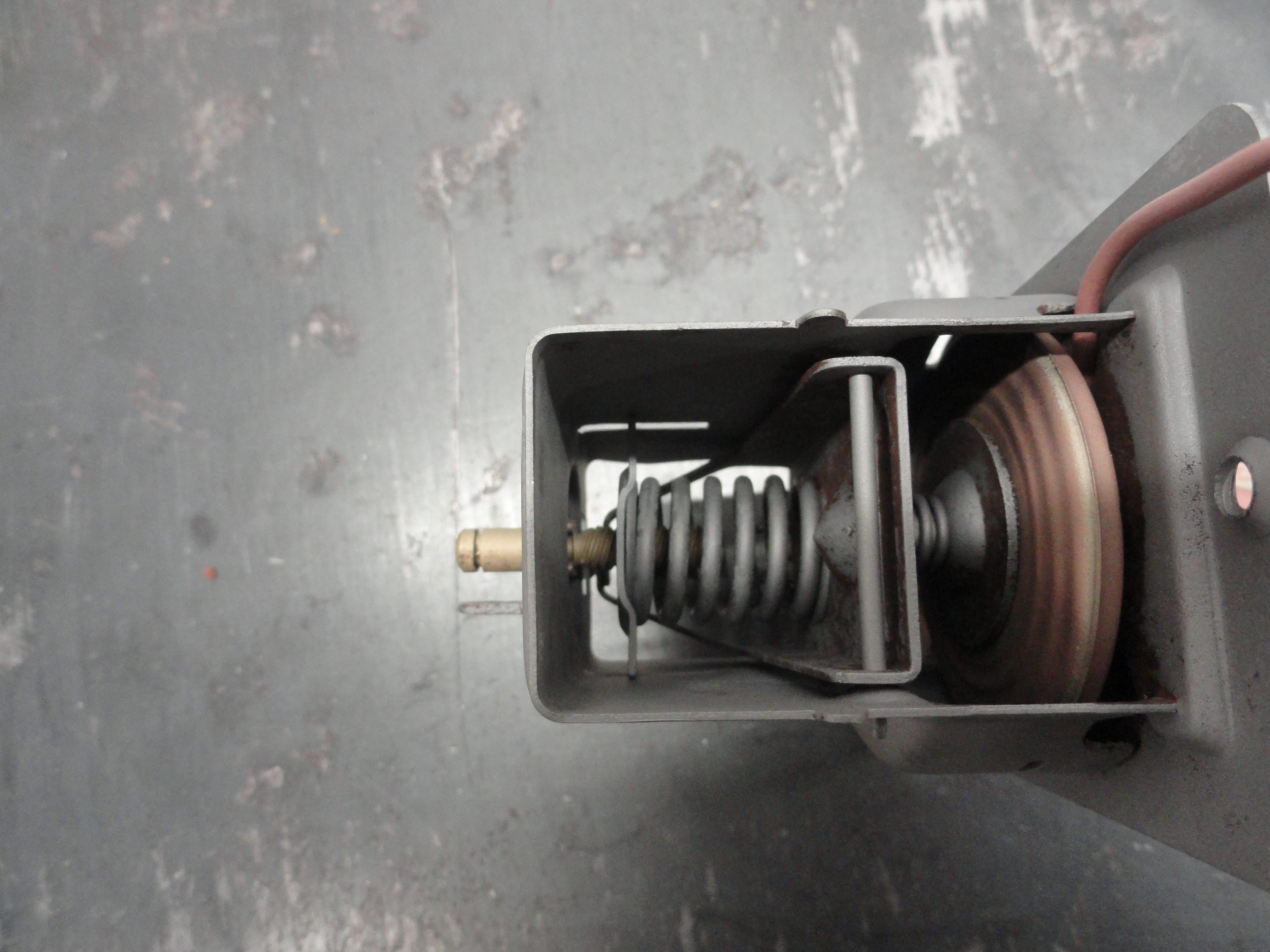
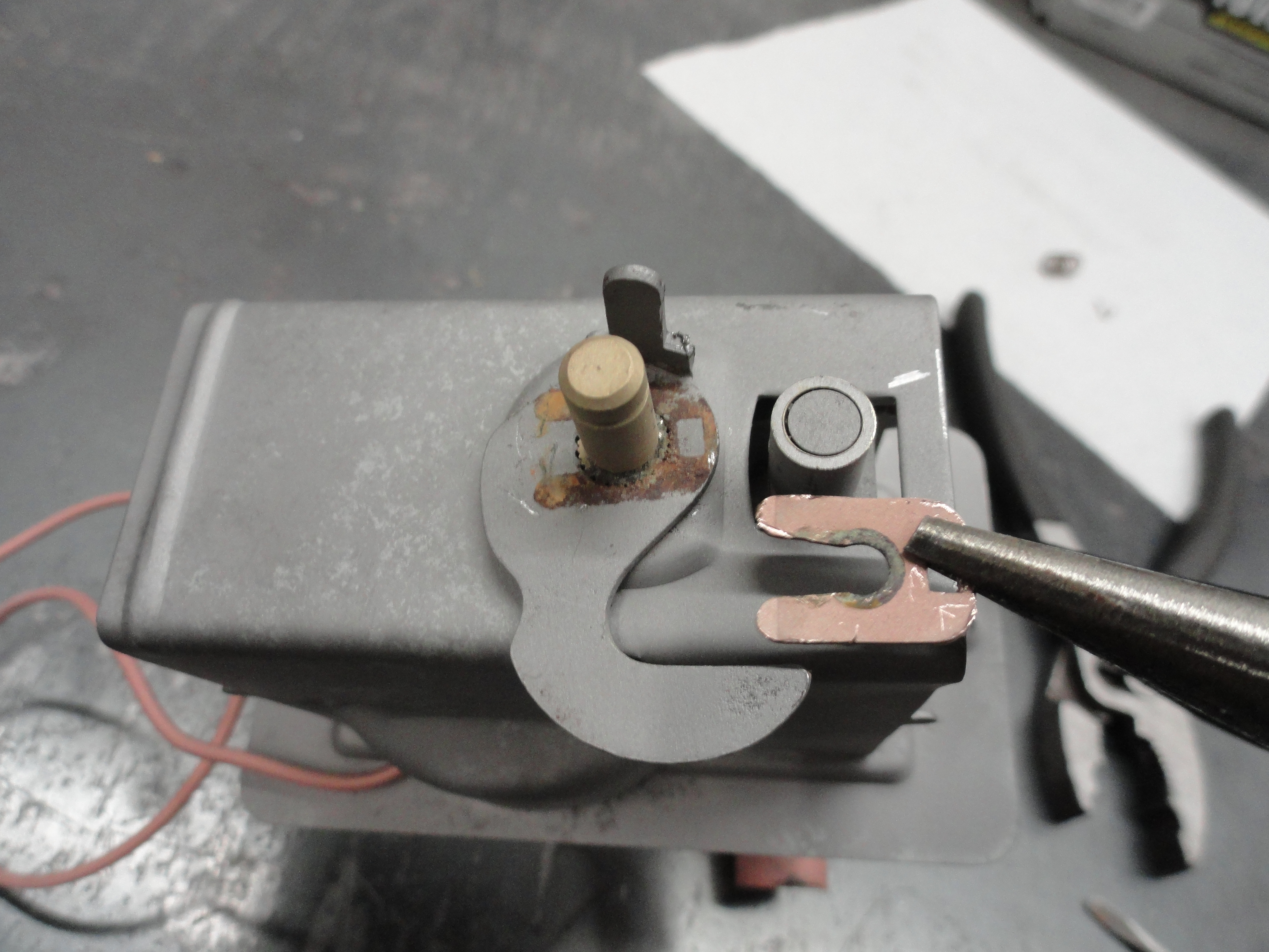
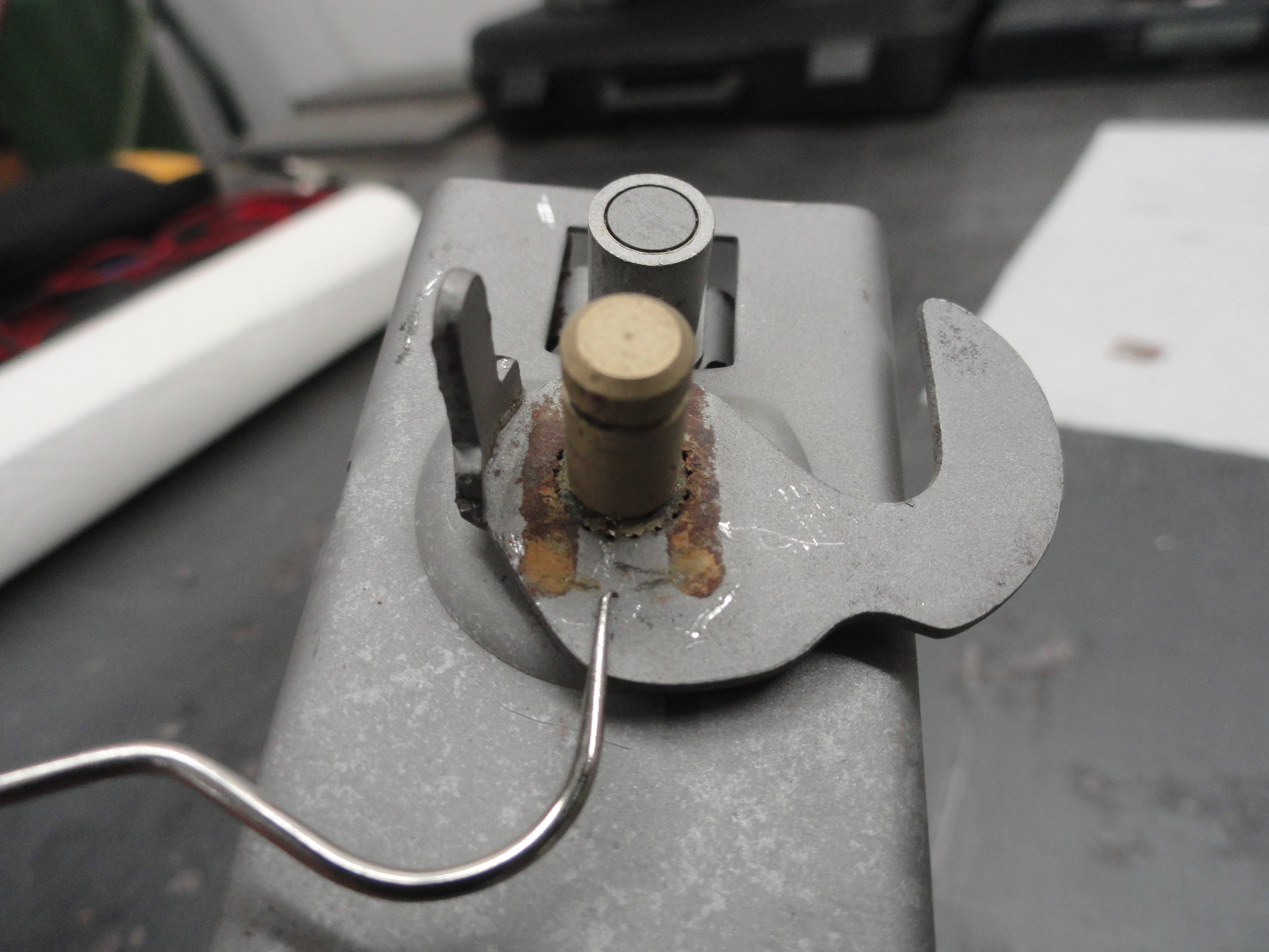
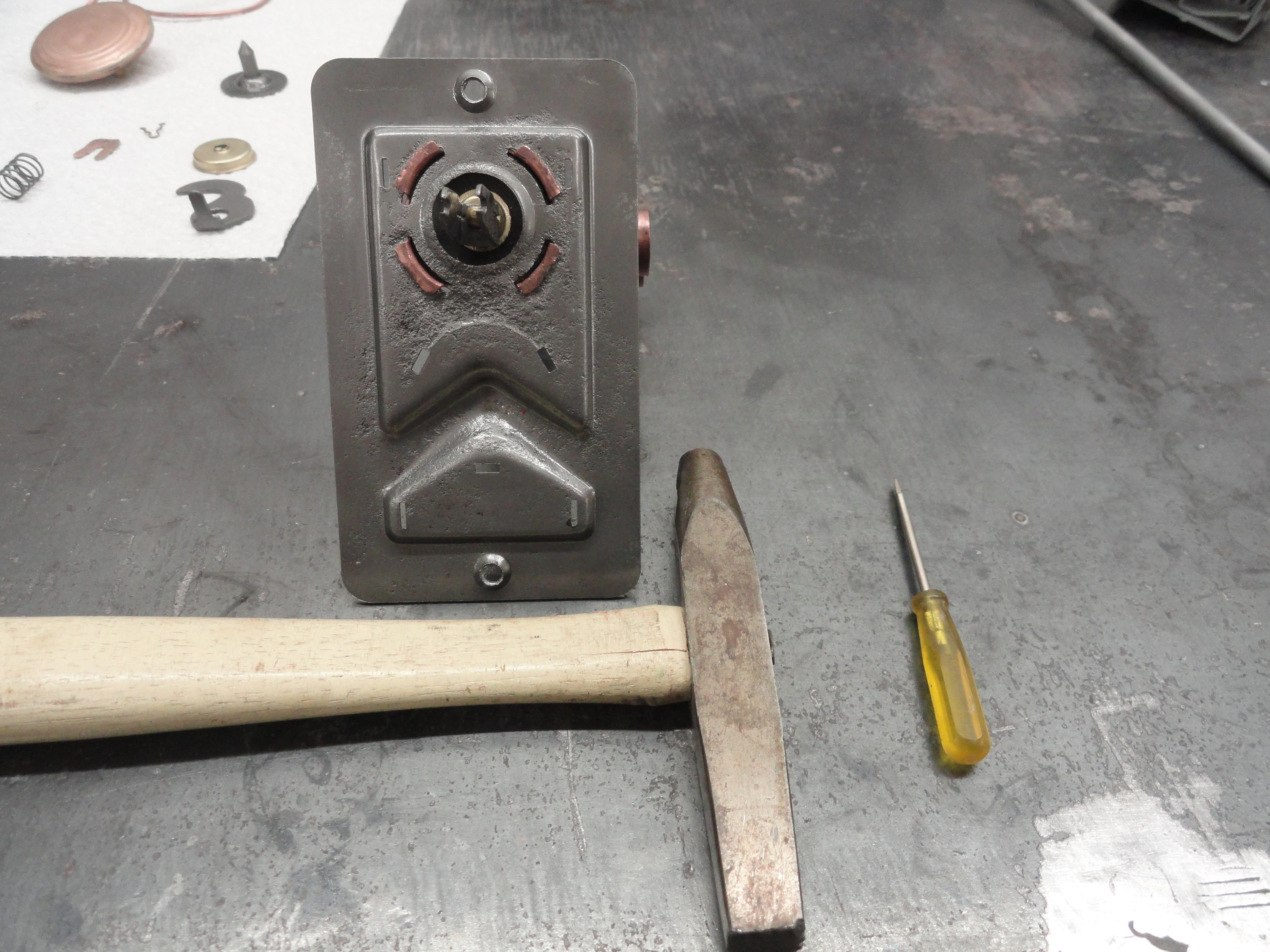
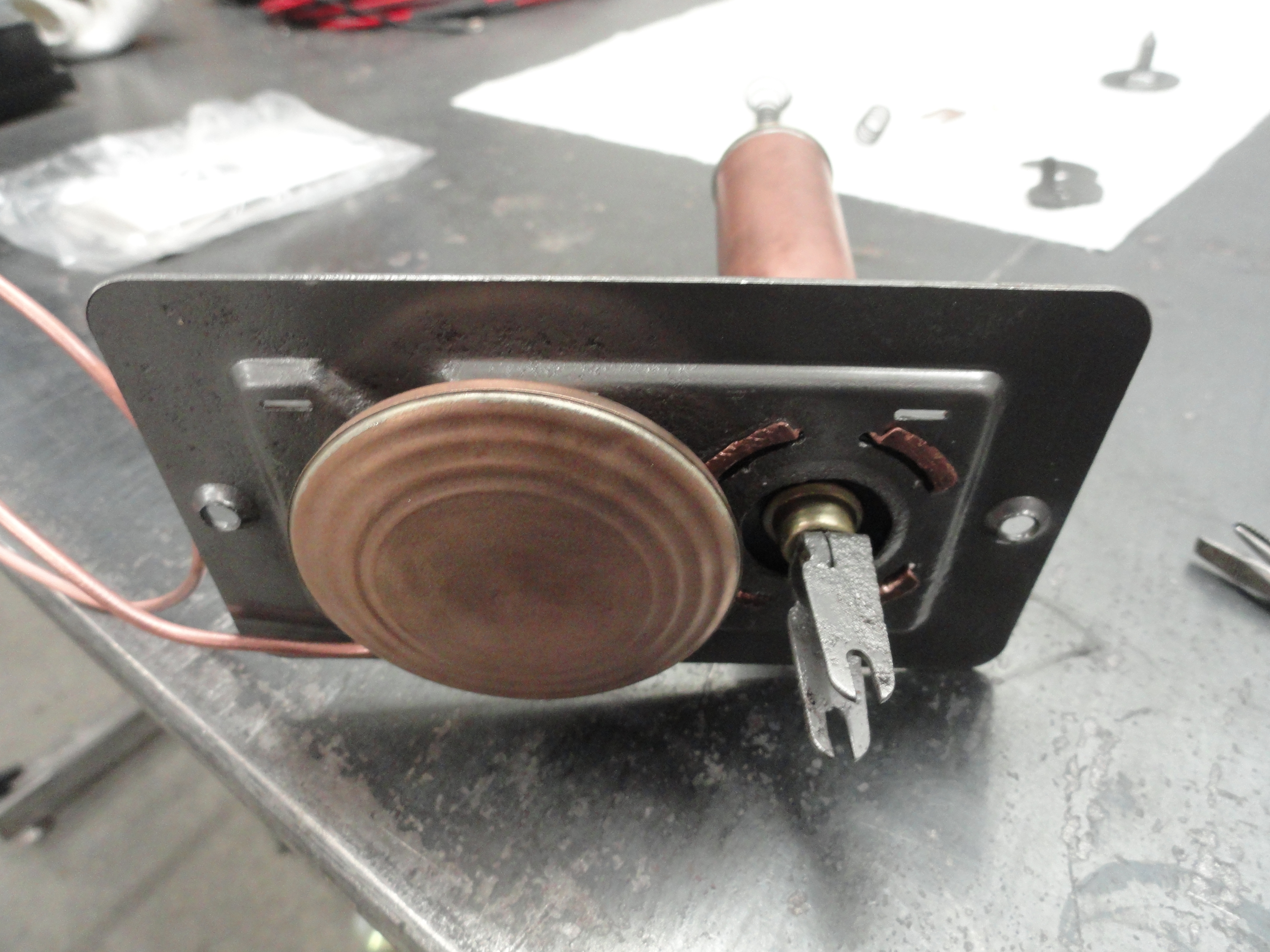
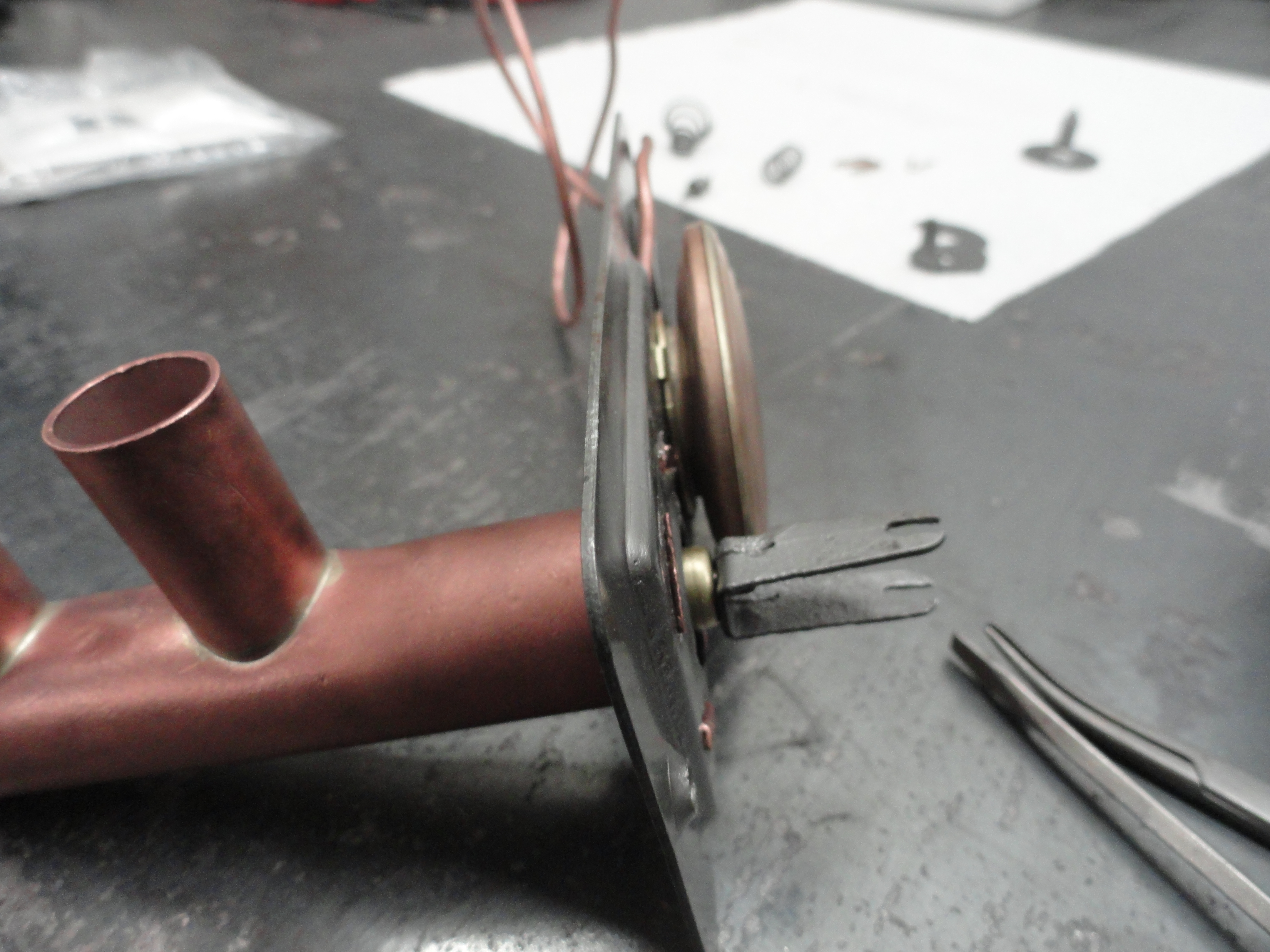
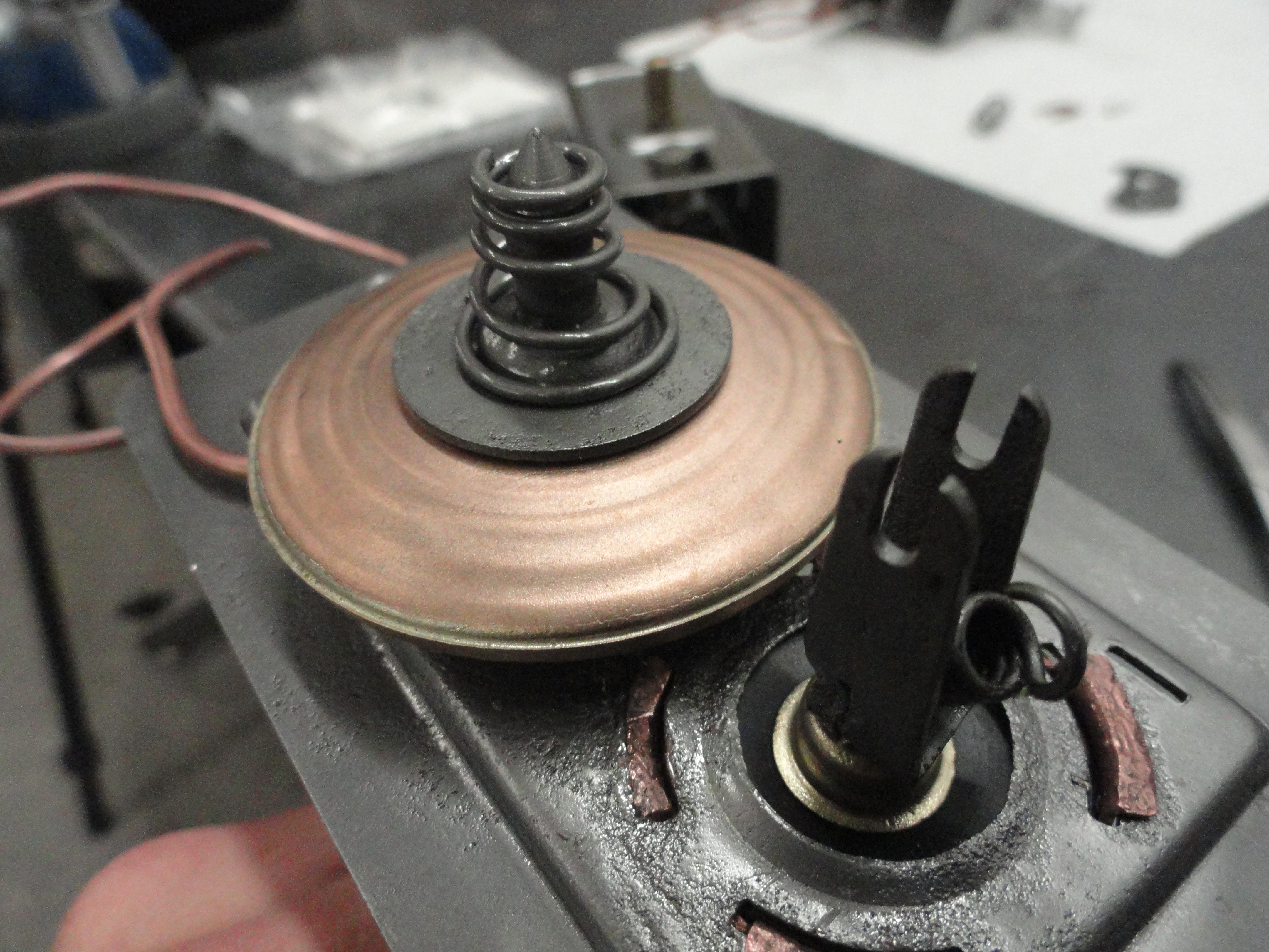
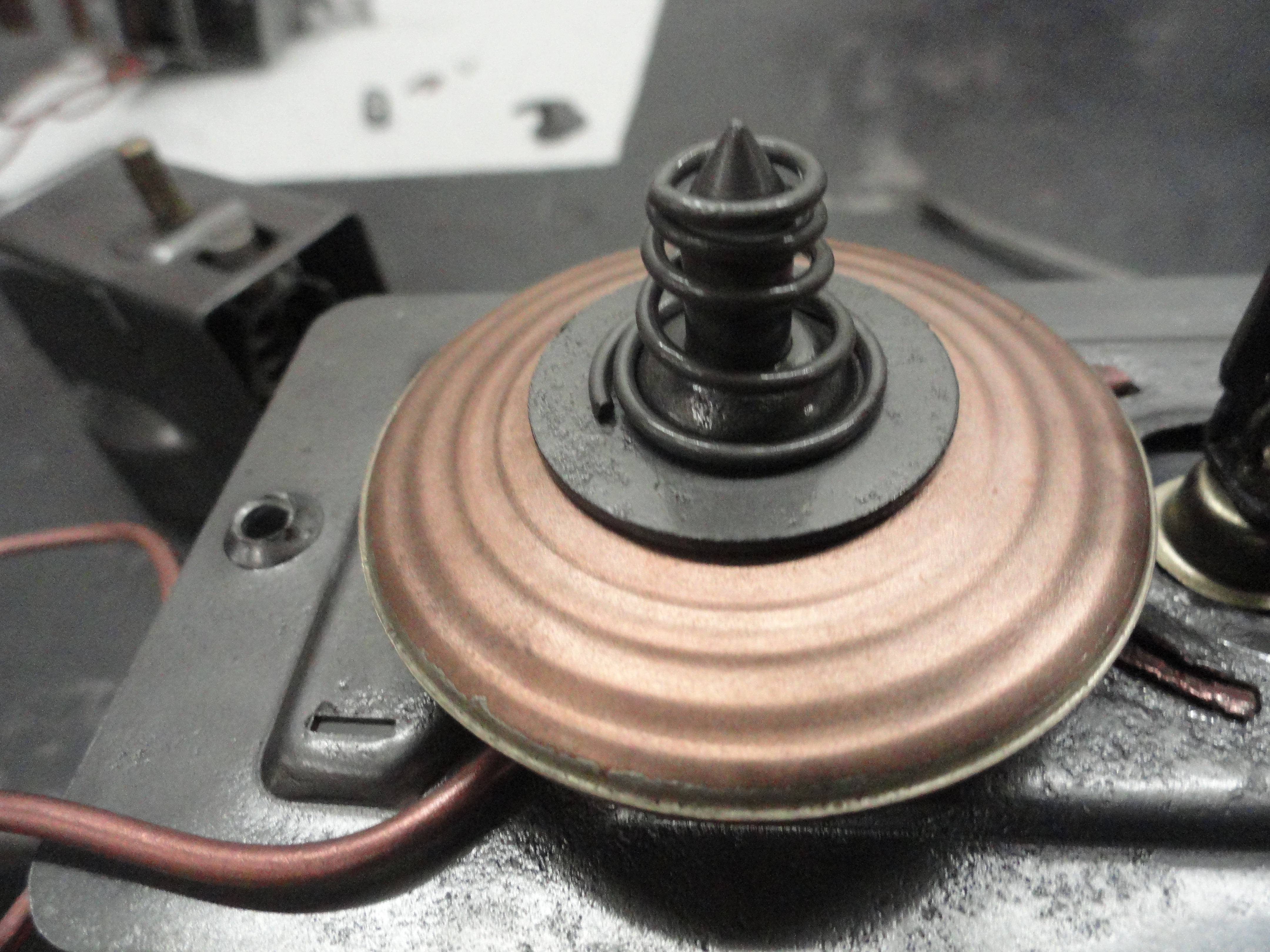
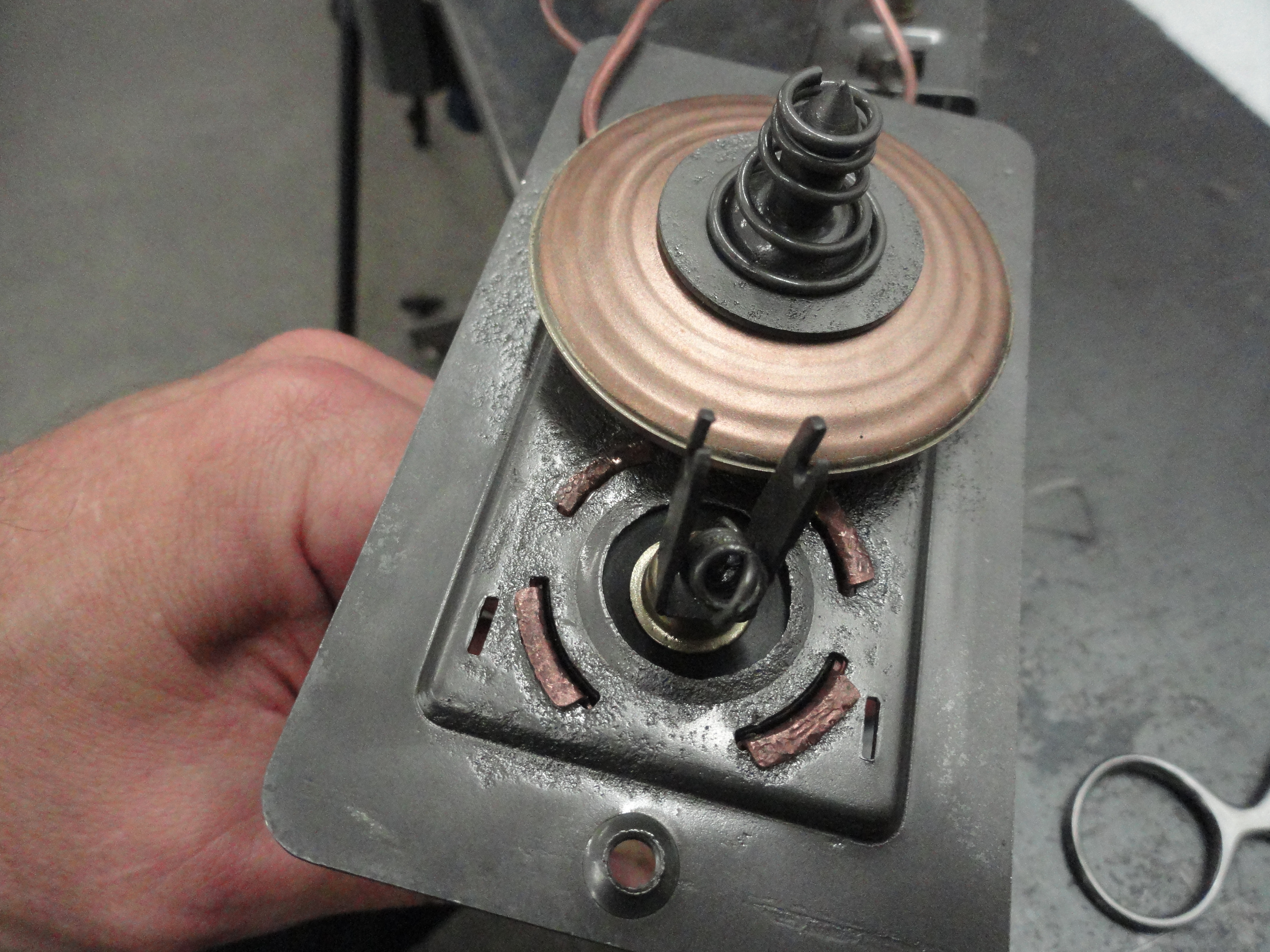
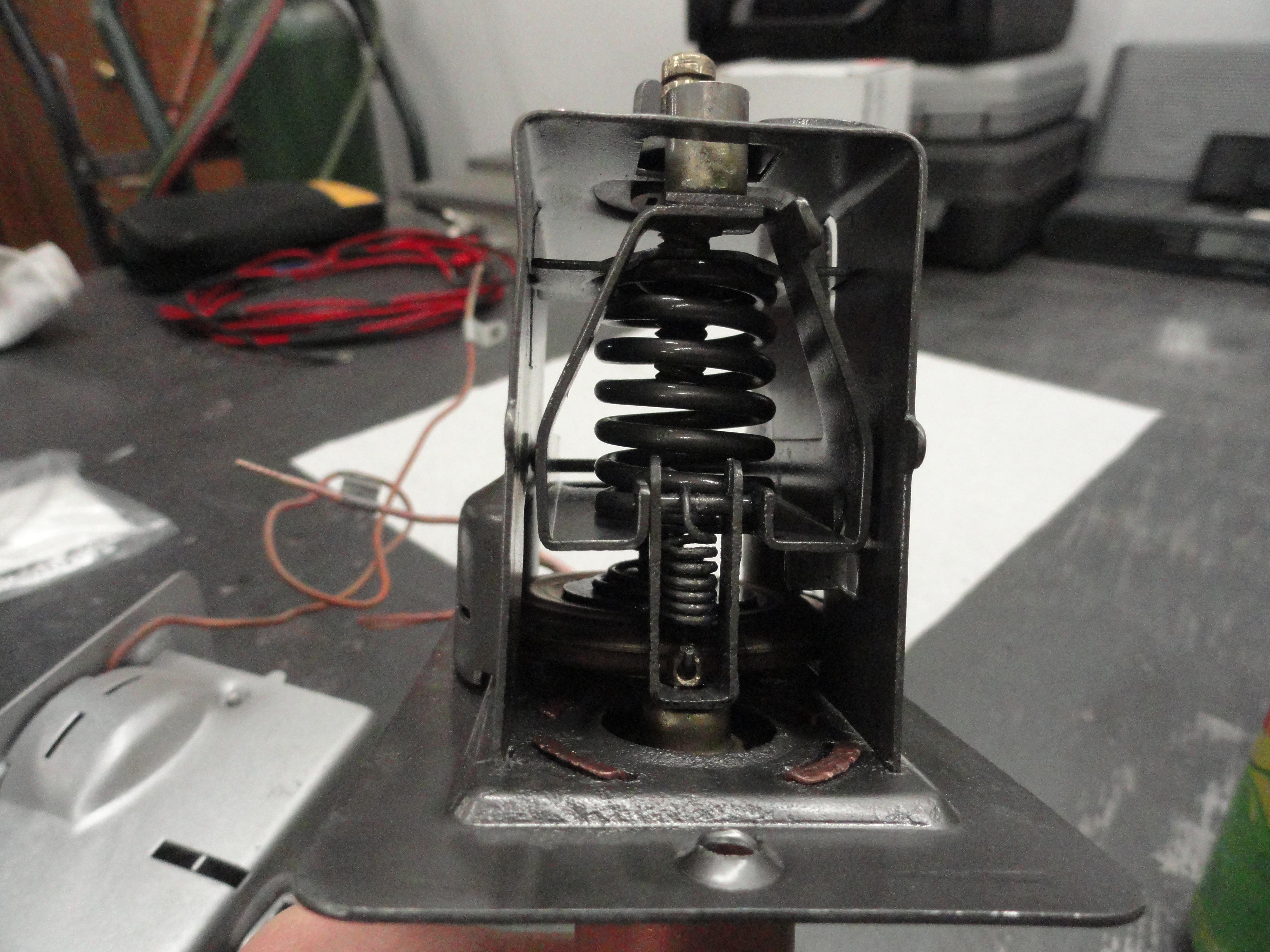
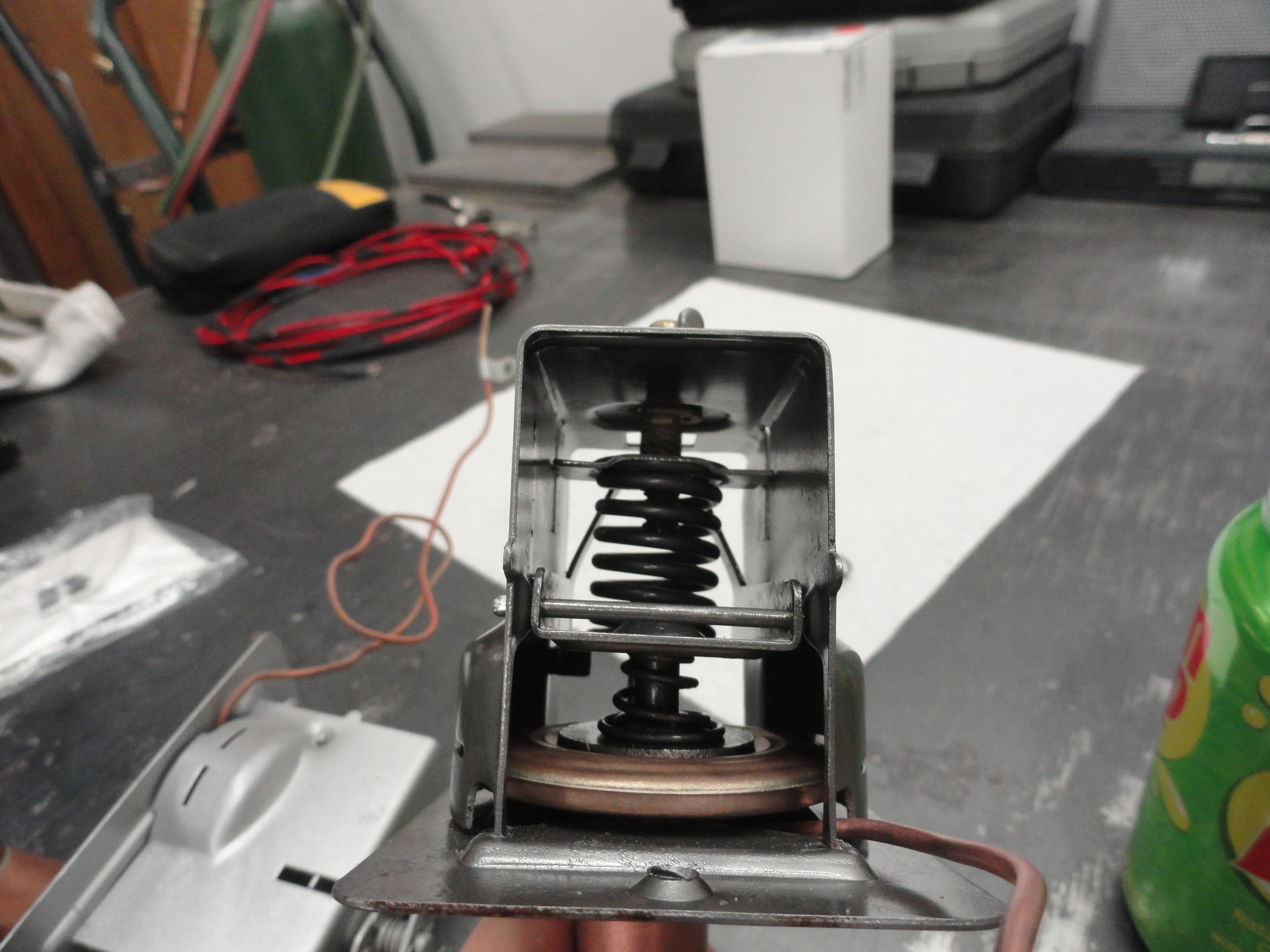
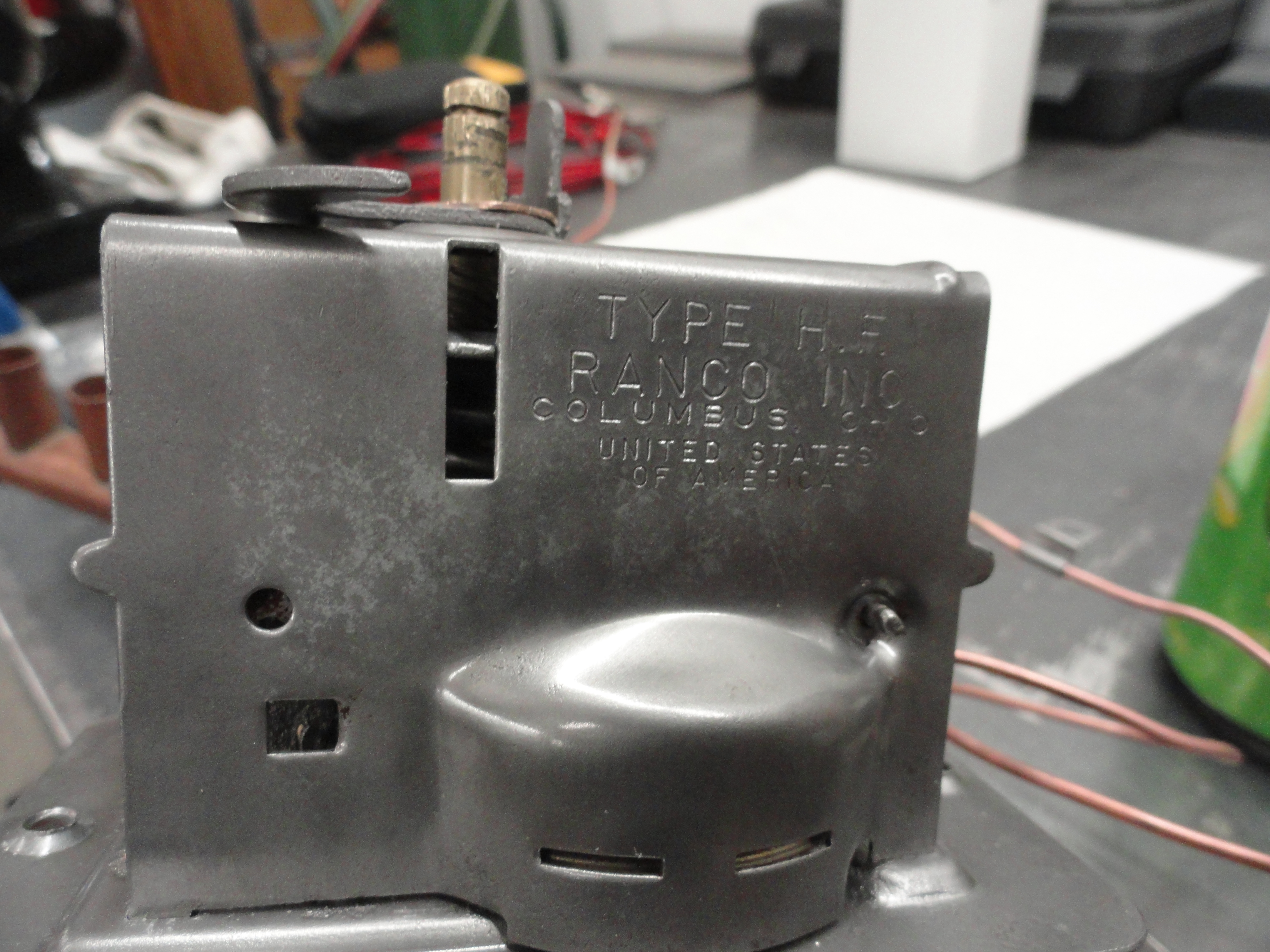
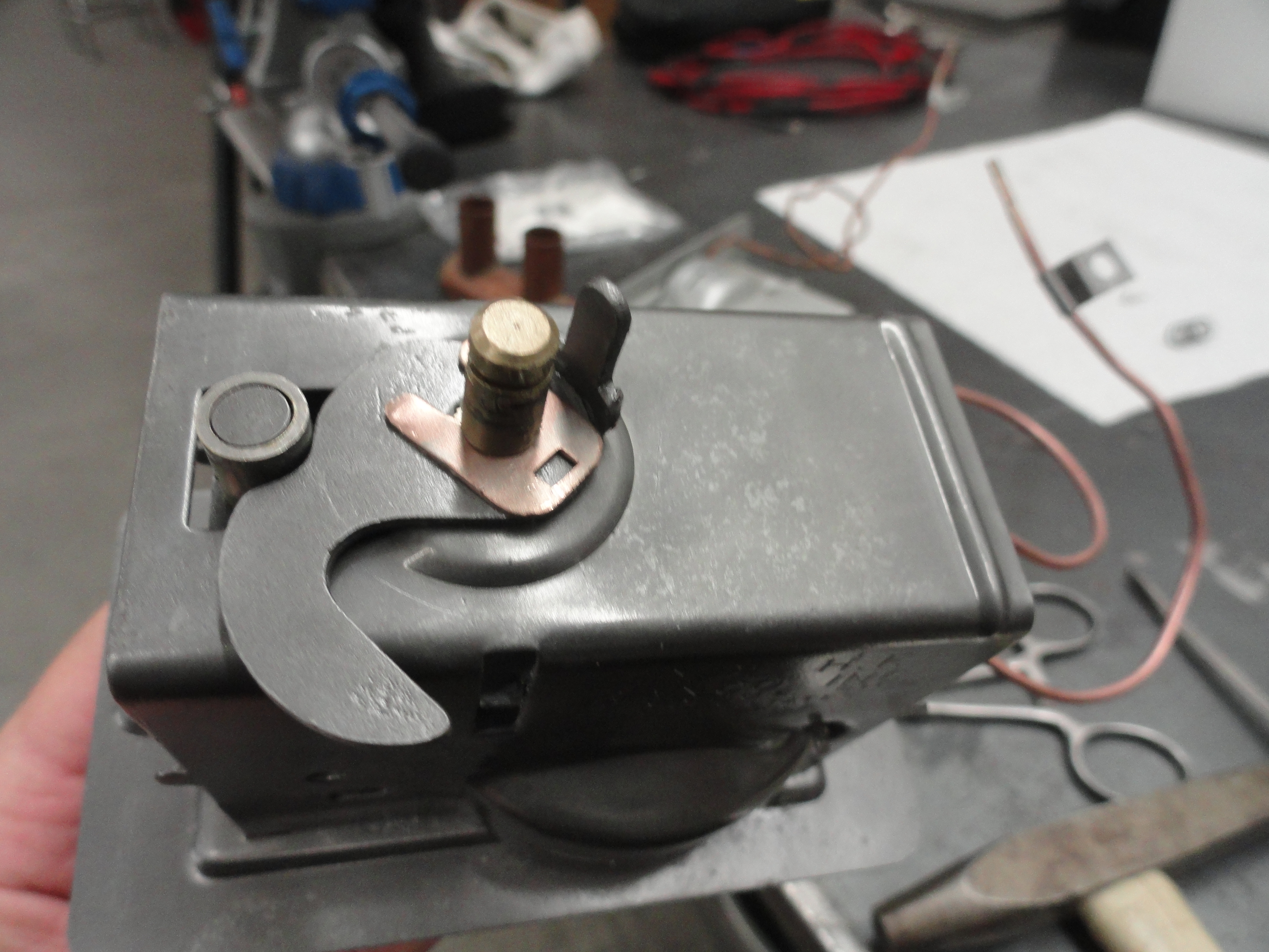
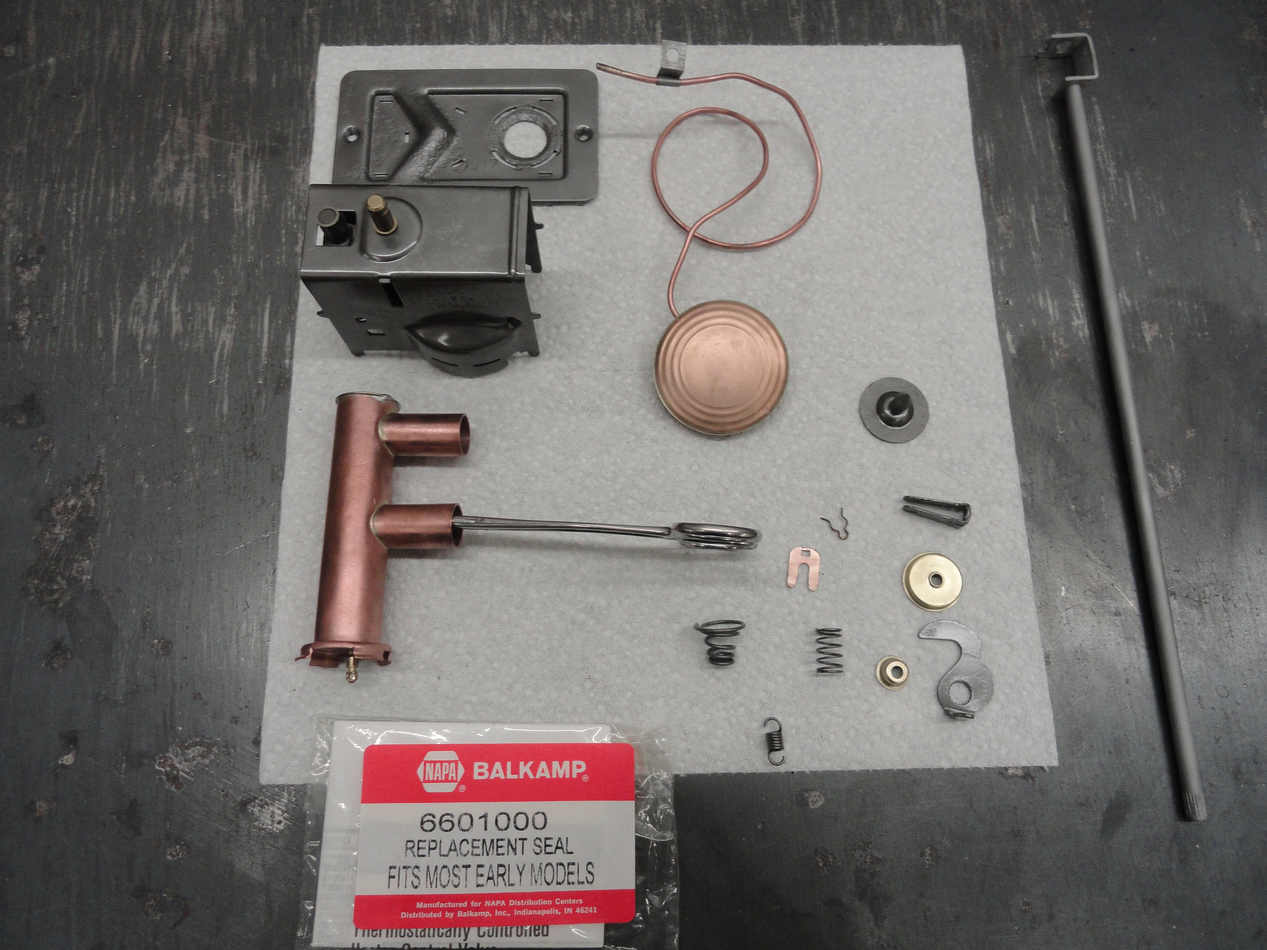
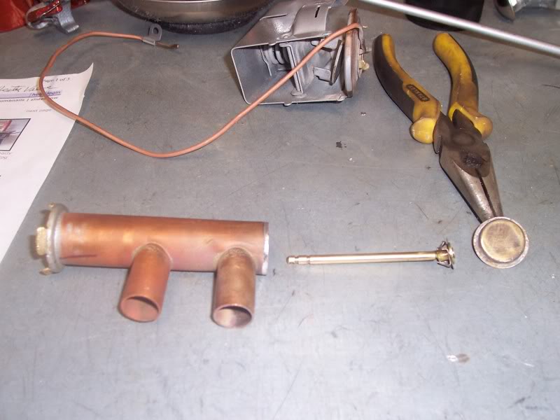
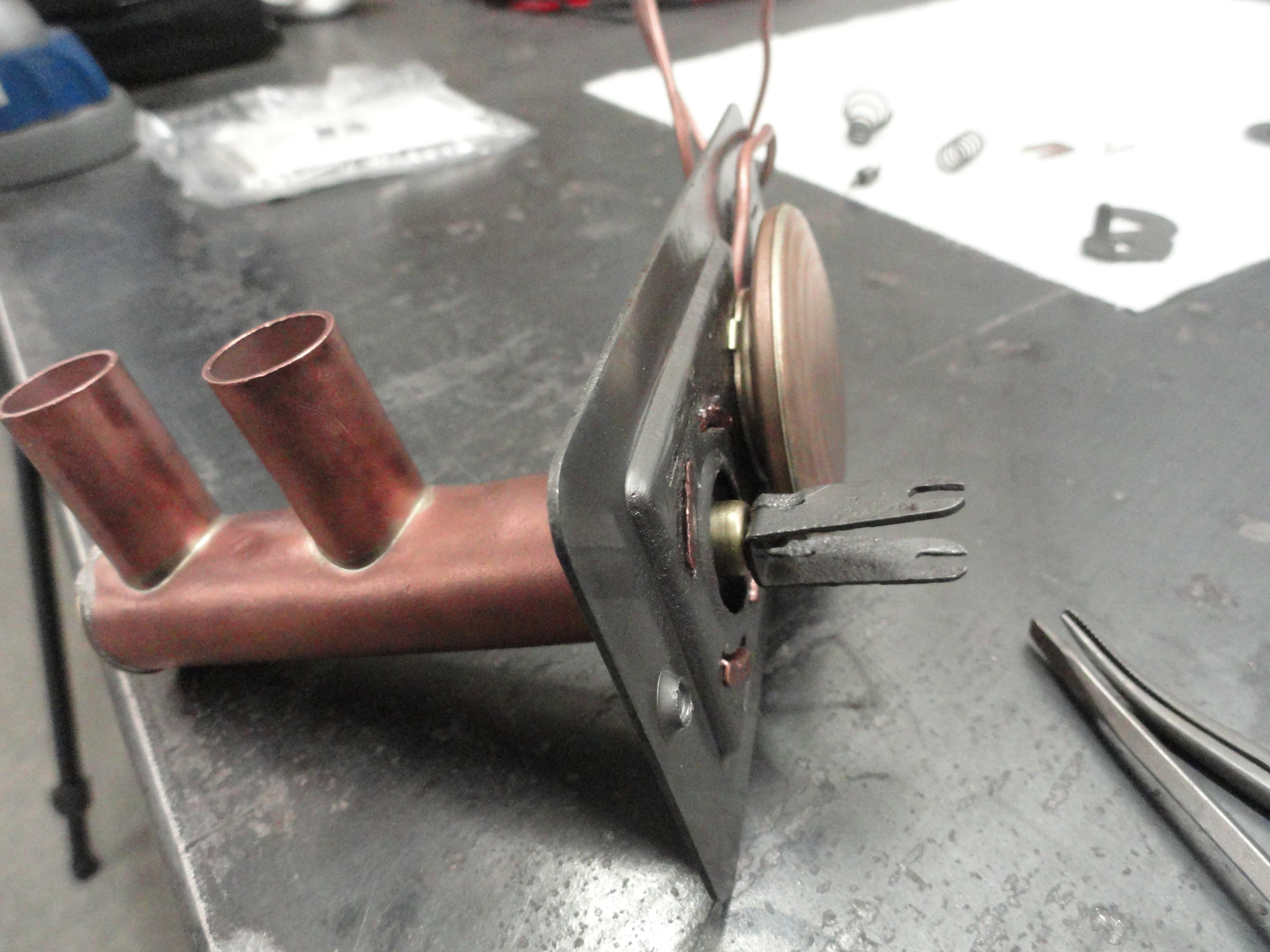
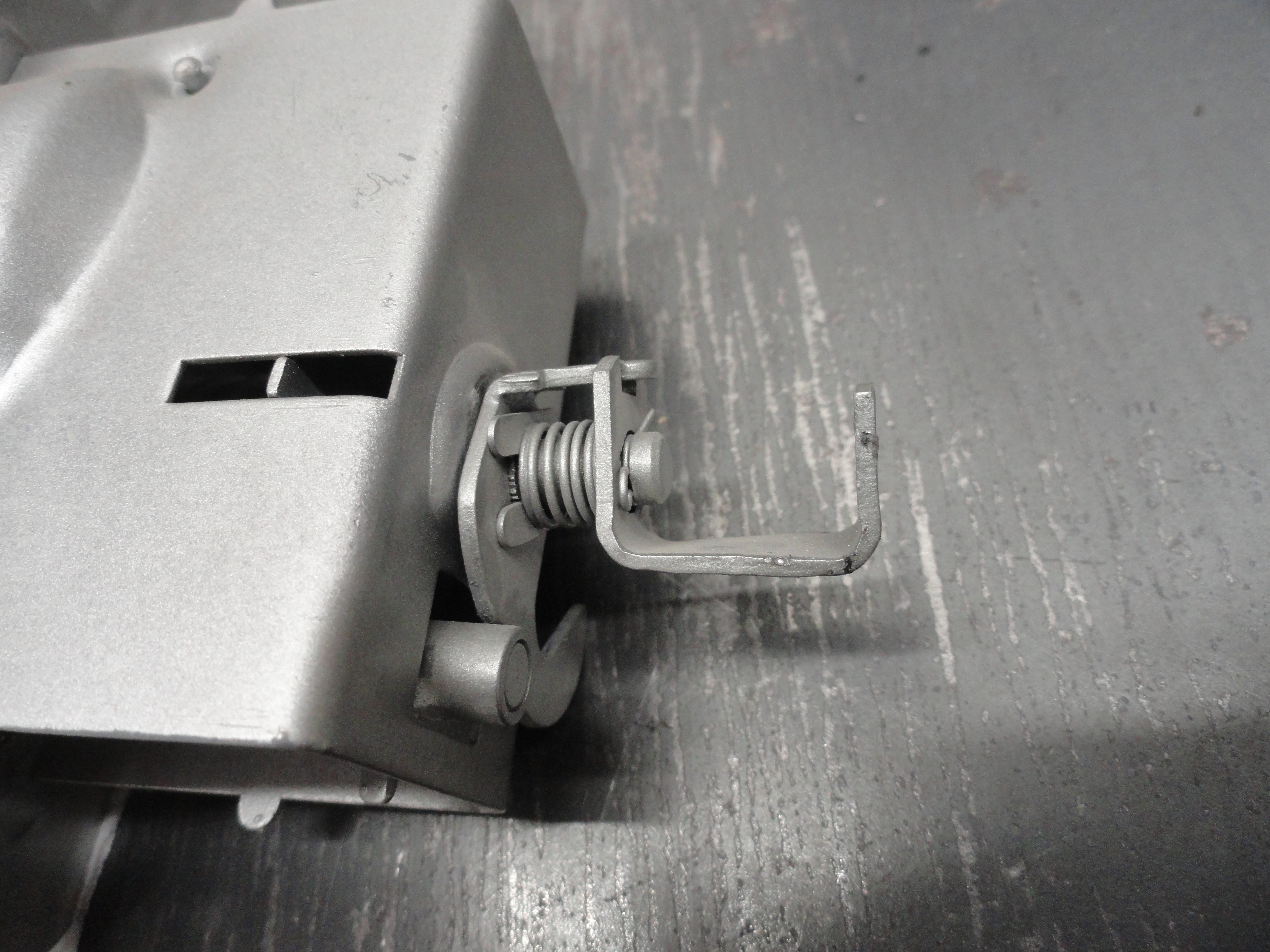
There were two slightly different styles of the Ranco Type HF Heater Control Valve. I will point out the differences as we get to them. The first thing I did was sandblast the entire unit. To properly sandblast this unit without doing any damage, use #1 Silica Sand or equivalent, set the air pressure in your blast cabinet to 40psi, and just dust it off for now. This one had cobwebs and lots of dirt and crud all caked inside making it impossible to see the internals. Always be very careful around the copper tube and bellows. If you do not have a blast cabinet, clean it like you would anything else being very careful around the copper tube and bellows. Begin by removing the Spring in the picture shown on the right. I used a pair of needle nose pliers. This is the only part that needs to be removed before we separate the case.
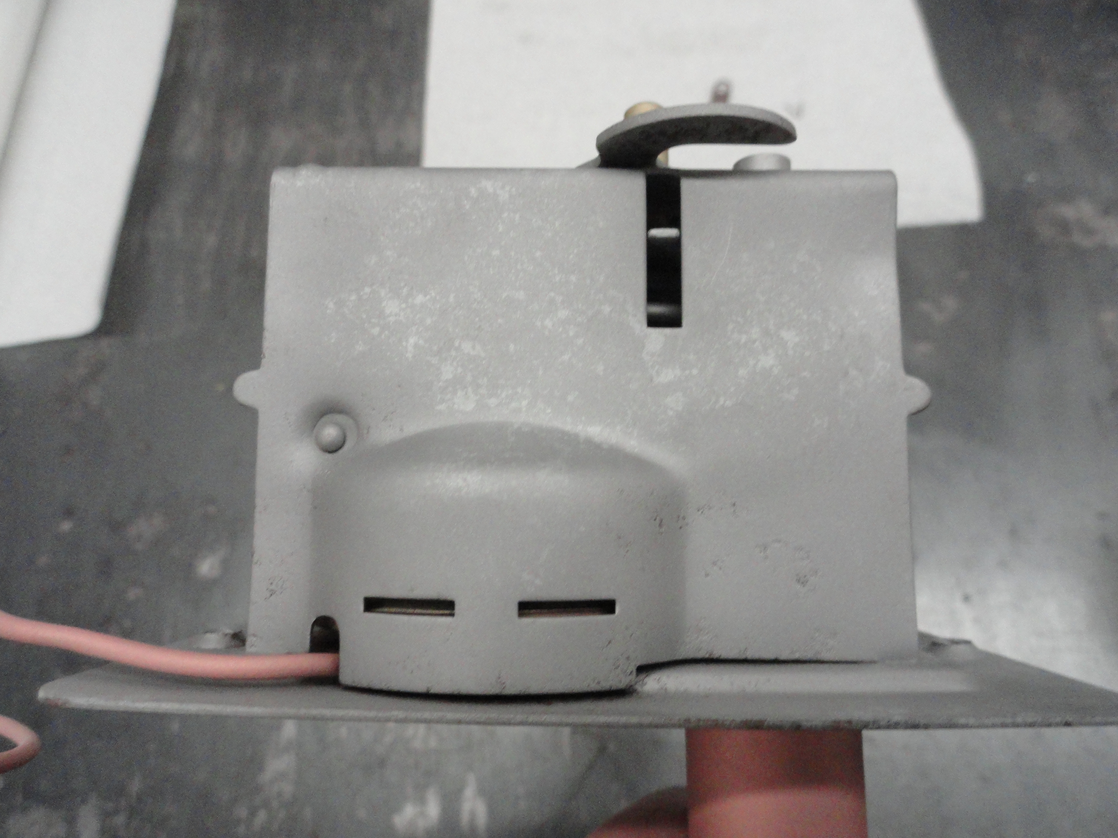
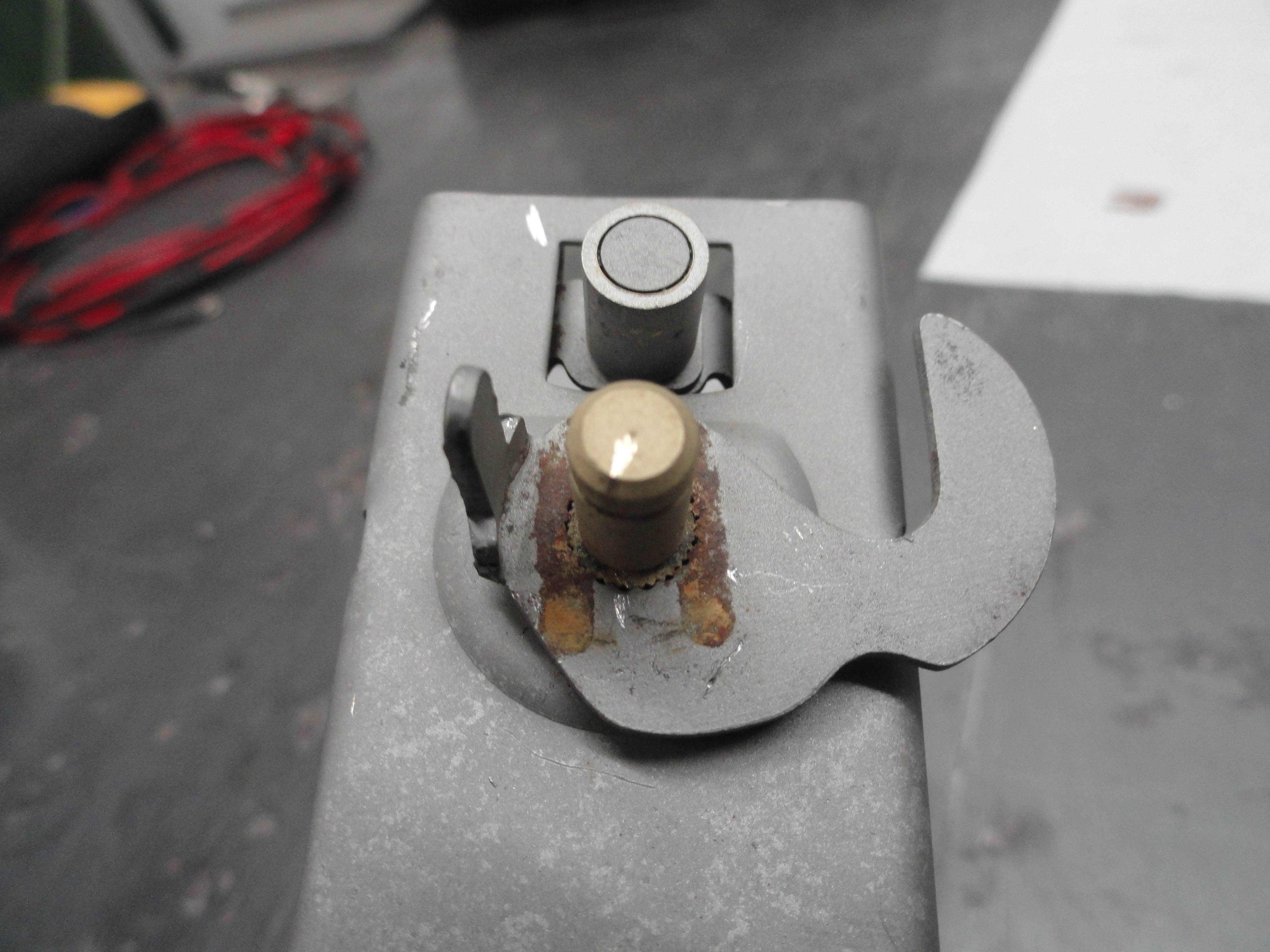
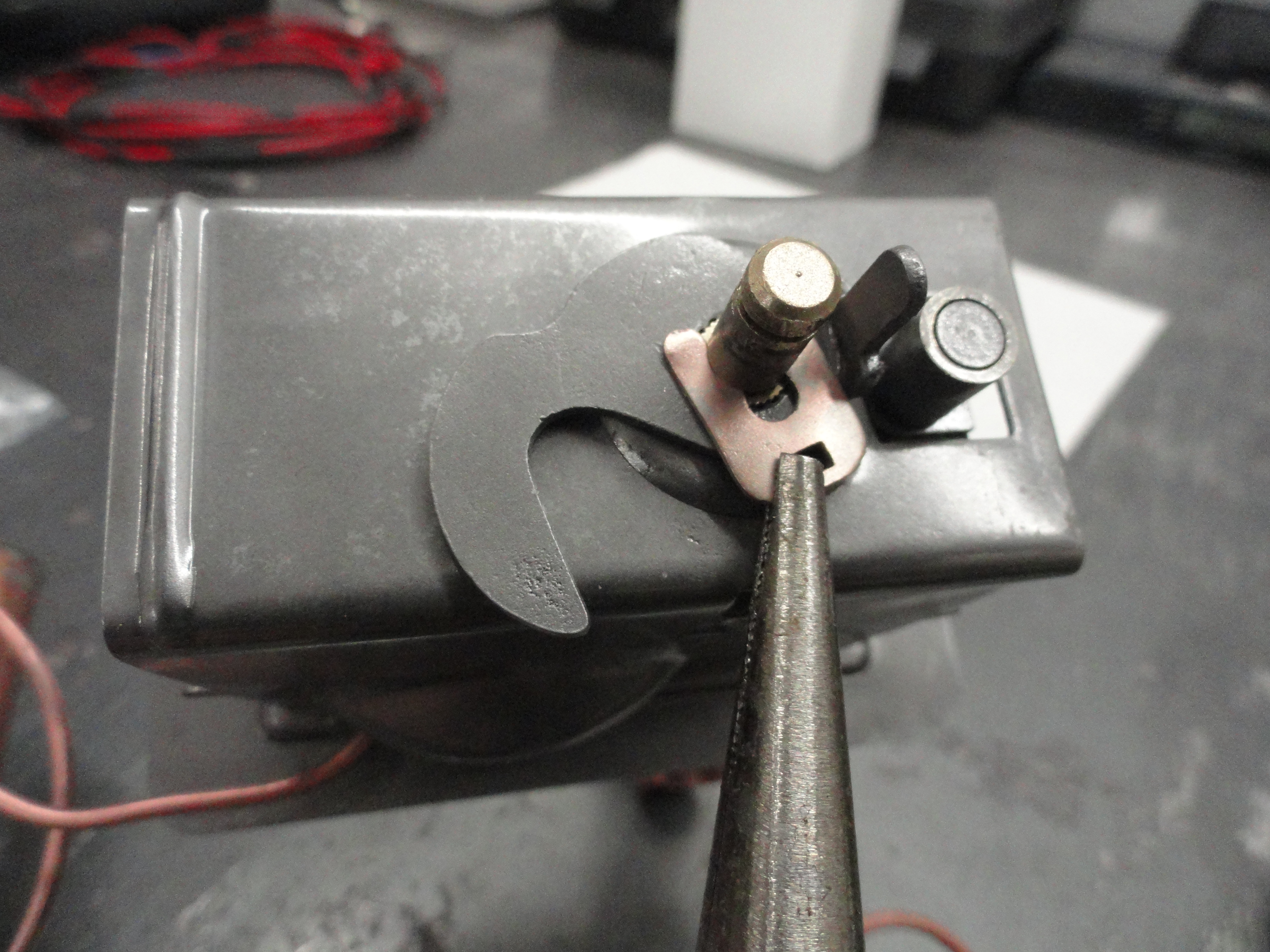
With the spring removed, turn it over to the control side and remove the clip that holds the knob control lever on. This lever is indexed and should be put back exactly where you found it. Remove the clip and the lever and blast or clean everything in that area, then put it all back together before moving on. If you choose to put it together later, mark the placement of the lever by turning the control to the stop so you know exactly where it was or mark the metal on the hub to lever contact area so that you have a mark across them. This will help you orient the parts later. Reasons for not putting it back right away include your painting process. I chose to do it later because I sandblast everything thoroughly, then run a wire brush attachment on my Dremel Tool across the metal to shine things up before Clear Coating each piece separately. The unit originally was Zinc or Cad Plated and since I feel having them re-plated is going a bit too far, Clear Coat is the next best thing.

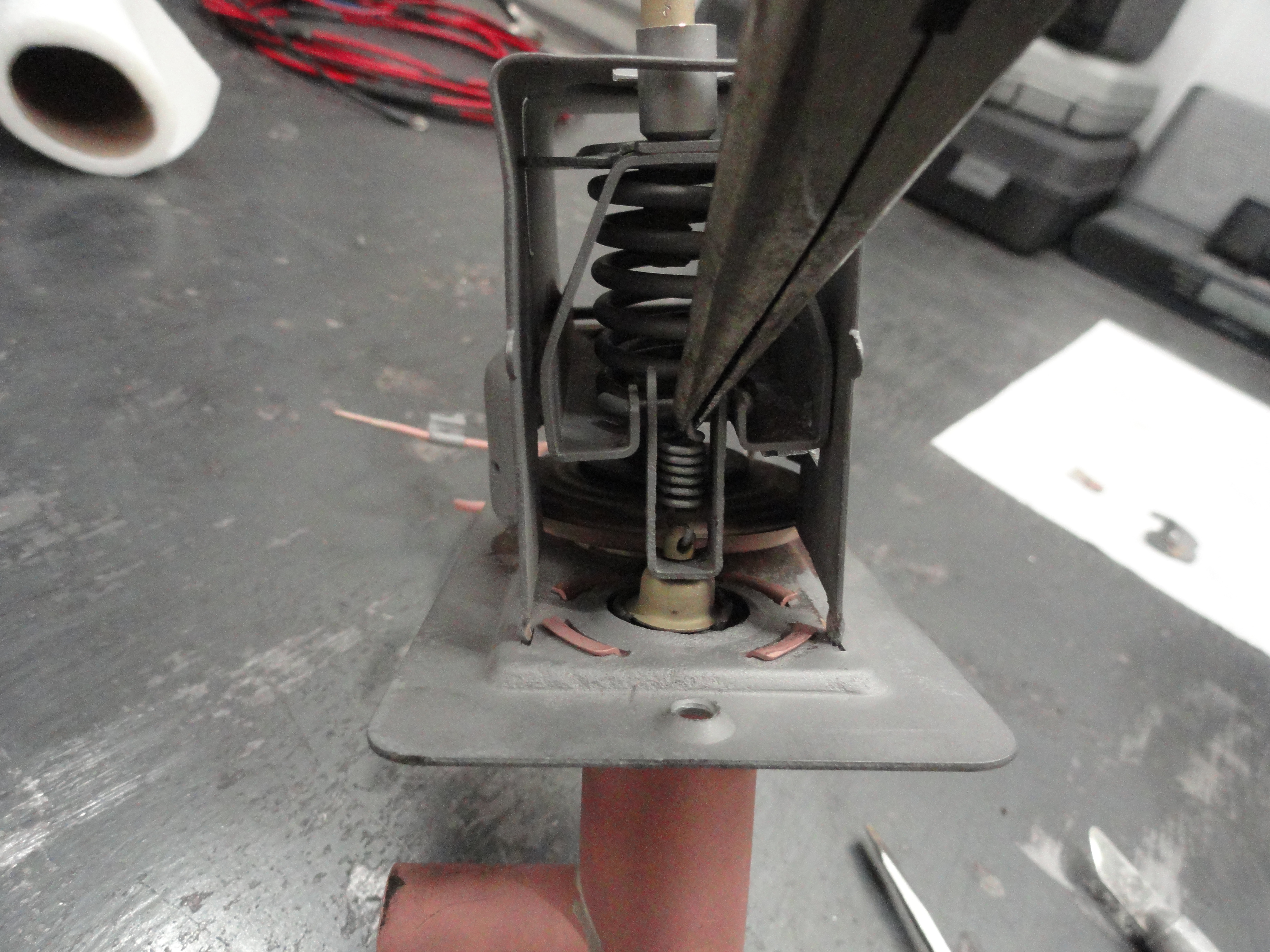
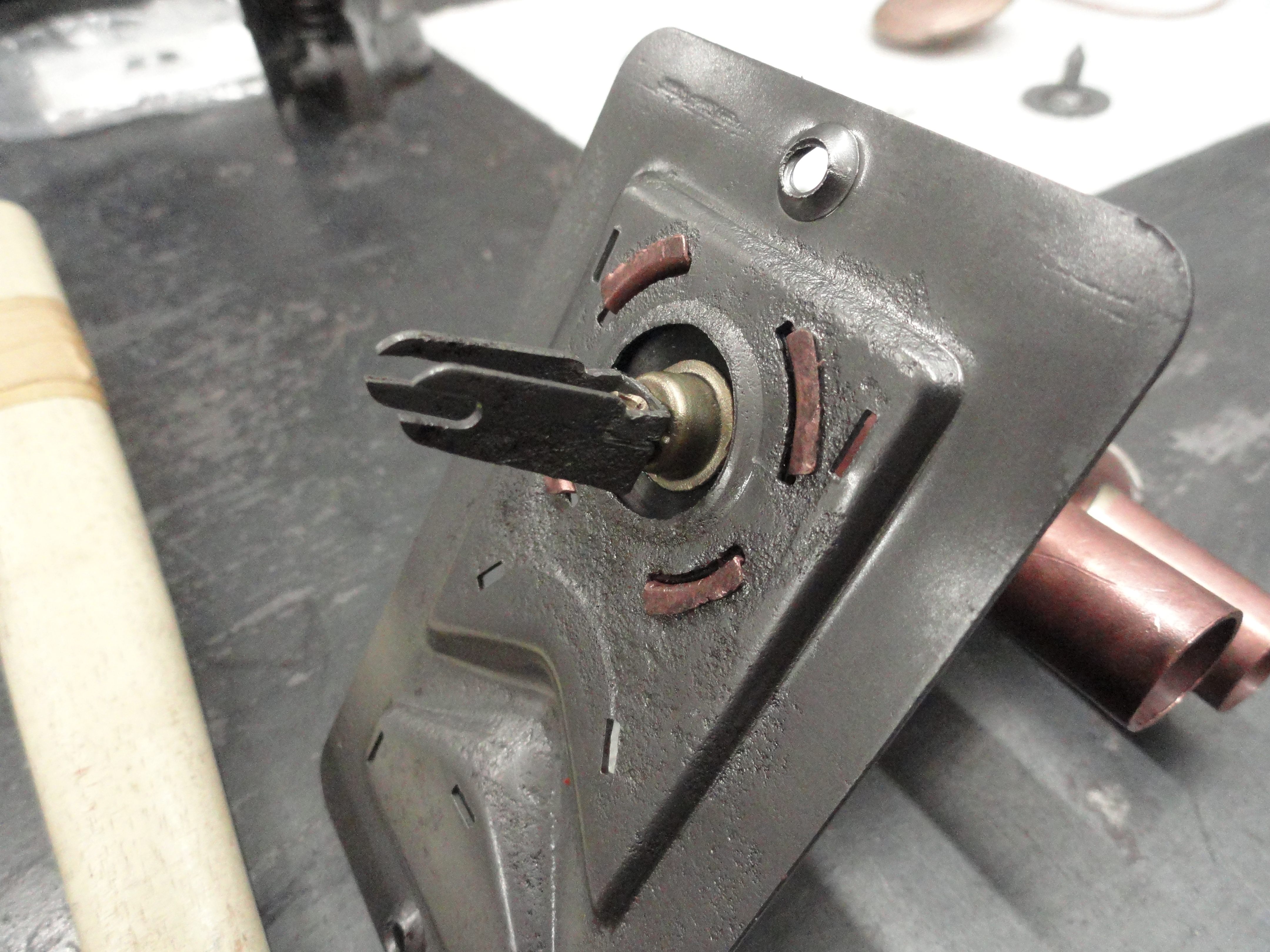
Next let's separate the plate from the rest of the assembly. This needs to be done VERY carefully and extra patience is needed. You do not want to break off these tabs much less make them weaker. There is quite a bit of force on these tabs and you will want them to be strong when you bend them back down later. Start with the easy ones, the three brass tabs holding the bellows in place. Very carefully wedge an Exact-o knife in under the tab and carefully lift it enough to get the next thicker putty knife blade, very small screwdriver, whatever you need to slowly and carefully bend them up just enough to get the bellows loose. Move on to the four corner tabs and do the same thing. The corner ones are under pressure and will want to pop out once they are sufficiently free. Once free, the parts (to the right) should be what you have as well. The larger spring and wire clip are what holds the "Warmer" knob on. Your bellows compressor spring and plate may look different depending on your model. Some of them only have a bellows compressor and no spring. That is normal too. If you do have that kind, remember the orientation for assembly.
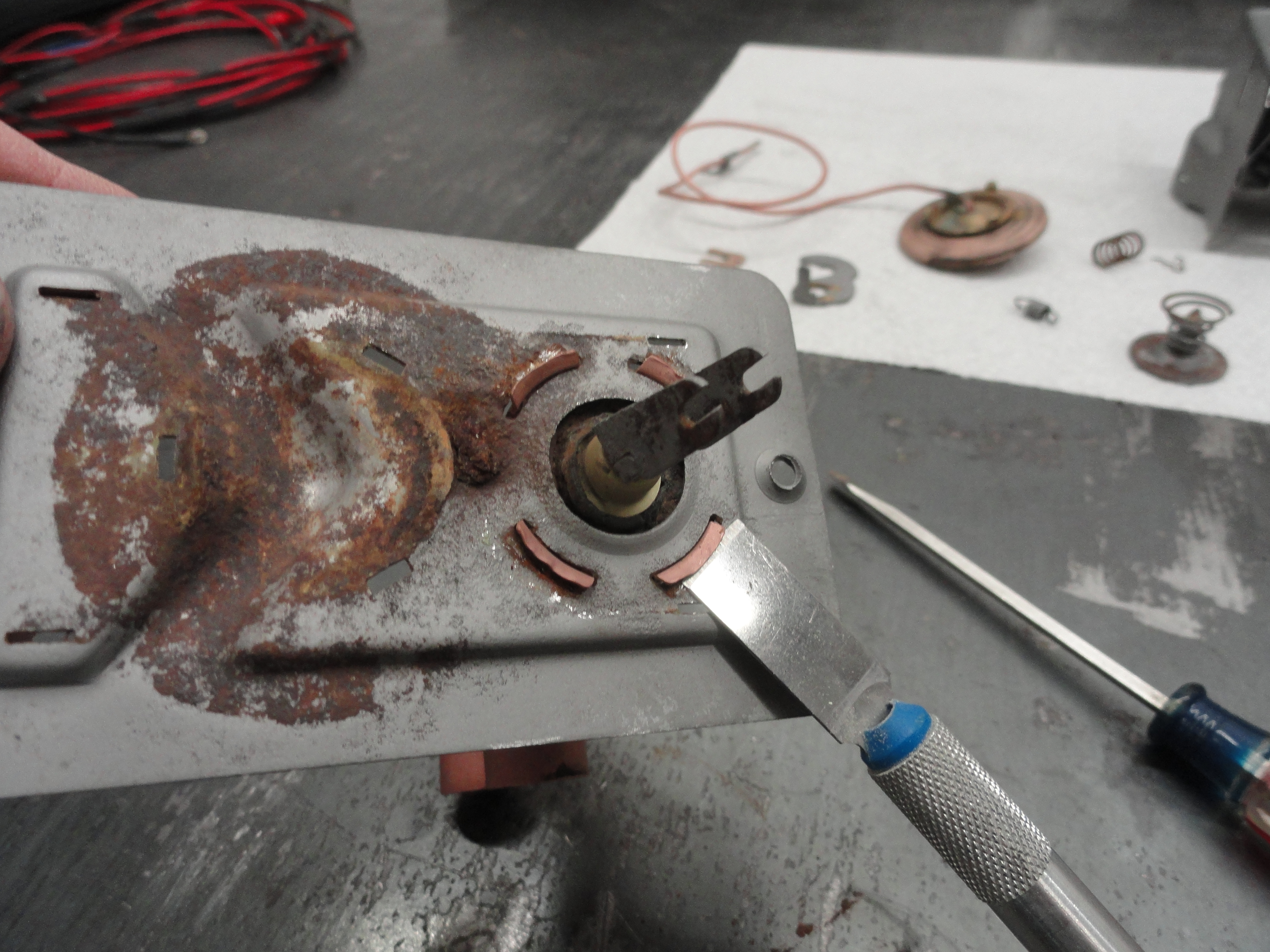
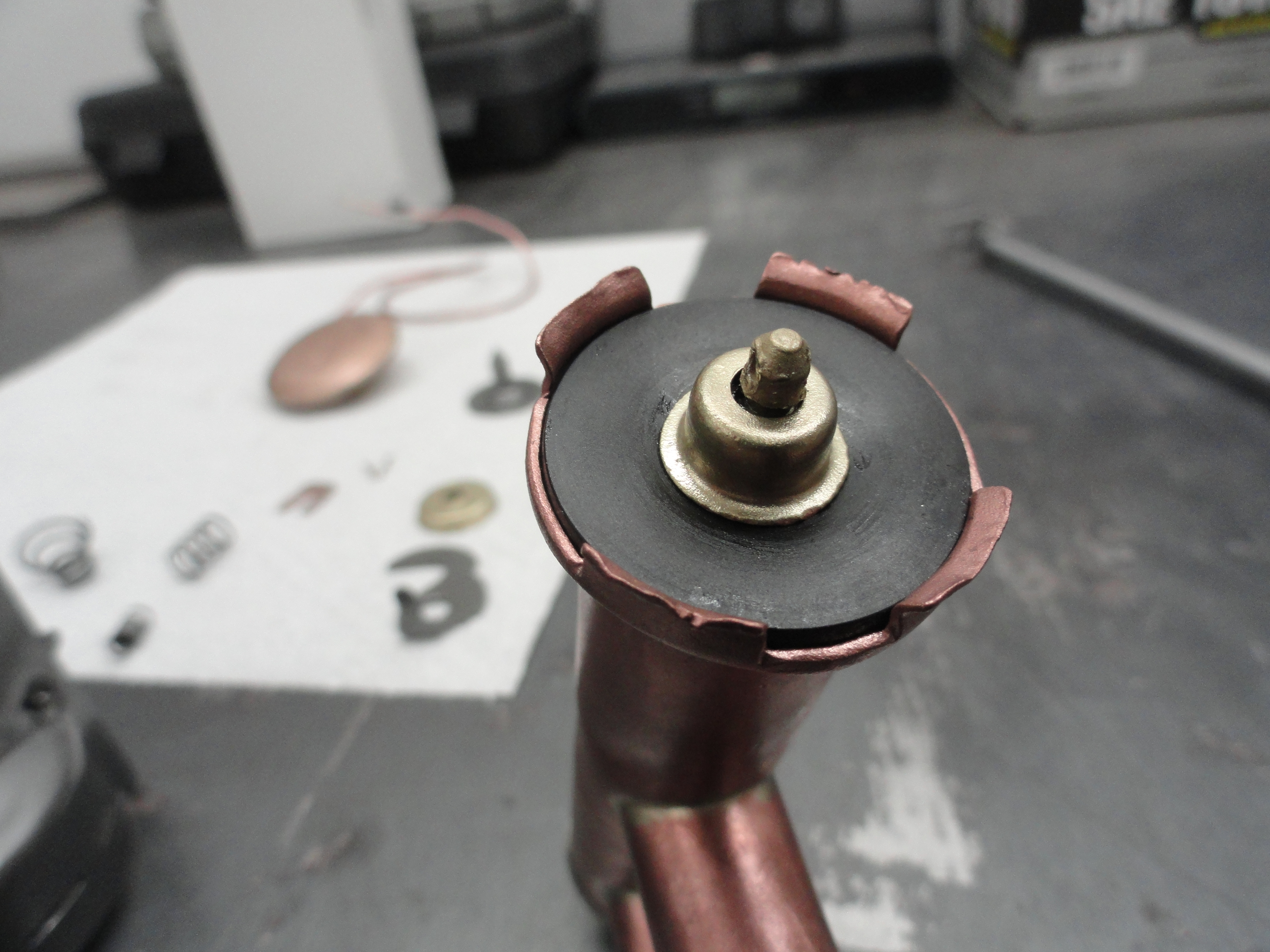
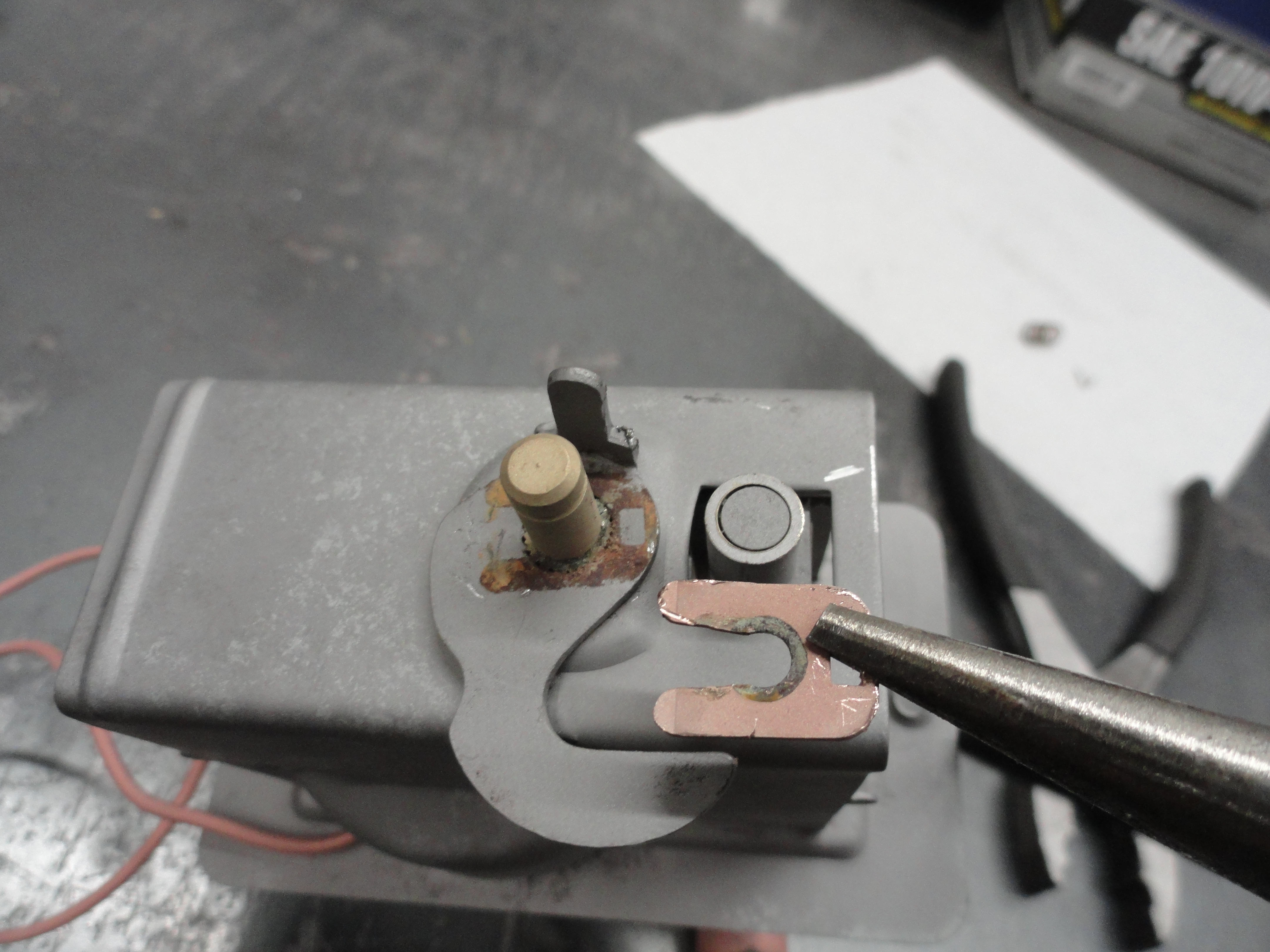
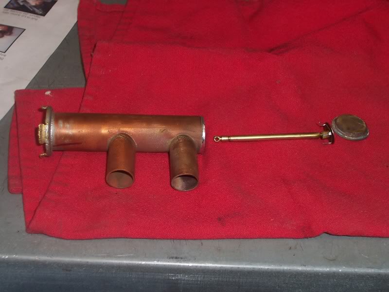
With most of it apart, we need to remove the large copper tube from the faceplate. This is necessary to replace the rubber washer that is the only disposable part of this Valve. This is getting to be a rather rare part so be careful with your new "Repair Kit". The part number of the rubber washer with the steel ring around it is Balkamp 6601000 and was available at NAPA and most of our vendors last time I checked. Very carefully bend the tabs up on the plate enough for the tube to come out. You want to take special care not to bend this assembly because it will cause the seal to leak. Put pressure only on the tabs. I find a small screwdriver jabbed into the slot keeps the copper underneath from bending away and causing that damage. The pictured rubber seal is not serviceable and commonly what you see when taking these things apart.
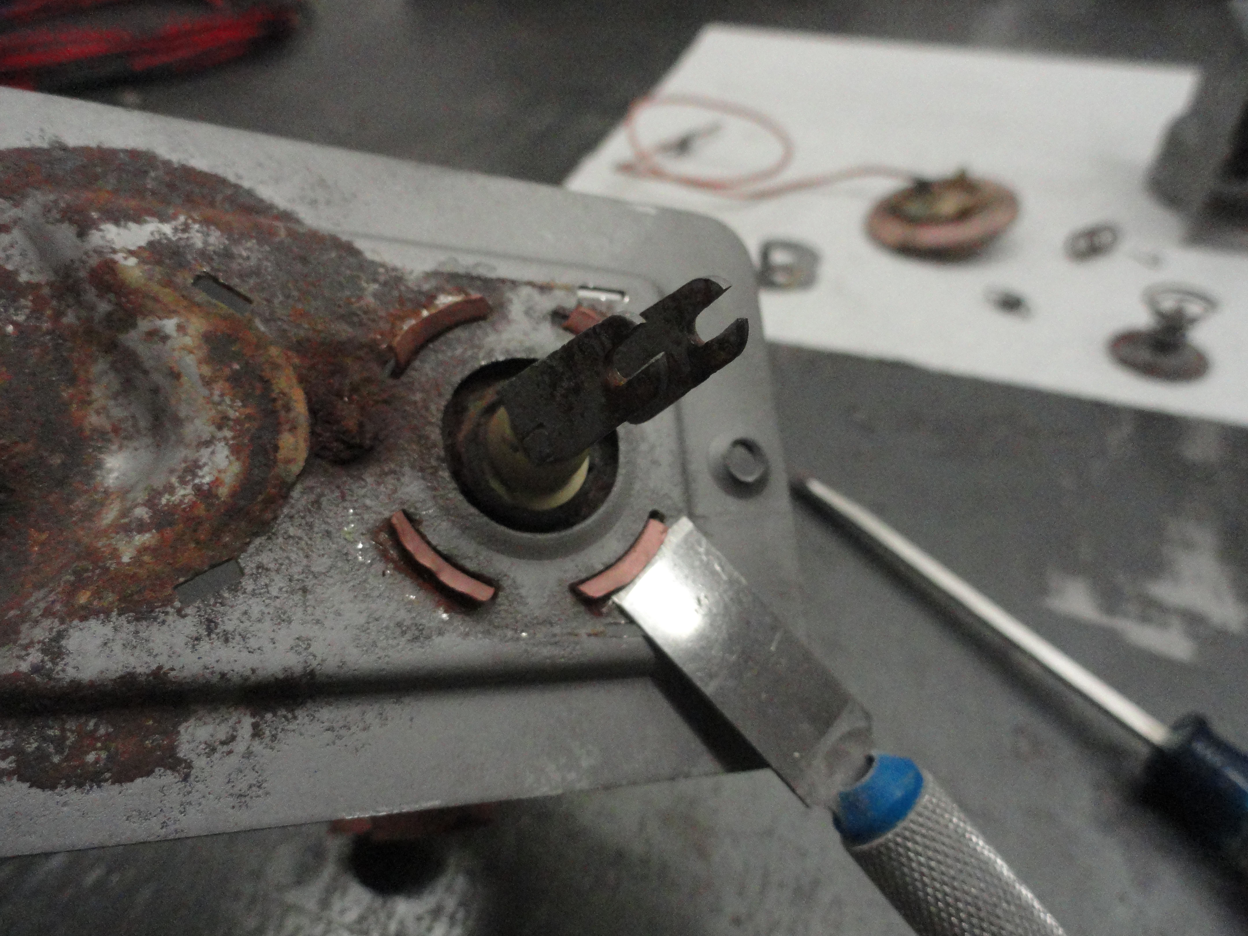
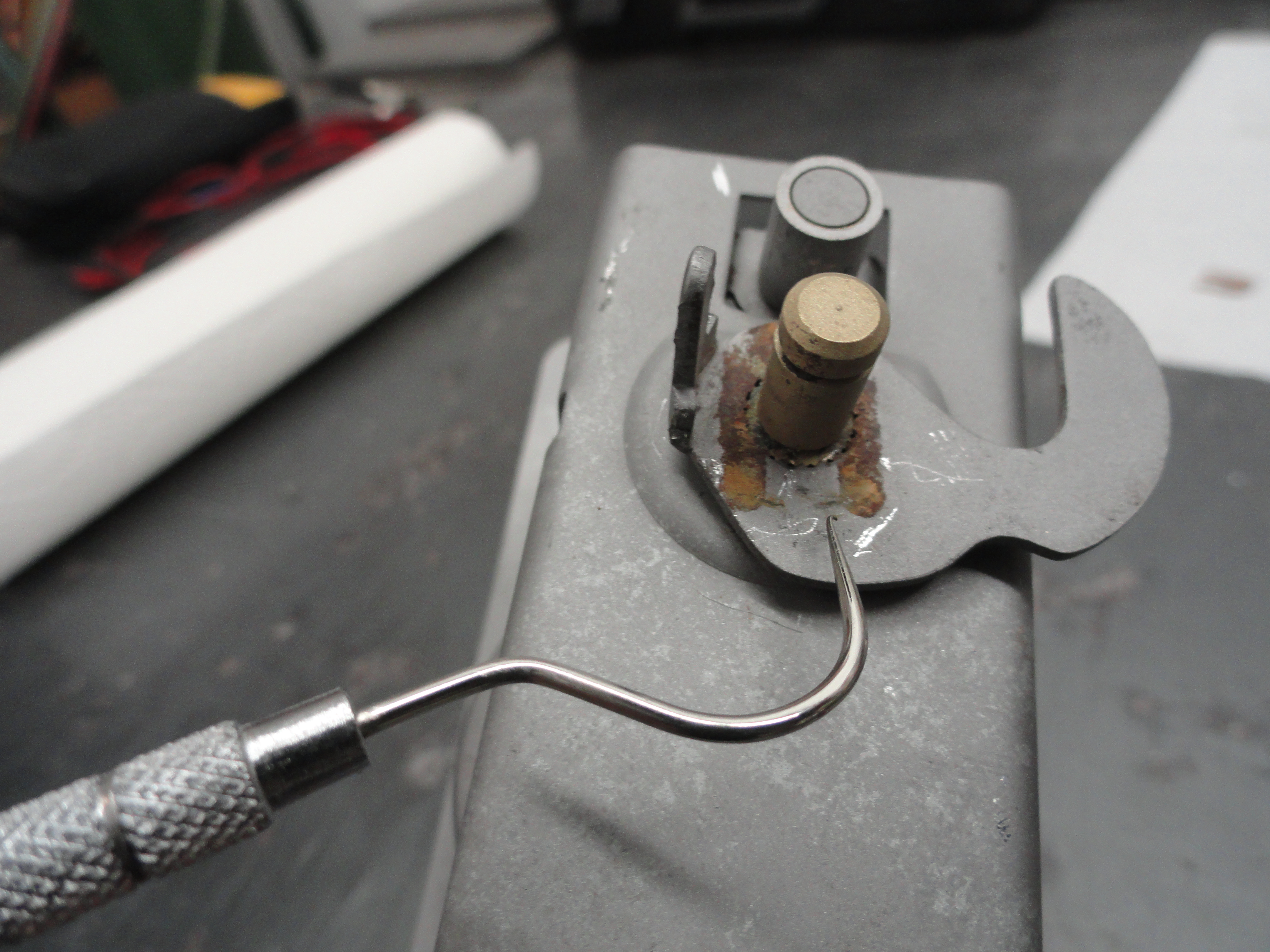
Remove the clip with the slots in it (left) by using a very thin blade to pry it apart enough to get the shaft to come loose. This is not an easy task, but take it slow and you can do it. Remove the small copper bell and set it aside. Clean the remaining 'rubber' seal out of its place. Depending on the model of your valve, there may or may not be another copper cap that comes out after this (right). Some Valves came with this piece soldered on. If you have one like the one shown, removing it you will be able to clean the inside of the tube out better. Also, it's nice to ensure the small tines on the far end of the shaft (hard to see) are straight and the far end cap on the shaft seats properly. If it REALLY bothers you that you can't see inside the tube, the end cap is soldered on with regular solder used in plumbing copper pipes. Heat with a propane torch until it comes loose. I didn't find it necessary because of the model I am doing having the removable closure.

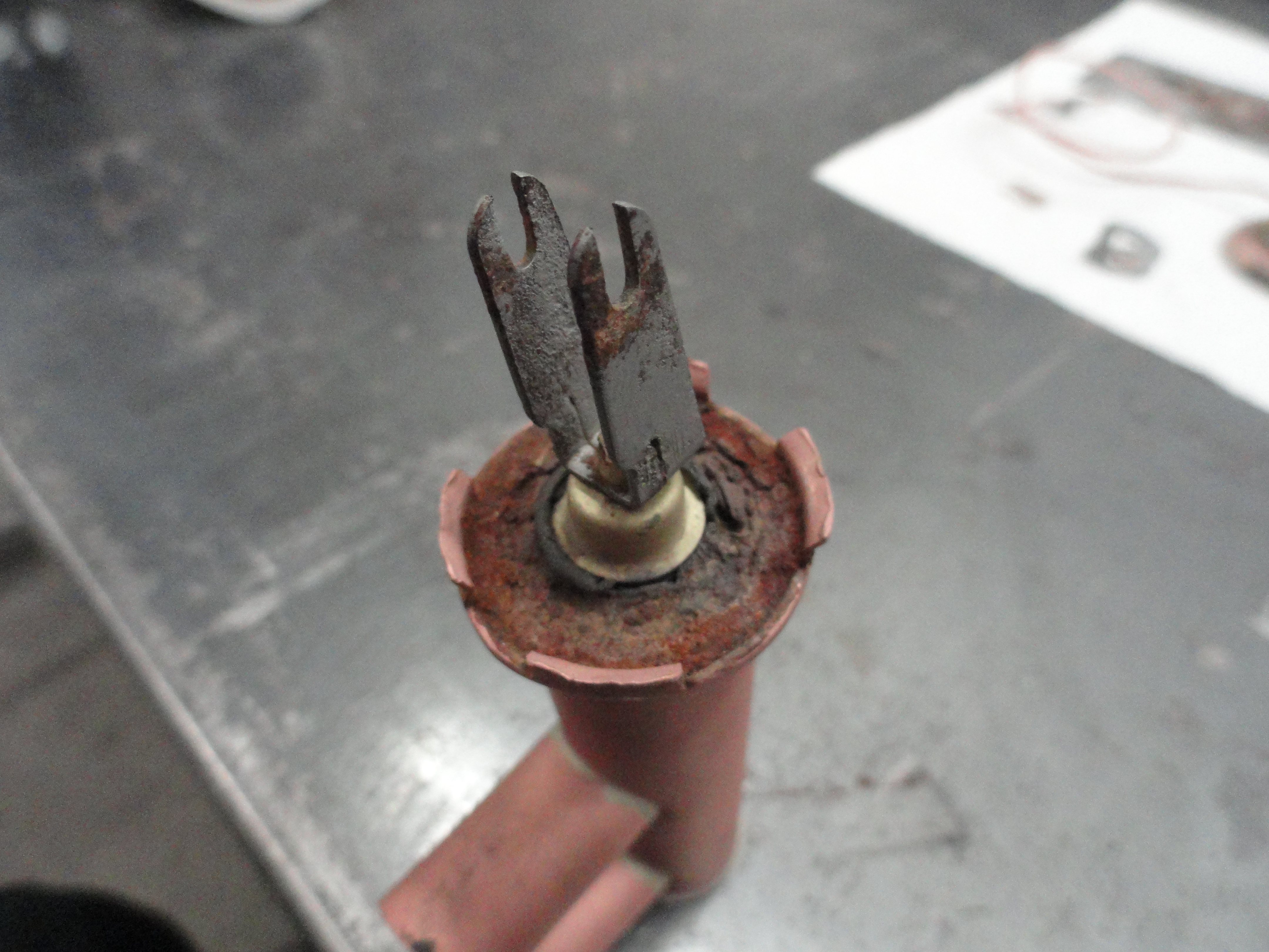
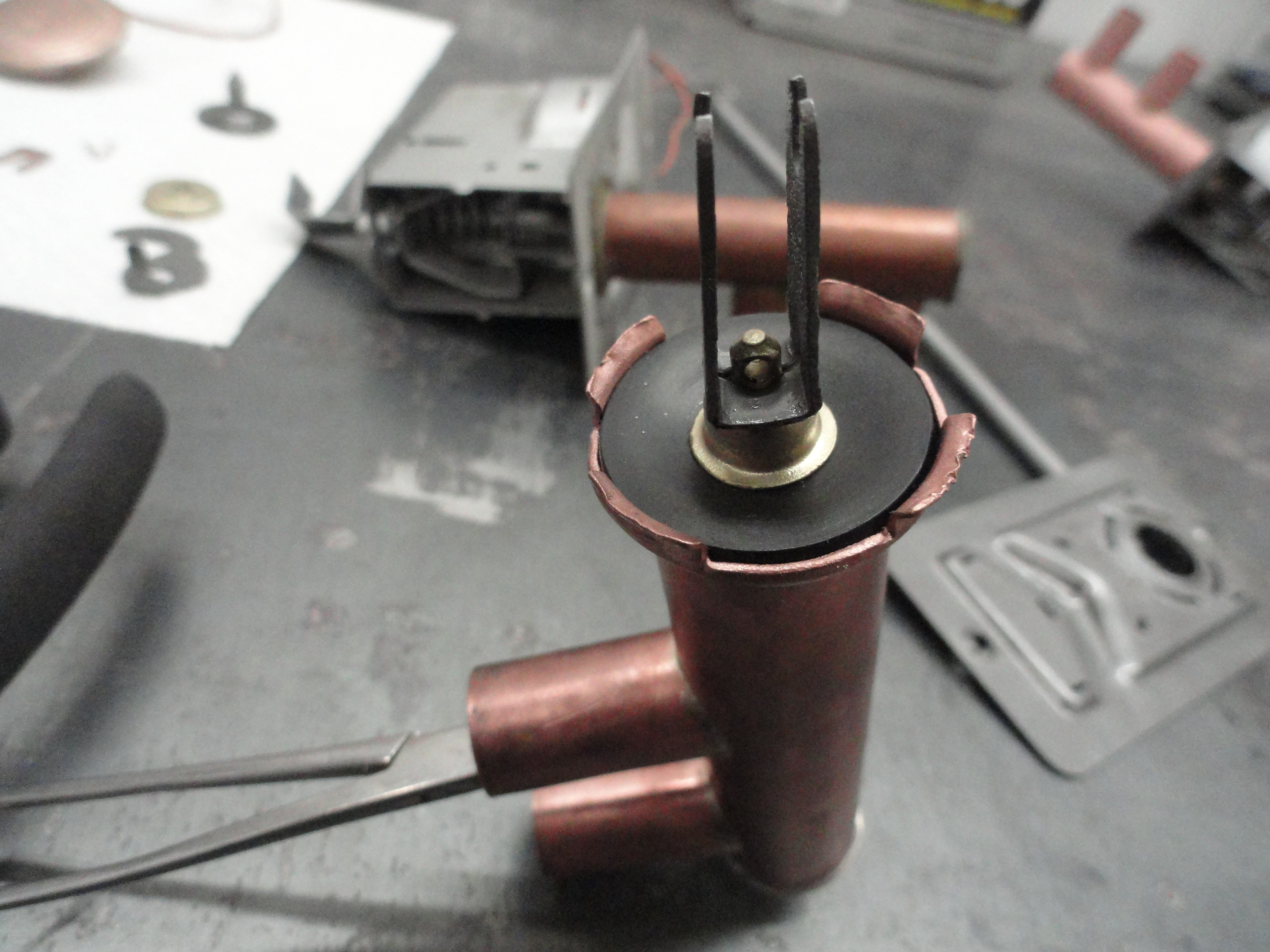
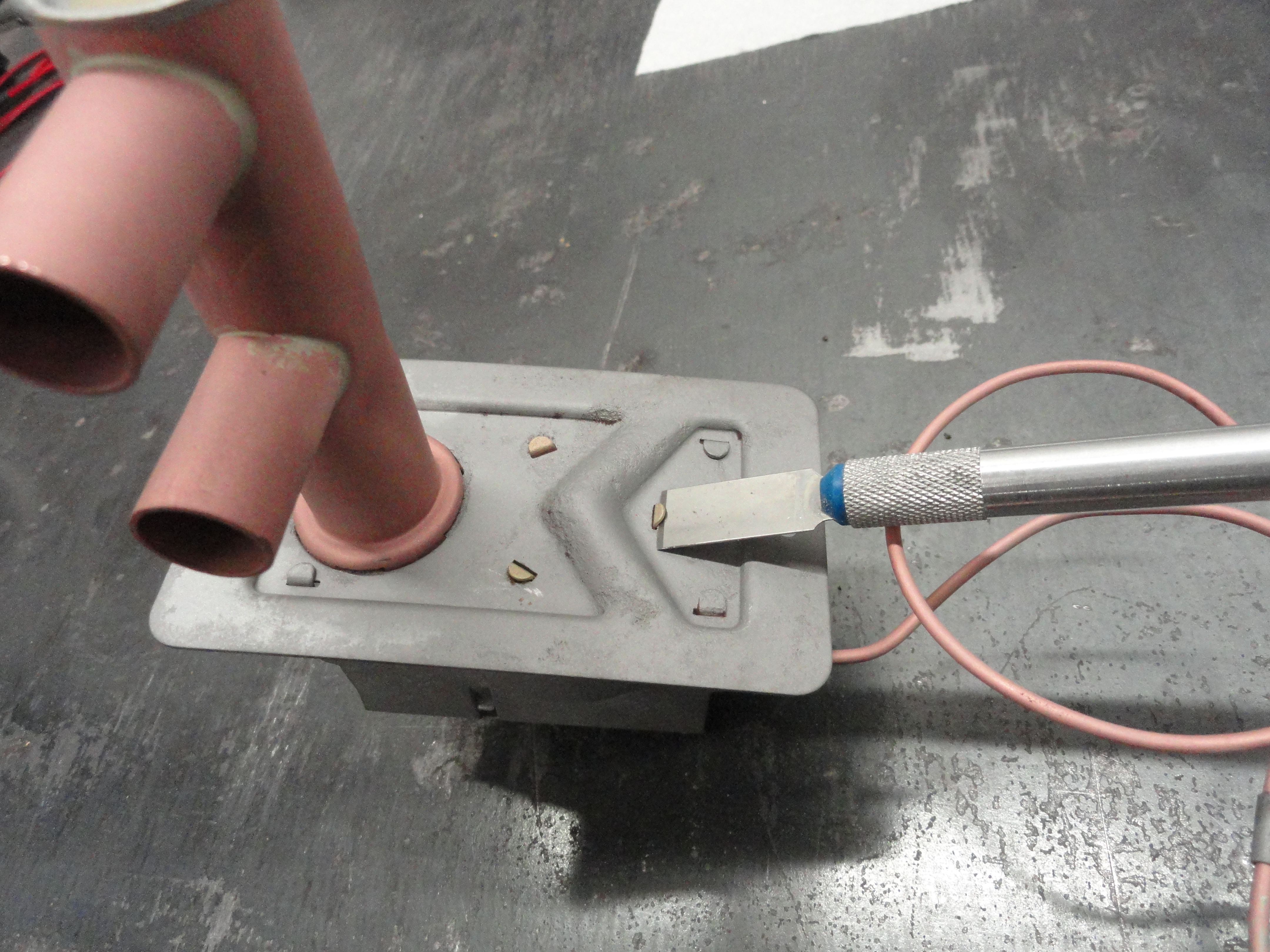
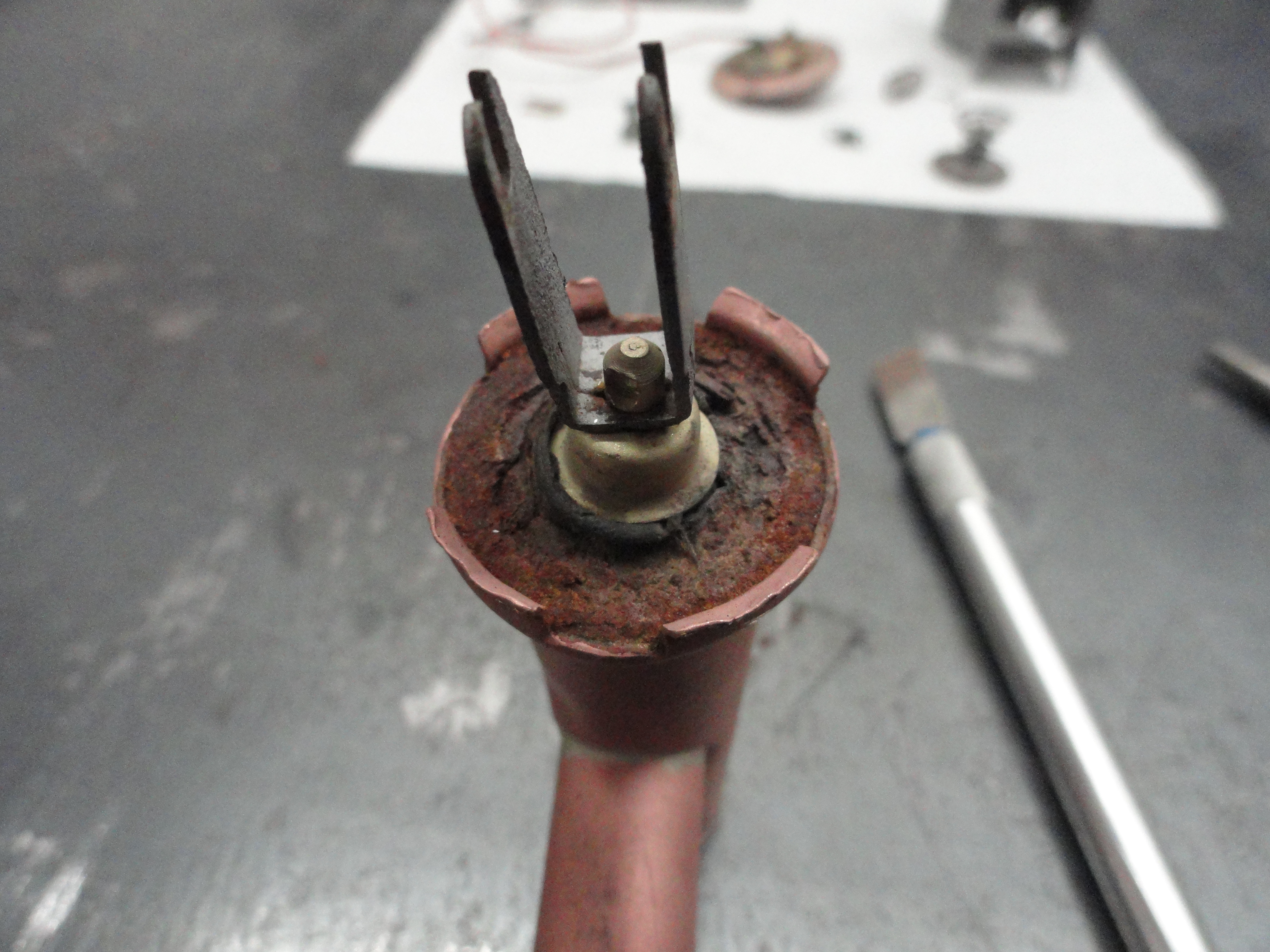
Before installing the seal, we need to ensure the shaft and shaft end on the inside travels up and down nicely while staying centered on the
hole. Inside where you can't see very well is an end cap (on the shaft) with 4 tines on it that face towards the seal. They must all be on the
inside of the hole thus centering the shaft at that end. They are only about 1/8" deep so move the shaft around in the hole until everything
feels centered and aligned properly. If any of the 4 tines are bent they must be straightened to go inside. Once you do this, take a pair of
hemostats and hold the shaft as tight to the rubber seal end as possible while the shaft is perfectly centered. (shown left and right).
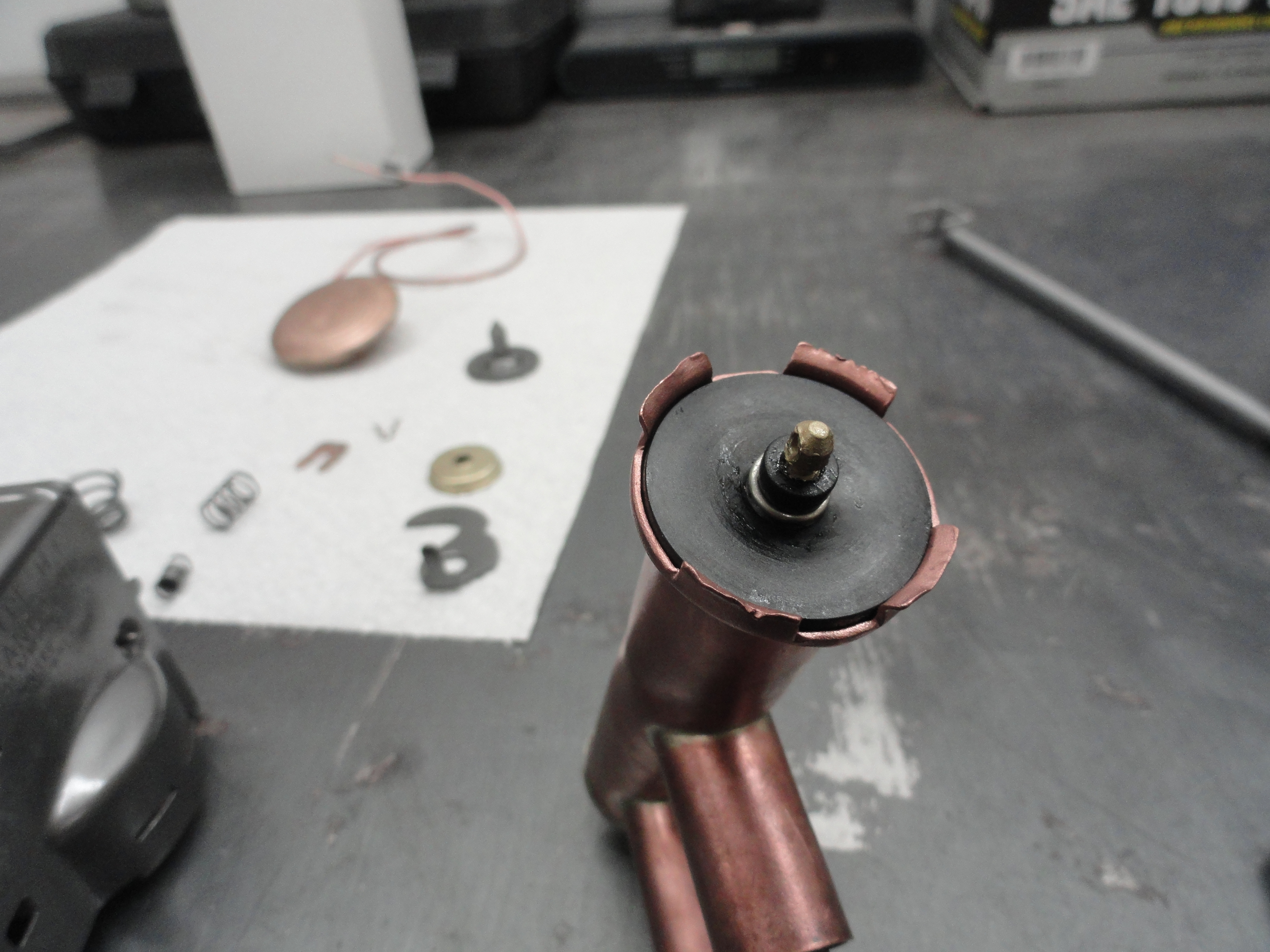
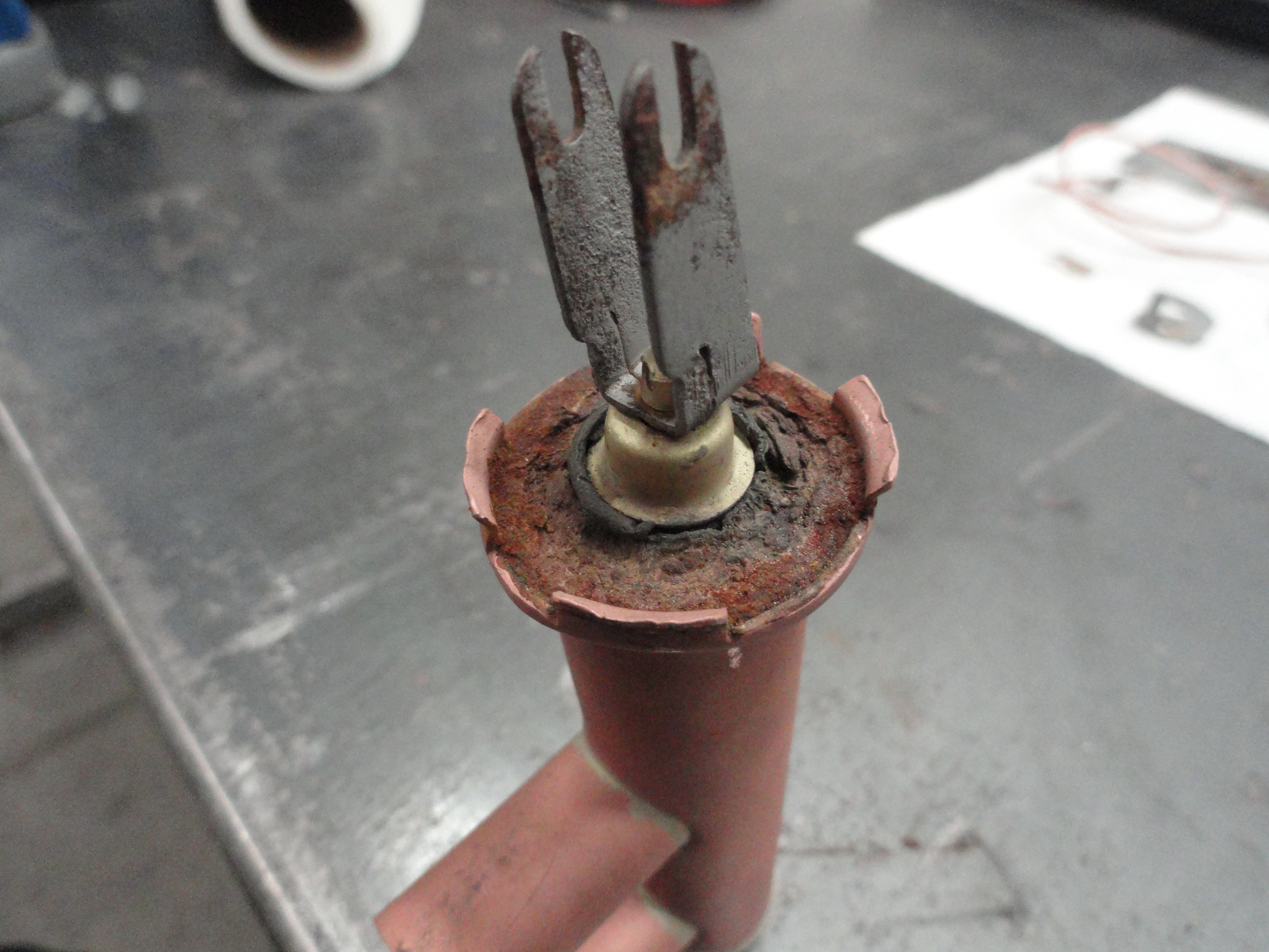
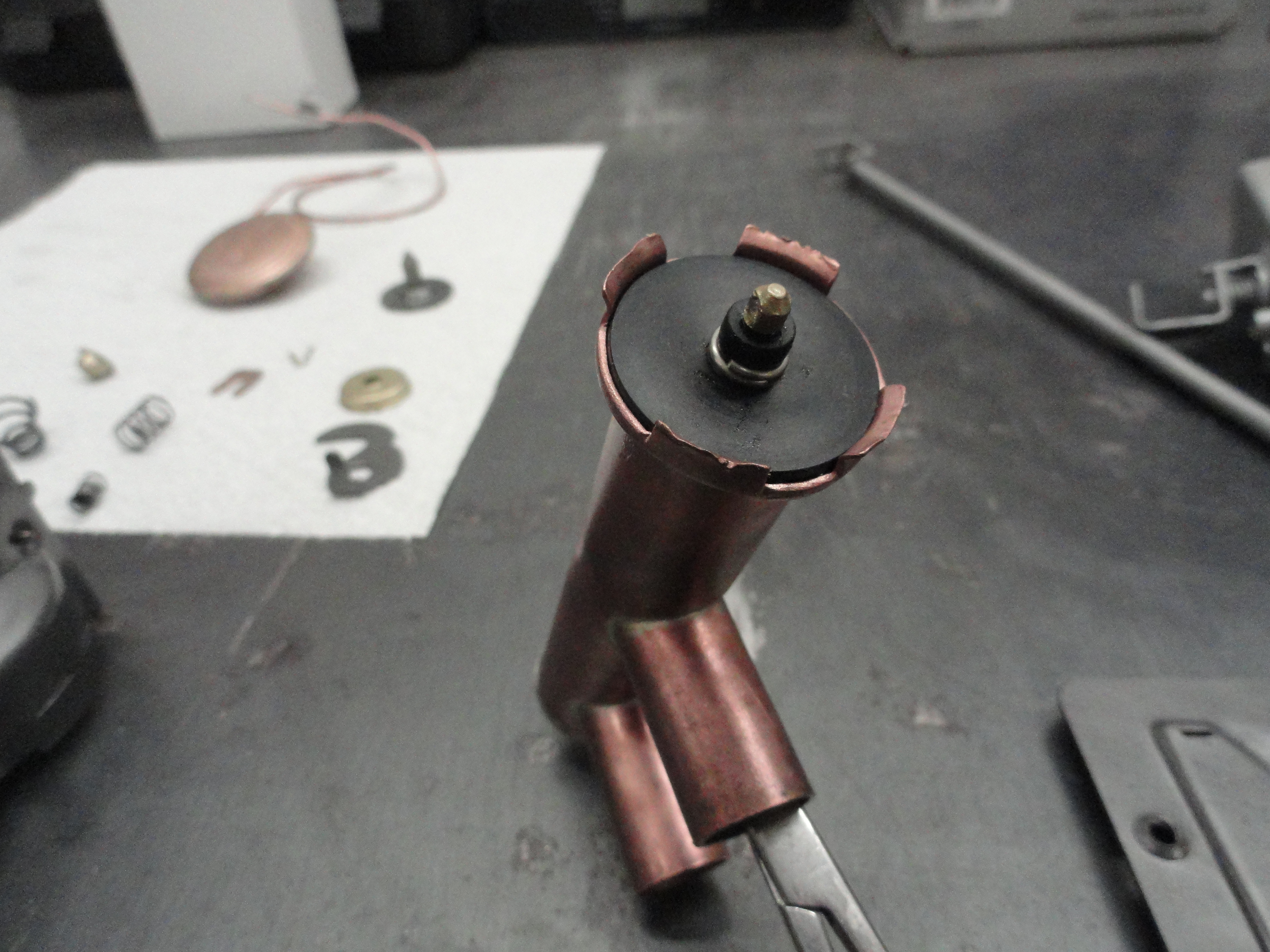
Here are a few bonus pictures from my good friends Alvin and Denny. As you can see by these pictures, the shaft has the round closure with the
tines. This needs to be perfectly centered and resting on its ledge inside the tube, then clamped tight so it doesn't move when installing the
new seal. This information is much appreciated because Alvin took the end cap off which is something that I didn't do and Denny got a closer
shot of the inside. Between these pictures and mine, you should have a clear idea of how it works, but if you have questions, there is always
email deve@speedprint.com.
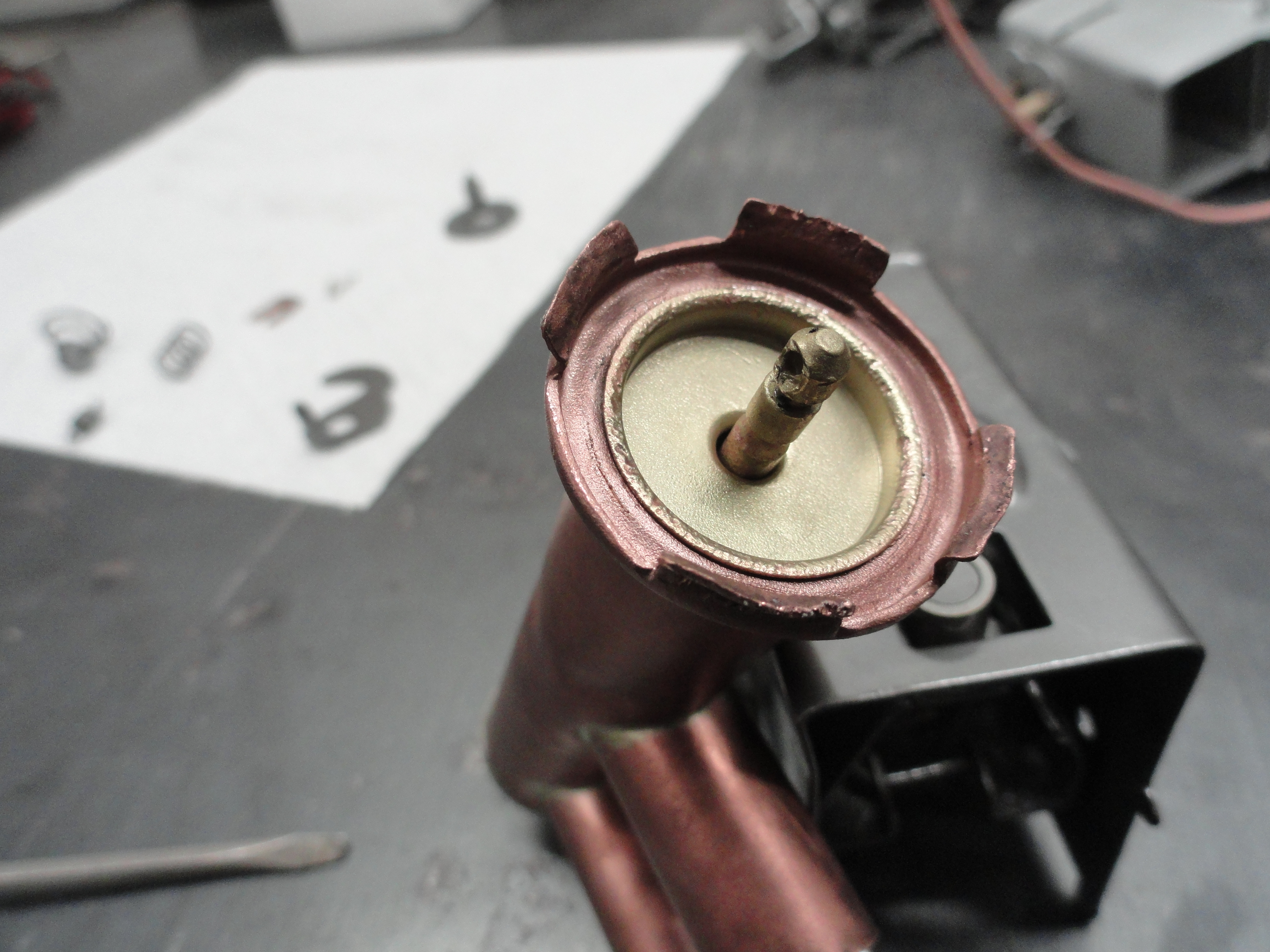
With the shaft clamped in place, install the large copper cap if you have one, and then install the rubber seal as shown. I put a little lithium grease inside the rubber hole to slide it in easier. Once you have it down below where the groove is for the crimp-on slotted clip, install the small copper bell over the seal, then crimp on the slotted clip. You can remove the Hemostats now. You want to make sure the tabs on the copper assembly are nicely bent. What I mean by this is, no stress is placed on the base of the tabs, and you can easily slide the copper tube assembly in place. Look at the pictures for the orientation. Be sure to get the tube inlets pointed in the proper direction. Once you have it placed by hand and it seats completely all the way around, insert a thin screwdriver into the slot you are working on as you bend the tabs back by hitting them gently with a small brass hammer. This keeps the base from distorting and causing a leak. Don't jamb the screwdriver into the rubber seal you just replaced! It is merely there to keep the tabs from distorting the underside of the copper assembly. Be slow and deliberate and finesse those tabs into place. Once you are 90% there, you can be just a tad more aggressive with the hammer to set them.
Now is a good time to test your new seal assembly for leaks. Since the radiator and cooling system is only pressured to 4-7psi, it is not hard to go over to the nearest water faucet and run water through the two outlets with a little pressure. No water should seep through the seal. If you did the above right, you are good to go on to the next step! Which is installing the Copper tube and Bellows. Orientation is important, so look closely at the pictures. To bend the tabs on this assembly, I used 2 Hemostats and clamped the assembly to the frame and then a needle nose pliers right at the tab you are bending. The Hemostats hold everything straight while the needle nose pliers does the work. If the needle nose pliers do not give you the reach due to the contour, use the edge of a screwdriver tip or something to give the pliers the depth needed to crimp the tabs. Be careful in working with this assembly! It is easy to damage the copper bellows.

Now for the tricky part. Face the slotted clip as shown and insert the spring in between the slots. Bend the slots just a bit to hold the spring in place. If the spring were to fall out during the next part of this, don't sweat it, you can install it last if you want. To assemble the faceplate to the rest of the assembly, two things have to happen at the same time... the bellows plunger needs to sit perfectly centered on the bellows while on the front part of the assembly, the two slots have to be aligned to go into its holder as shown (next frame left). To keep the bellows plunger and spring from moving, you can always tape it into place. Tape it where you can retrieve all of the tape when done. Some of you do not have this type of plunger. You have one that doesn't use a spring. Install that in the correct orientation and no taping is necessary! That one requires that you keep the tabs on it aligned with the main body so everything fits together properly.

I found the best way to do this step is with a small 12" adjustable squeeze type woodworking clamp. The idea is to clamp the faceplate to the main assembly and hold it there long enough to bend the tabs down. You can't do it without clamping force and it's not a good idea to force things into place. The bellows is very fragile and the plunger with the spring in the center needs to be dead on center of the bellows before clamping. Take the time to center it, then put the assembly together as close to where the tabs will go into the slots as possible, then squeeze the clamp into place. If all goes according to plan, you have a clamped tight assembly and all you need to do is carefully, slowly bend the tabs down on each corner. Check the placement of the plunger to make sure it didn't move. Once you have it assembled, be sure to put the spring in place. I used a needle nose pliers for that. If everything aligned well, you are almost home!
Finish up by putting the adjuster assembly back on in the correct orientation which you marked earlier, then install the clip. The picture on the right is to show how the "warmer" shaft is placed on the end of the assembly. The Clear Coat will keep it from rusting and the assembly is ready for action. To test the system, you can get a can of Freeze Spray from your favorite vendor. Do a search for Freeze Spray on the Internet and you will have no problems purchasing it. To check the assembly, spray the freeze spray over the bellows while looking at the rubber seal assembly. If it works as intended, the plunger will go down magically all by itself! Do not freeze it too much. Just hit it with a few short shots. This mission is complete! If you have questions or suggestions on how to improve this document, please email deve@speedprint.com.