


Deve's Technical Network
1947-1955 1st Chevy Trucks
216/235/261 Engine Solutions & More

It's almost funny the resistance to this project that I had to endure in researching this subject. Almost. Okay, to be perfectly honest, it wasn't funny at all. It was very revealing about the state of our citizenry, and very depressing, but I pushed on anyway. Imagine people so afraid of tarnishing their ego that they would go out of their way to explain in detail, through several threads on several forums, the stupidity of doing this research. Remember, they didn't have to post anything at all, rather, let the answers be judged on their own merits. No, these people feel adamantly that anyone who should research putting a Critical Information System in their Vintage vehicle is contributing to the downfall of America as they know it. I hope to NEVER know America the same way they do. Striving to be the lowest common denominator is something that just saddens me. It wastes everyones time who sincerely wants to know more and at the same time really diminishes the entire interaction. If you are one of those naysayer types, join the club, at some point in time we all are, but let others learn without interference from the peanut gallery.
This System monitors your Oil Pressure, Charging System, Engine Water Temperature, Fuel Volume and other systems you choose to monitor and provides either an Audible warning, or a warning light depending on how you configure it. This of course isn't anything new and if you drive a modern vehicle, you don't give a second thought to the systems that notify you of a malfunction. But if you have a vintage vehicle, you also know they do not come equipped with such a system. Some of us value our vintage ride more than our modern drivers, so why not put a warning system in your vintage ride?
Let's examine why this would be a good thing to have. Scenario: You are driving down the road with a friend in your precious vintage ride, talking and just enjoying the day. You are a very good driver and you have a system for scanning the gauges that is guaranteed to prevent damage caused by malfunctioning systems. All of the sudden one of the flex lines breaks in your Oil system. Since oil is pumping out all over the highway at the rate of about 15 seconds per quart, you have about 60-90 seconds to shut down the vehicle's engine and coast to a stop before doing major internal engine damage. Now I ask you.. wouldn't you appreciate an audible warning on such a critical system that sounds off the second oil pressure is lost? Isn't one of the reasons you appreciate your vintage vehicle is because it takes you back to a slower, simpler time when things were less anxiety prone? Yet, without this system, you BETTER be scanning your gauges at regular intervals! Well, I prefer to enjoy the drive and let the vehicle tell me what it needs.
As with all things on DevesTechnet.com, this Critical Information System is documented so that you can make it yourself without any money changing hands! This article explains in painstaking detail exactly how to do this yourself. If you cannot do this yourself, we will provide you a means to purchase one from the site. As with everything else, all proceeds go to keep our vintage resources online and up to date.
We need to take this one system at a time, so let's focus on the basic requirements. First we need 12 volts Switched Power. This will be provided using the Ignition Switch. Ignition ON will be our power source. Next, we need the system to know if the engine is running or not. Of course there is no Oil Pressure when the engine is not running right? Each of these things that are no-brainer's to us are important to teach our circuit so we have a useful system. Next we will need Sensors to tell us when a certain system is malfunctioning. Now let's focus on what we want to monitor and what will be required.
We will start with a list of requirements that your vehicle must have in order for this system to work. These same requirements were necessary in the very beginning
of the automated vehicle warning systems. We realize we are talking about vintage vehicles, so anyone having information on workarounds for any of these, please let
us know.
Vehicle Requirements:
Now, let's break down the individual systems and the requirements for each one.
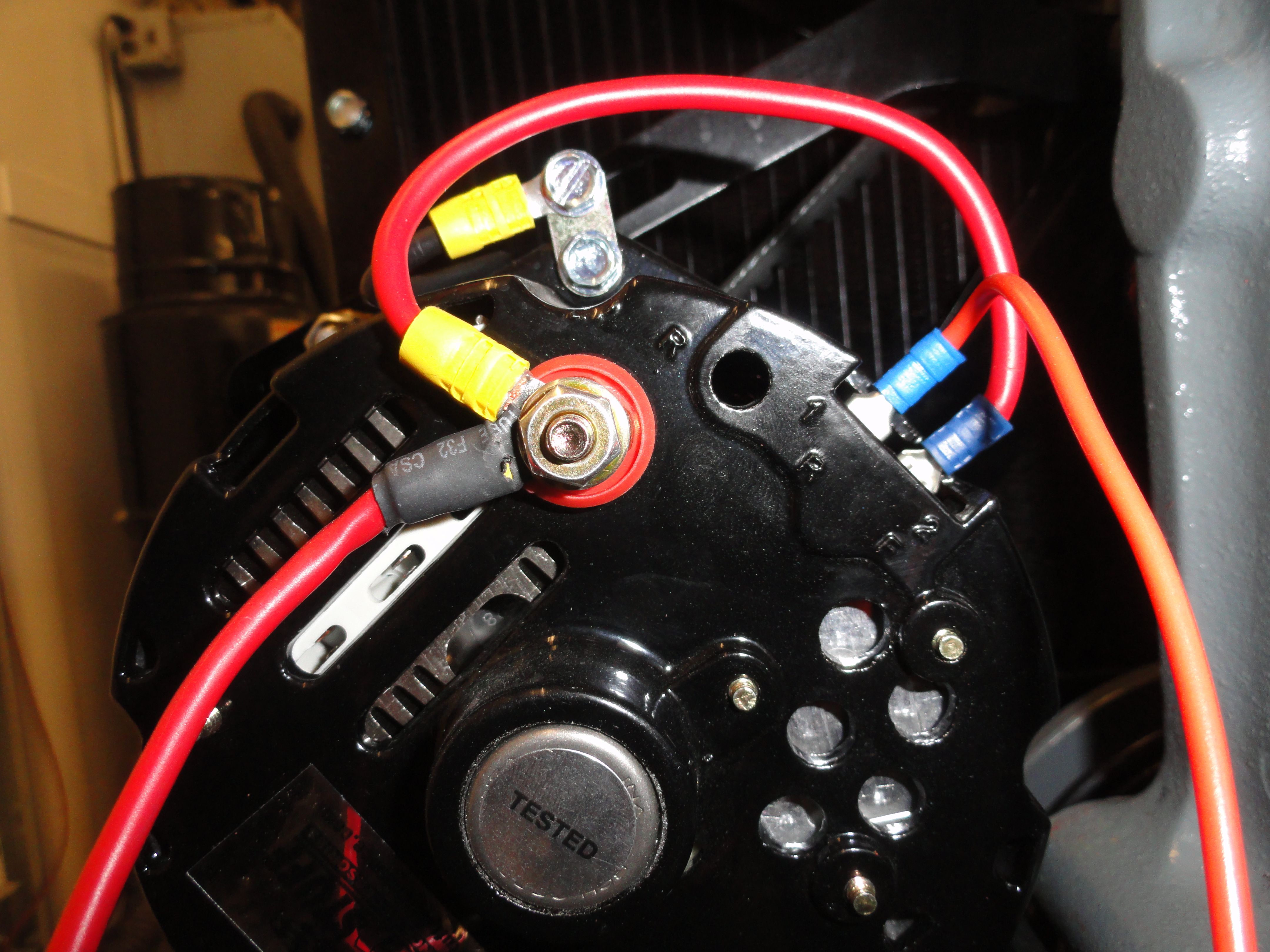
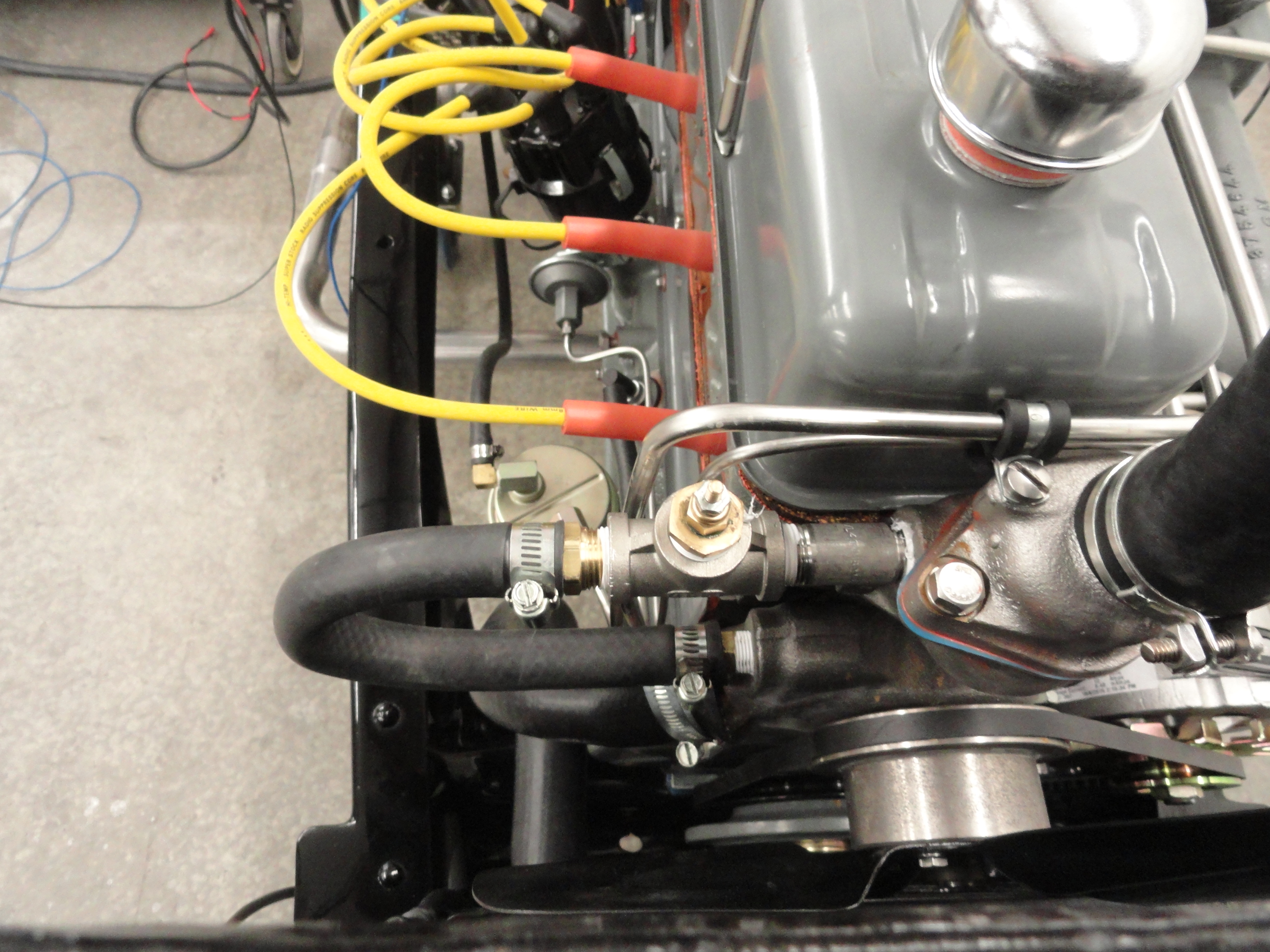
The wire going out of the picture to the right is the Warning Circuit wire. It is the small terminal closest to the main terminal on any 10SI or 12SI Alternator and is labeled '1R'. When you purchase a new Alternator, the two terminals are covered with a rubber plug. Lifting that plug reveals two standard 1/4" terminals. The one labeled '2F' is the Field Wire and is furthest away from the Main screw terminal. This instruction assumes there is no terminal connector on those two terminals. If you would like to have a plug (connector) with the two wires coming out of it, the NAPA part number is VRC148 or Airtex/Wells part number 1P1019. Normally, 1R goes to the warning light in your vehicle, and 2F is jumpered right down to the main screw terminal on the Alternator as shown. This gives the Alternator is excitation voltage.
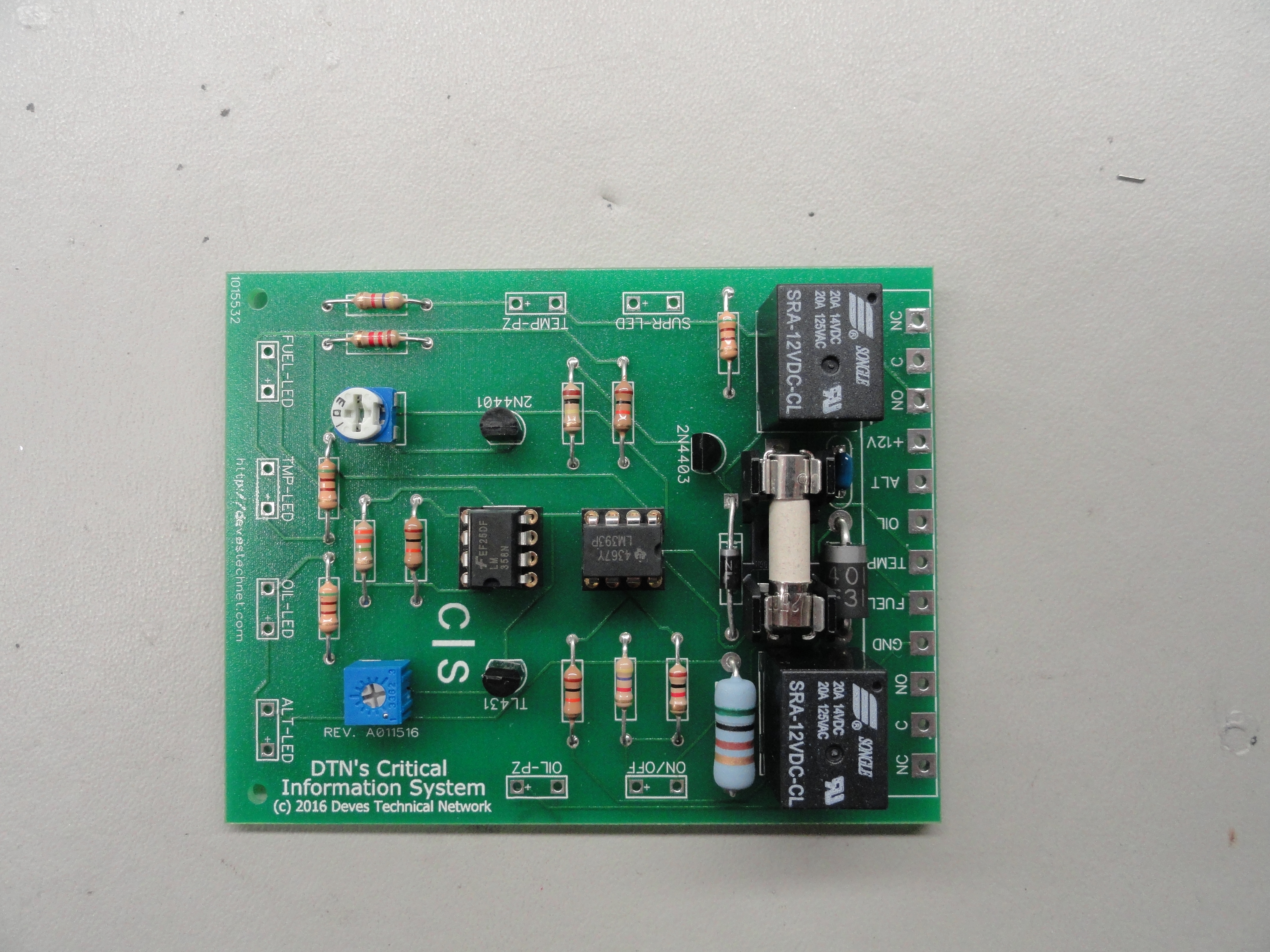
Let's examine the schematic diagram of the entire circuit. The dotted lines are the demarcation for each individual 'service' we are incorporating in the basic design. Everything fits nicely on a 7cm by 9cm circuit board. For you lost Americans out there who still use the inferior Standard System of Measurement, the board dimensions are 2.75 x 3.50 inches. (I am kidding.. I am from Kansas!) The reason we use the metric system is because the enclosure we are using also uses it, and the enclosure has a nice track to slide the board in to as long as we use 7cm. All Relays, Discrete and Passive components are on the printed circuit board with terminals to attach all of the outside components, such as Thermistor, Piezo Buzzers, Switches, LED's etc.
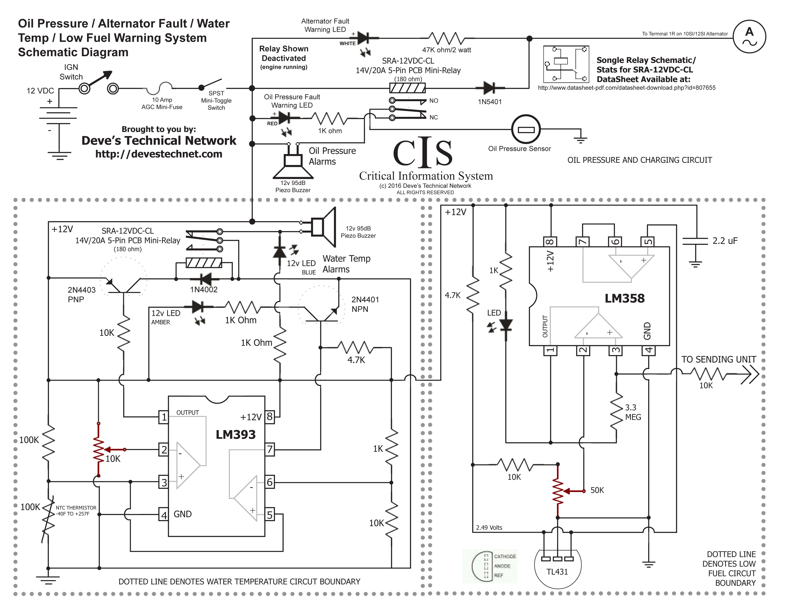
(Partial Circuit Design Courtesy of our Friends at All About Circuits. Special Thanks to Dr. Mike Mladejovsky, Phd EE for his design of the Low Fuel Circuit and MarcF for his design of the Supervisor Circuit. This is how truly great things happen. Cooperation and Collaboration!
Explanation: The Oil Pressure Relay is activated when engaging the ignition switch due to the difference in potential between the battery and the warning circuit in the Alternator. The Alternator Fault Light is also bright before the Engine is started. The Low Oil Pressure Warning Audio is suppressed because the relay takes the contact off the Normally Closed (NC) and puts it on the unused Normally Open (NO) contact removing ground. On startup, the Relay saturates when the potential equalizes and the Relay shuts down as does the Alternator Fault Light. At the same time, Oil Pressure removes the Sensor's ground so the only time the Warning Audio is heard is if oil pressure is lower than 6 psi WITH the engine running.
Water over-temp warning is accomplished through a Relay Circuit that depends on a Thermistor heat sensor. This fully adjustable sensor (-40F to 257F) can be set anywhere you choose but best around 220 degrees. Once it reaches its set temperature, the relay applies ground to the buzzer and LED. Once the temperature goes below its set temp, ground is removed again and the buzzer/LED go off. We have also incorporated a fault system (supervisor circuit) that monitors the wiring to ensure everything is connected and working properly. Without the supervisor circuit, you could have a broken thermistor wire and not know it.
Low Fuel warning is accomplished by using the output of the existing Fuel Sending Unit. The system monitors the very low voltage that is present and when it reaches the voltage that equals your desired warning level, the LED illuminates. This is adjustable from Empty (0 volts) to Half Full (approx 1.6 Volts) using a 6 volt fuel gauge and Empty (0 volts) to completely Full using a 12 volt fuel gauge. The gauge comes into play because it delivers the voltage that activates the sending unit. Keep in mind, however, our box is merely monitoring the sending unit to gauge signal and reporting back when conditions are met.
This circuit has been tested thoroughly and works as advertised. The idea is to make this circuit as compact as possible while delivering everything expected. This philosophy leads to much less concern about circuit failure. The fewer parts the better! Speaking of parts here is the Live Master Parts List. Each part and each vendor is chosen for quality and reliability. This circuit is no cheap knockoff, rather, it is THE original American Made Critical Information System!
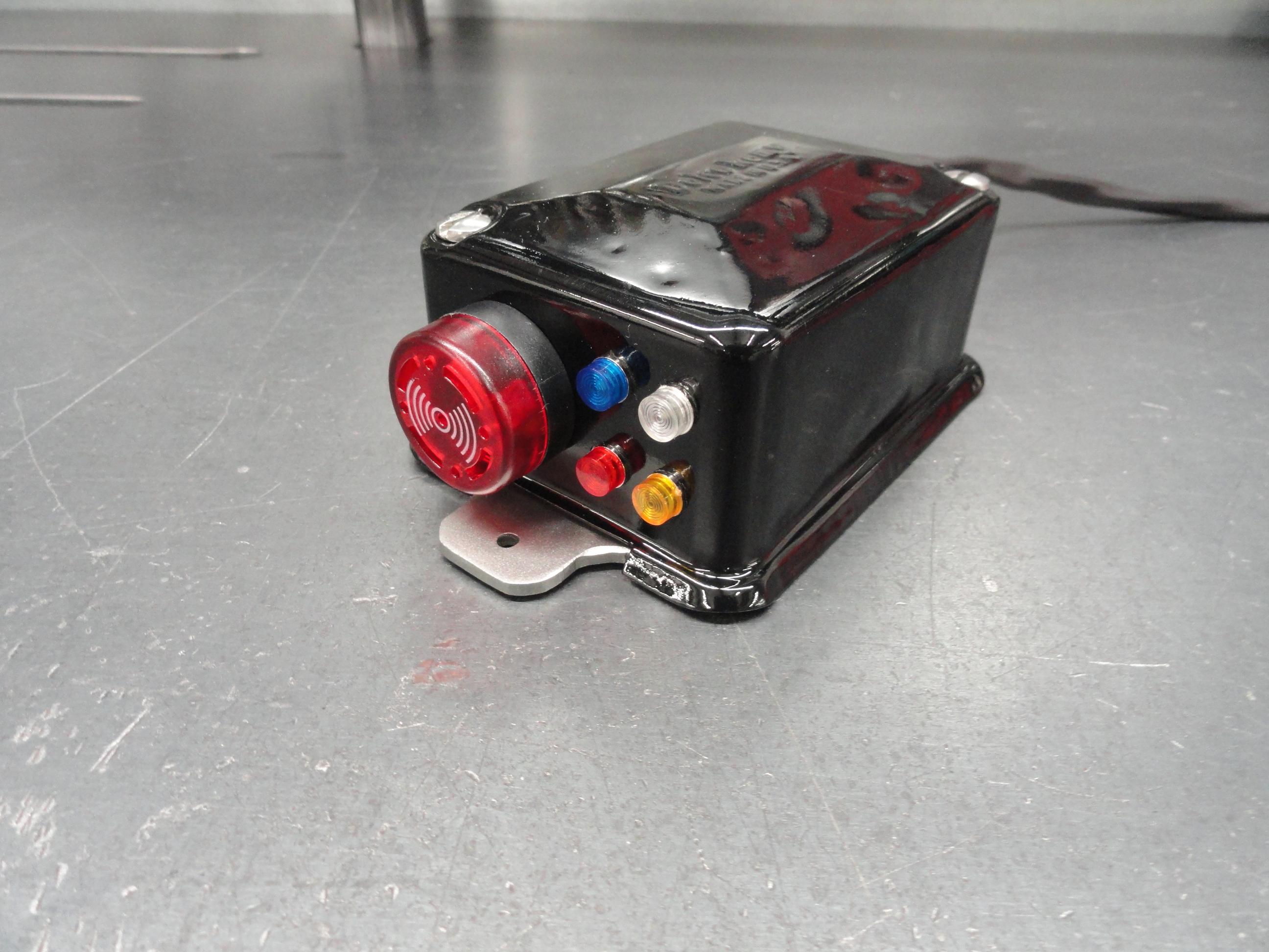
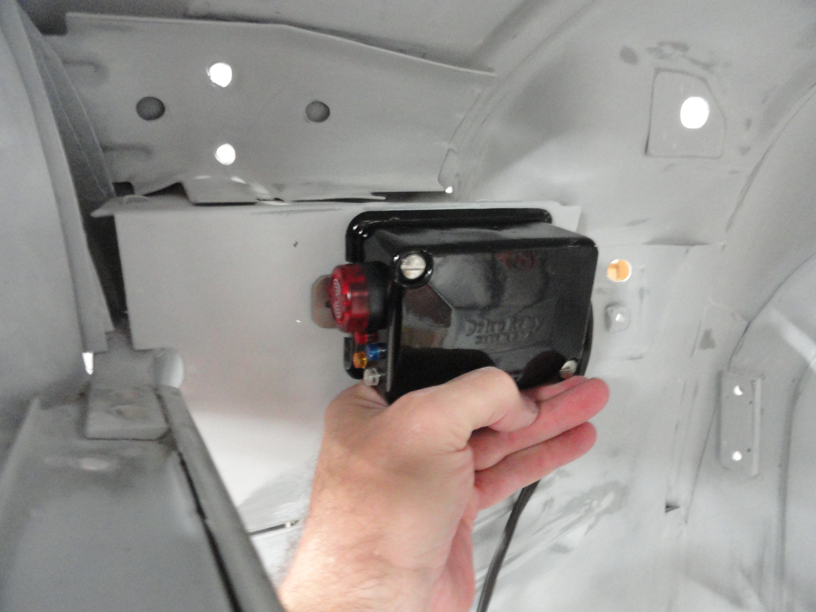
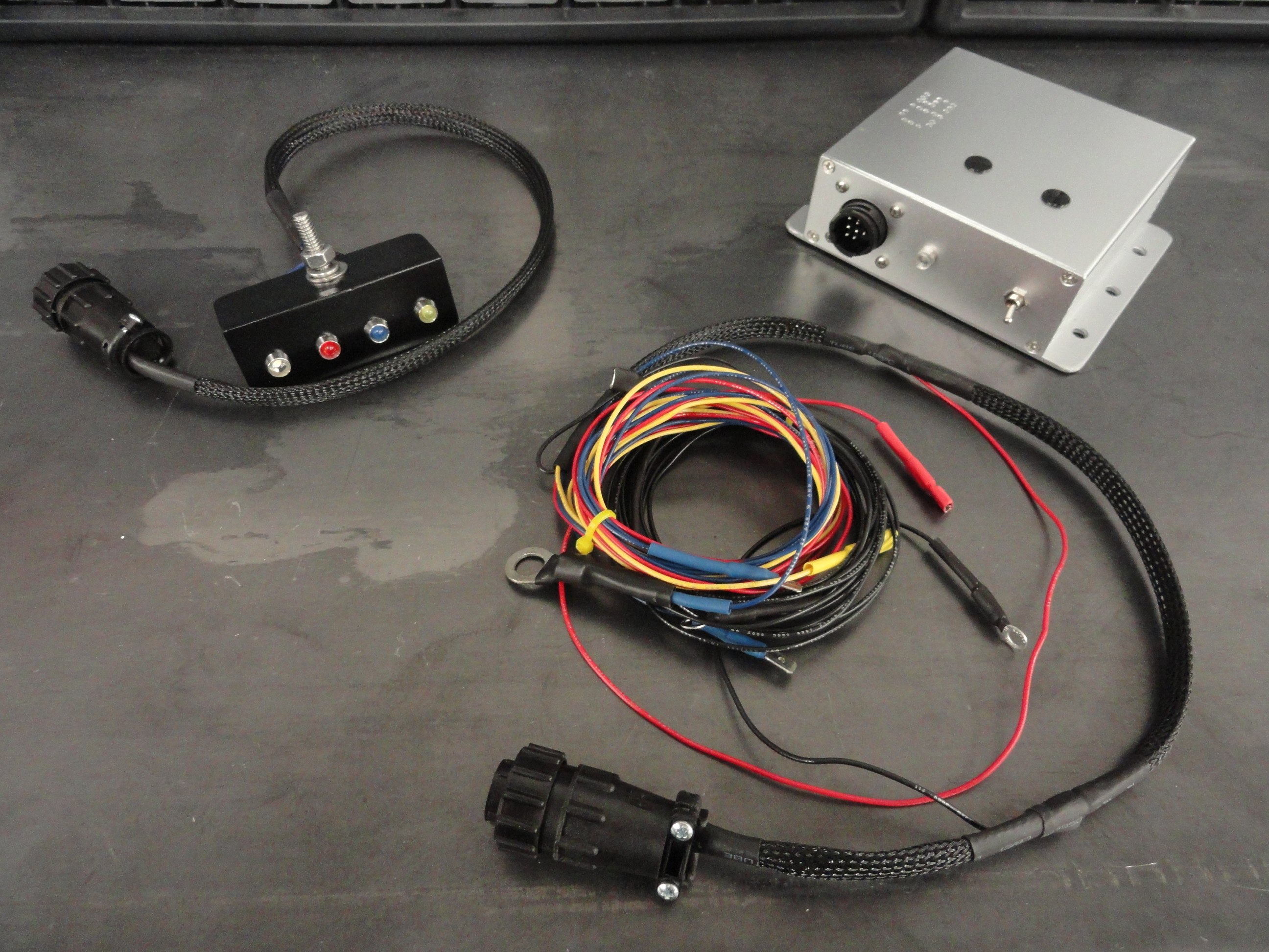
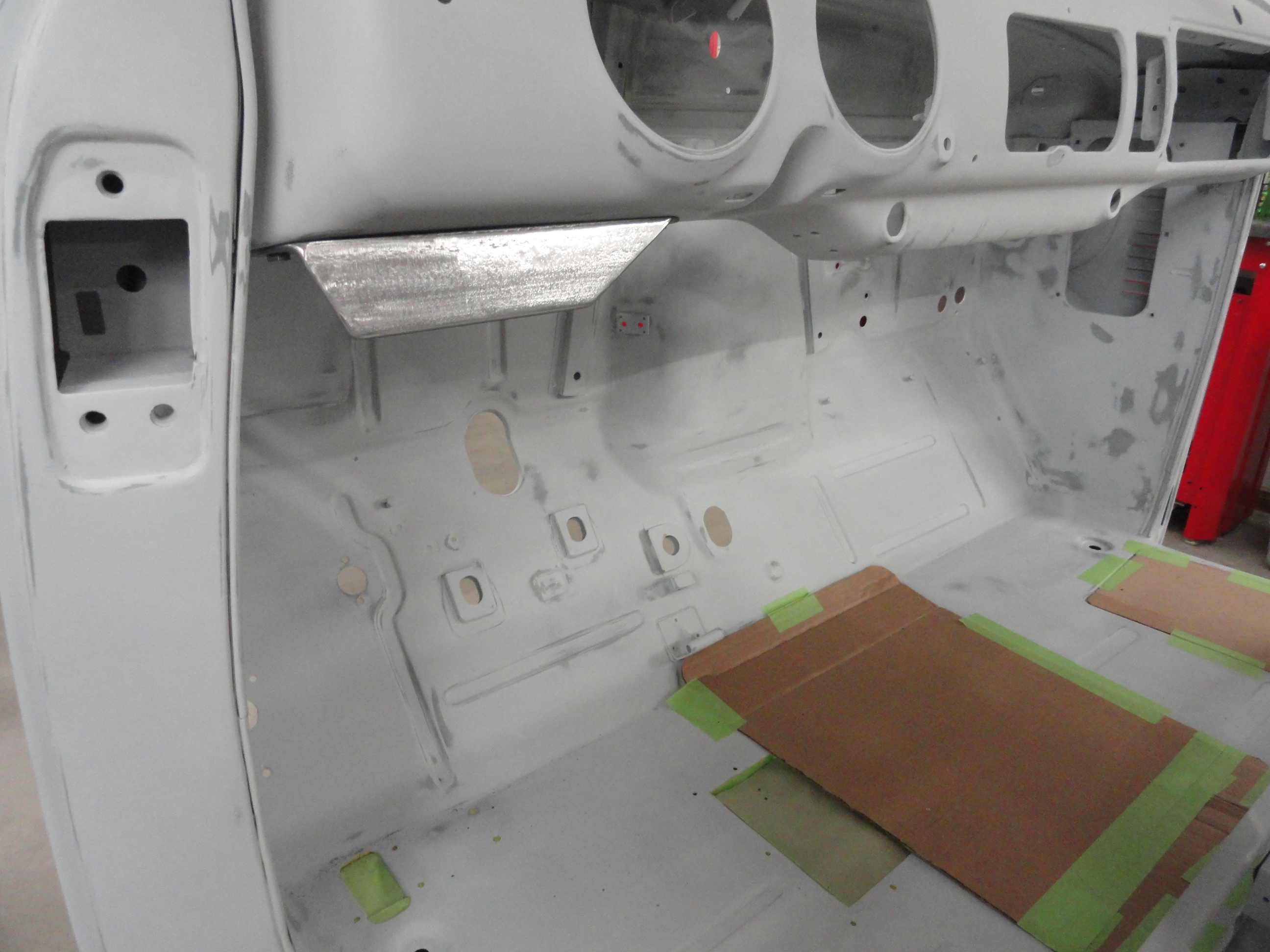
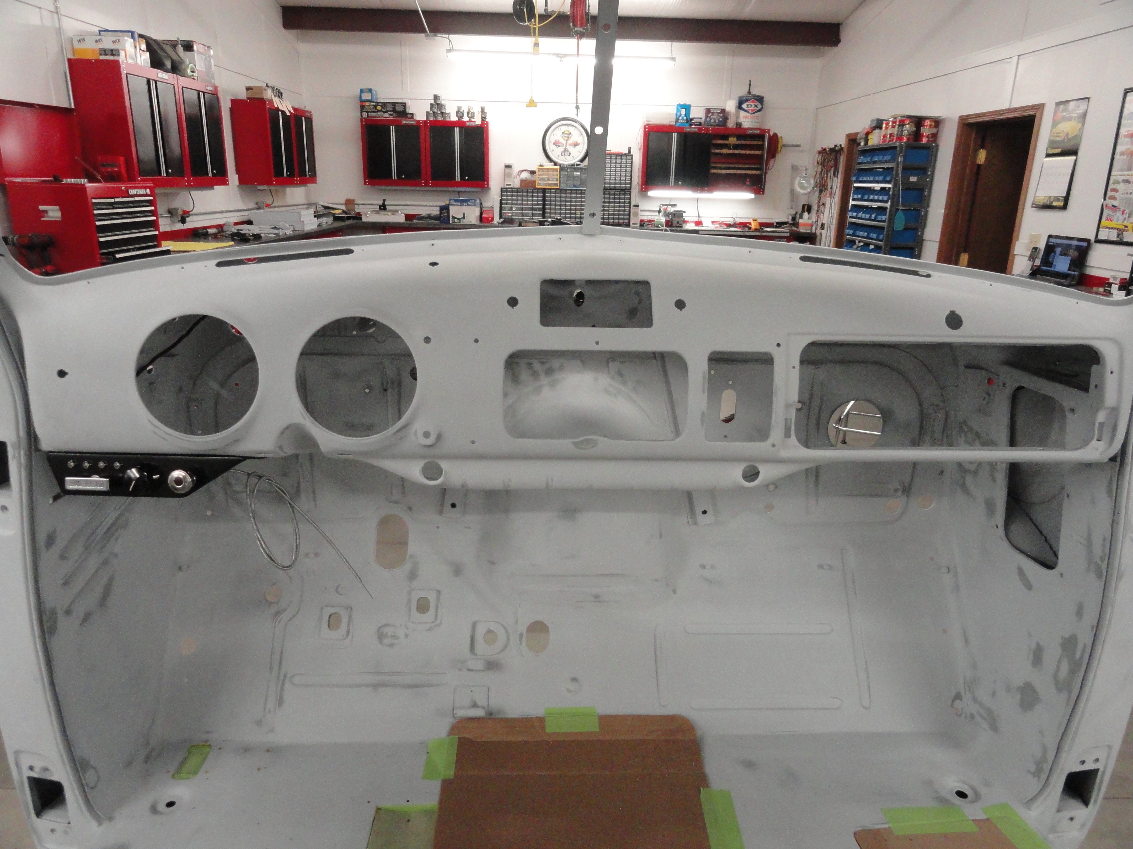
This is just a test design. My thoughts are.. WHAT ARE YOUR THOUGHTS?? So, on one hand I do not want the lights to show up on the dash because I want everything to look stock. For this reason, I chose to mount the box just at the top of the drivers side kick panel. The driver will not see the lights without getting out of the vehicle and looking under the dash. That is okay with some since the most critical of the systems being monitored (oil pressure and water temp) has an audio alarm. The nice thing about this system is it is a double check for the gauge system and uses no part of the gauge system making it a true redundant backup system. If I see the gauges do not read as expected, I can look under the dash for confirmation. If you are not as 'stock conscious', I also made it so the lights can be taken out of their mounting holes and I used spade terminals so you can just make the wires longer and put them anywhere you choose. I would LOVE to hear your thoughts on this.


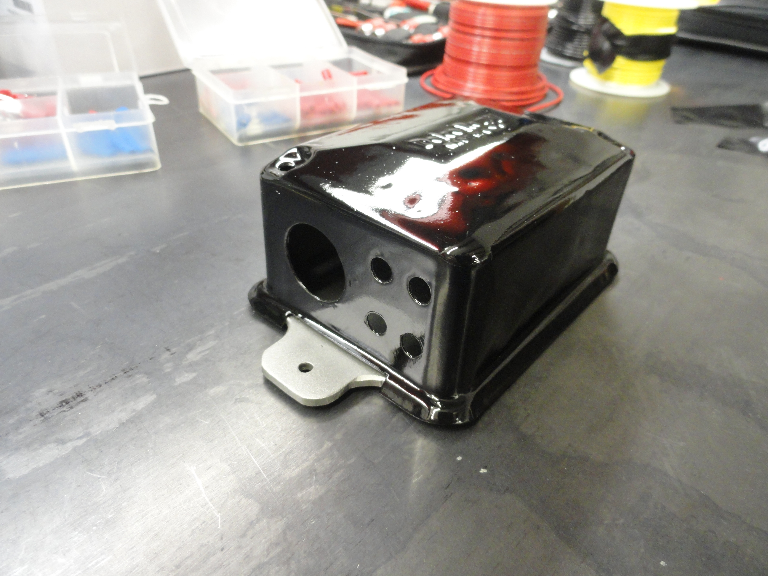
I started with the box and began by drilling one 7/8" hole for the Buzzer/Light I chose for Oil Pressure. This Buzzer/Light Combo is not in the parts list but available on Ebay from time to time. I then made 4 holes for the small LED Lights so that I have 4 more choices of alarm lights. I used a Letter E drill bit because that was the perfect diameter for the LED's I purchased. You can use incandescent gauge lights, or whatever floats your boat. I finished the drilling of the cover by drilling a 3/8" hole on the other side for a 3/8" grommet to thread the wires through for Power, Sensors, and Alternator.
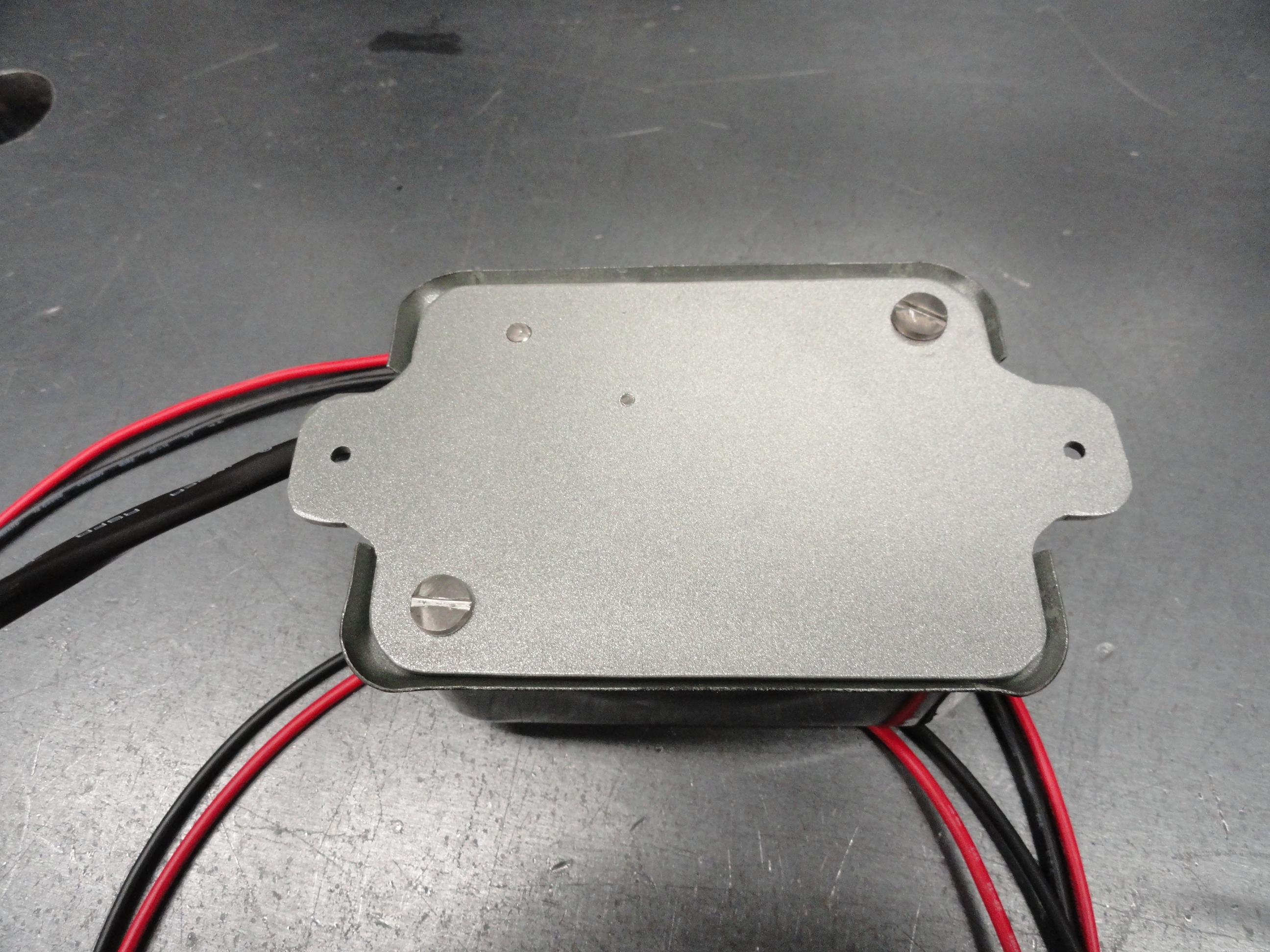
Next I addressed the base of the box. I wanted it to fit inside the lip of the cover but have two tabs on it for screwing it down to the Cab interior. To do this I had to cut the Cover as shown around the bottom tabs. I did that with a Dremel tool with a cutoff wheel attached. The base of the box is made out of 3/16" plate steel and the dimensions before cutting was 3 inches by 5 inches. The box is 3 by 4 so that left 1/2" on each side for the tabs. I use a Dewalt Porta-Band bandsaw with Swag Offroad Table to cut these out. I then layed out the parts so that everything fits. This box is really the perfect size. The relay and a fuse holder are the only things screwed down to the case. I used 2 inch standoffs (10-32 threads) for screwing down the cover, 10-32 screw for holding down the relay, and 4-40 screw for holding down the fuse holder. #10-32 screws use a #21 drill bit for tapping, #4-40 use a #43 drill bit for tapping.
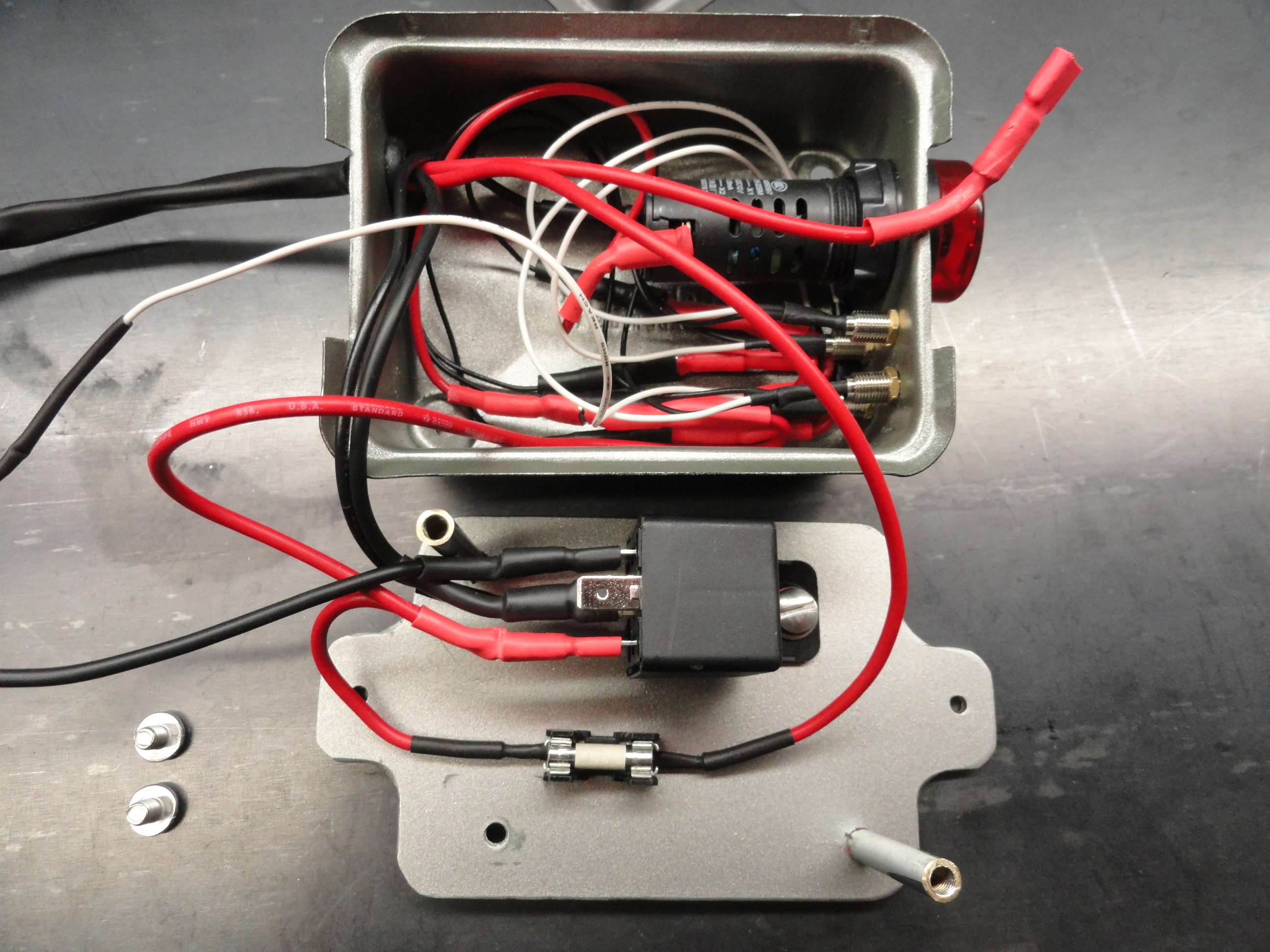
It takes a little doing to get all of the parts inside the box. Since this is a scalable system, it would be better to have a larger box. Especially if you feel an audible alarm would be good for other systems. Of course you can use the same buzzer for multiple systems, but what if you want different sounds to differentiate? That's part of the fun! Deciding how you want to customize the system.
The final Black Box to hold our Critical Information System was chosen for its perfect size and compatibility with our circuit board. Since electronic components are a worldwide issue, we go with the Metric System for the circuit board and the on-board components, and Inches for the outside of the Black Box. This box has a special groove that accepts 7cm circuit boards and ours is 7cm by 9cm (2-3/4" x 3.5" inches). Interestingly, the dimensions of the Black Box are 3.5 inches wide, by 4.25 inches deep by 1.5 inches high. So it doesn't get any better than that!
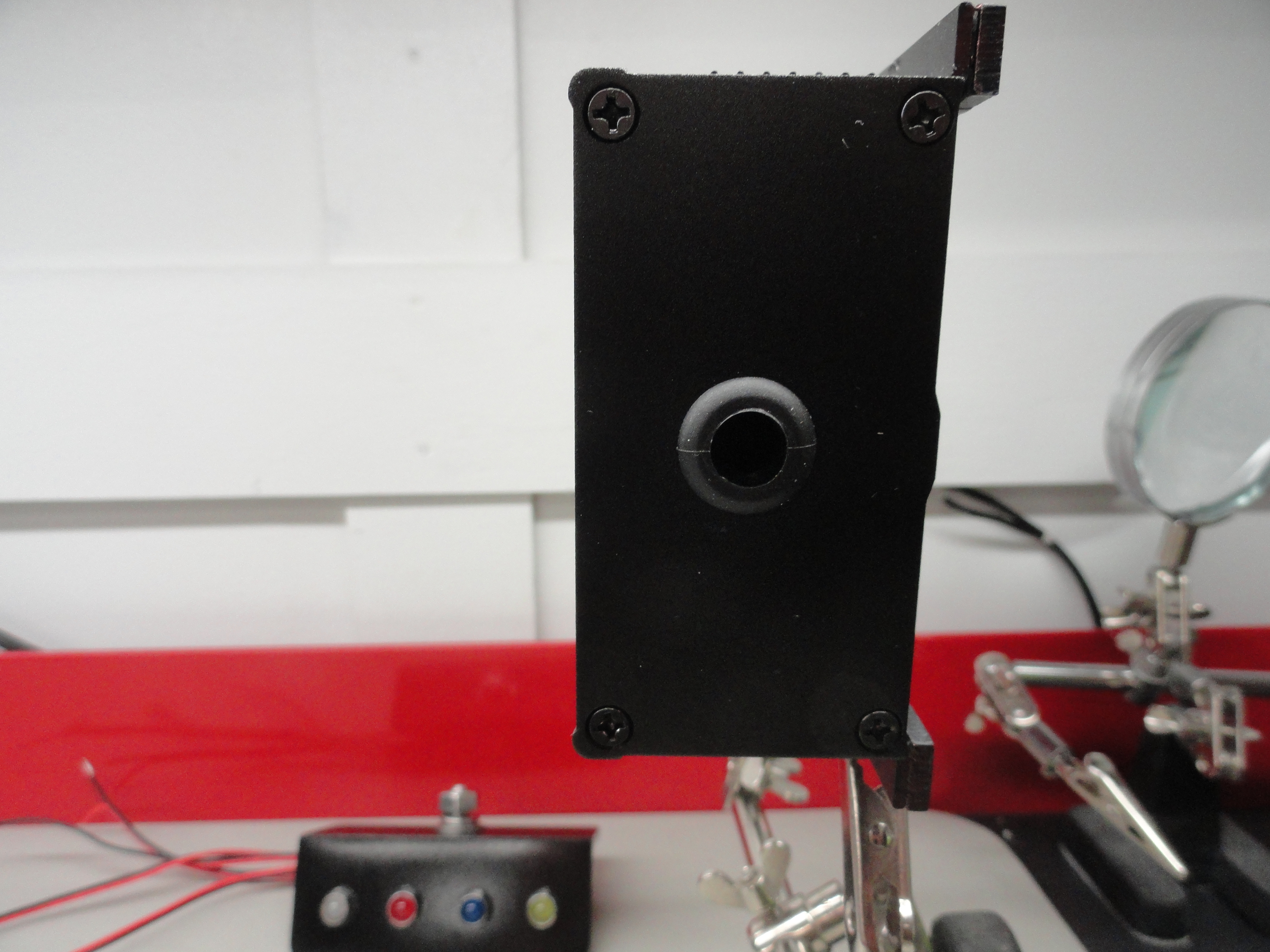
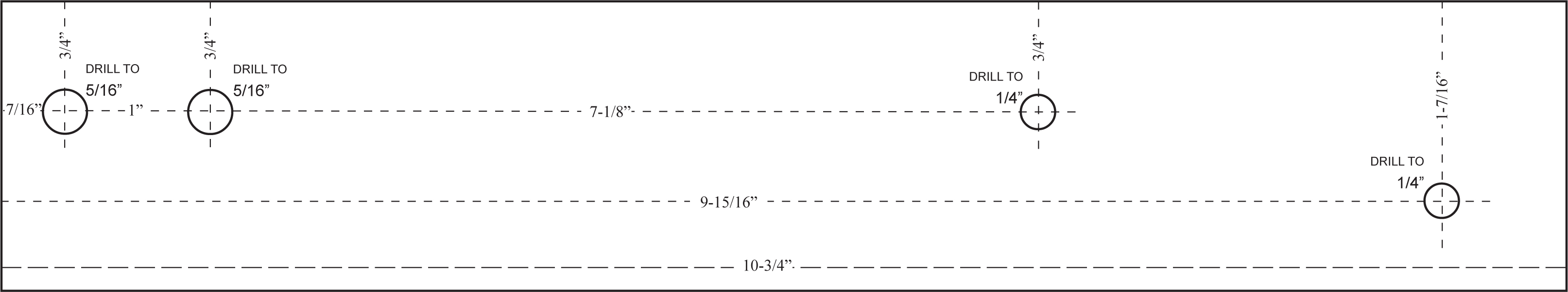
We have several things to do before we start working on the inside. These activities include Drilling and Tapping in the appropriate places for our project. Let us start with the end pieces. The enclosure is fully enclosed except for two end pieces that are 3 inches by 1.5 inches. The Box comes with the screws for fastening them down, so all we need to do is customize each end for our purposes as shown below:
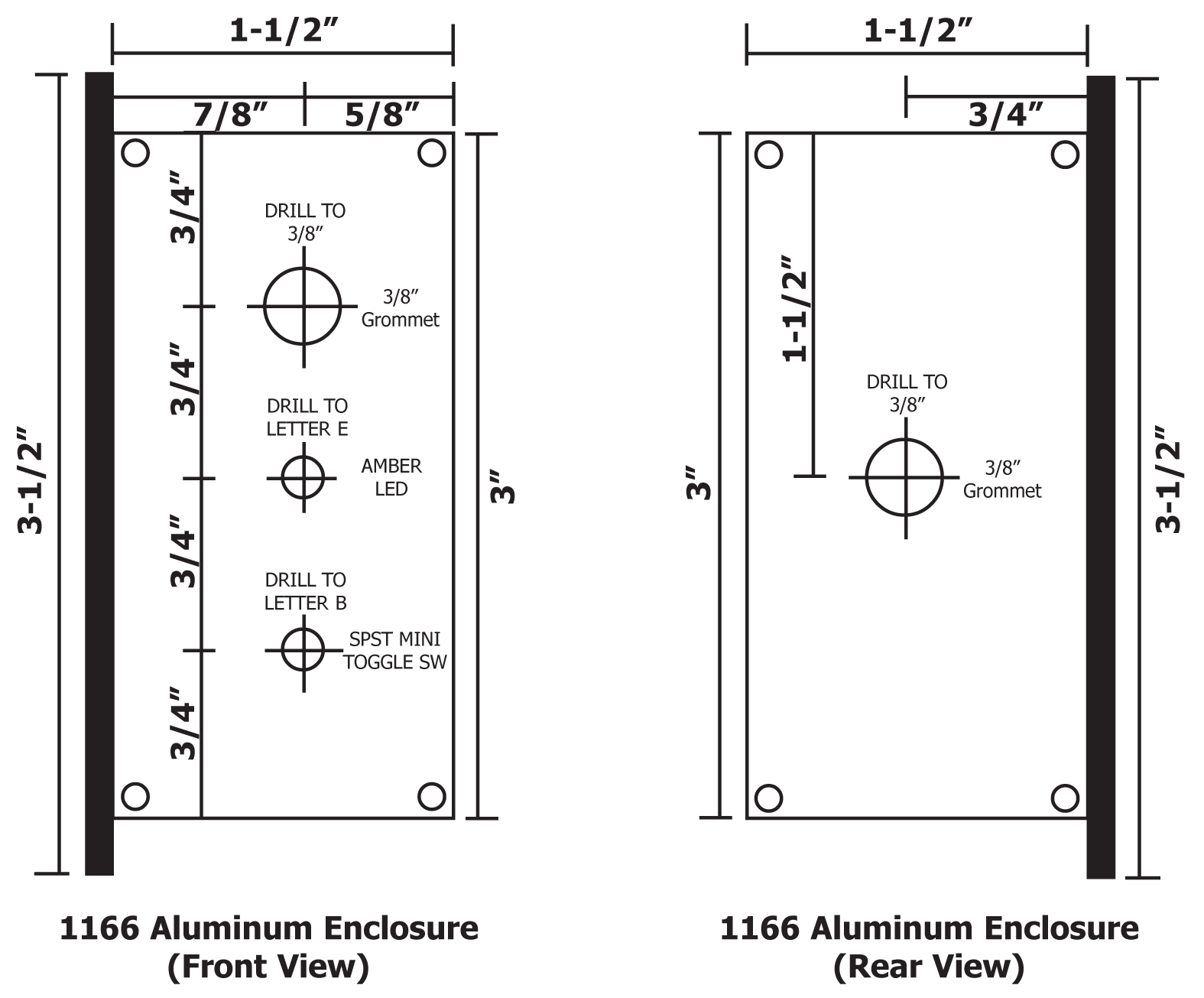
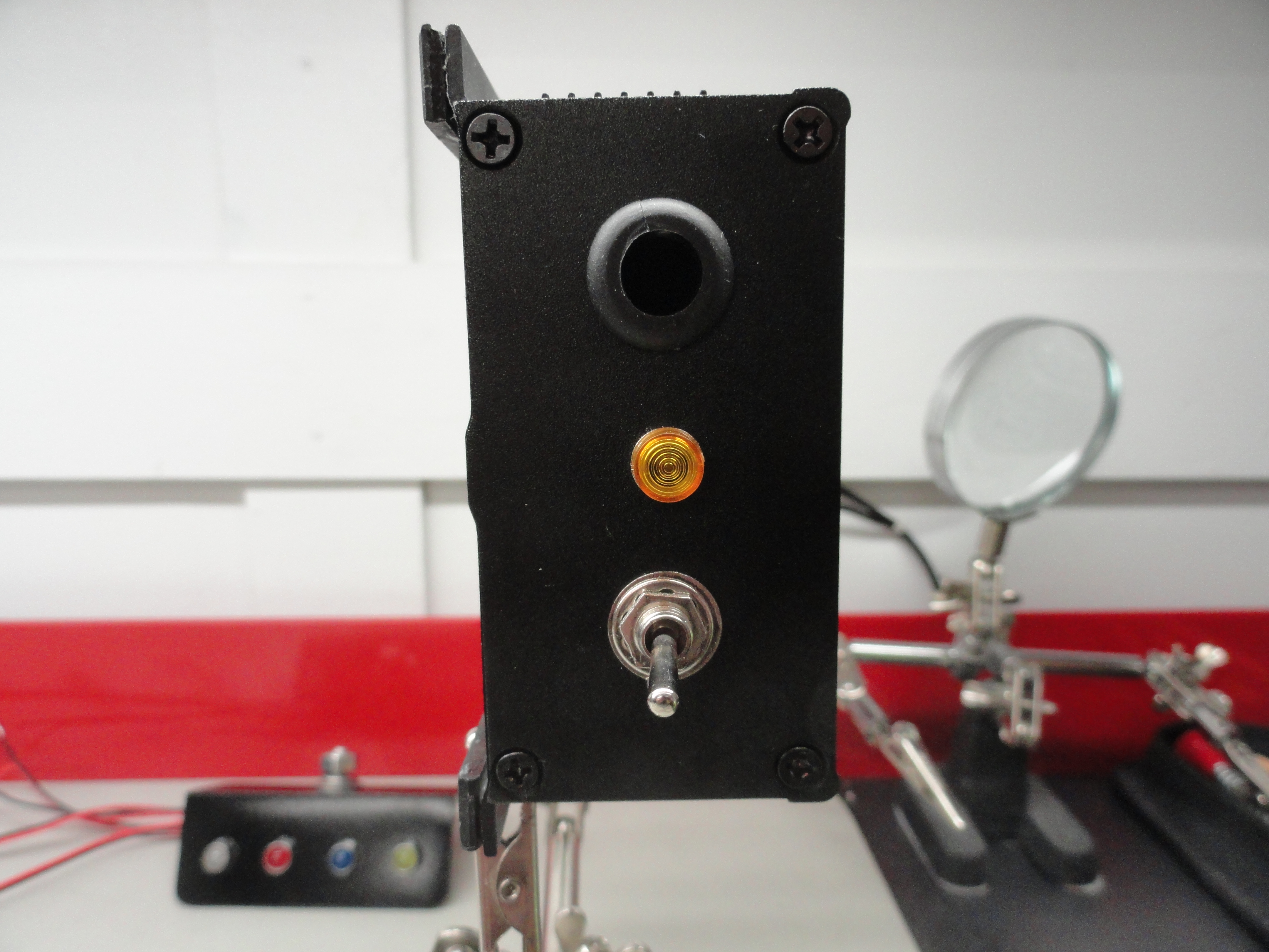
The 3.5 inch side of each drawing is the Mounting Side of the box. On the front view, the Grommet is at the top because that is where the LED wiring comes out closest to the dash. Next is the Amber LED that lights when a wire to the Temperature Sensor Thermistor is broken. Lastly, the ON/OFF switch for the entire CIS system. It is lowest on the box to make it easier to get to. This box is designed to be mounted high on the driver's kick panel.
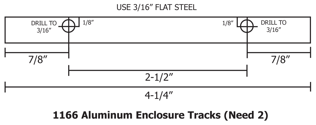
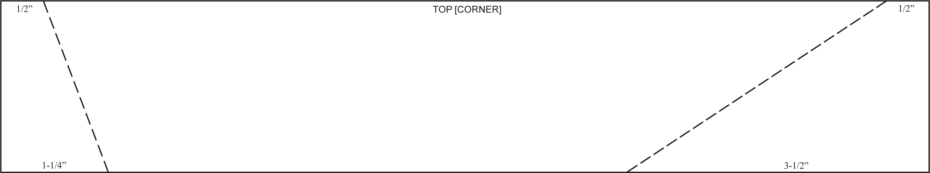
Another anomaly we need to content with has to do with mounting the box to ANY flat surface. The bottom of the box needs to accommodate the ability to have flat head screws coming up from the bottom to secure such things as grounding wires, etc. To allow for the ability to mount it flatly, we need to raise the mounting edge about 3/16". This is relatively easy to do by making two flat narrow strips. These two strips are then Epoxied to the bottom of the box with JB Weld. Here is the design for that:
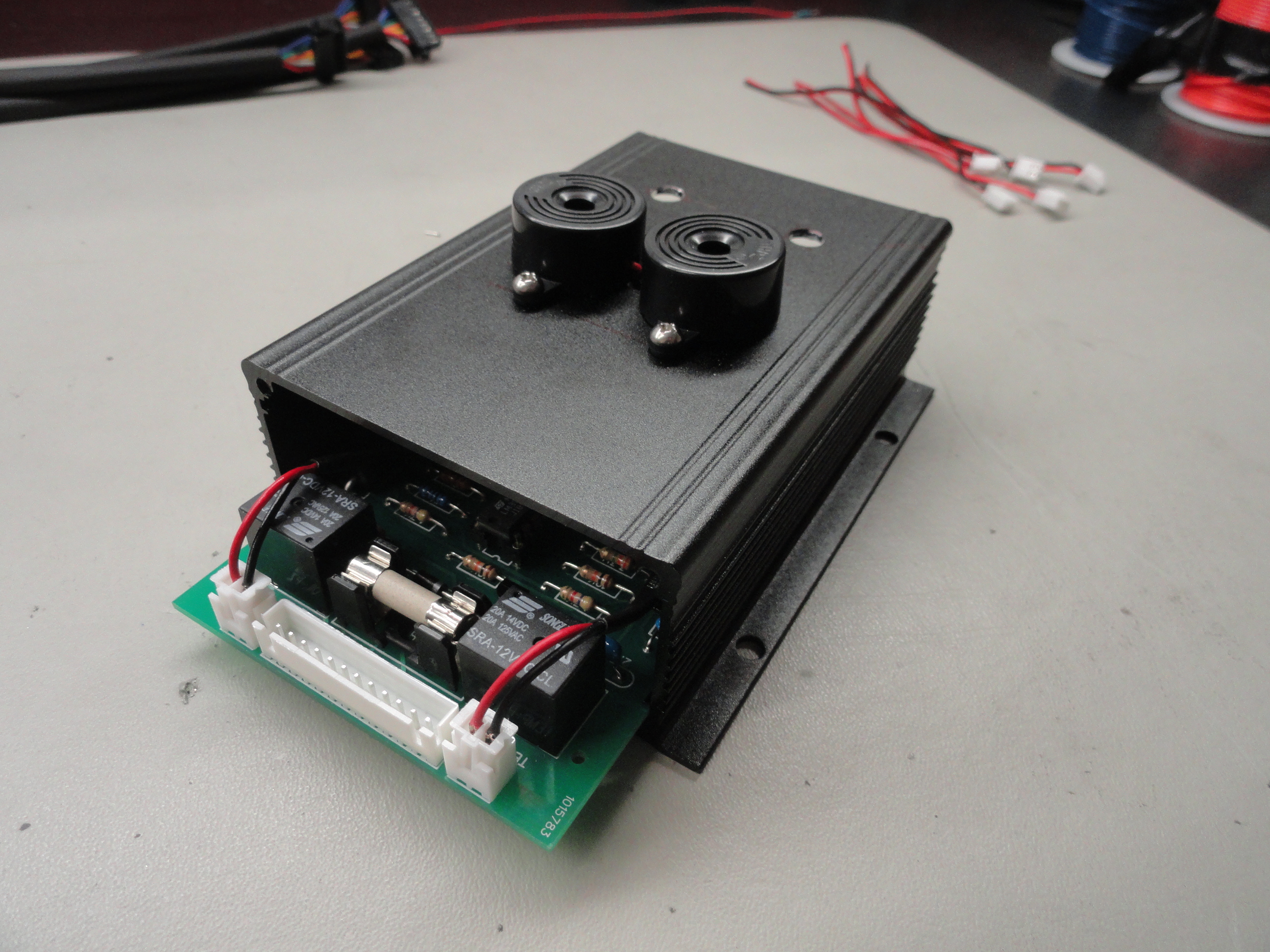
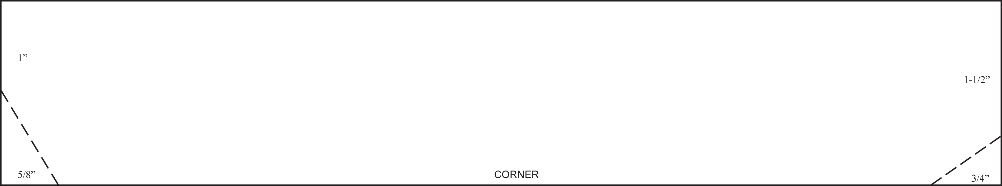
Now that the riser pads are mounted, all that is left is drilling holes for access to the two adjustment Potentiometers and drill and tap for the two audible Piezo Buzzers that are mounted on the top of the box. They are mounted on top so the Driver can hear them as much as possible. We will attach the chosen buzzers using 4-40 screws and to make it easier, we will tap the box so we do not have to wrestle with nuts on the inside. This means a #43 Drill Bit for that purpose. The holes for the Potentiometer are drilled to 3/16". That size was chosen merely for ease of getting a screwdriver down into the box for adjusting. Below is the drawing for the top view.
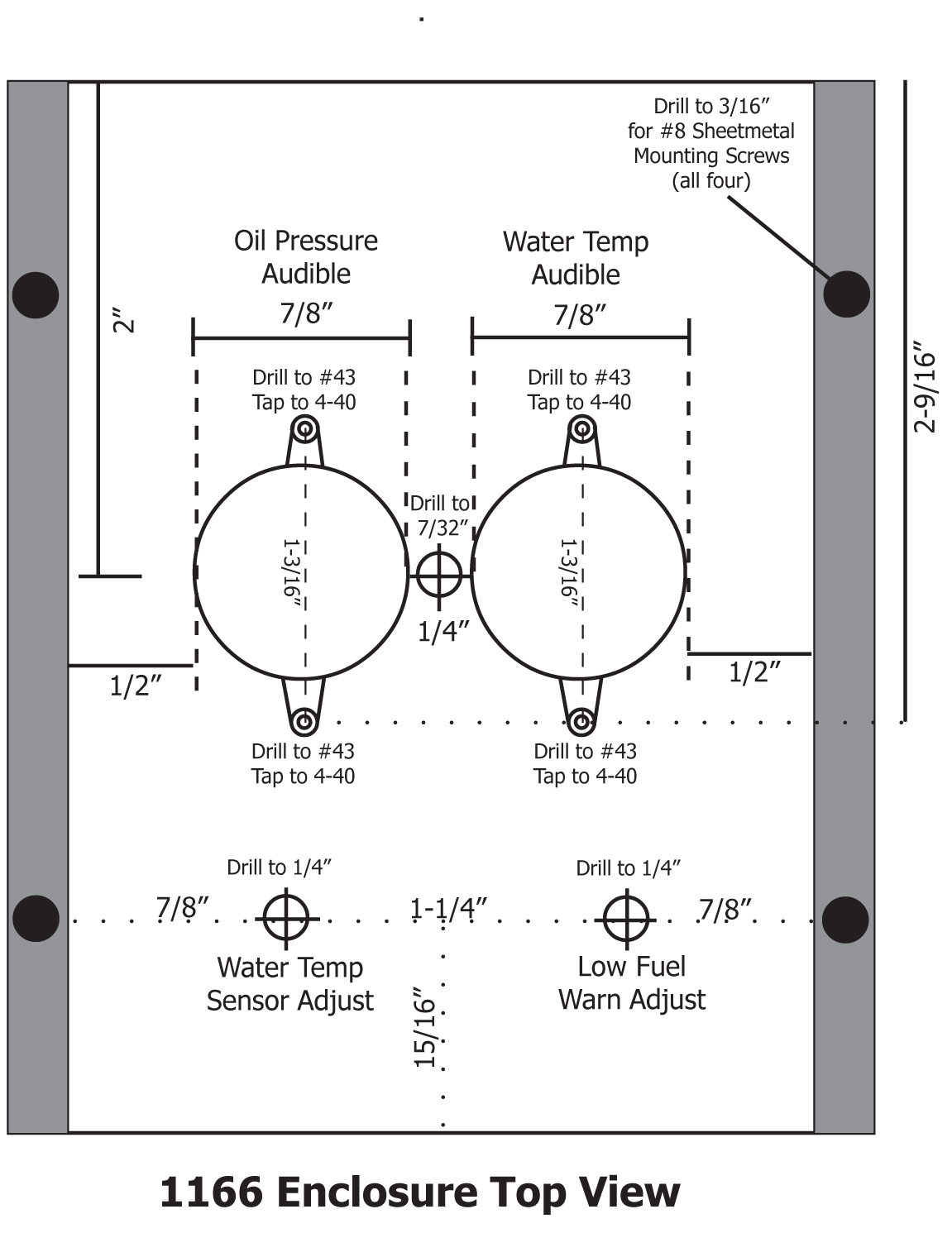
To install the Piezo Buzzers, they are screwed into the tapped 4-40 holes per the diagram. I found a #37 drill bit to clear out the holes in the Piezo buzzers made installation of the 4-40 screws a bit easier. The hole in between the buzzers is for the two pairs of wires to go back into the box. A 3/16" hole works pretty well for that. I use a small file to relieve the sharp edges so the wires are not damaged. Since there is lots of room front to back for the circuit board to slide around, I chose the placement to be pushed maximum forward so the suggested placement of the Potentiometer holes is with that in mind. The board floats in the slide but with the wires all soldered to the back of the board, it will naturally push against the front, so no need to fasten it down in any way.
Wiring is very straightforward and we made sure to mark each hole on the circuit board for placement of everything including the wires that go to various places. One place I did Deve-iate from the plan a bit was to make a ground lug on the side of the enclosure. The side that is the TOP when its installed in the Drivers side kick panel, in the middle between the two installation holes, I drilled an 11/64 hole to accommodate a #8-32 by 3/4" flat head screw that protrudes out of the enclosure and serves as the ground for the system. The GND wire goes to that lug on the inside and then on the outside, the lug is wired to another lug that is fastened down when you screw the unit to the Kick Panel.
Another issue that needed to be resolved is the Thermistor Lug. The drawings elsewhere in this article provide for a very nice Lug housing for anyone having a 1/4" screw available on their Engines Thermostat Housing. While this works for most people with a 216/236/261 era engine, we decided we wanted to make a solution that uses a beefier lug housing with the ability to install the Thermistor Sensor on any Waterpump, or Thermostat 3/8" Bolt. There are really a few ways we can go with this. There is the Aluminum Barrel Lugs and there is the Steel Standard Lugs. Either one can be used and they both transfer heat sufficiently for our purposes. The idea is to protect the fragile Thermistor from the elements. Our Thermistor Circuit is designed very well so that it is essentially a one wire Sensor. One lead goes to the Black Box, the other lead is simply grounded to the Lug Housing. This makes for less wires to the engine which is always a good thing!
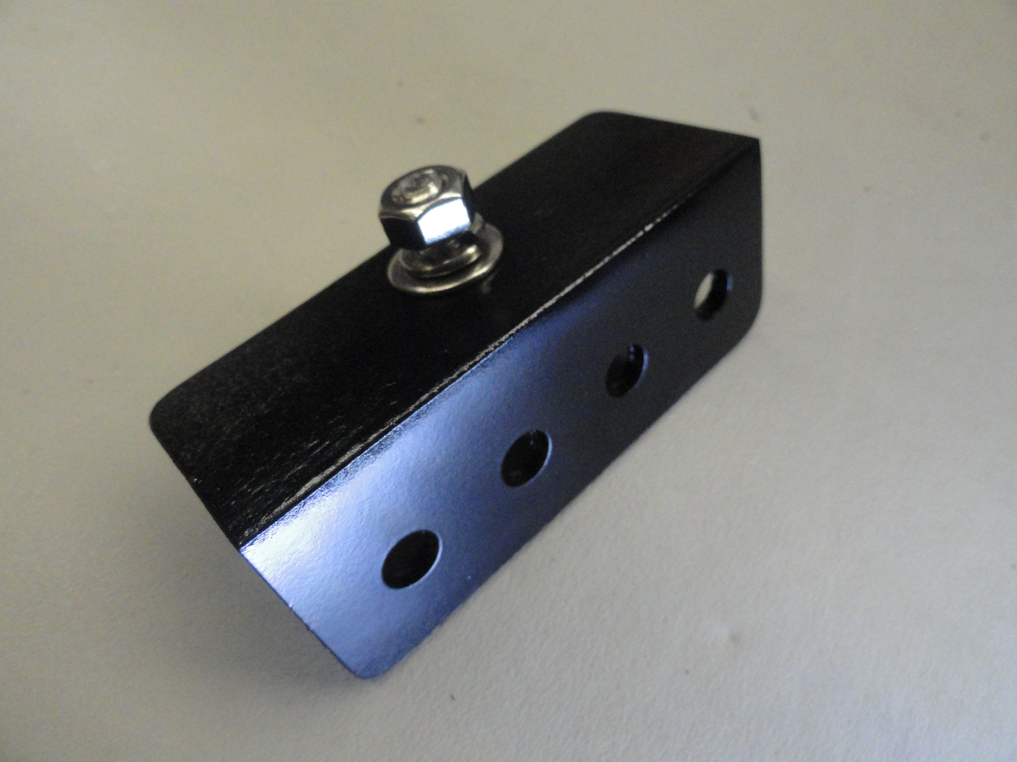
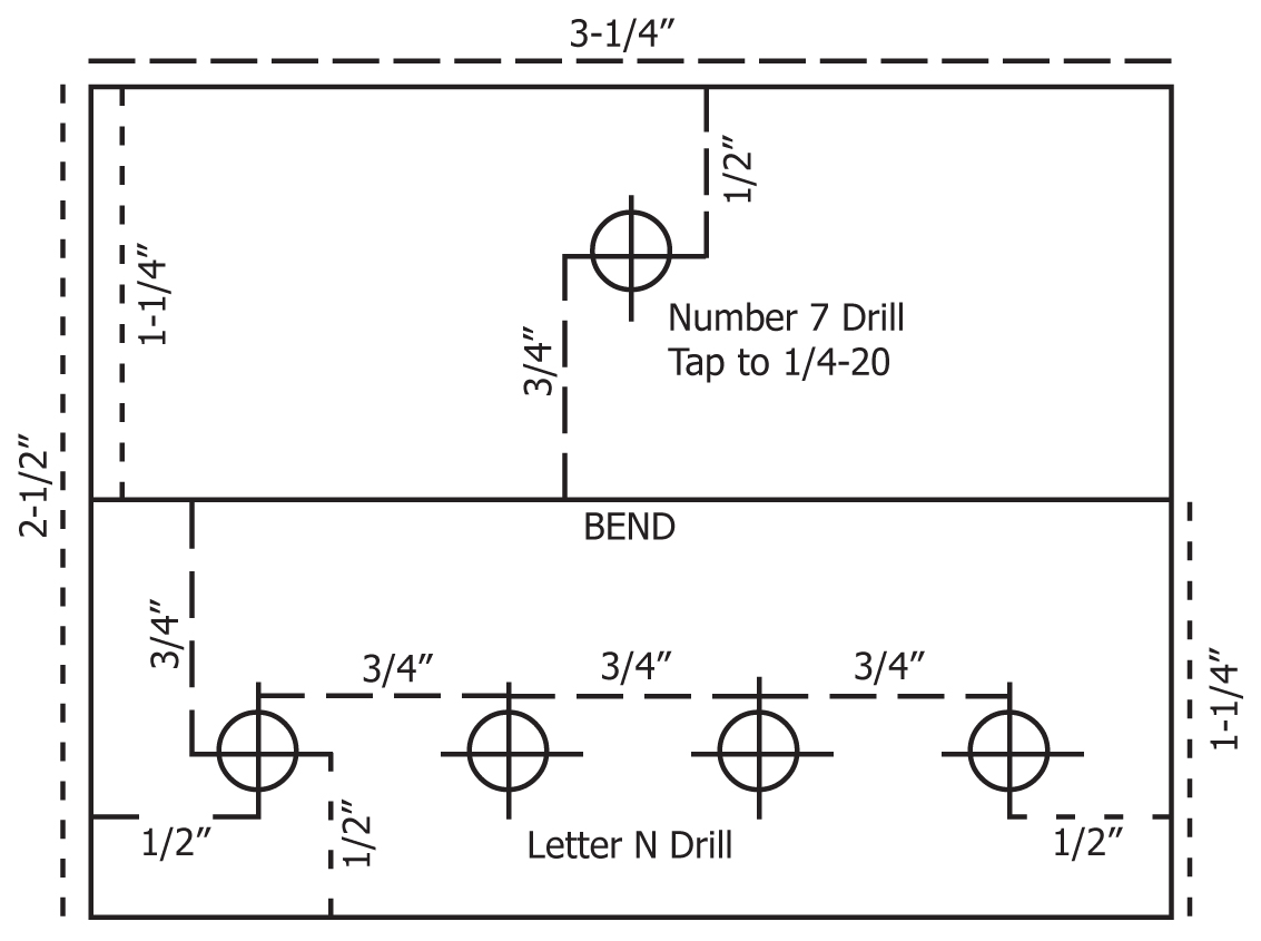
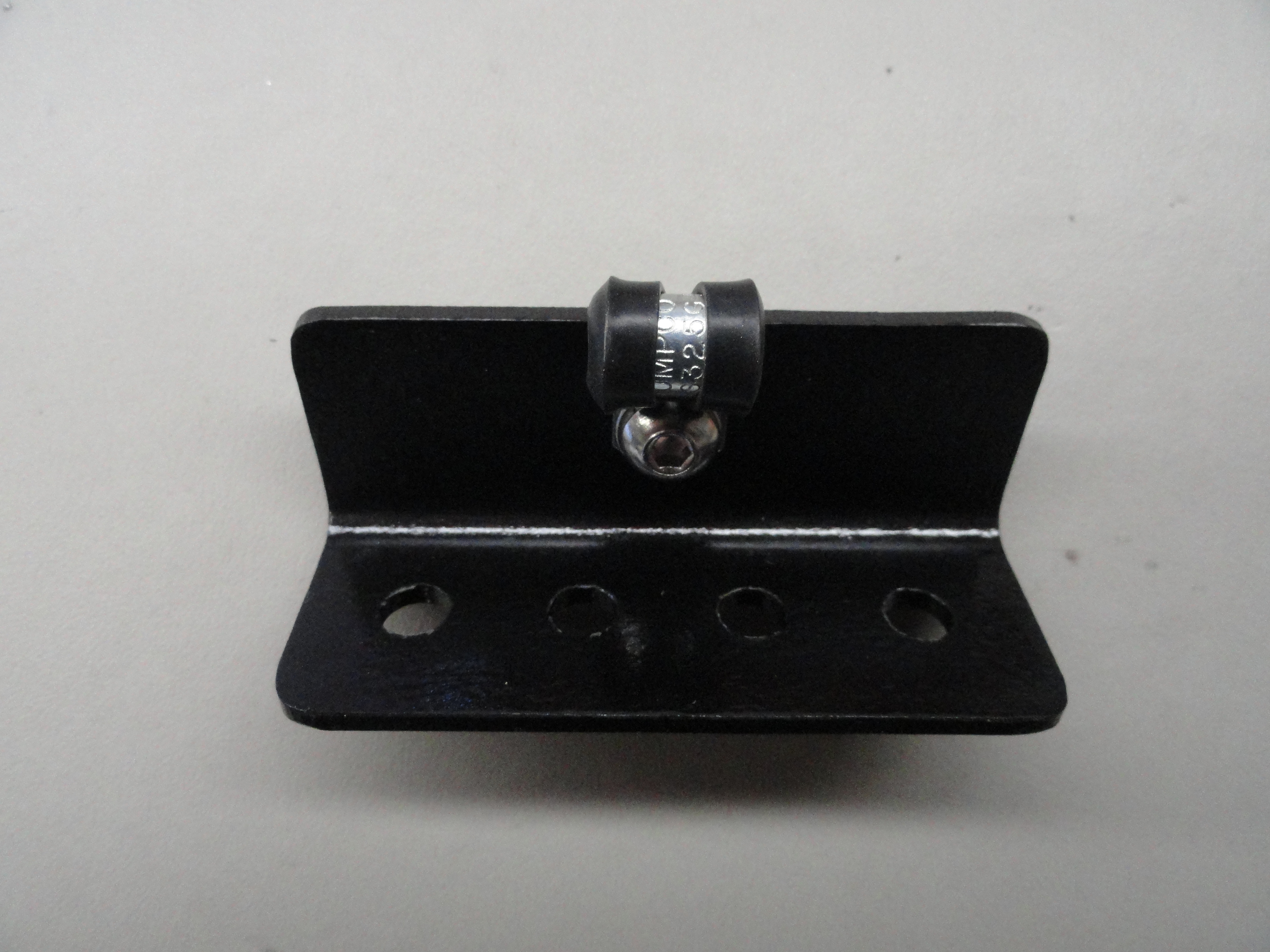
This bracket is made out of 2 inch Angle Iron with 1/8" walls. Cut to 1-1/4" from the bend on both sides, and 3-1/4" in total length. The idea is to mount this under your dash in your preferred spot using a single 1/4" hole. The bracket is tapped so that the stainless steel 1/4-20 x 1-1/4" bolt can attach very solidly. To preserve it, I use etching primer, then GM Low Gloss Black, then Clearcoat. The holes that are chosen work for the LED lights that I chose for the project. A letter N drill bit works best for the LED lights, then the lights have threads, locks and washers to fasten them to the bracket. Included is a 1/4" Adel Clamp for securely fastening the wires. Round the corners off as you wish for style.
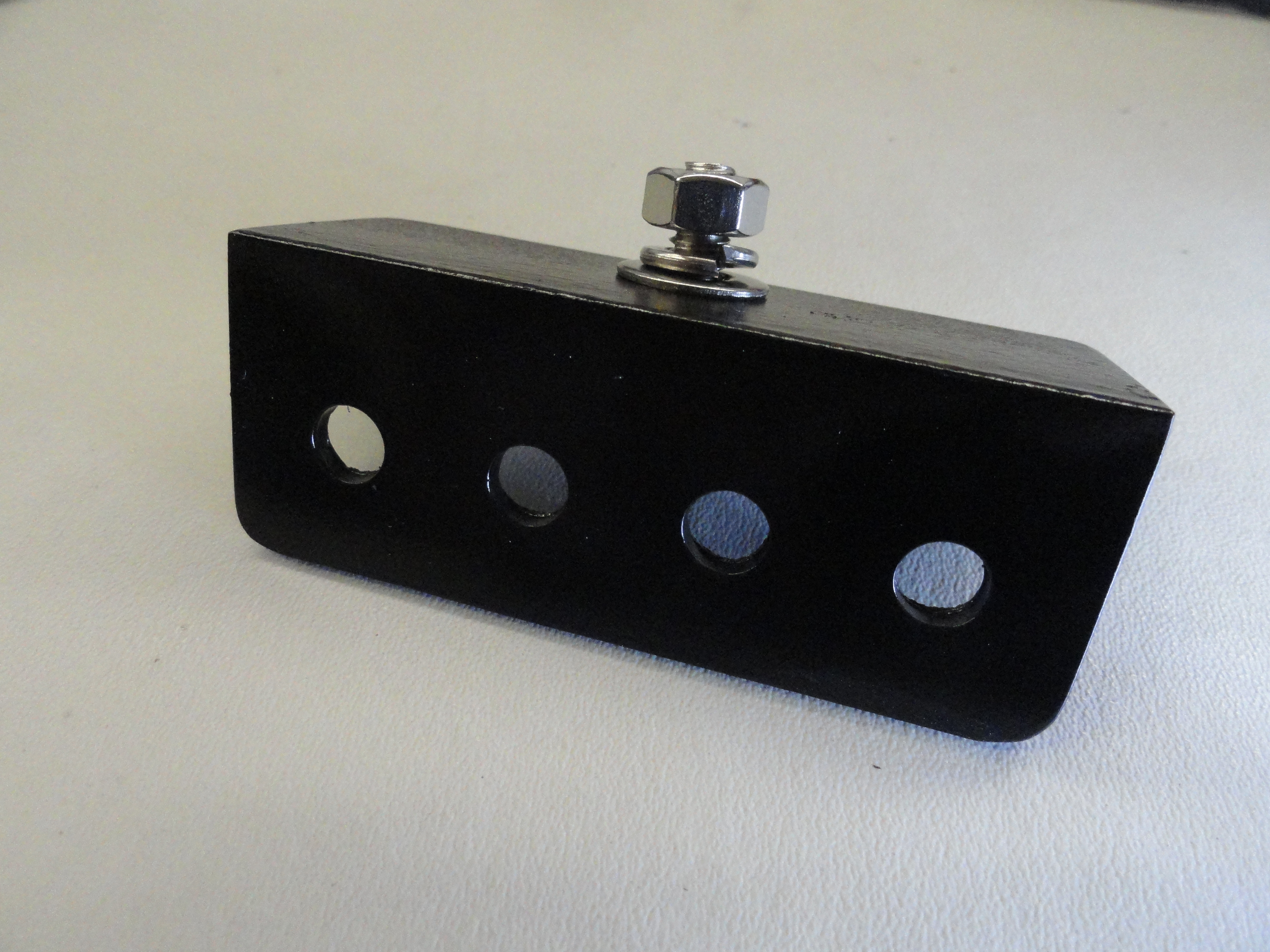
Here are a few more pics of the bracket. To wire the lights in, you want to be EXTRA careful in routing these LED lights because they are very fragile and the leads break off rather easily. Route the two left wires through the Adel Clamp one direction, and the right two wires the opposite, then tie wrap them firmly in place leaving plenty of slack so pulling on the wires does not damage the LED's. Once the LED's are in place, use Red Terminal Male Connectors on the ends for easy connection to the black box. Of course with the invention of shrink wrap, we can make it look really clean.
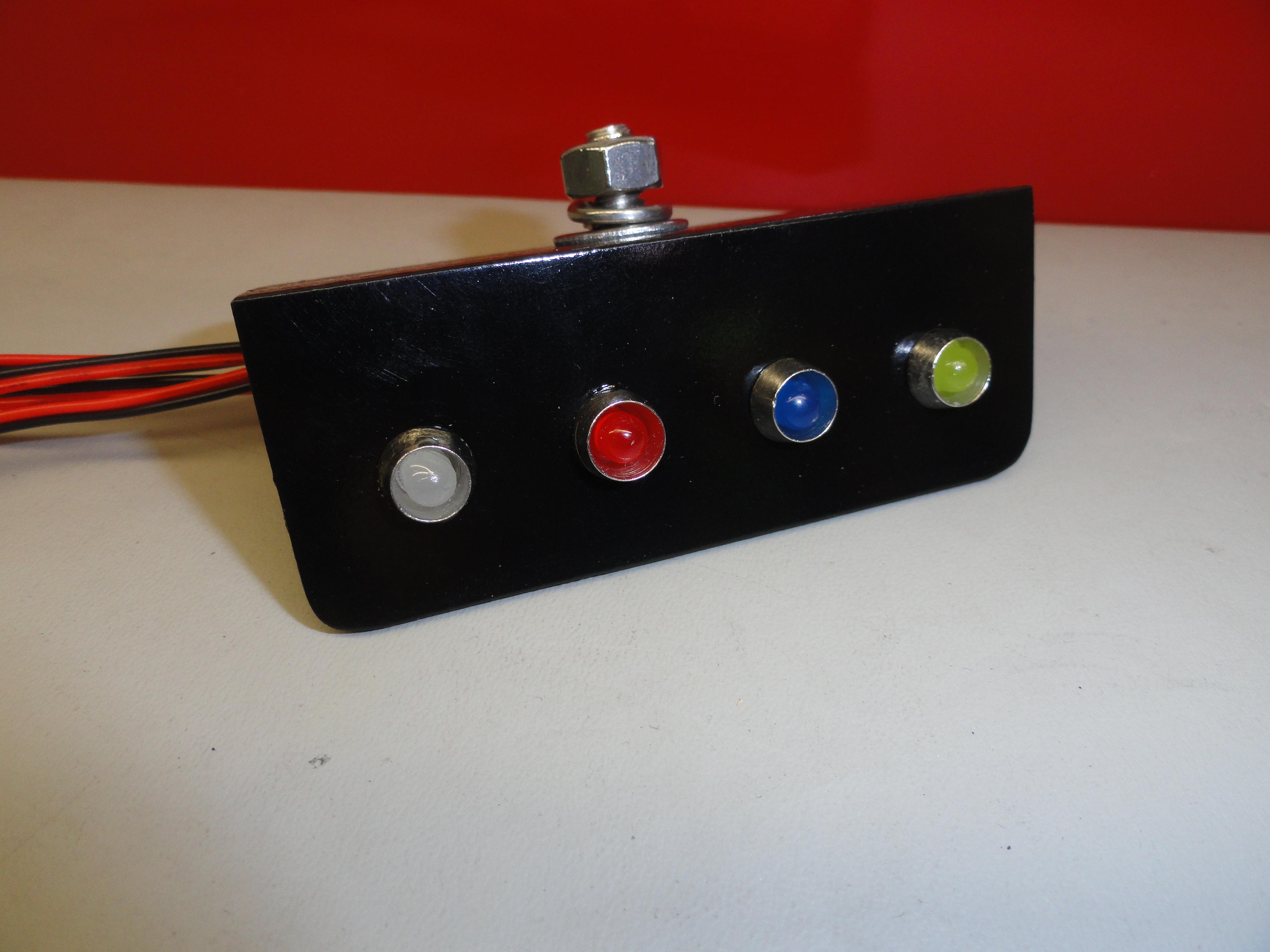
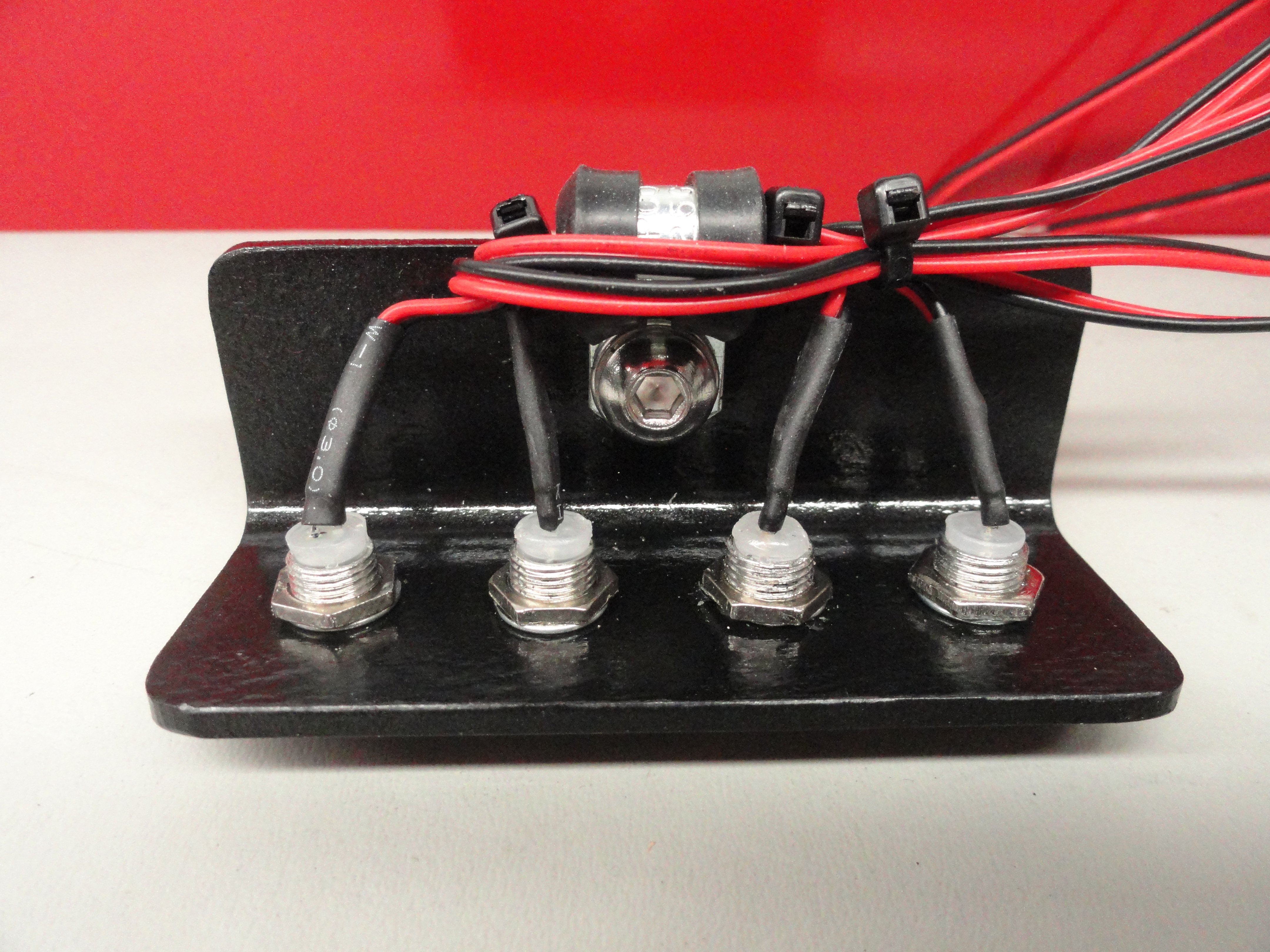
Here are the two with everything assembled ready for connection to the Black Box. No stone unturned as far as quality. The stainless steel studs and hardware will keep it secured forever. I chose these particular LED's because they have a Fifties look to them complete with Jet Engine Exhausts with lights in them! They will not look out of place in anyones ride. What's more, they will be one of the most useful systems in your vehicle. This bracket and the one below can get anyone to thinking how to make a custom bracket for their particular tastes.
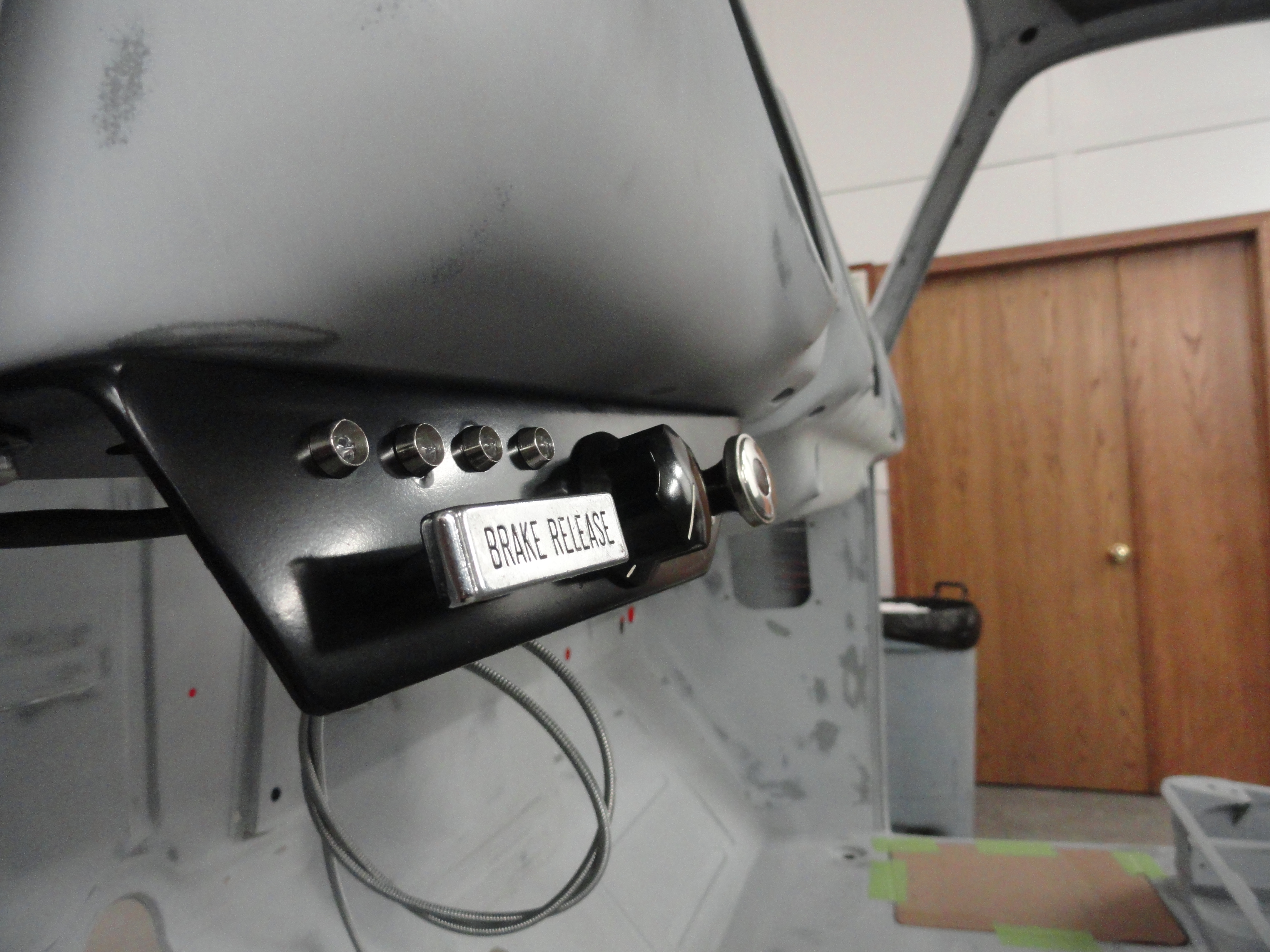
When you look at that side of the dash, there is a lot of wasted space and with two brackets coming down to accommodate the Defroster Cable and the Parking Brake, it looks disheveled and a little barren. So, I designed a bracket that took Queue's off the drop-down part of the dash in the center. I measured where that center drop-down slopes off and made the new bracket an opposite twin. This way with Interior paint on it, it will almost look like it belongs there. I then chose a bolt pattern to fasten it that would make the dash more solid as well as those things that are attached to it. I used 1/8" (the same as the vehicles frame) for strength. Nothing flimsy about this solution!
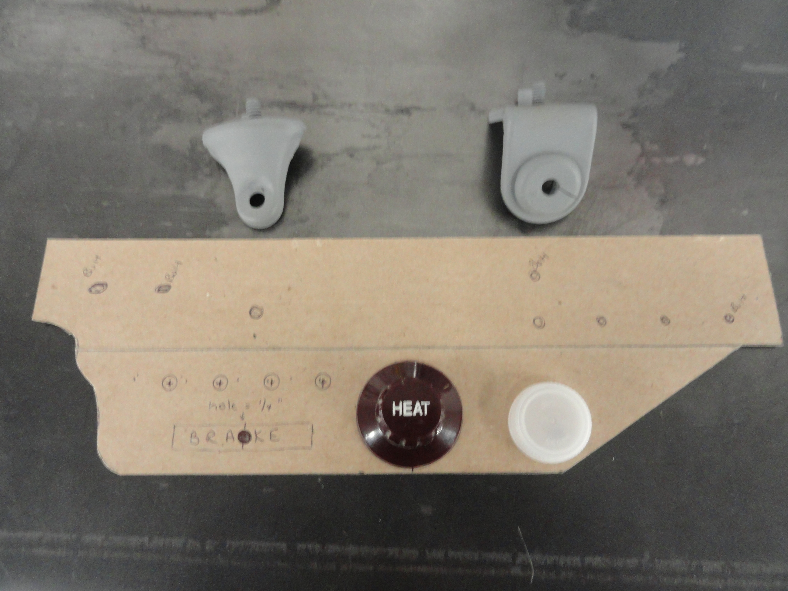
The Parking Brake Release has to be in the exact same spot as it was with the original bracket, so I kept this in mind when deciding on the layout. Nobody wants a Defroster Cable that is in the way, so I put that nearest the Steering Column and left the center of the bracket for a Rotary style Heater Switch. This is because the Stock switches are not compatible with 12 volts and after 65 years, they are wearing out. The replacements are all rotary style and we have a new upgrade to your Heater system that takes full advantage of this by giving you a rotary switch with no 'positions'. The switch just turns smoothly to give you every fan speed the motor can generate. More on that later. The four small holes above the Parking Brake Release is for our Warning Lights. These are small colored LED's that will be under the dash enough to be subtle, yet shine brightly when a problem occurs.
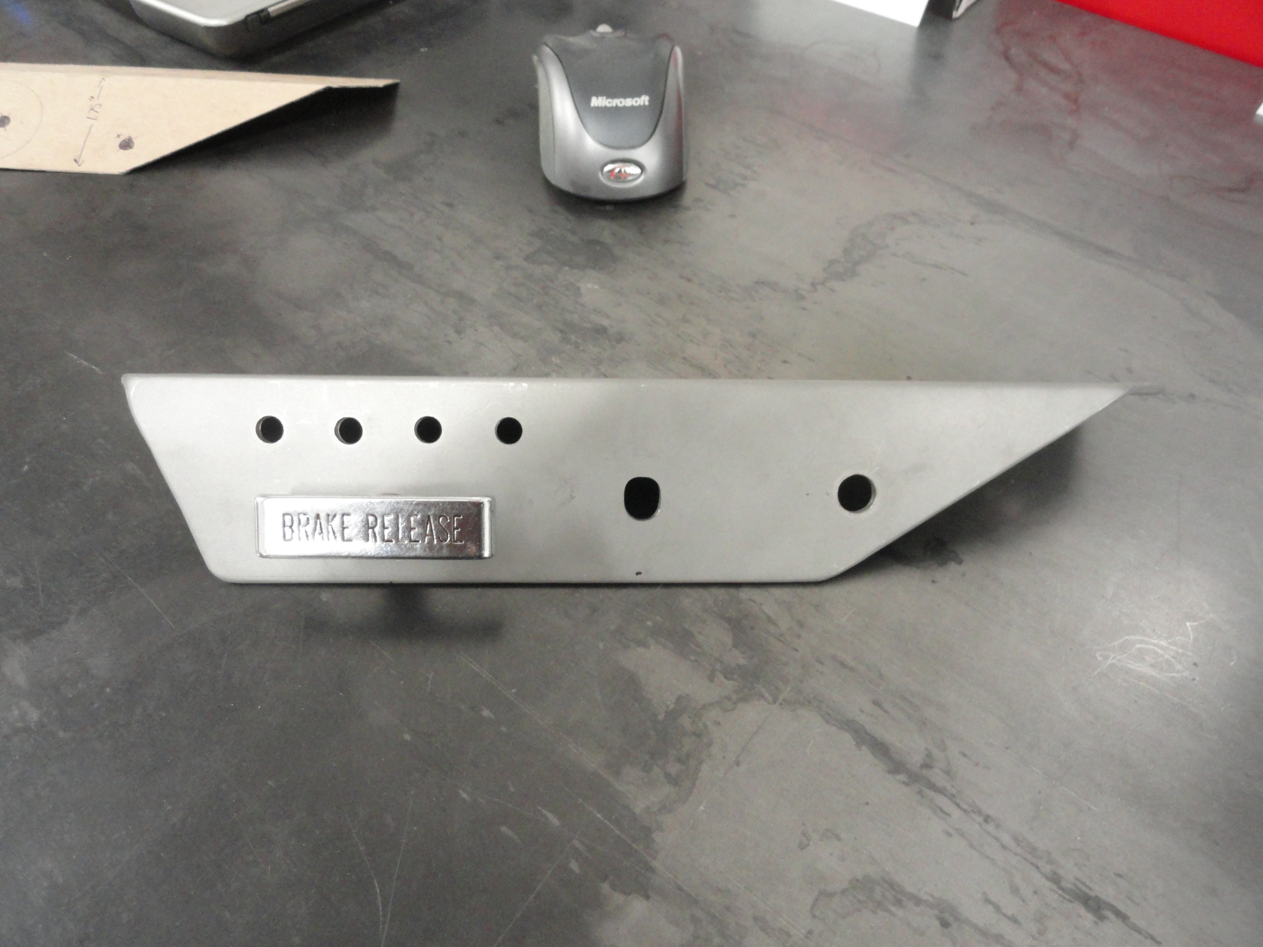
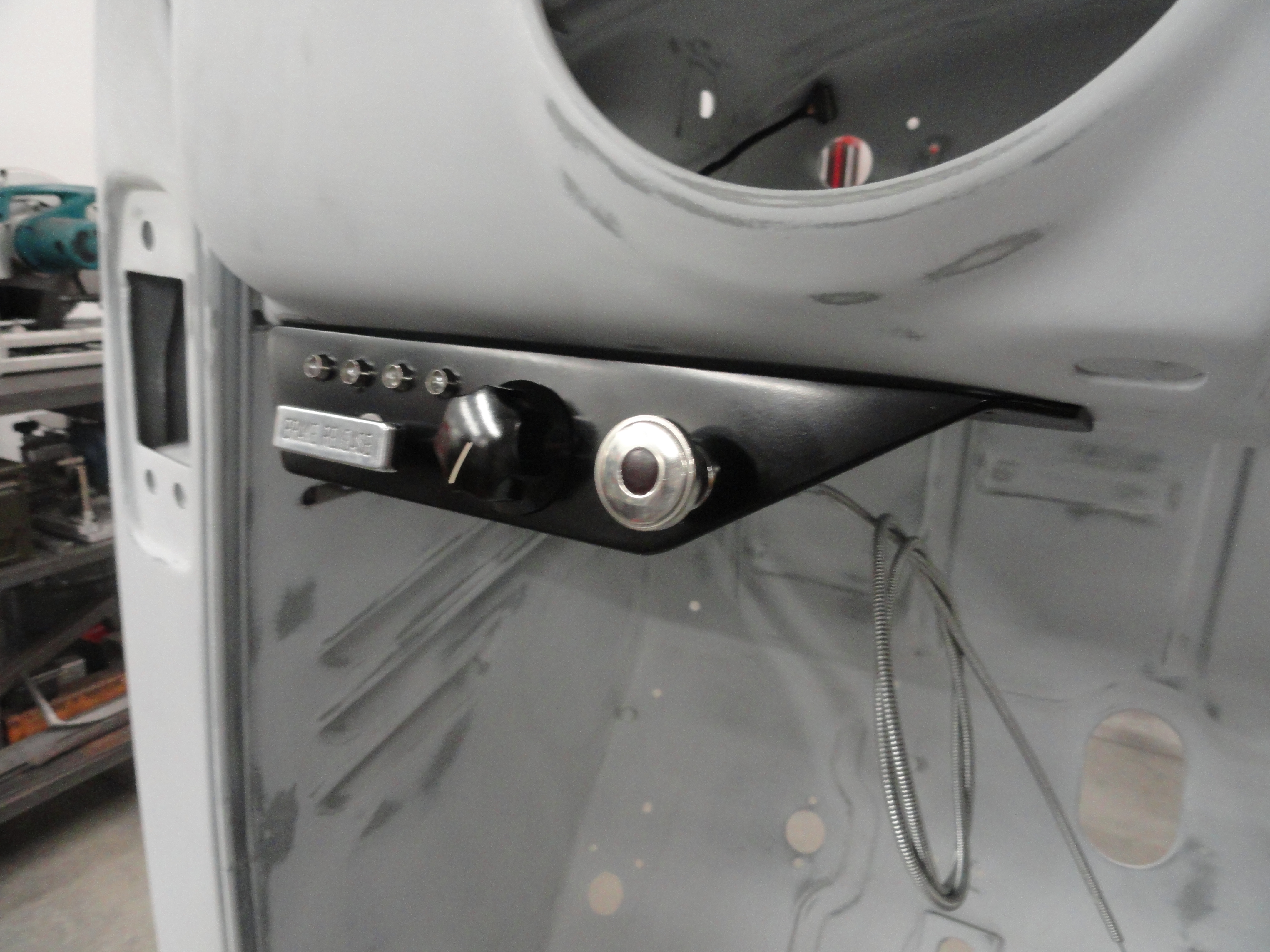
As you can see, the Heater Switch hole is centered and made for a nice heavy solid 1.5 inch knob. The Defroster Cable mounts exactly across from it so that everything looks uniform. The holes will be custom for each individuals needs when ordering this plate, so don't worry if yours is different. For example, not all AD era Trucks had Defroster Cables. First though, understand you can make this yourself out of a 10-3/4" piece of 1/8" by 2" Angle Iron. The top mounting holes (shown) were chosen to make this piece mount very solidly in place. It uses the two dash anchor bolts on the end and then a few carefully chosen holes that are in the stock locations for the rest of it. Lets see about making this plate...
As I stated earlier, start with a piece of 1/8" x 2" x 10-3/4" Angle Iron. This is the perfect choice for this because it will mount flush with the back of the dash while providing just the right amount of overhang for our Controls. In an earlier picture you could see how I use a piece of chipboard and fashion it as a template. Then you have to look at what is readily available in metal stock and compromise. In this case, I learned that the 2 inch Angle Iron was a better idea than my template that was only 1-3/4". It also turns out that a 90 degree bend is about right. You can't take any of this for granted, rather, test it and see for yourself. So in fashioning this dash bracket, I did some drawings and made some notations that I will share with you here.

Very important you follow the steps outlined here. The measurements are taken from a square piece of 1/8" Angle Iron so to measure properly, do not make the cuts first, rather, drill the holes first. The Parking Brake Release Knob has to be in the exact same place it was when mounted with the stock bracket so that is the only non-negotiable aspect of this. Another consideration would be how long your Defroster Cable is but in this case, we are mounting it closer to the Heater, not further away. Part of a good tool arsenal is the 115 piece Drill Bit Set. It has the Wire Increments, Metric Increments and the Standard Increments. Some of the stuff we do requires just the right Bit. With a Drill Doctor, those bits will last you a lifetime! All of the measurements you see here are from the left side of the piece and measurements are to the exact center of each hole.
The measurements for holding the piece firm to the bottom of the dash are NOT reliable! What you need to do is clamp your piece of angle iron to the dash, then mark the holes yourself. The reason I say this is because I do not trust that each cab was made using the exact same templates since there were many factories at the time. To be safe, mark them yourself through the holes with a fine Sharpie, then punch the center of the mark for drilling. I put these numbers here so you can verify your numbers are close. The third hole from the left is where the tab that was part of the original Defroster Control used to be located. The last hole (right) is the last hole nearest the Steering Column. The two on the left are the standard 5/16" bolt holes used to hold the dash on, then 1/4" bolts for the other two. I like how solid it is. It gives you a sense that it belongs there.
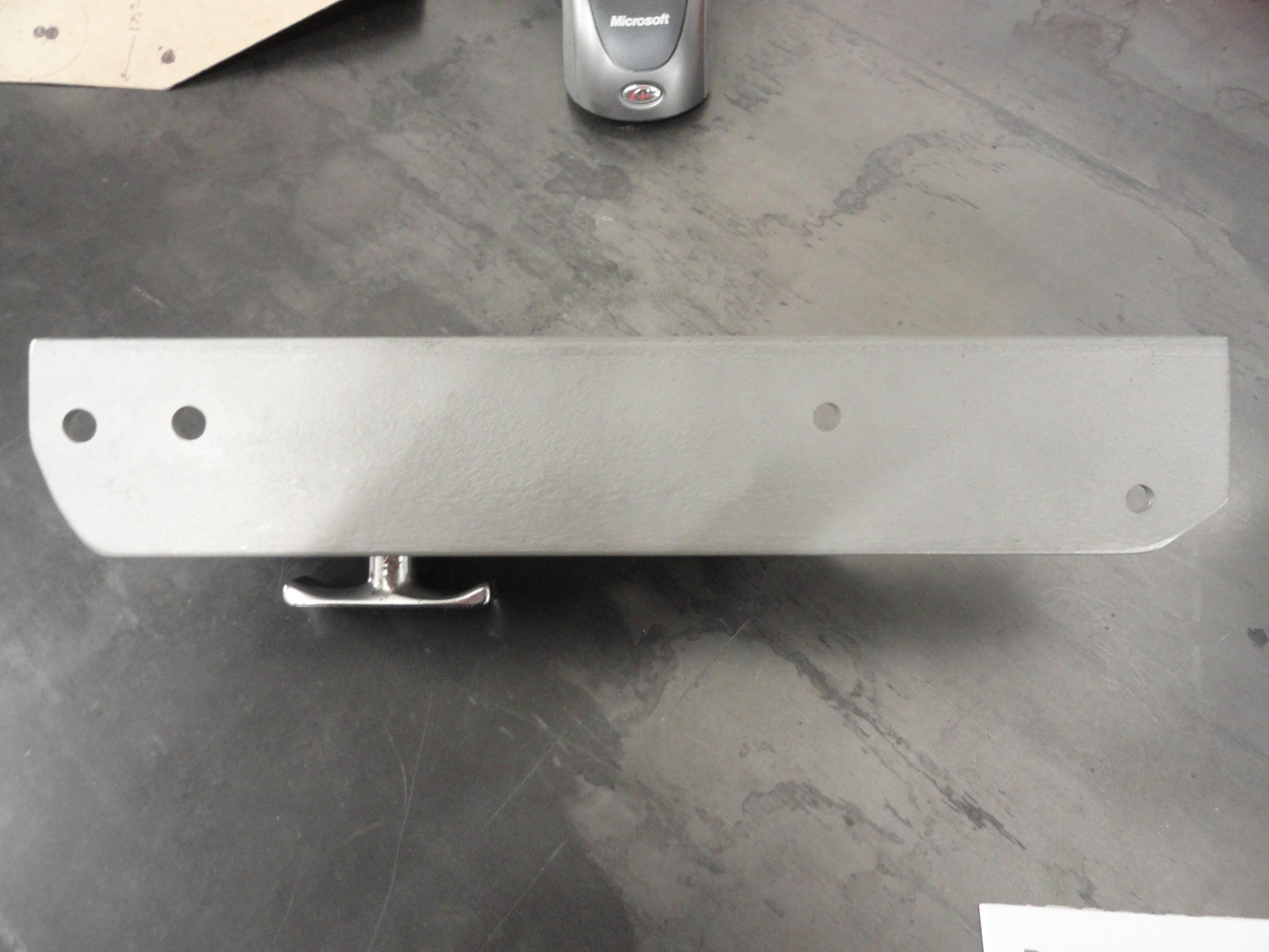
To make the front face contour look the same as the center of the dash was a big consideration. I wanted this to look like it belongs there too. It doesn't quite but it's as close as you can get with a flat piece of metal. We need it flat to fulfill its purpose so we will have to compromise on the fact that it is not rolled under like the center of the dash. The numbers here make the cuts from top to bottom come together so you can finish the corners with a grinder to give it a more rounded appearance. The right side angle was done to replicate the dash centers same contour and also the distance from the steering column. Once we have the geometry correct, we look to see how much room is left for our purposes, then design the knob placement the best we can with the real estate we have.

The mounting surface just needs a few cuts to make it look right. The reason for the left side needing this angle is because of the way the dash is contoured near the door opening. The right side is because that part is unneeded and happens to be the same angle as the front face so we can make this cut from the front to the back all in one cut. To do that, lay the angle iron on the table flat (upside down V) and continue the line from front to back. You could do the same thing on the left side without penalty too.
The LED lights is a large part of the reason for this exercise. Placed here, they will be within view and not look too conspicuous. They are LED so they will last a long time, but in any case they are easily replaceable. Our control box will be placed under the dash on the upper left kick panel out of sight and that is where the audio alarm will be located. Looks like things are coming together nicely! It looks really cool even if I do say so myself.
First we have to find a place for the Sensor. We can't use the original location for the Water Temperature sensor since it is already being used for the Water
Temperature Gauge. Since the sensor needs to be in water, our choices are very limited. After thinking about it, the drivers side engine drain seems to be the
best choice. With adapters, we can use it as a drain AND use it for the Water Temp sensor.
No, that doesn't work! I am putting failures here so you can understand what has already been tried. No sense in doing the same thing yourself. Turns out after
letting the engine warm up thoroughly the maximum water temperature I can get out of that drain port is about 150 degrees. The same sensor placed in the Head
port goes to 180 degrees. Putting it in the Drain location would be unreliable and off by about 30 degrees. Back to the Drawing Board.
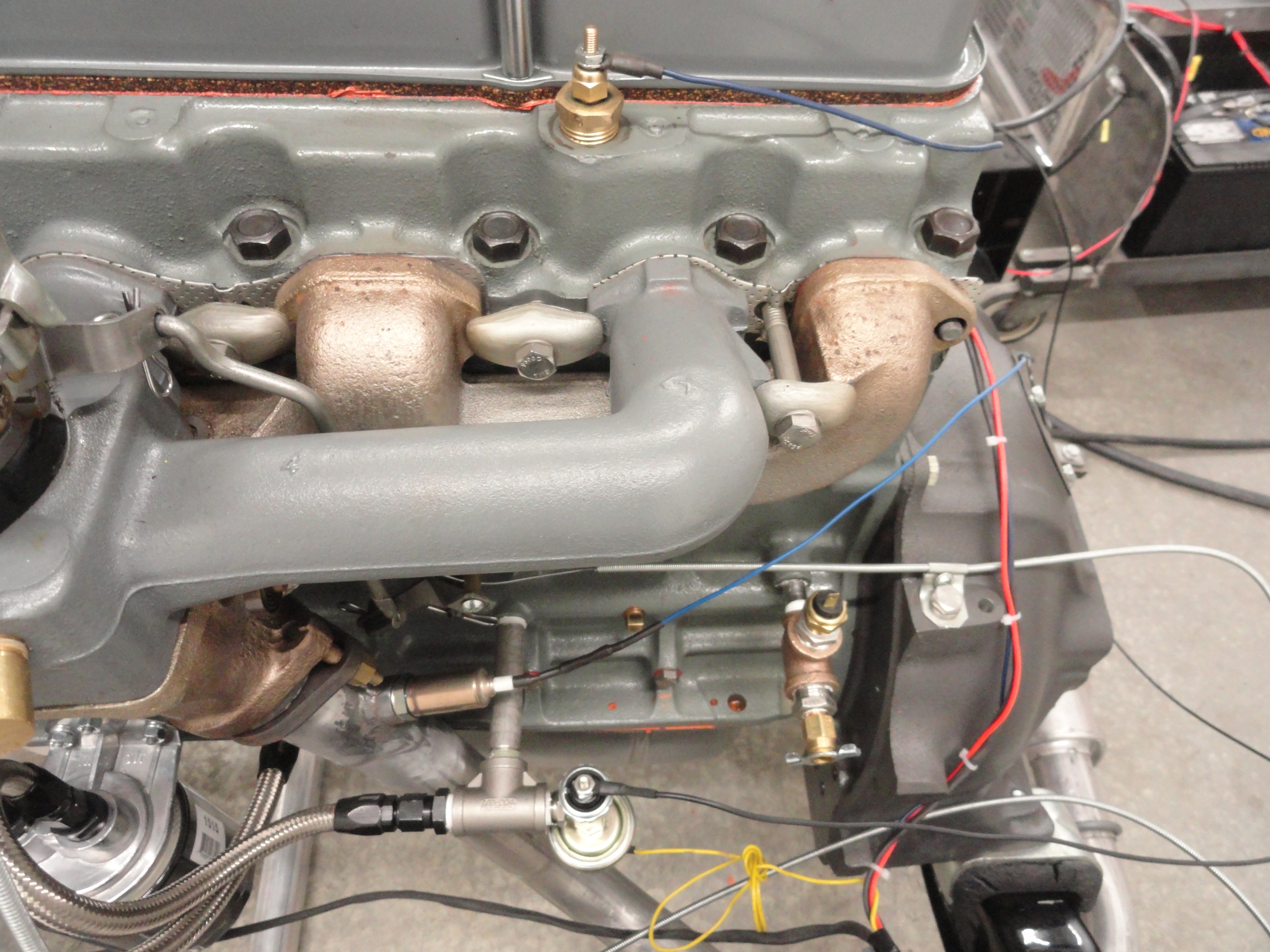
So now after taking some IR Thermometer readings at the water pump, I want to try to put it in the Thermostat Housing Port used for connecting the Heater. You can
still connect your heater hose and even the water control there, but you want to put the sensor in first to ensure the temperature is the hottest it can be. Doing
all this testing means draining the water sufficiently each time but part of the process.
As far as interference with the lower hose or anything, there is no conflict.

In searching the Internet for information concerning temperature sensors for automotive use we found an interesting project to help us better understand how this more modern technology works. We found the Automotive Grade Thermistor to be the central component. This is basically a Thermal Resistor that senses temperature changes and varies the ohm value accordingly. We ran across a design plan from ElectronicsNMore. They put out free information on Electronic projects of all kinds. If you are interested in that sort of thing I would encourage you to check them out.
What was intriguing about this project was it does almost exactly what we want. It lights an LED when a very particular temperature is reached. It also has the benefit of supporting Piezo Buzzers for an Audible Alarm System. Lets put this thing together and take it for a test drive! Here is the Schematic of this very simple project. I like how few parts are needed. The fewer parts the better for reliability. This project will not be incorporated in our end design because we need a relay instead of lights, but it's a very good project to better understand the technology. Relays isolate the circuit and make everything safer.
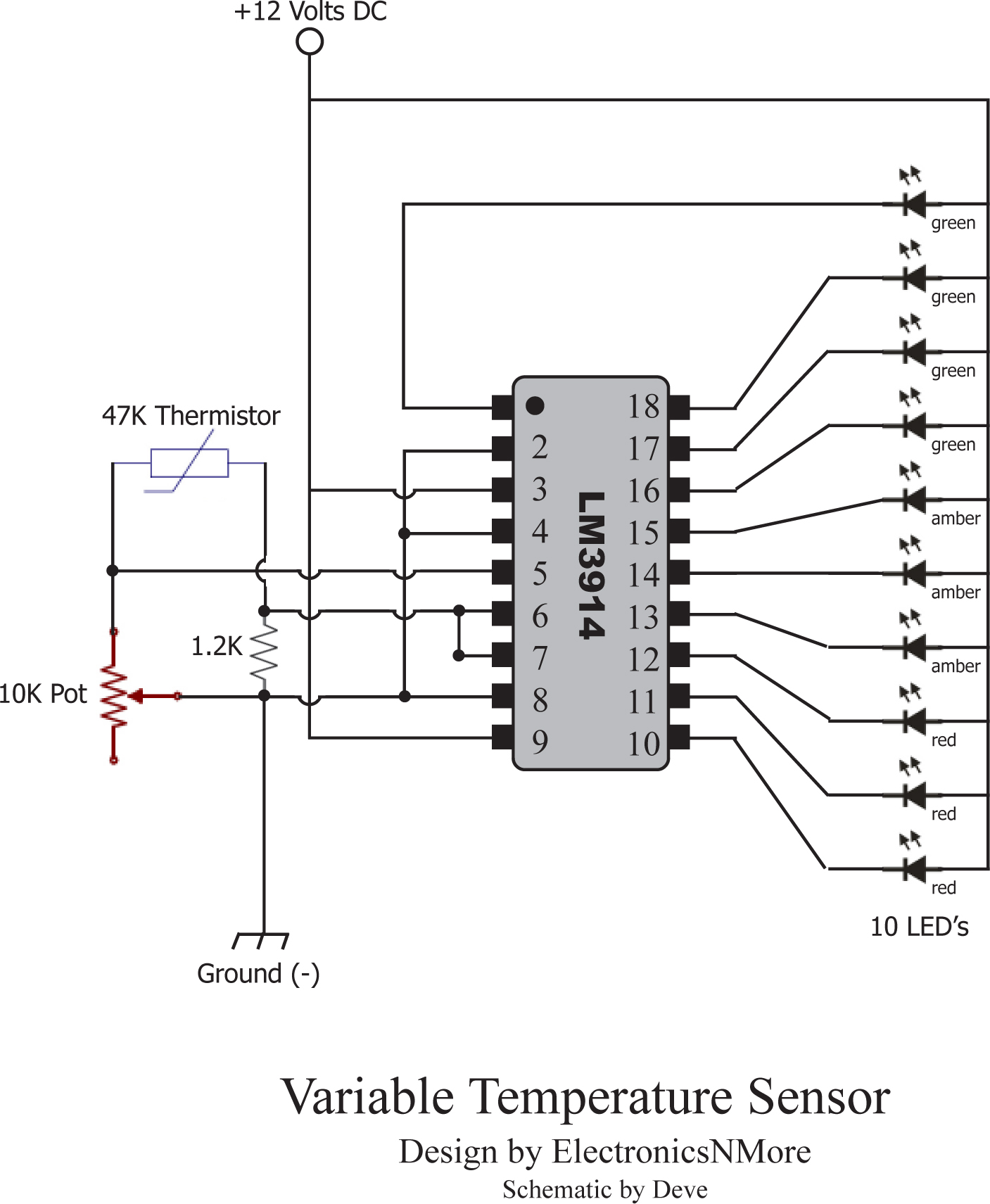
The brains for this project is a Texas Instruments LM3914 Dot/Bar Display Driver IC. It is a 10 step voltage divider and made for this purpose. We will apply 12 volts for this project and it's capable of between 6.8 and 18 Volts DC. Lets get some parts on order! Everything Listed is from www.mouser.com.
Remember, this is a learning project and will not be used for the end design. We are learning how to build a circuit that incorporates all of the assets that are needed to make our system successful. This is a necessary step to better understand how Thermistors and IC Drivers work. This circuit is perfect to demonstrate a few features that we need. The questions we need answered are:
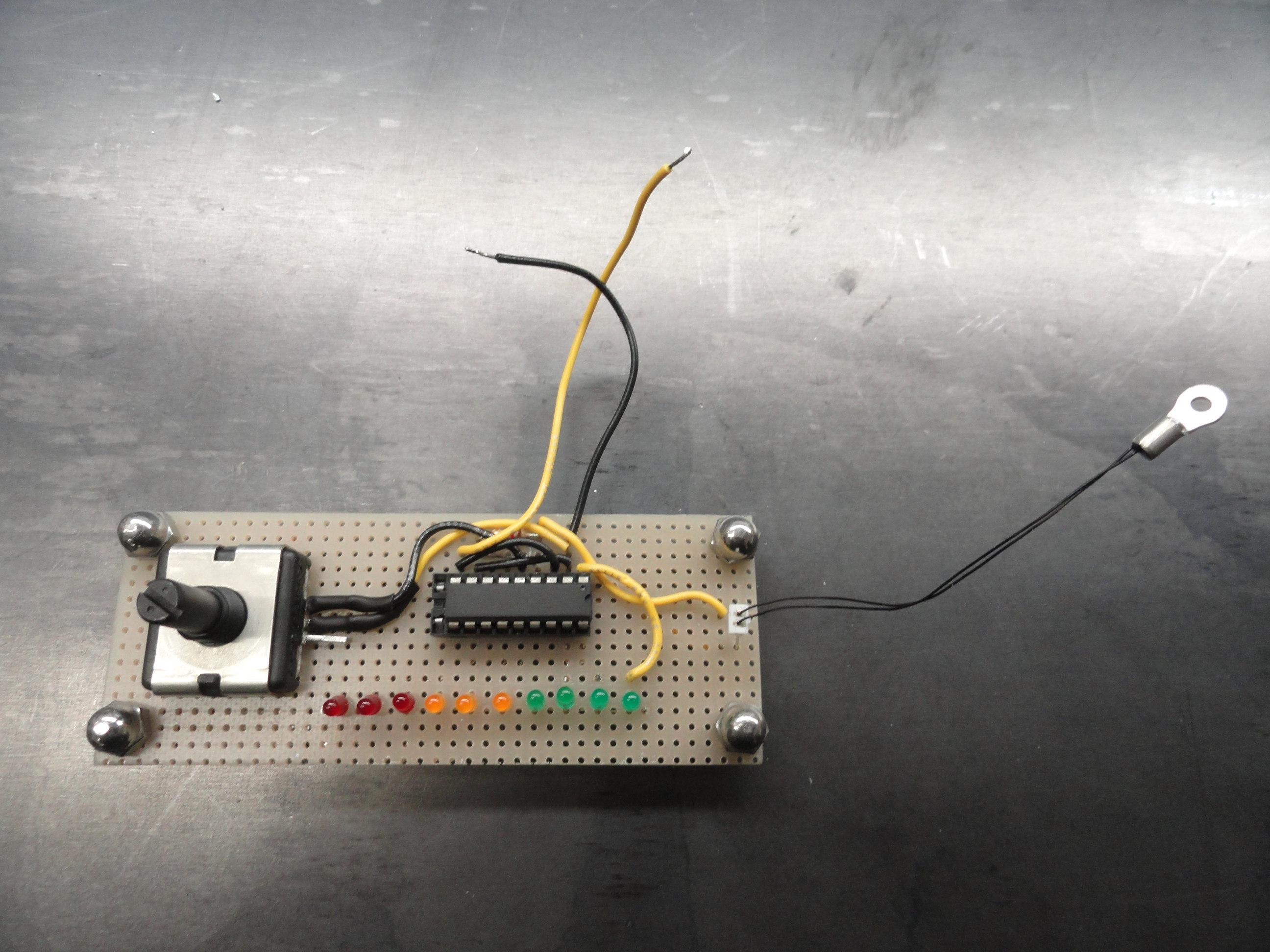
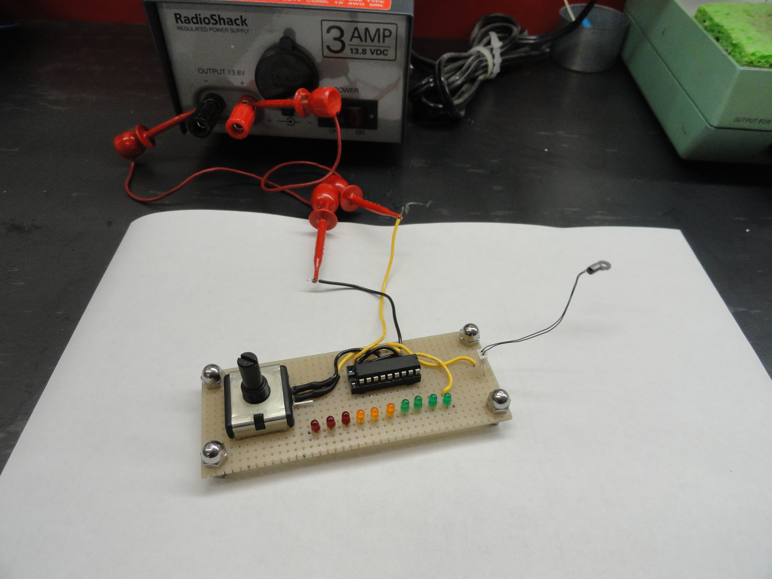
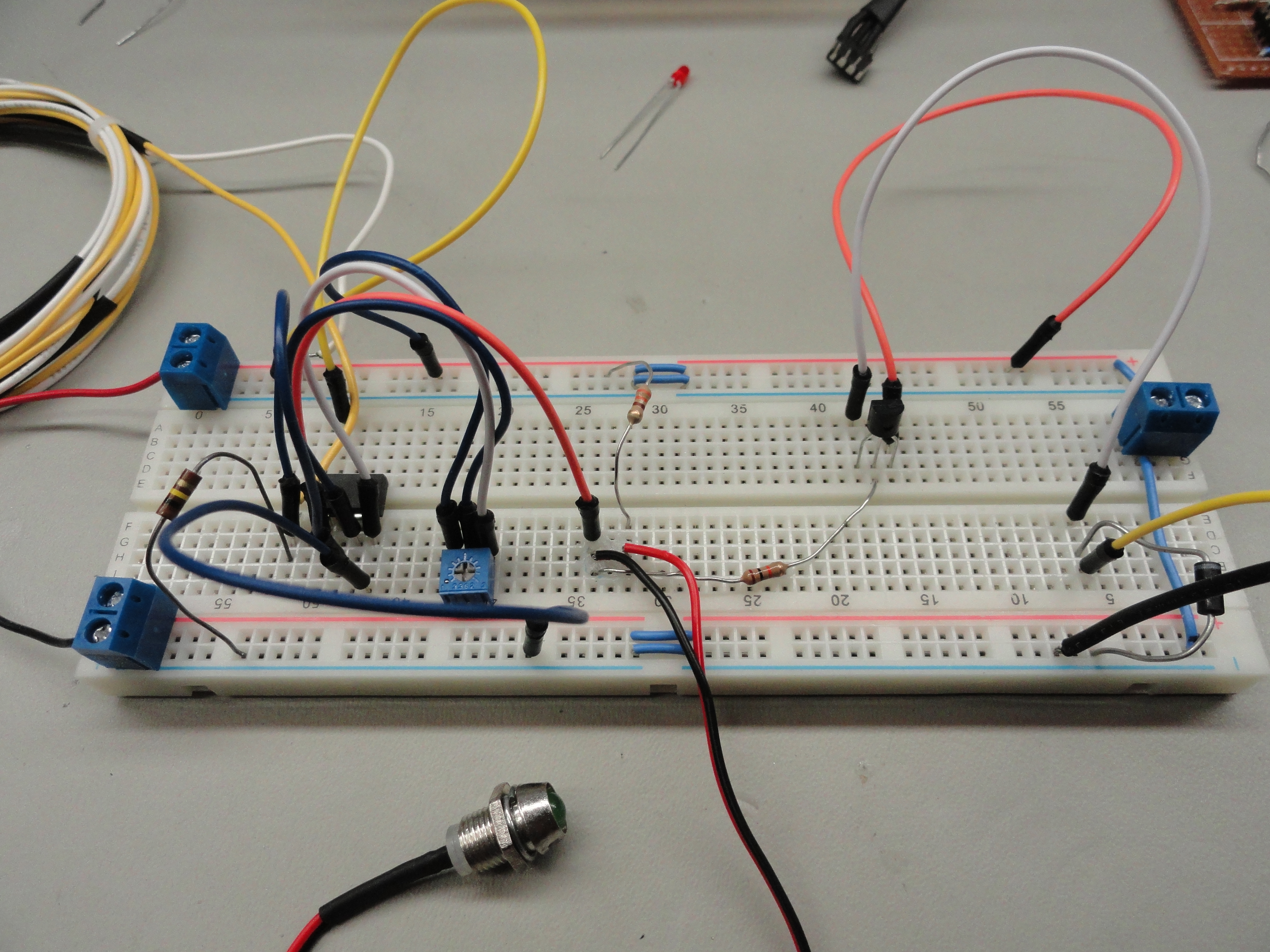
To build this thing you just need to follow the Schematic carefully. Use about 24 gauge hookup wire to make all of the connections. Take it slowly and check, then doublecheck your work. I used a breadboard that has solder pads on one side of it for each through hole. This provided for better anchoring of the parts, but not all that necessary. It DID allow me to use solder bridging on the underside where desired. For any pointers or if you need anything just email me and I will try to help.
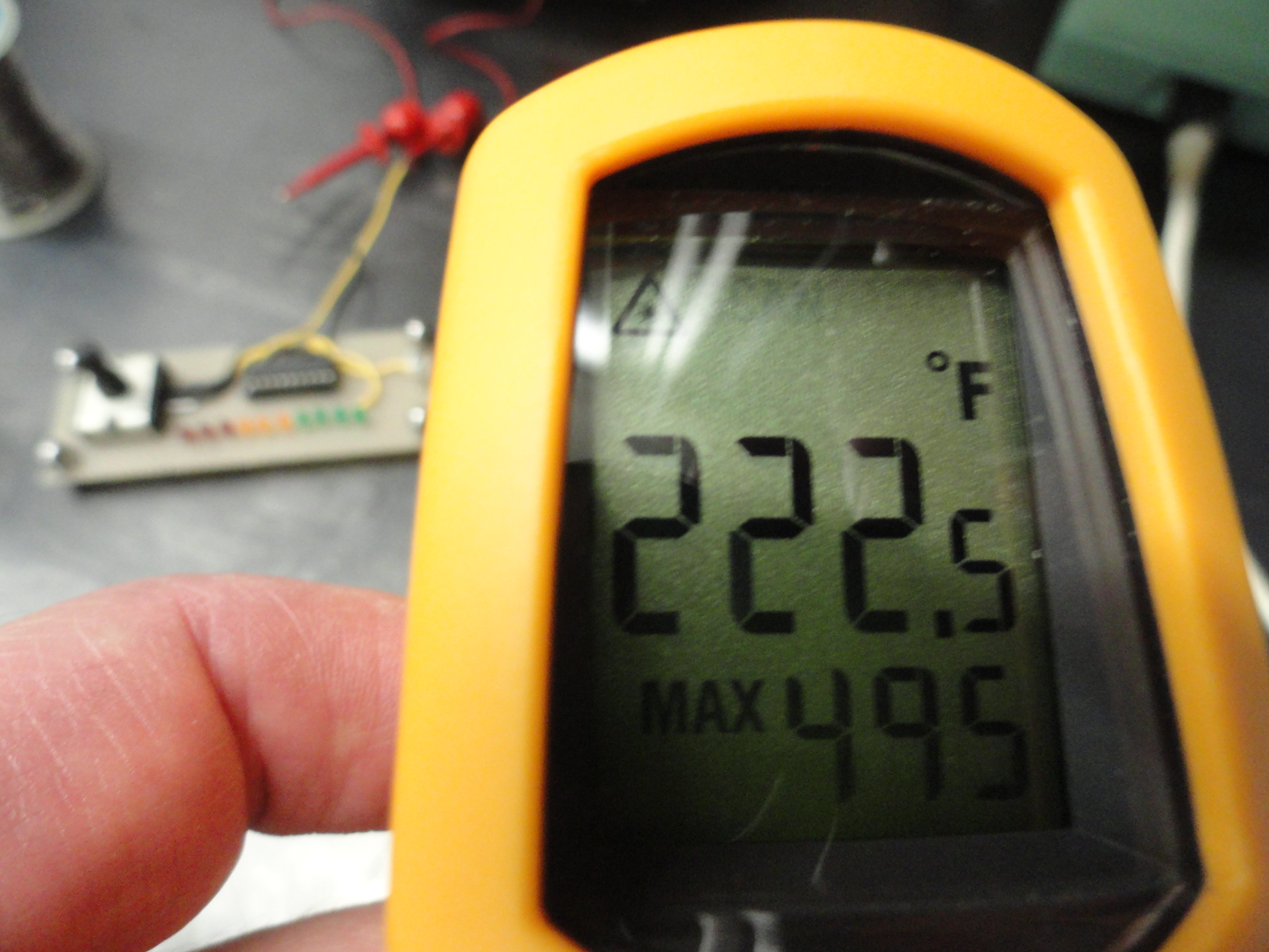
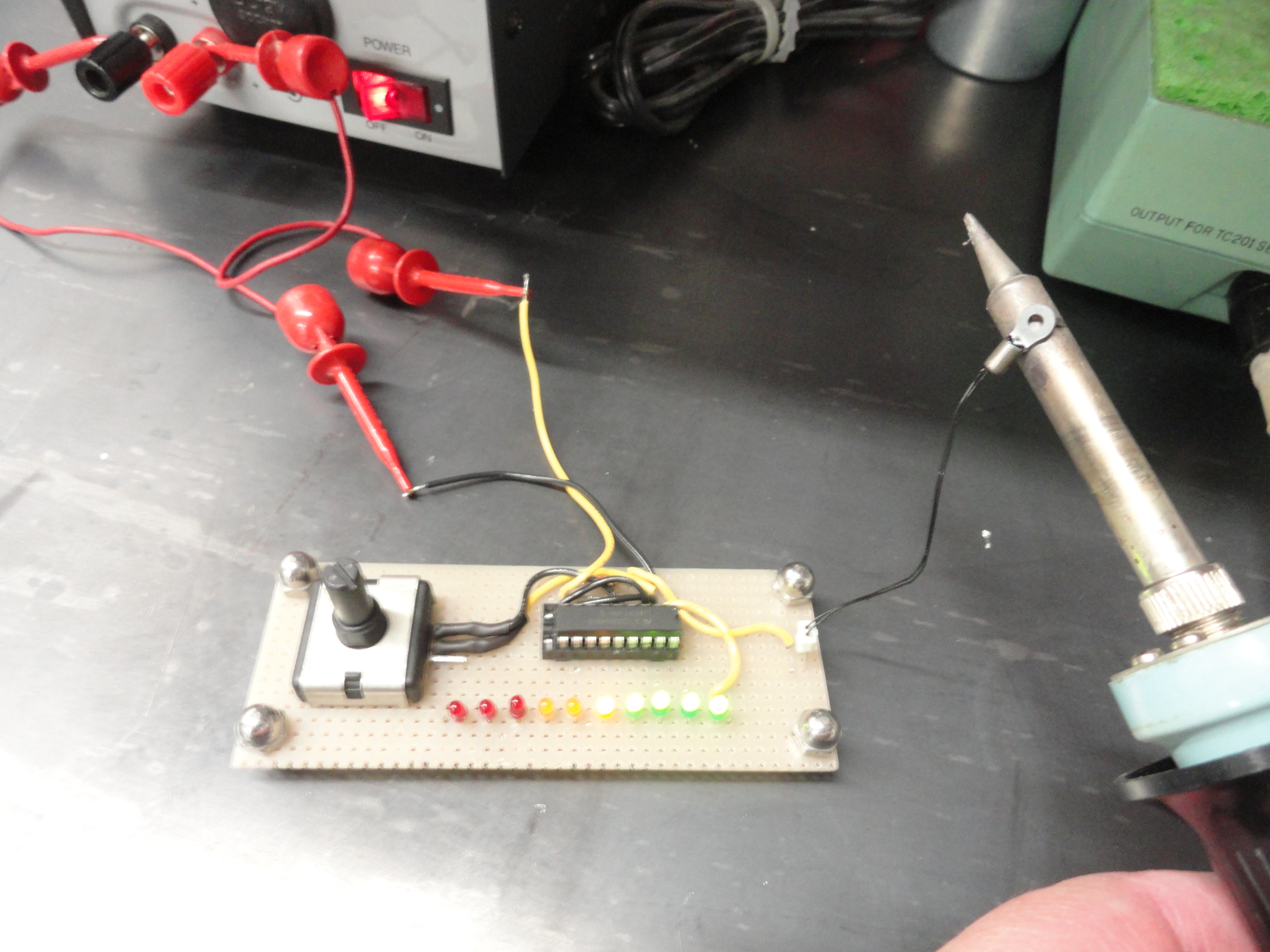
This is a pretty cool little circuit! What's nice about it, is the potentiometer on the board allows us to control the threshold of the lights. So, for example, if I want the first Amber light to represent 220 degrees, I find a 220 degree heat source and touch the Thermistor until the first Amber light lights up and control that with the Potentiometer. I discovered a heat source that is within our range. A Weller Solder Pencil has about 450 degrees (or more) at the tip which is too high, but the barrel of the pencil graduates down pretty slowly so I can mark the temperature using an IR Thermometer at 220 degrees for the test. SO, imagine a Piezo Buzzer (Audible Alarm) in this very same circuit with the LED. We have everything we need to get this done! That concludes coverage of our little test circuit. Next is an attempt to use a circuit that is ready made for our purposes! Let's see where this goes!
Now after understanding this technology better through trial and error, I am ready to start putting this warning circuit into practical use. I found this technology
is used in Automotive applications as a matter of routine in applications like electric fan control and warning circuits. I found a ready made circuit for this
from an Ebay source that could work. This would not be a difficult circuit to make from scratch, however, there may be no need. You will find the water temp
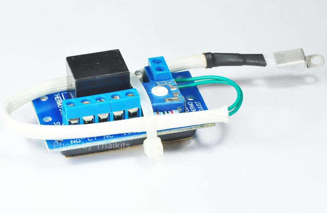
portion of our system mostly ready for use. The supplier is from Thailand so plan on about a four week wait to get the circuit.
I have thoroughly tested this little circuit and it is almost the perfect thing for our purposes. Because it merely energizes a 5 amp relay, it can be used for any
temperature sensitive application.
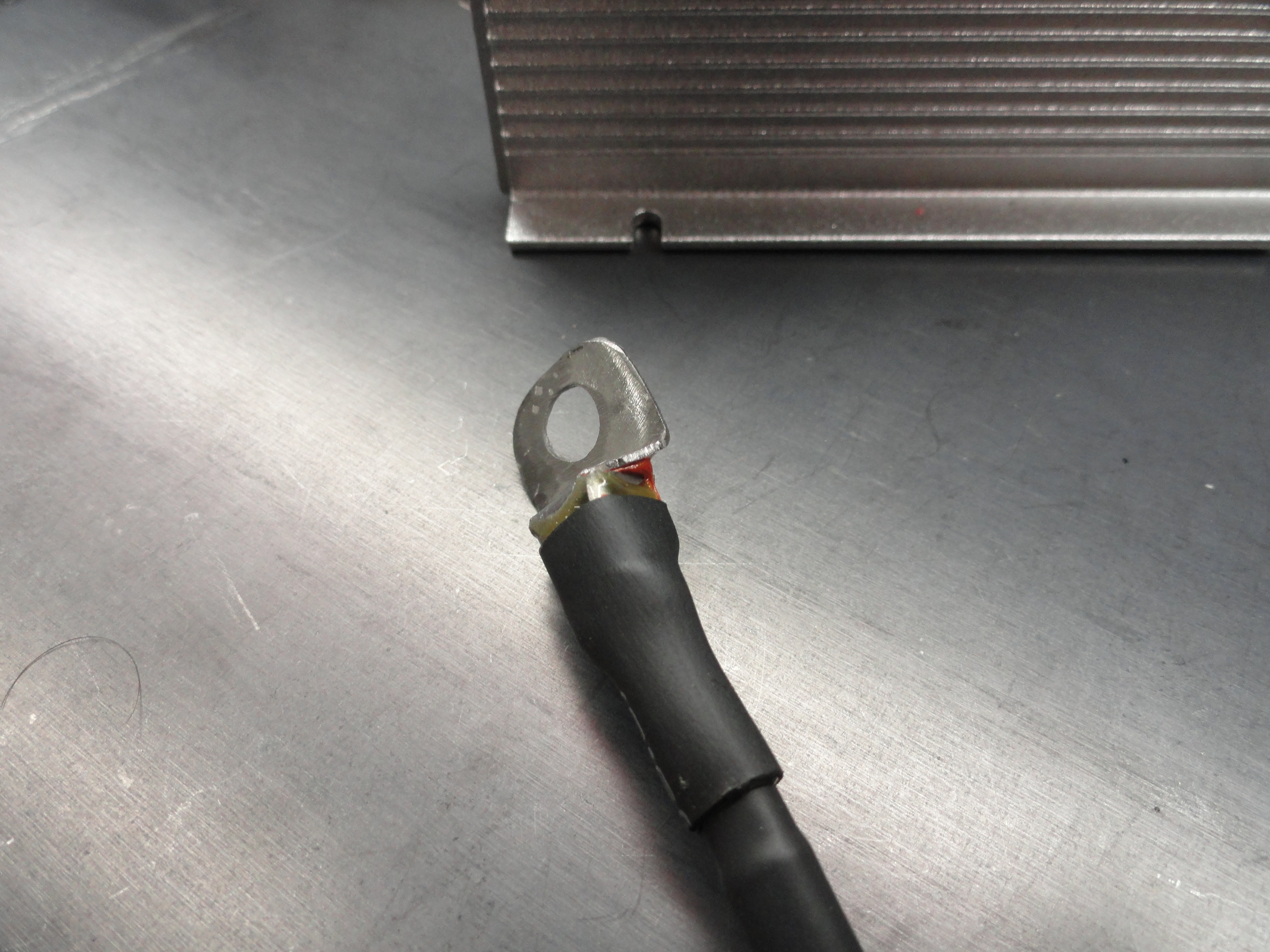
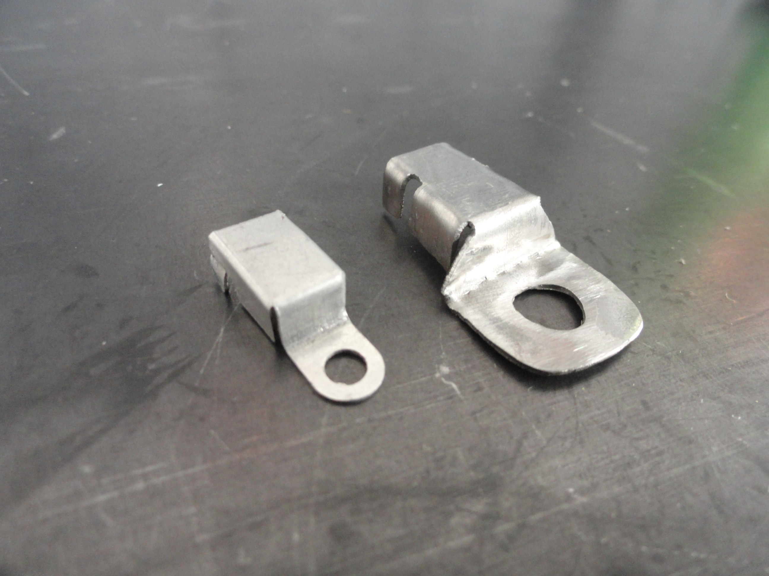
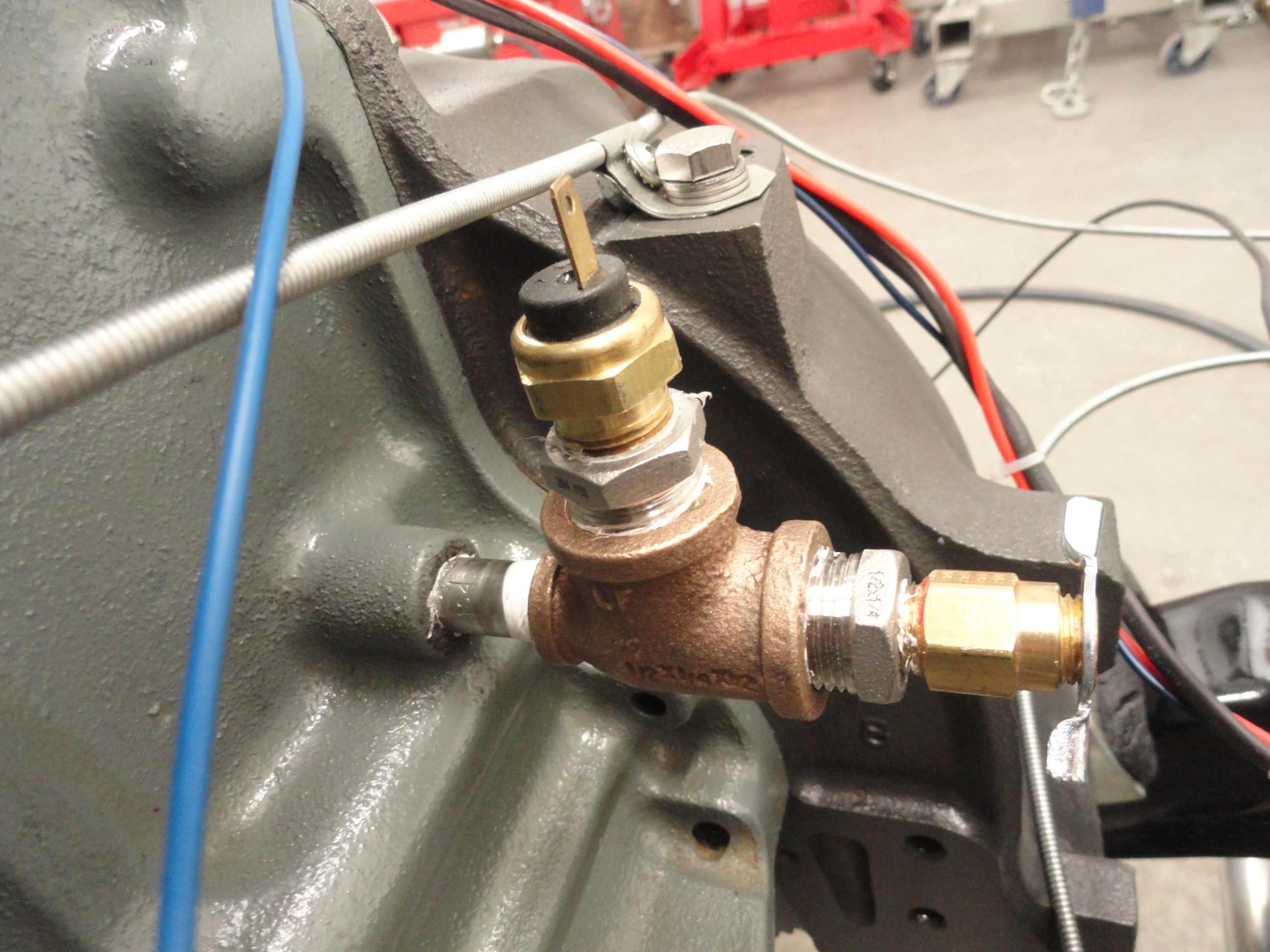
When I say almost perfect, it is because the Thermistor Lug housing is too small to effectively adapt to our vintage vehicles. My plan is to use the 1/4" threaded hole on the Thermostat Housing to attach this Thermistor Sensor. You can still use it for clamping your fuel and vac tubing, but this would just mount under all of that as the first item on that stack closest to the housing. Since we cannot use the Thermistor Lug Housing, we will remove it from the Thermistor taking care not to damage the Thermistor itself. We will then make our own, custom Thermistor Lug Housing to give us the 1/4" diameter hole needed to mount the sensor to our Thermostat Housing. Making this special Lug Housing is not difficult and a thin piece of tin 1" by 1.5" will do the job. I will put a template here once I get the drawing done.


Using a piece of 24 gauge tin (or thereabouts), cut a piece to 1-1/4" by 3/4". Use the drawing and mark it accordingly. Notice the way the original is bent to provide a cavity for the Thermistor to lay in. This will protect the Thermistor. Bend your piece of tin as shown. It doesn't have to look pretty since it will be mostly hidden. We will take protection a step further and use Heat Shrink to keep the leads separated as well as use Heat Shrink on the individual leads. It's very important to insulate the Thermistor from the housing except for the ceramic end itself which will lay down in the tin cavity, then we will use high temp silicon to fill that cavity so the Thermistor doesn't move. Then once the assembly is cured, we will put another piece of Shrink over the entire cavity. Do not put shrink on either of the lug surfaces. Heat transfer cannot be impeded. Once this is bolted down all that is left is to figure out how to route the two sensor wires.

In researching the design of Thermistor circuits, there are many different circuit designs that would work. I am interested in a very solid design that completely eliminates any potential problems. This is why we are using a very stable LM393 IC that has been around for a very long time. This IC is special in that its entire function is to act as a Comparator, comparing the voltage divider's output and giving us a high or low depending on the result. This gives us reliability and consistency since all of the passive elements are fixed (at sampling time). One of the reasons I chose the LM393 is because it has TWO of these comparators and we only need one for the water temperature, and the other Comparator is put to use by incorporating a Supervisory Circuit into the design. Without a supervisor circuit, there is no way to know if one of the Thermistor wires aren't cut since during normal engine operation, there is no way to prove the circuit is working. With this addition, we will always know that the two wires going across the engine, to the Engines Thermostat Housing are in tact and the circuit is working flawlessly. The Supervisory portion has an Amber LED that is mounted to the Enclosure next to the ON/OFF switch acting as a Circuit Fault Warning Light. If that light ever comes on, the end user will know there is most likely a broken wire. A defective circuit would be highly unlikely.
The Schematic above will work beautifully and consistently each and every time. In developing this circuit on an experimental breadboard, then extending wiring to ensure the sensitivity is not lost, all has proven very solid. The Relay type system is THE way to go. The relay isolates the more amp-hungry components as well as acts as an electronic switch. This circuit is adaptable for use with Automotive Electric Fan systems or any other 12VDC application you can think of where a Thermistor sensor is used. This is why the relay makes sense. We can add a higher amperage relay to drive higher amp fan systems.
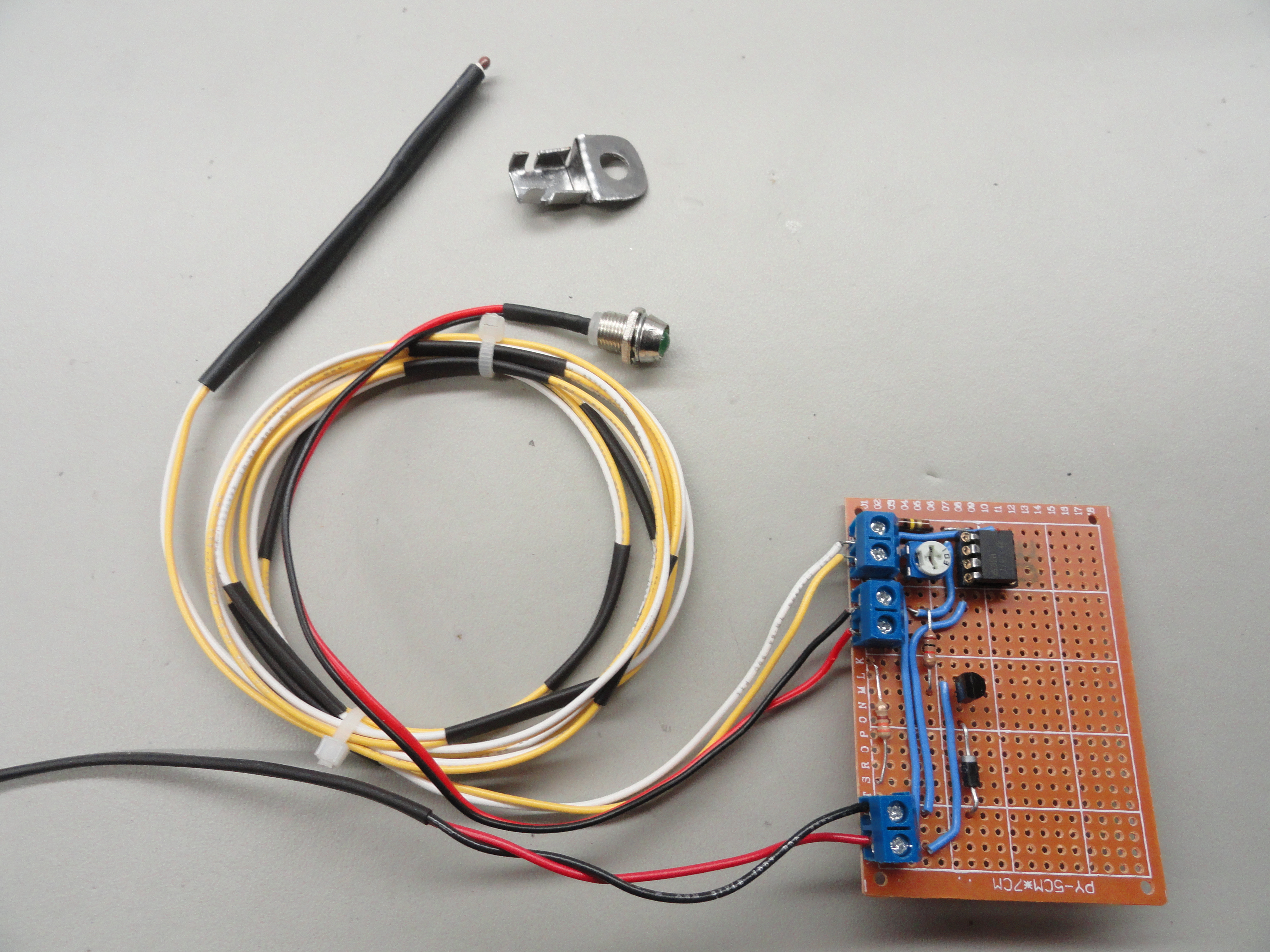
Left is the Protoboard version of the circuit without the Relay and right is the same circuit on the breadboard. The reason I made sure to have plenty of room left over is because I am also putting on this same board a Supervisor circuit that will use the remaining 3 pins of the LM393 and some more components. We will then add a second Comparator for the Low Fuel circuit next.
This is the last circuit addition for the Basic System. This is the only part of our entire System design where any part of the existing measurement system is used. In this case, we need to use the existing Fuel Sending Unit. It just wouldn't be prudent to create another low fuel sender when the one you already have does its job just fine. The idea is to set this circuit up so the end user can adjust exactly where they wish to be warned the fuel is low. If you live 30 miles to the nearest gas station, you might want to adjust it differently than the person with a gas station down the street. We will use a 50K ohm Potentiometer that will be adjustable from empty to half full.
The Fuel Sending unit has a float on the end of an arm that moves up and down with the level of the gasoline in your tank. 30 ohms is a full tank, and 0 ohms is an empty tank. At the same time, 0 volts is an empty tank and 1.6 volts is a full tank. The system was designed so that no sparks can be present at the gas tank, but for their to be an ohm value, voltage must be present. This enables us to create a circuit that will alert us very reliably when the tank is low on fuel. Since this unit measures in millivolts, it is very precise. Even if your sending unit is a 50 or 75 ohm unit, it won't matter. We won't bother adding a relay or anything other than a warning light for this circuit, so this will make it very basic and reliable.

This addition incorporates another Op Amp (LM358) and a three terminal adjustable shunt regulator (TL431) to monitor the very low voltage that is present in the Sending Unit portion of the Stock Fuel Gauge. Once the voltage goes low enough, an LED will alert the driver of a low fuel situation. I wanted this system to be fully adjustable from a half full tank to completely empty. The system incorporates a Potentiometer for that adjustment. It also works with either 6 volt gauges with the standard voltage reducer, or upgraded 12 volt gauges. In addition, the Ohm value of the Sending Unit can be anything below 75 ohms.
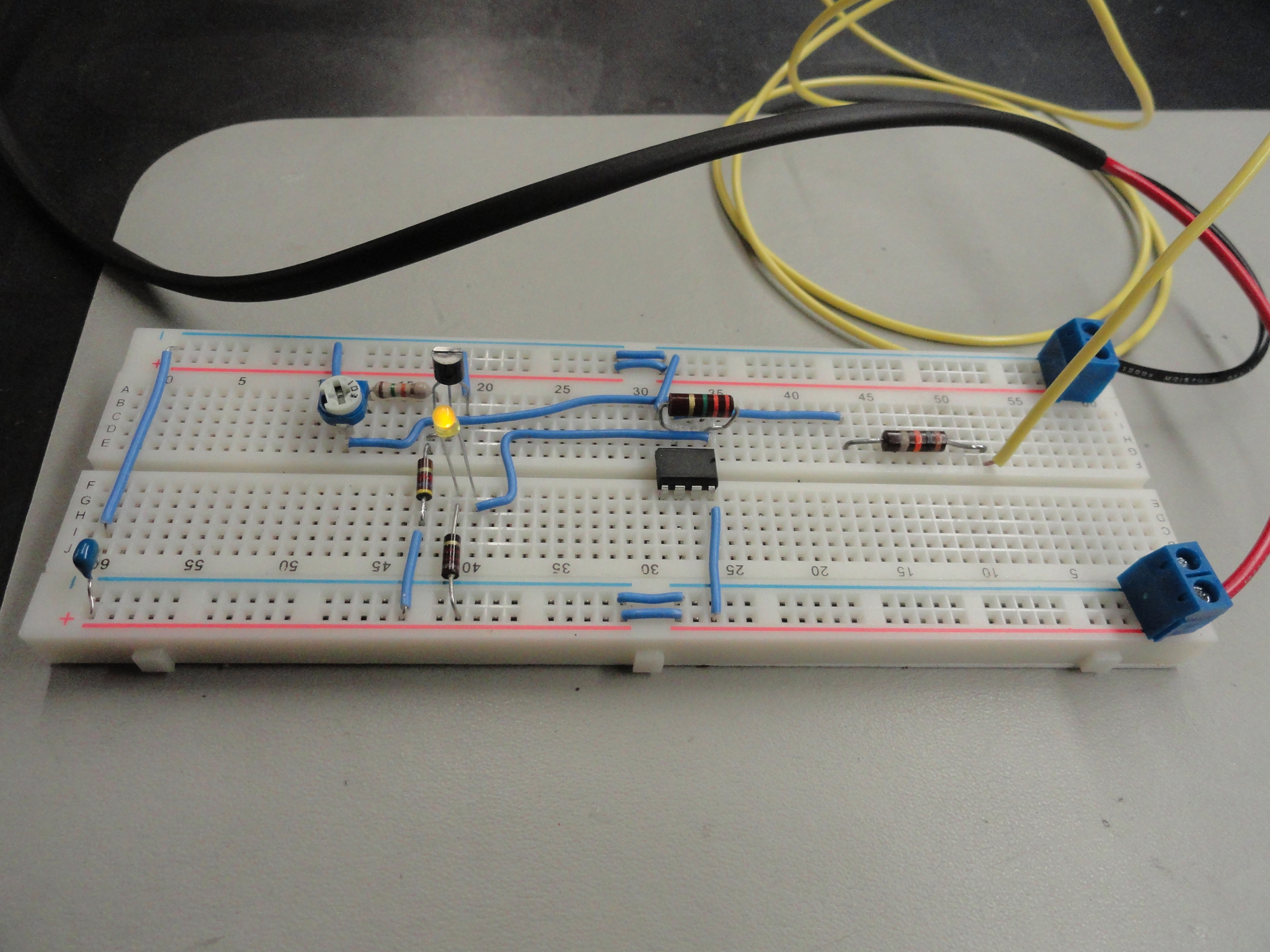

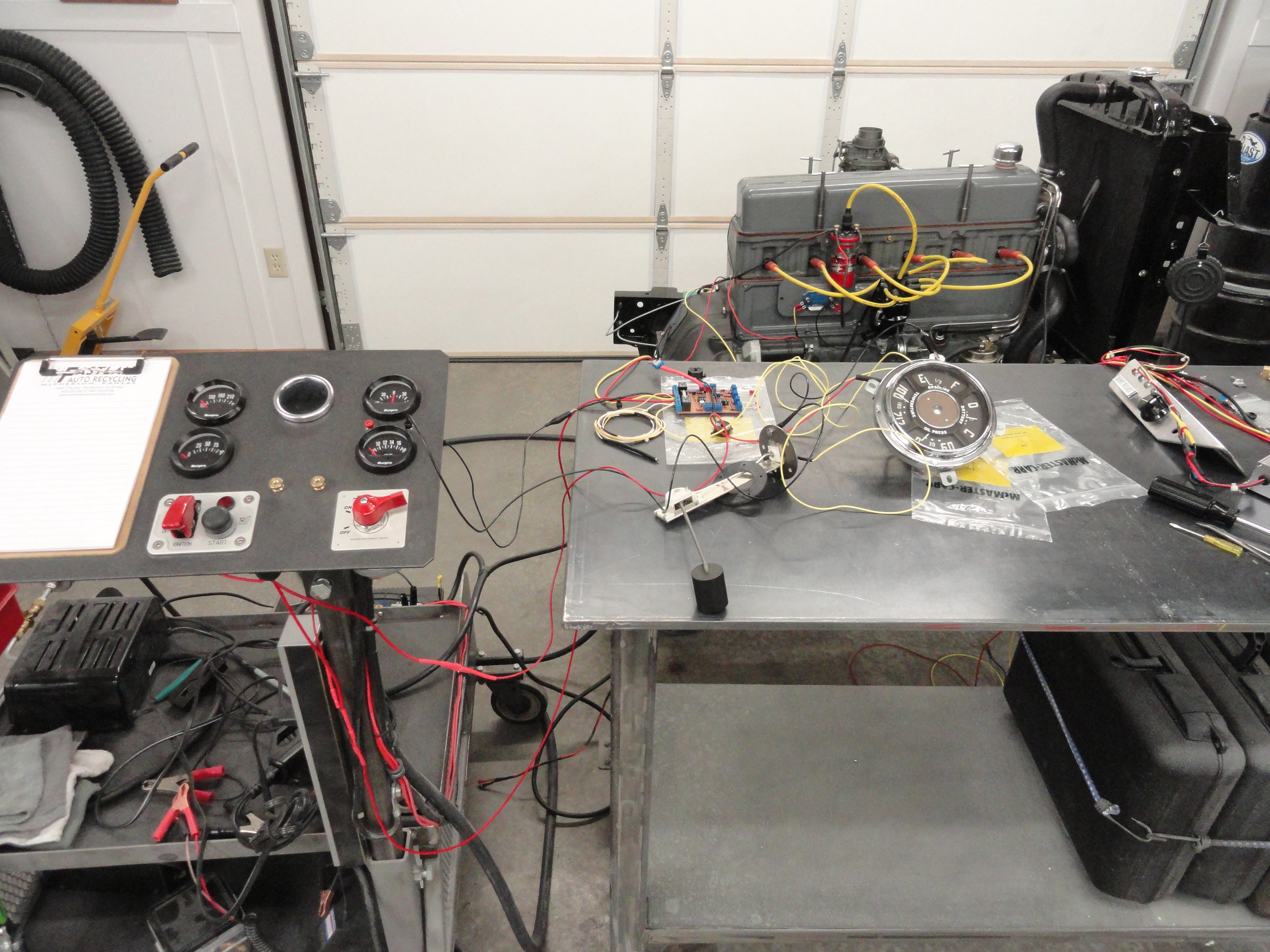
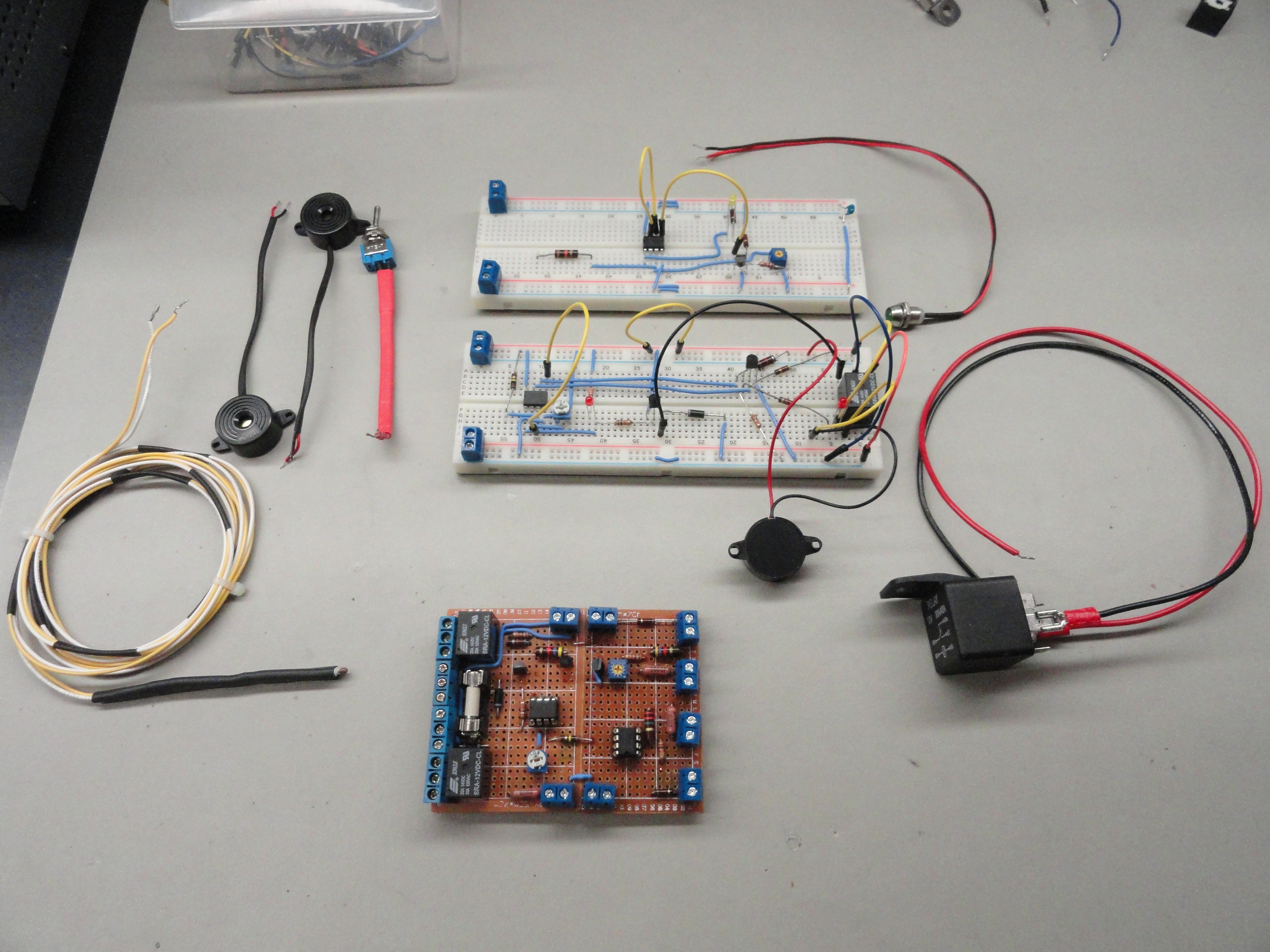
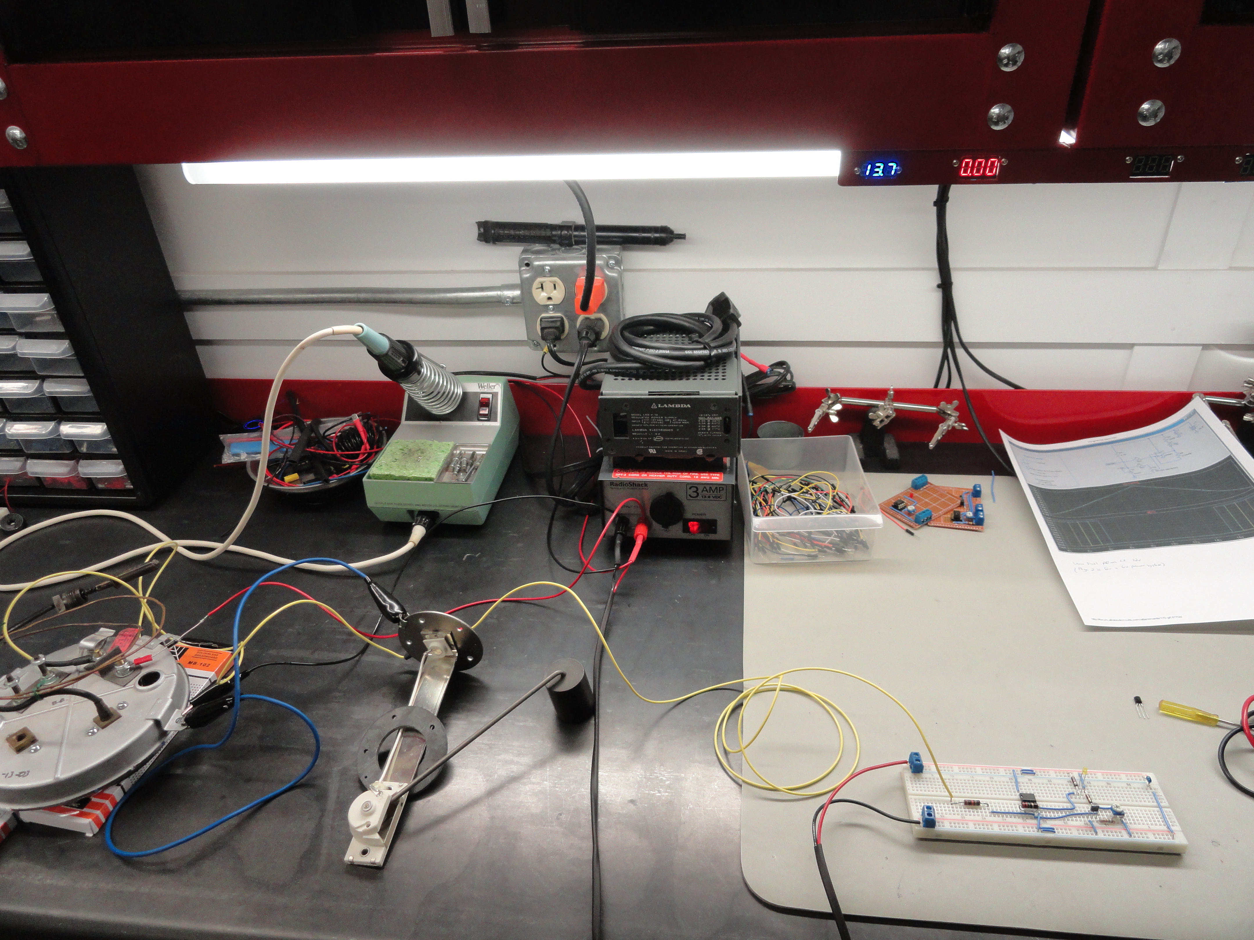
Left is the Protoboard version of the Low Fuel Warning Circuit. Right is the entire Fuel system and how it is hooked up for bench testing.
So we have all of the individual circuits working and tested but individually. Charging System LED, Oil Pressure LED/Audible, Water Temperature LED/Audible and Low Fuel Warning LED. Now all we have to do is put them all on one circuit board and make them work together. The same care and precision we have used to design and test the individual circuits will be observed and nothing will be overlooked. This is real progress!
These new circuits will incorporate quite nicely into the system as a whole and are relatively inexpensive to make. The time to put the component parts together and test the circuit is about a day. Assembly of the entire warning system is longer of course, requiring drilling various holes in the enclosure and wiring everything. This solution is very possibly the best way to go since availability of the ready made boards are so sporadic. There are other advantages, for example none of the ready made boards come with an automotive grade Thermistor and have to be replaced. Parts are not the best quality and things like DIP sockets are non-existent. I am doing this for my friends, so it's really a no-brainer!
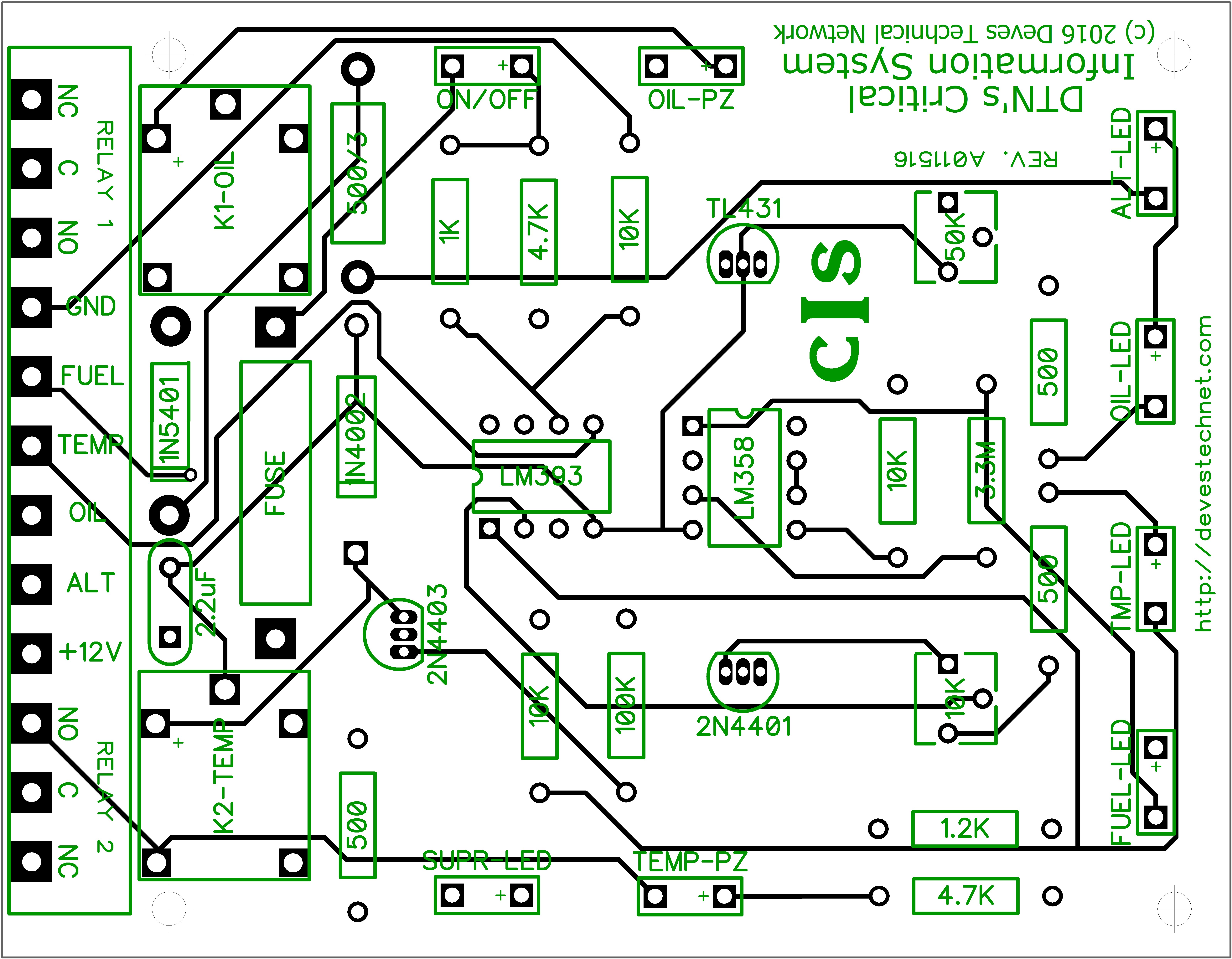
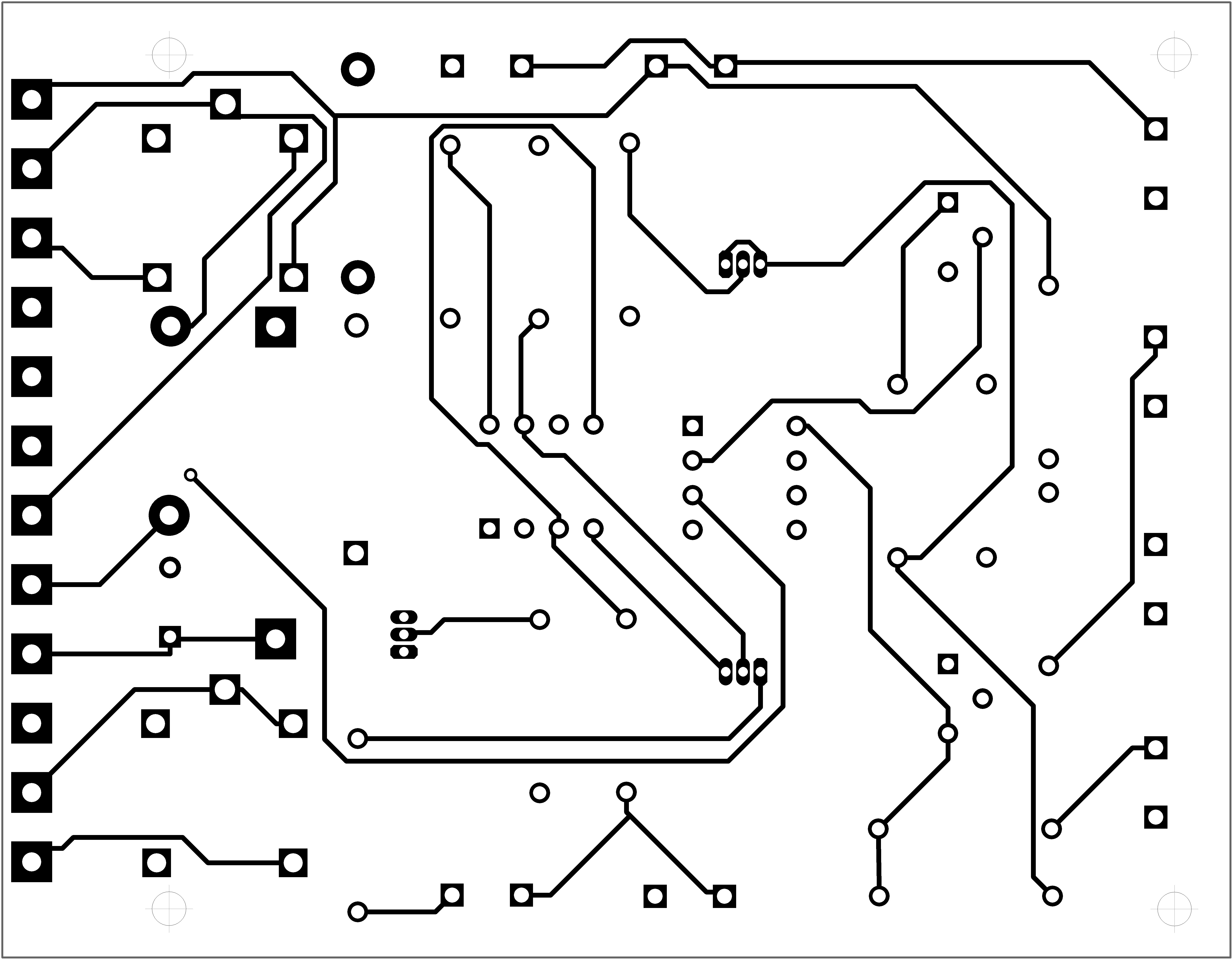
This puts us at about January of 2016 and there is still much to do. From a prototype design, we need to put this circuit into production and have suitable circuit boards made. I am still contemplating if I should solder all of the components on myself or have the board manufacturer do it. I will put pricing and availability here so you can learn something too! Meanwhile there is lots to do in melding these circuits together and learning a new software program that efficiently turns a schematic diagram into a circuit board design.
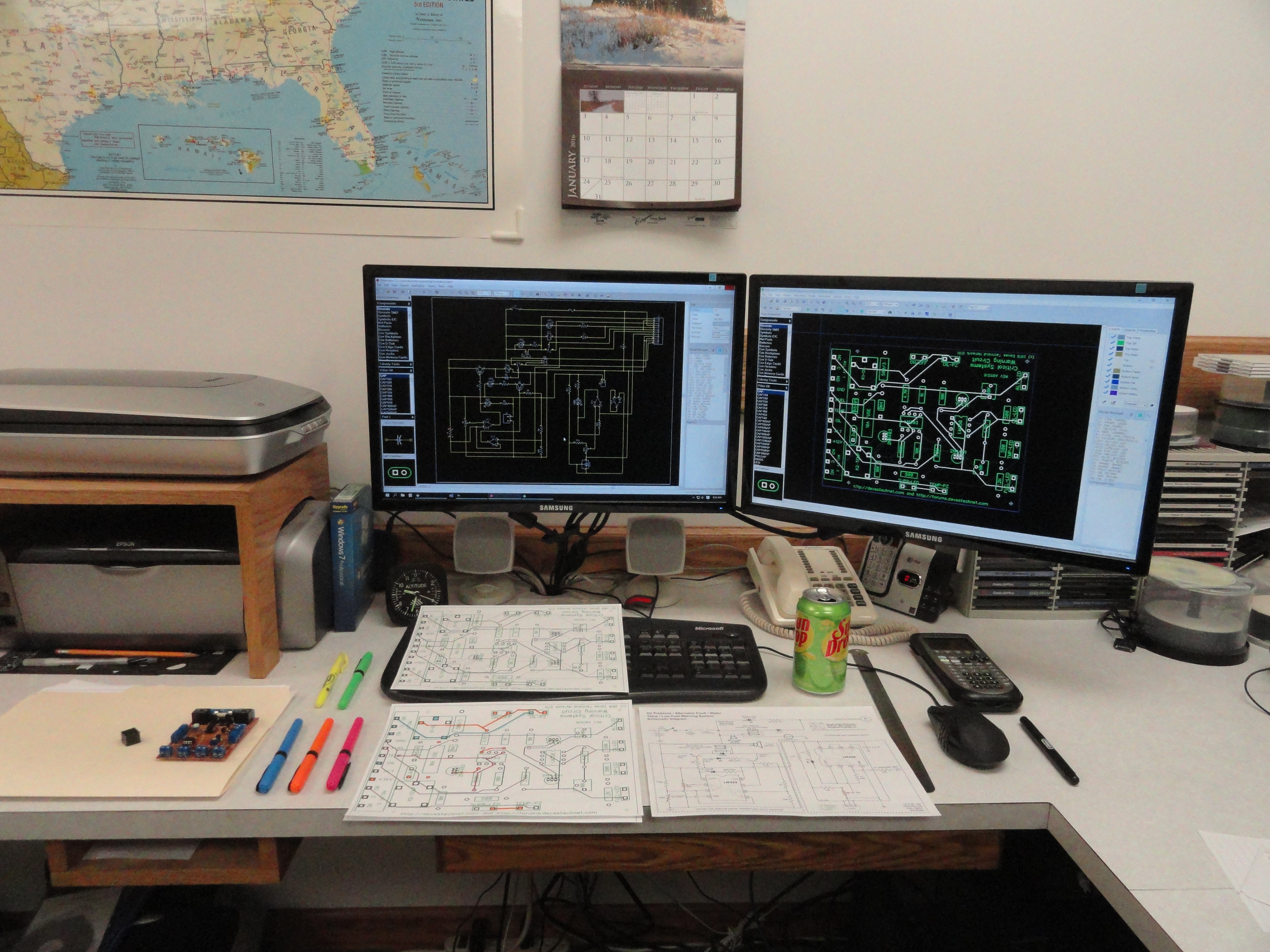
Enter a program called DipTrace. Back in the late 70's when we were making upgrades for the original Atari computers, we had to use nasty chemicals and trace material for this. Now, you just spend a week or so learning how to use the software, and off you go! This program is really the ticket for this application. It starts you off having you enter your entire schematic diagram into its Schematic Applet. I learned that this is not a proper schematic, rather an electrical representation of what we need the end result to look like. The difference is that an LED (or any component) that is not on the circuit board will just be two pads labeled "LED2" for example.
Once the schematic is put in and everything is right, time to "Convert to PCB" which throws all the parts out there for you to move around into a coherent circuit board. Its quite fun really figuring out all the nuances. I thought I was done many times and had to go back and fix the schematic and start all over again. It's a learning process. The program is free for 300 pin applications or less. Since this project has a little more than a hundred, it was free for this project. In the end, from start to finish learning this program to ordering the boards, it took about 2 weeks. The program has an agreement with Bay City Circuits and two of these boards with shipping cost me $65.00 with a 10 day delivery time. I do not want more than that for the first order because I am not sure enough of my work to purchase them in bulk yet. When I do, I am sure I can get the cost below $25 a board.
Remember, after all of this journey, we are not using anyone else's circuit boards for any part of the design. This system is all on one board and incorporates all of the advertised features without relying on anyone else's schedule or parts availability to get this done. That is a very big deal! Here are a few shots of the PCB Design just after I placed the order.
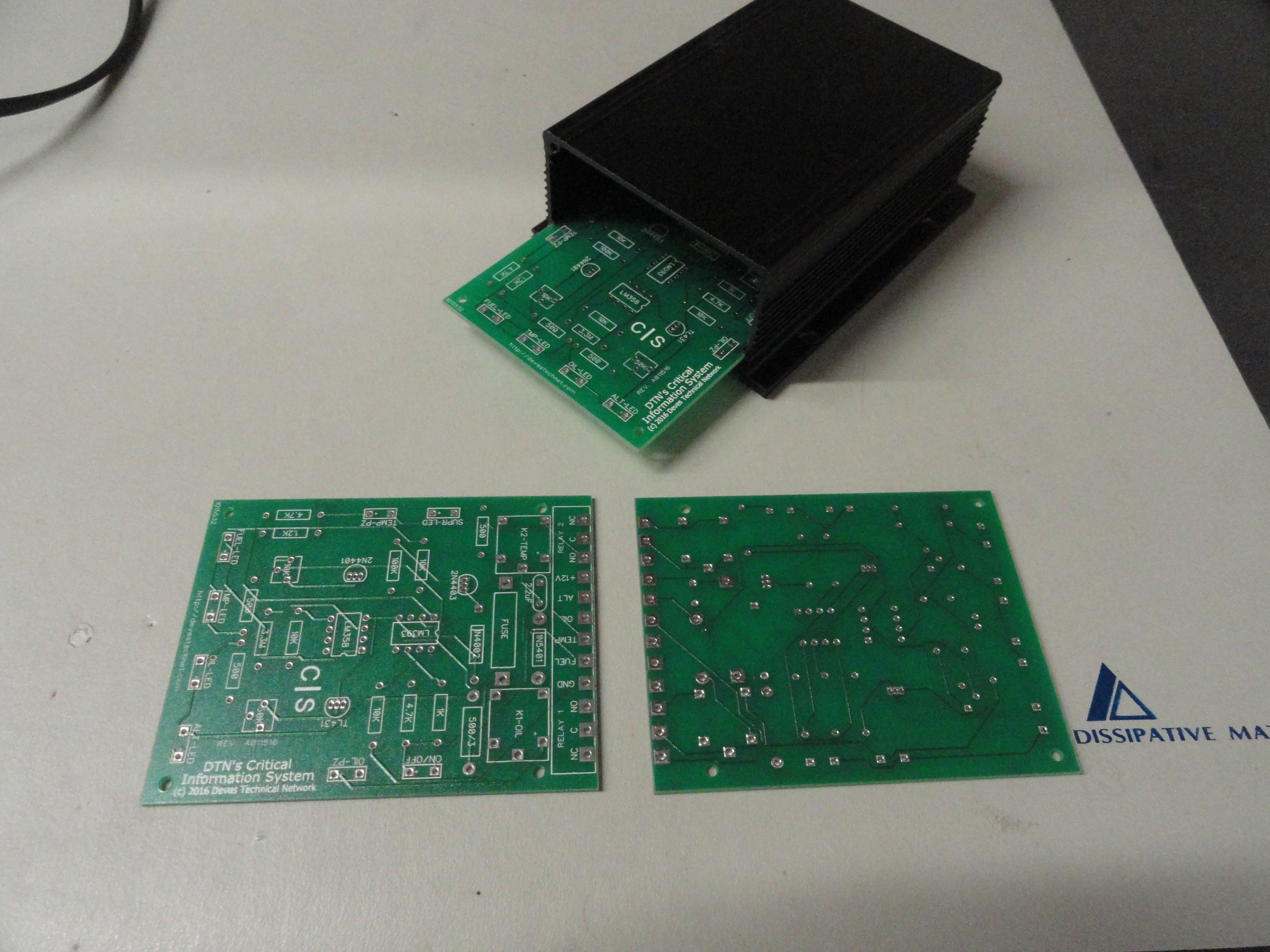
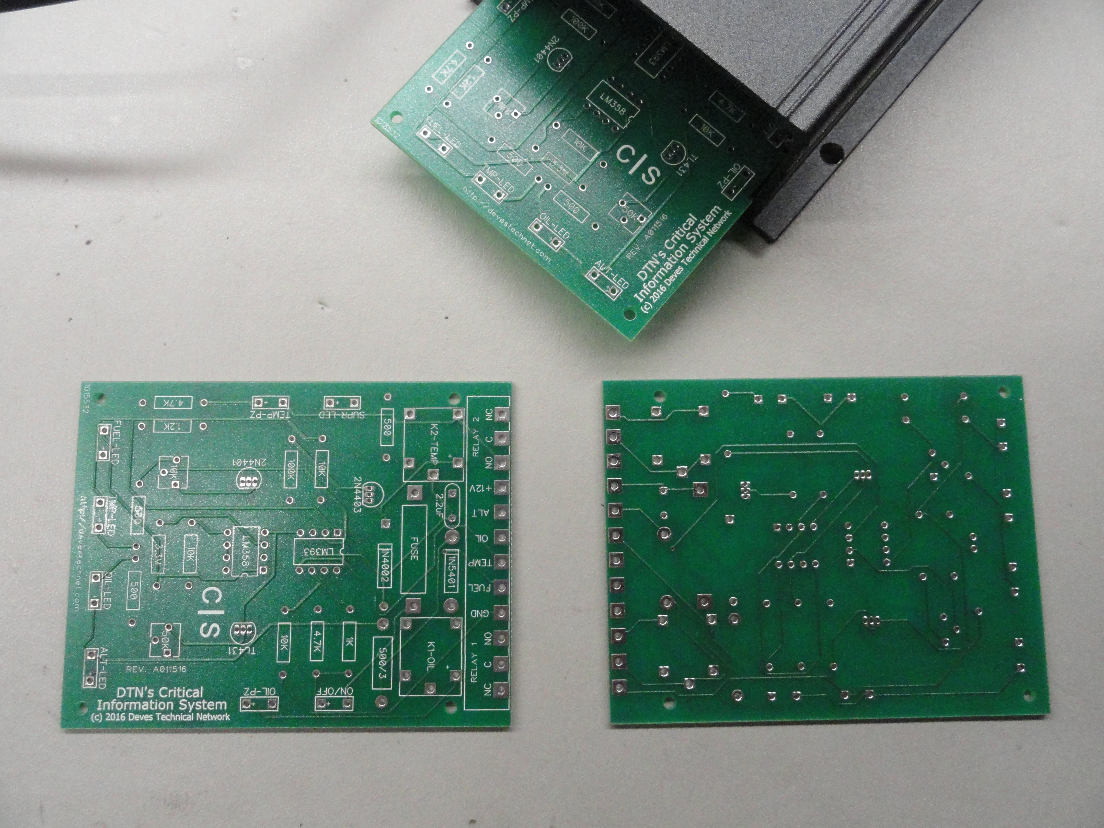
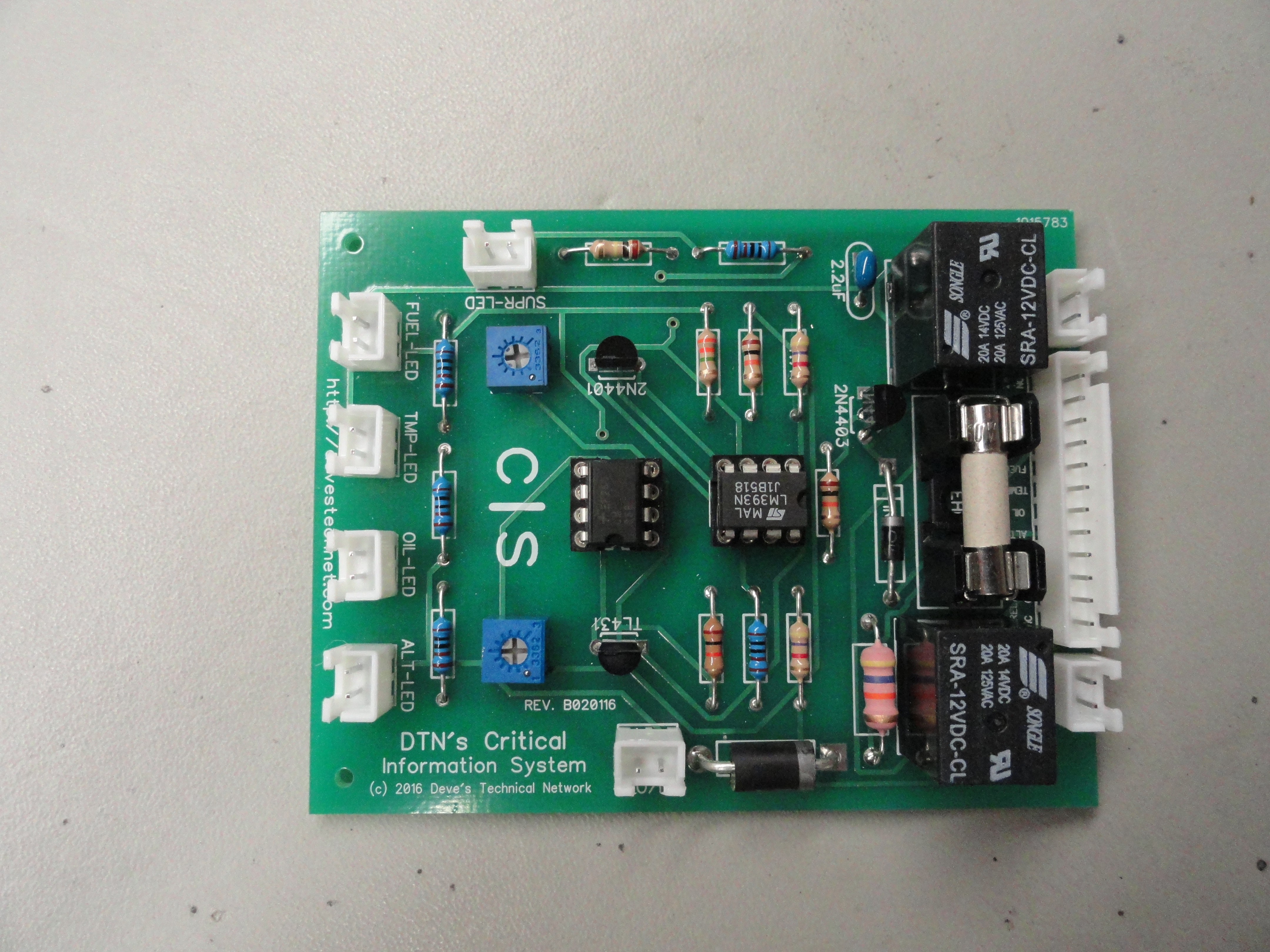
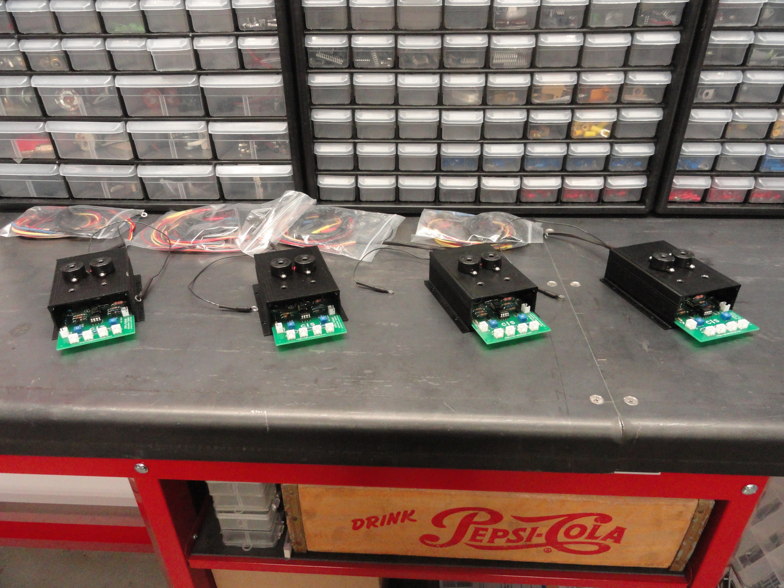
The completed boards were delivered via Priority USPS and instead of the two that I ordered, I received three! I was astonished by the quality and how perfect they looked. Everything that was represented on the computer screen and printed out on an inkjet printer was exactly the same only with much higher resolution. I have absolutely NO problems with the boards I received from Bay Area Circuits. These pictures were taken after I got them. The size is perfect for our enclosure and everything is properly marked. Very impressive! The cost for the two boards I ordered was 64.50 including shipping. So a little over $30 each. I am sure I could get them made in China for much less, but that is not the way I am leaning right now. It is wonderful we have this service in the US and I very much want to support our industry.
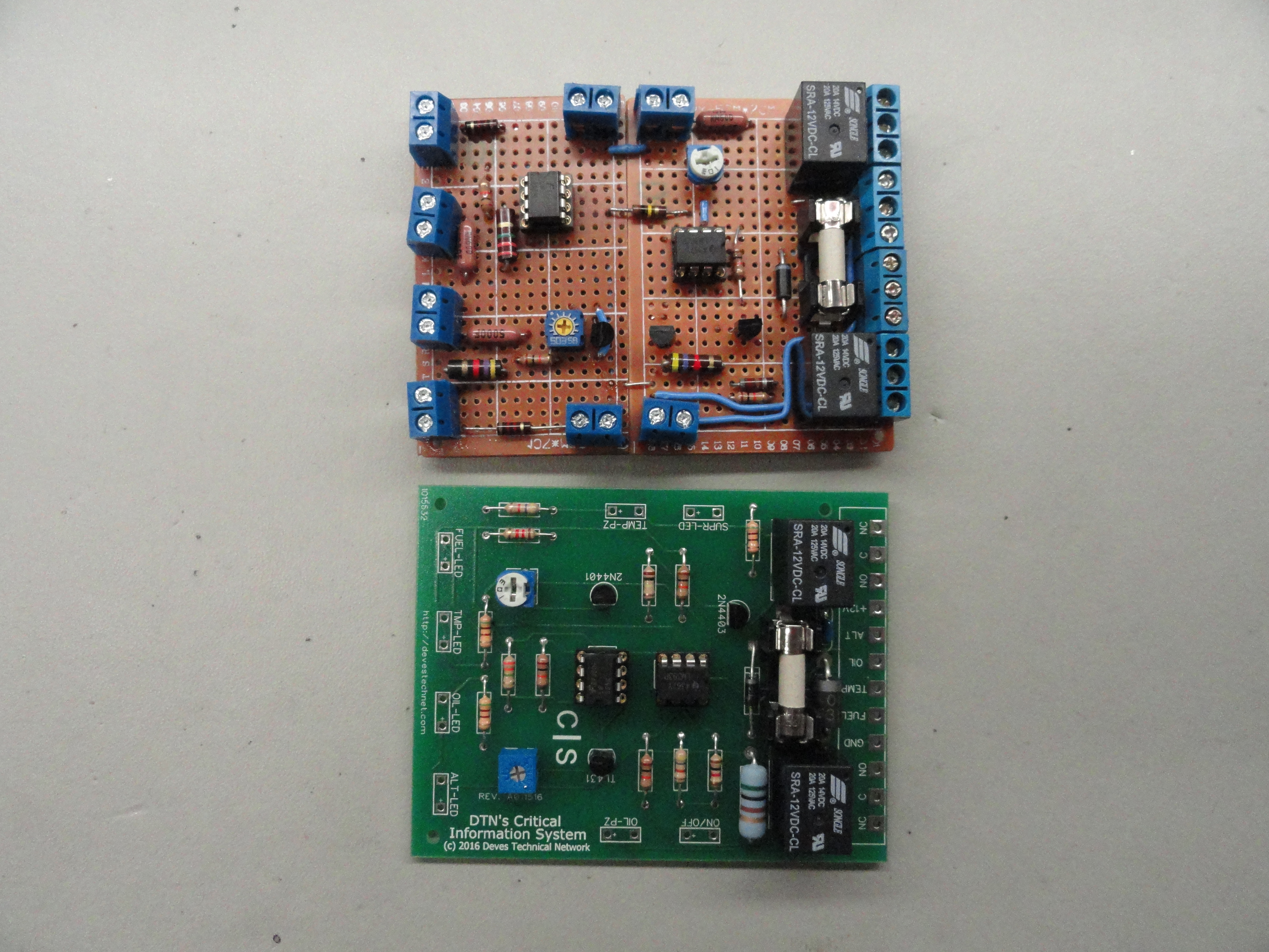
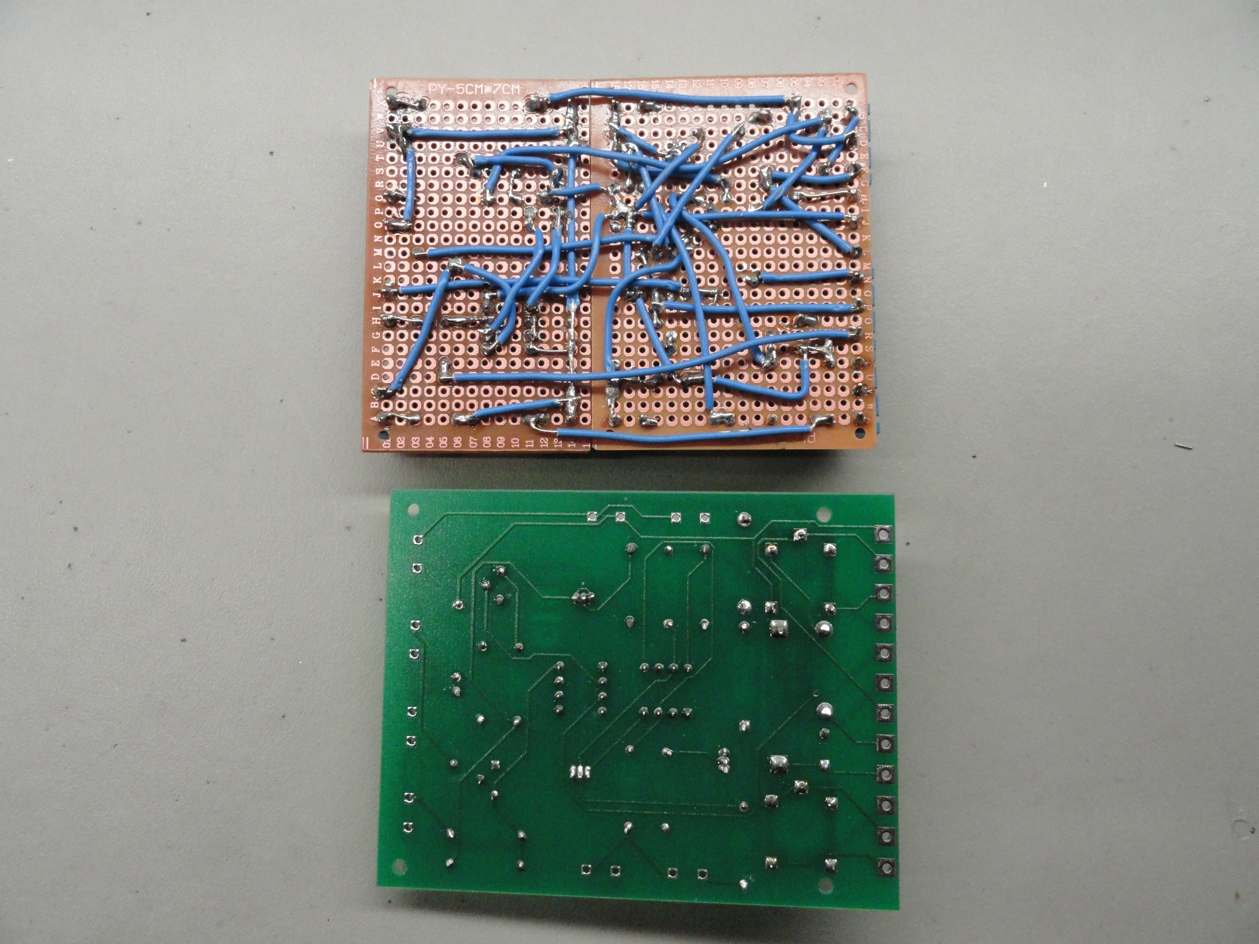
Here is what the prototype looks like beside the actual manufactured product. This is just part of the process to make one the hard way and test it before having the good ones made. I am glad I do not have to do that over again! But the prototype works MUCH better than it looks!
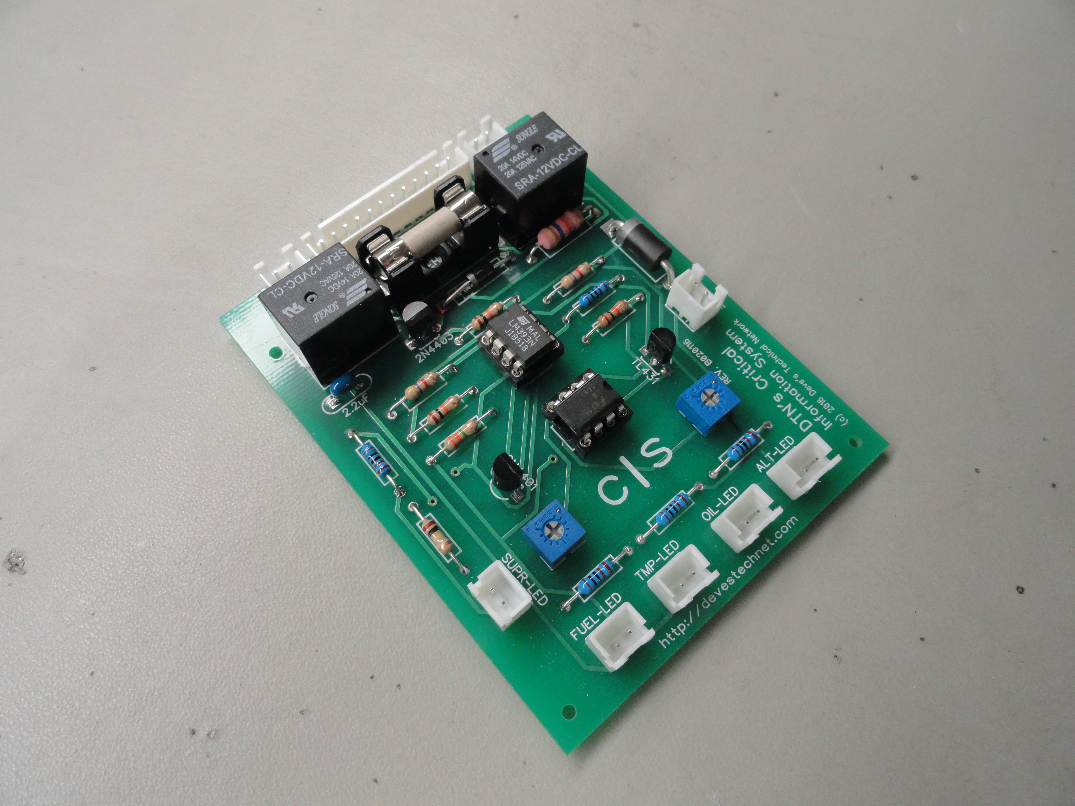
Here is the new board fully populated. All of the rest of the connections on the board are to components that are not on the board. Since this picture was taken, we opted for a 12 pin PCB mini-connector and 8 2 pin PCB mini-connectors to connect all the wiring. This is how aircraft and automobiles are wired to prevent wire breakage from excessive vibration. Now with the proper connectors in place, this system is complete and ready for action. Many hours of testing, examining each parameter and then going back to the drawing board was done before coming up with this very solid system. We sure hope you like it!

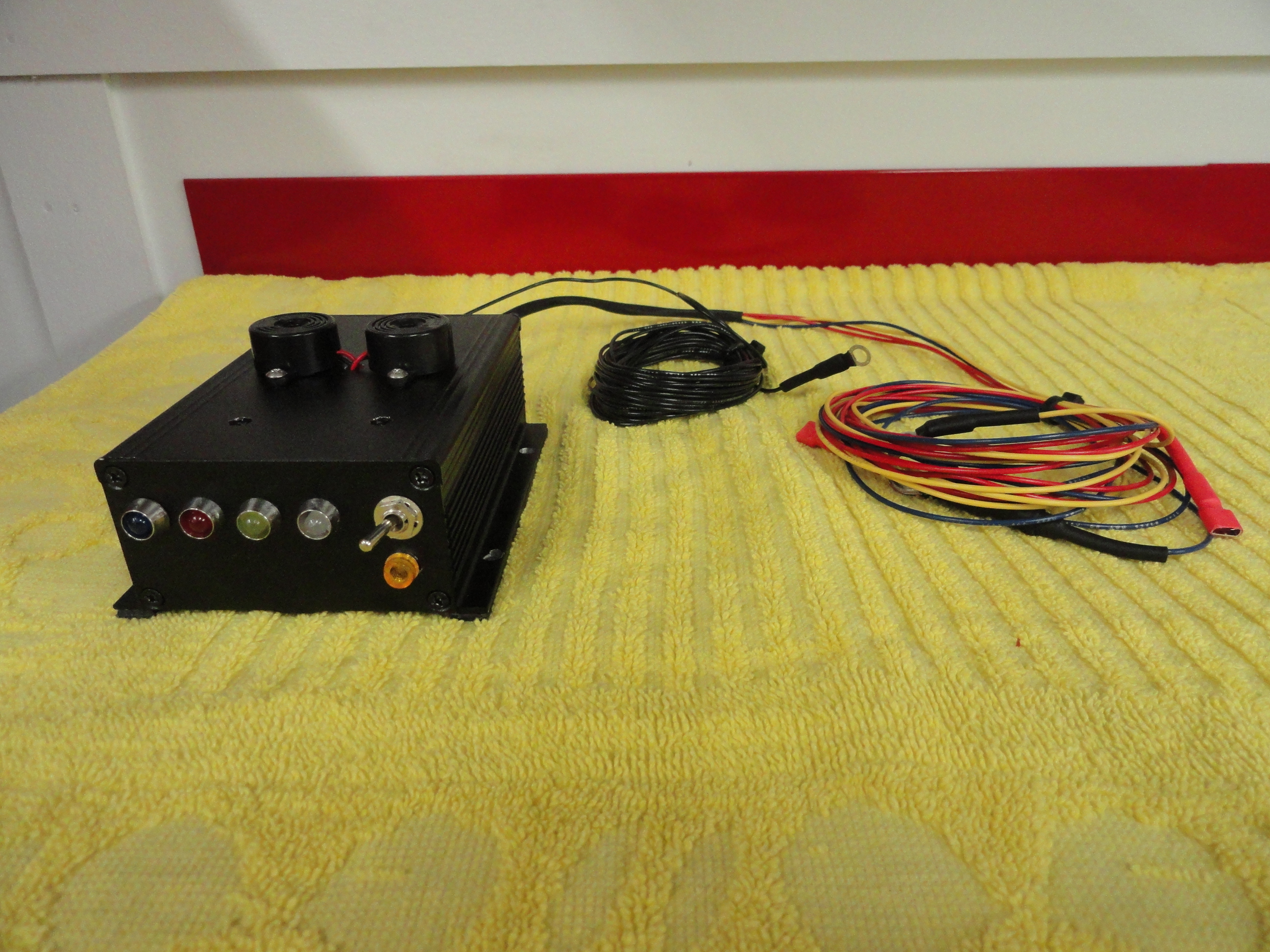
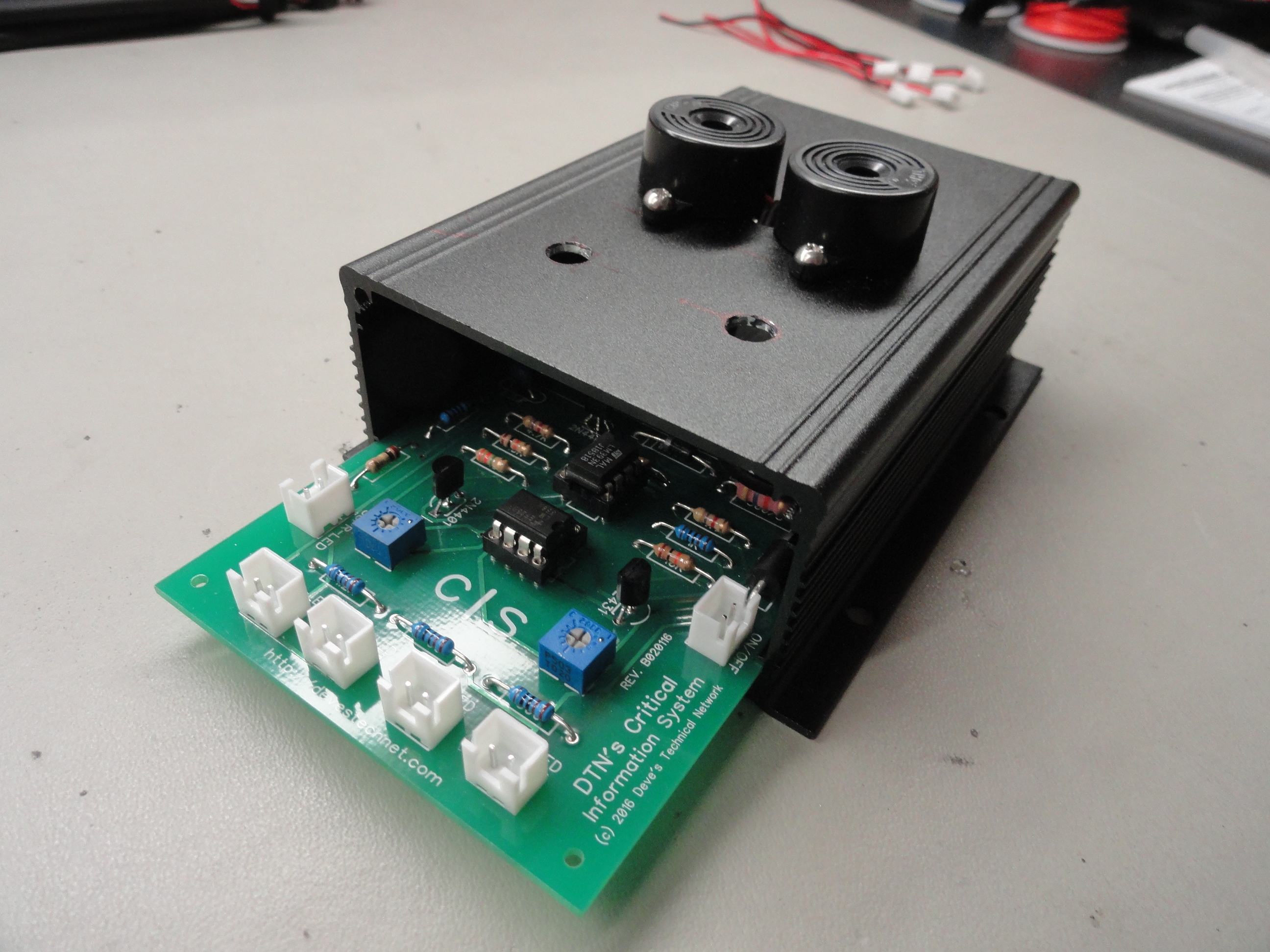
Here is the completed Warning System. The Water Temperature circuit changed a few things that I had to go back and correct in the article. Designing the circuit from scratch removed the requirement for an 8 pin relay and gave us the advantage of going to a set of mini 20 amp PCB Relays. This allowed me to use a small box for our system which makes it easier to hide under the dash. The switch completely kills the power to the box and inside of the box is a 10 amp fuse mainly to protect our circuit from any surges by an outside source. The Piezo Buzzers are on the outside to ensure they are loud enough to the driver. The driver should hear the alarm and pull over immediately and shut off the ignition. This resets the system. In any other case, the driver can reach down and flip the switch if it becomes irritating.
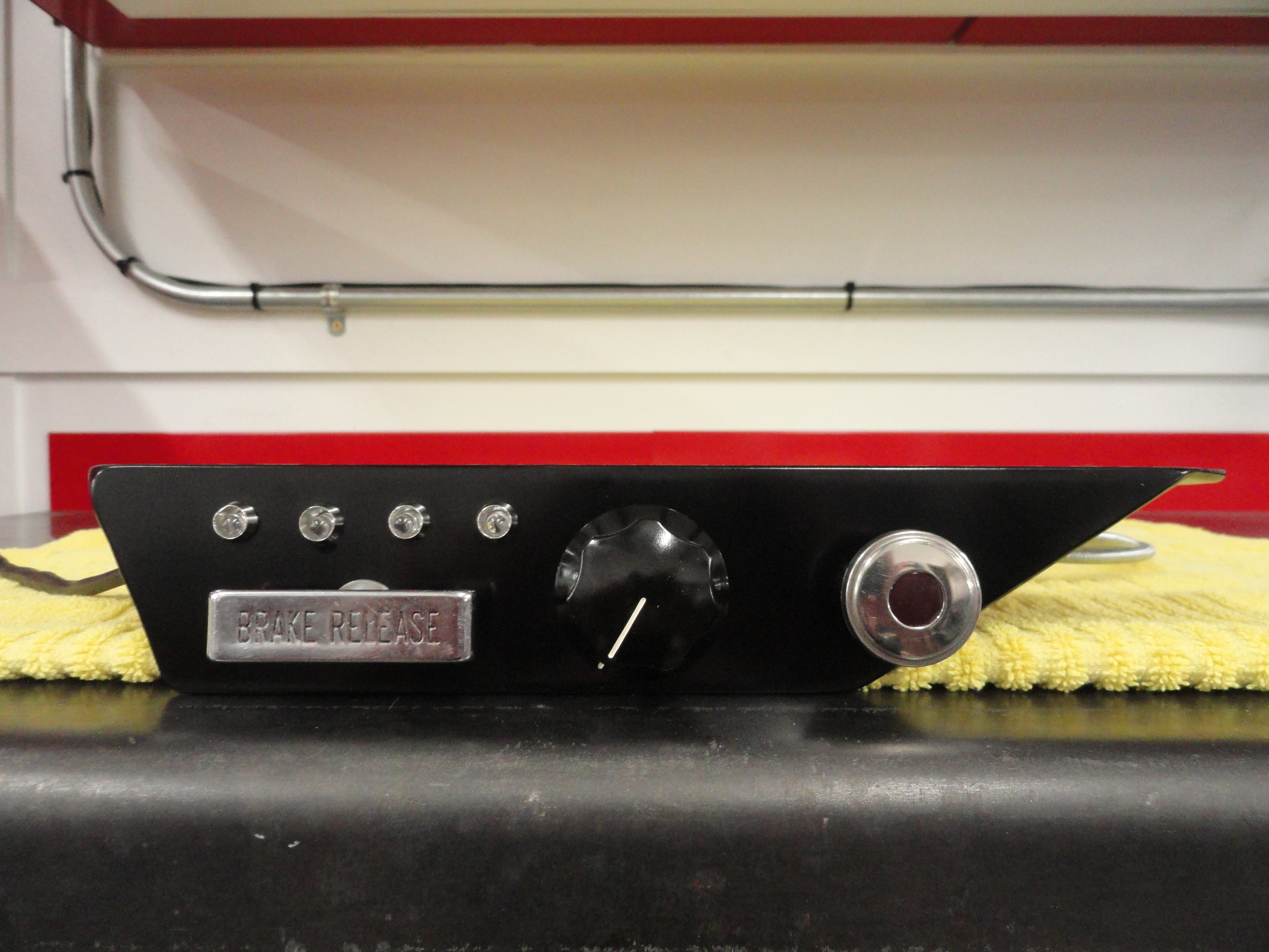
Here are shots of the Indicator system. The idea is to give those who want a lighting system that choice in a tasteful bracket that uses the unused left side of the dash. It is also a really good time to change over to a DC Motor Controller and Linear Potentiometer for your Heater! If you do not like the looks of this dash piece, you can opt for just the warning box with the Audible Alarm only and lights mounted directly on the box. Making two separate types was necessary to accommodate those who just want to hear an alarm when a critical system goes bad, and also those who want to see visual indications as well. If you have any suggestions on what you would like to see changed, please let us know.
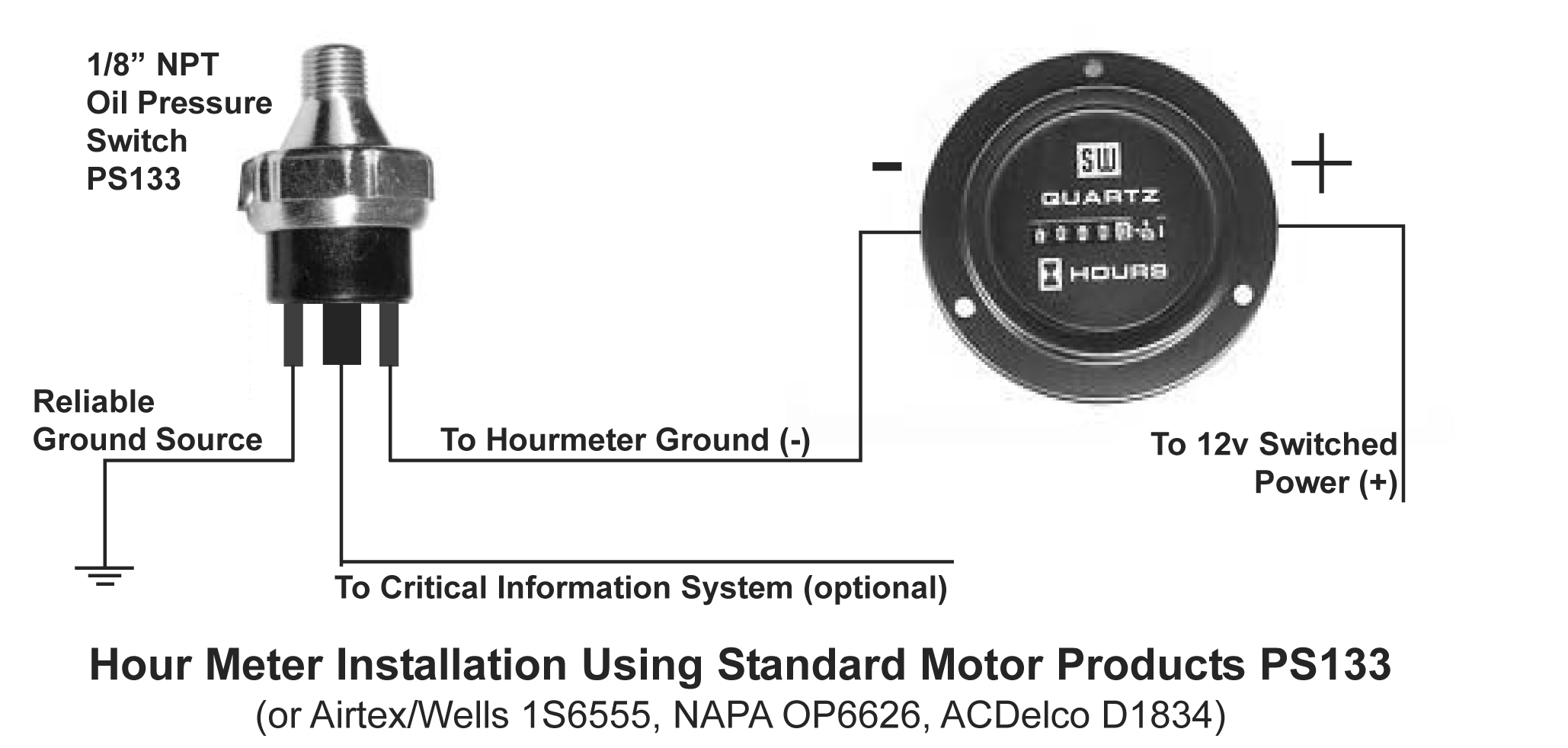
I put this material here because someone wanted an Hour Meter driven from the Oil Pressure Switch and since we are using one for the above system, maybe, JUST MAYBE there is a way to incorporate this function and still use just one Oil Pressure Sensor. Enter the Standard Motor Products PS133 Oil Pressure Sensor/Switch. The sensor has three terminals. The way they are situated on the switch, two oppose each other and one is sitting in between the two sideways. To install this switch properly, follow the Schematic provided. The two that oppose each other are the ones used for the Hour Meter. It does not matter which of the two go to ground and which one goes to the Hour Meter. Explanation: The way this switch works is, Oil Pressure pushes a plunger away from the oil source. The two contacts opposing each other connect together when there is good oil pressure, and disconnect from each other when oil pressure is lost. The center contact (the one in between the two opposing contacts) is grounded to engine/chassis ground before oil pressure is applied. Once Oil Pressure is applied, that contact LOSES ground.
So as you can see, we can use this switch for both purposes. The nice part about using the Oil Pressure Switch for the Hour Meter is it only counts the hours the Engine is actually running. If you are not in to Hour Meters, there are other uses for a signal that signifies "Engine Running". It's just a matter of using your imagination! We are doing a similar thing with the Critical Information System except we needed the Alternators Warning System attributes to keep the Alarm silent at Ignition ON.
We are constantly developing more fun stuff for your engine. The Kits that are available now are Regular and Deluxe PCV Upgrade Kits, Spin-on Oil Filter Adapter Kits, our popular HEI conversion kit and our Critical Information System. Check out all of our offerings at Farm-it-Out!