


Deve's Technical Network
1947-1955 1st Chevy Trucks
216/235/261 Engine Solutions & More
This is yet another GIANT breakthrough for us Vintage Vehicle Enthusiasts! This system monitors your most critical systems on your vintage vehicle in a similar way your modern vehicles take for granted. This system is a proper Redundant backup system for your gauges providing you with bright LED lights that alert you of a catastrophic failure as well as provide you with an Audible Alarm for the most important systems. Rather than scanning your gauges and hoping you catch the failure in time, let the vehicle tell YOU when it needs urgent attention!
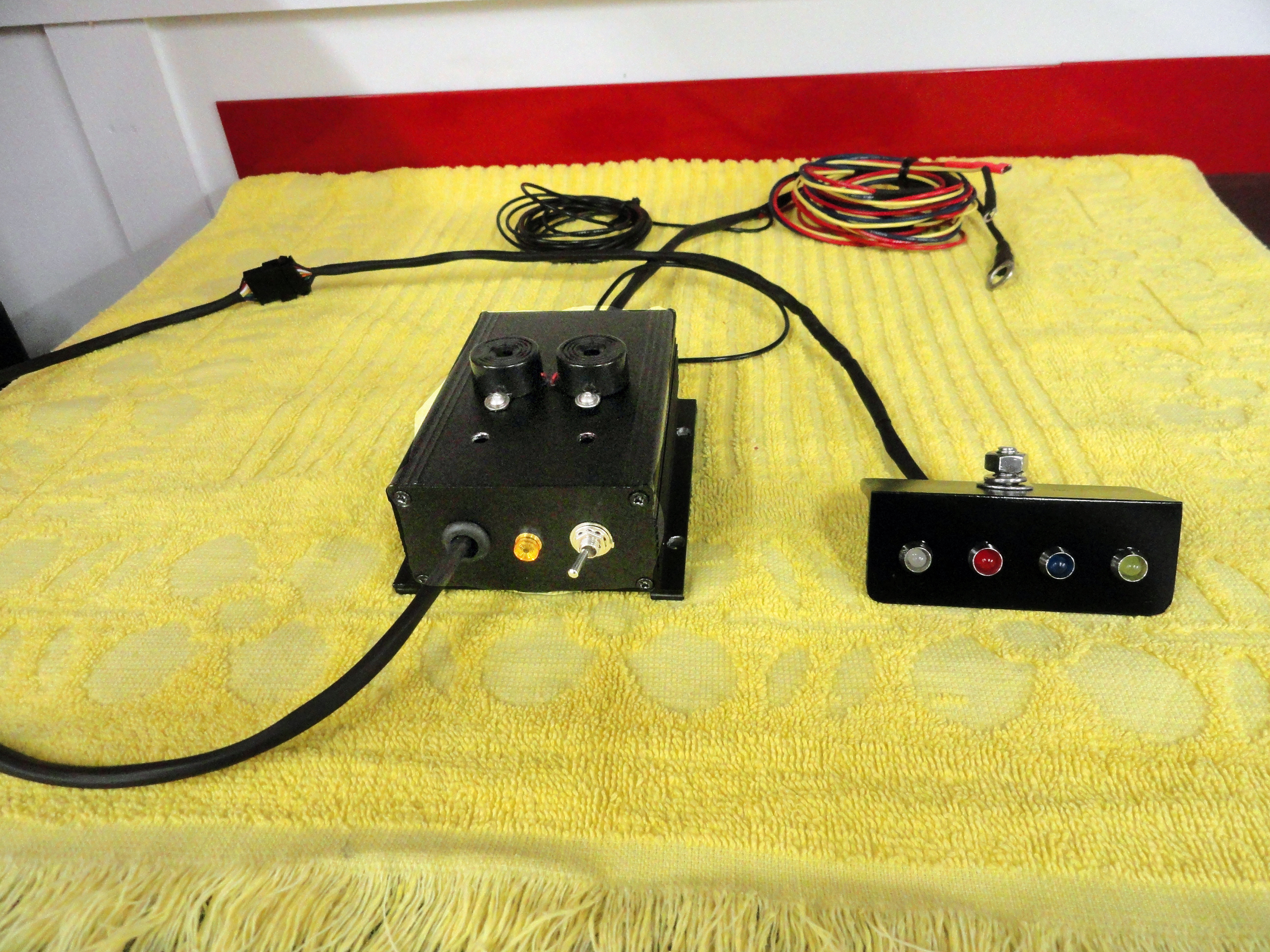
Start by identifying all of the parts above. In some vehicles that have newer wiring, the Alternator warning light wire may already be run into the cabin. We did not take that for granted. This installation will require routing of 3 wires from the Black Box into the engine compartment. Find a suitable route for your vehicle to get them through the firewall. Read to the finish of this article before making any changes to your vehicle!
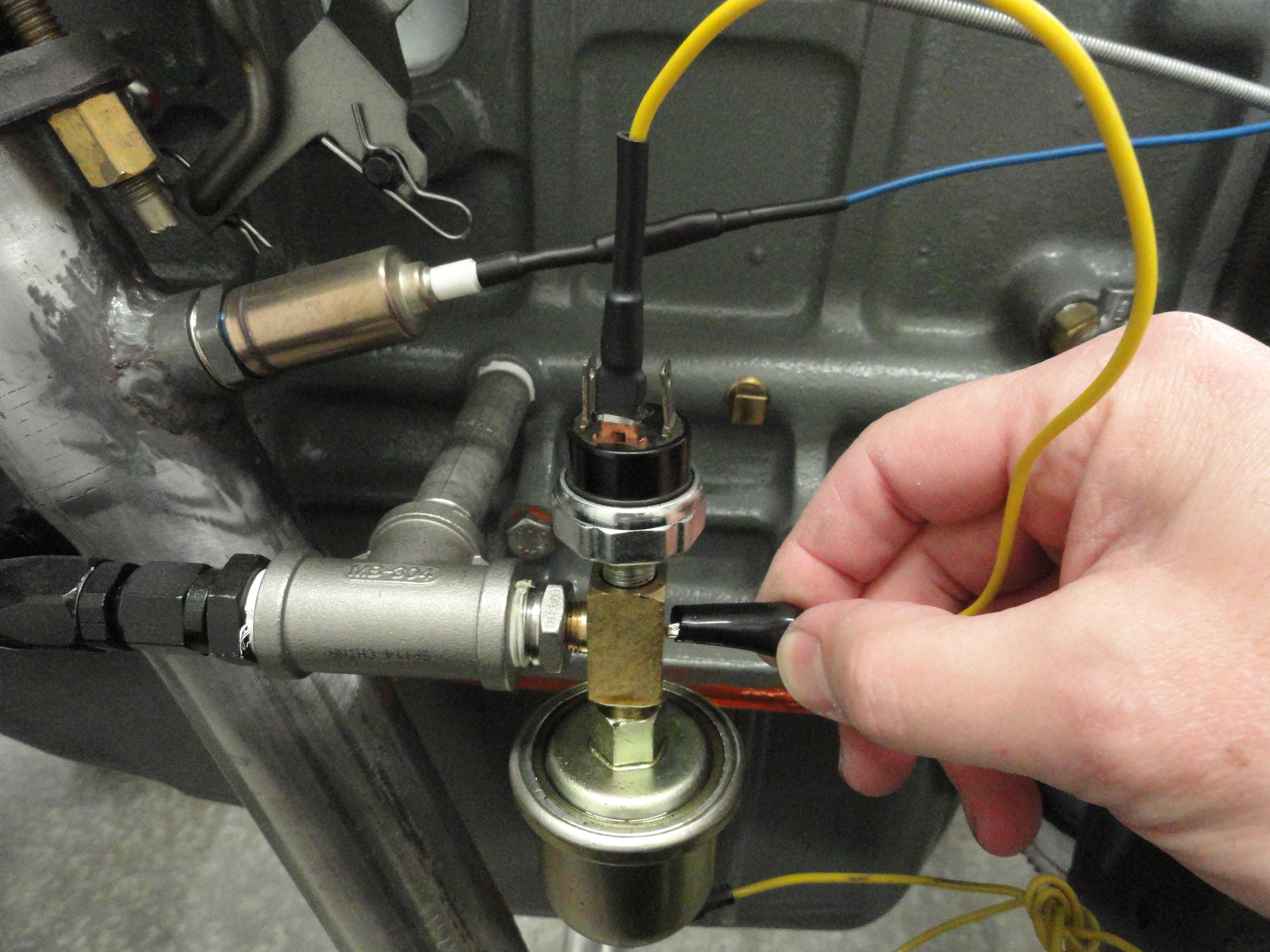
Install the Tee Connector to your engine's oil pressure system. On the drivers side of a 6 cylinder engine closest to the firewall is where you should find the small copper tube that comes from your Oil Pressure Gauge and connects to your engine. Disconnect that line and install the included Tee Connector into the engine block. These fittings should all be 1/8" NPT so they should fit together perfectly. Use Teflon Tape or a good high temp sealer on the threads. Orient the Tee so that there is sufficient room for re-connection of your Gauge and the included Sensor. Installation of the Tee and the Sensor with the stock gauge connection will seal the system. Later we will attach a wire to the end of the new Sensor. Tighten the Tee but be careful to not over-tighten!
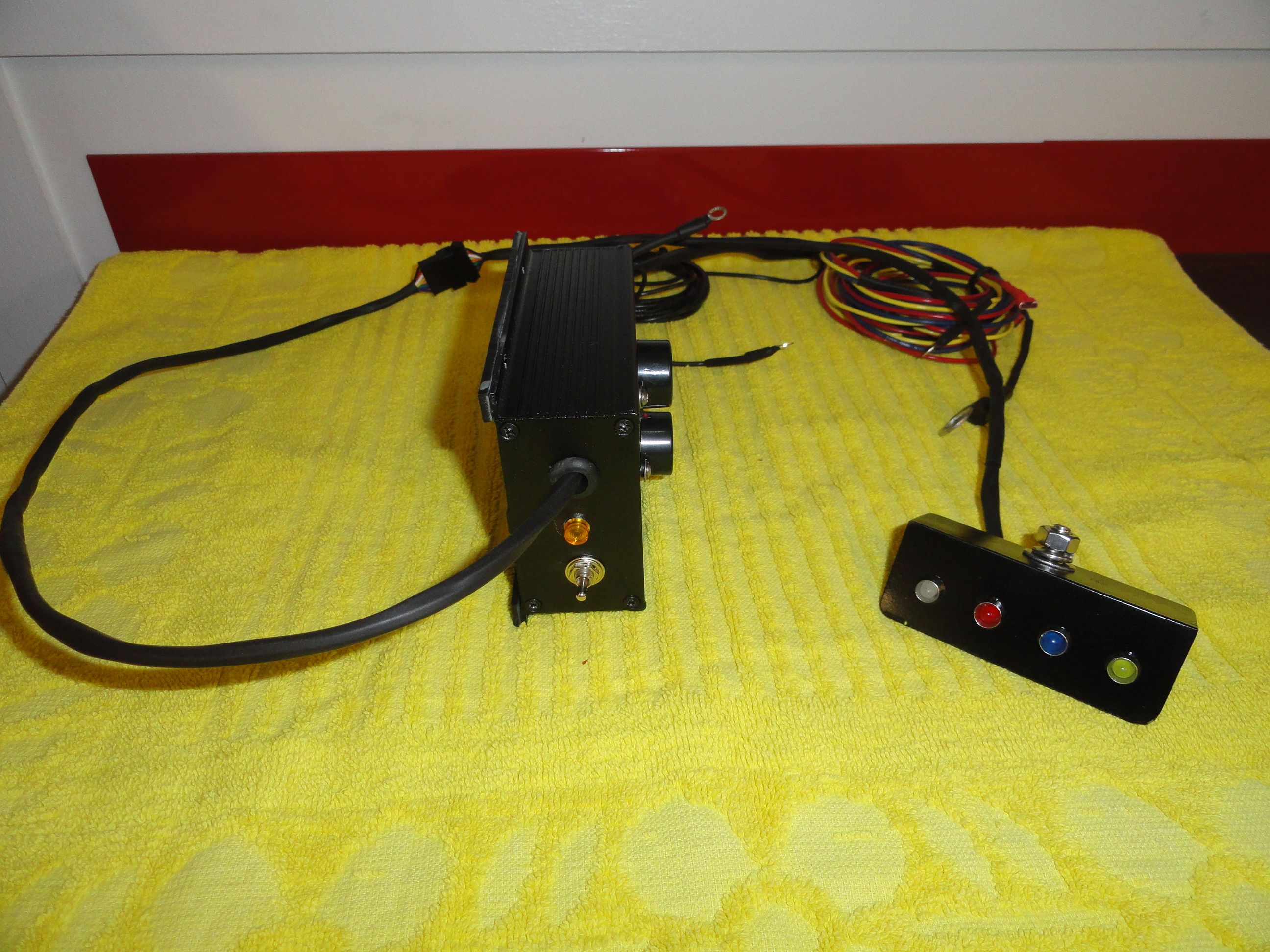
Locate a good place to install the Black Box. This is owner preference, however, if the drivers side kick panel (up high) is available, that is a good choice. Reason being, there is a switch on the Box that cuts power to the entire system. You may want to have ready access to this switch in case your system activates and you want to shut it off quickly. (Do not forget to turn it back on once the engine problem has been fixed). The Black Box comes with Four #8 Stainless Sheet Metal Screws for attachment. The Piezo Buzzers used for the Audible portion of the warning system are attached to the outside of the box. These are very delicate so install your unit so that you won't be kicking the box or rubbing against something. Install so that the panel with the switch and caution LED are toward you and the wire bundle is facing toward the engine.
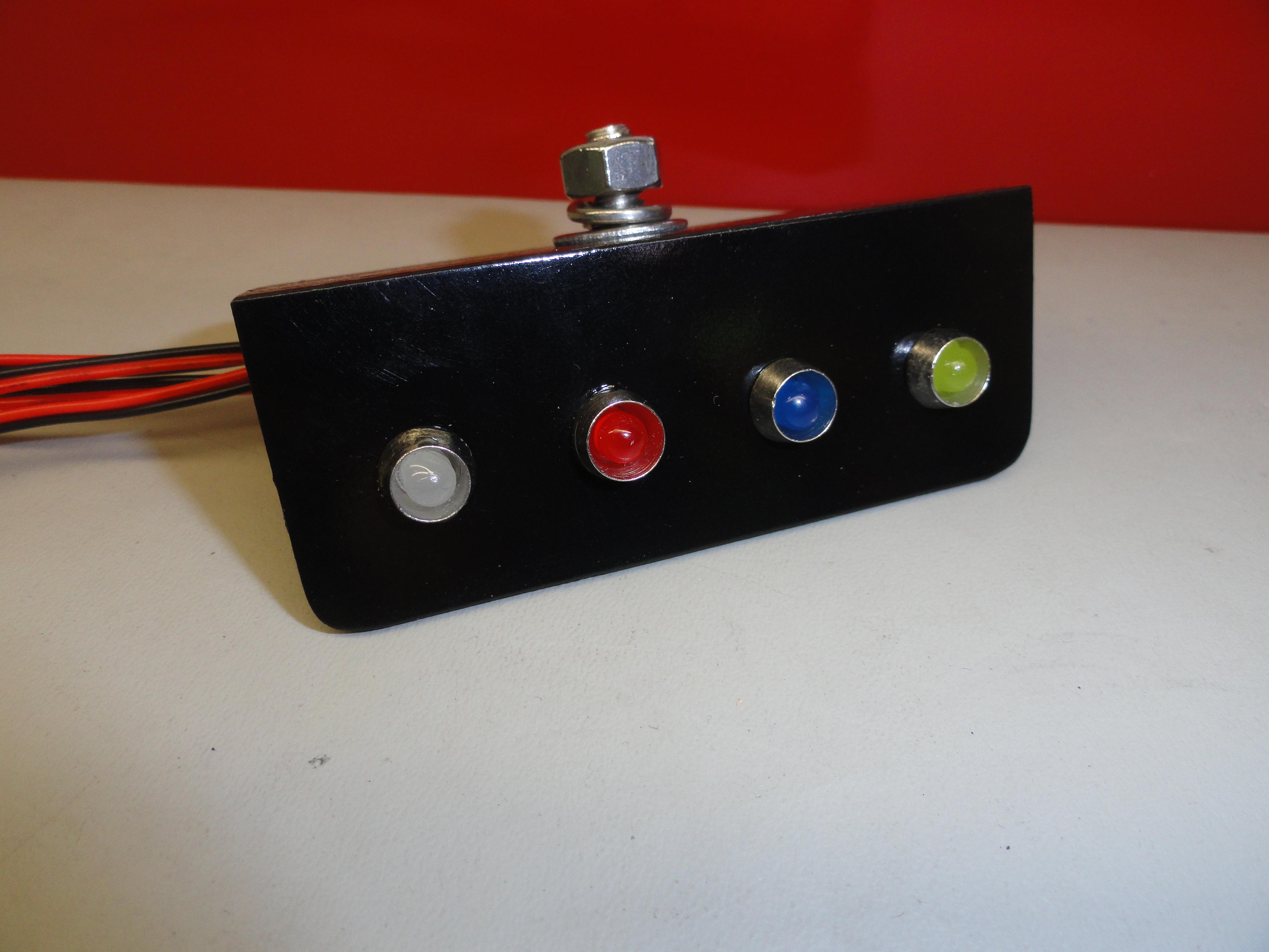
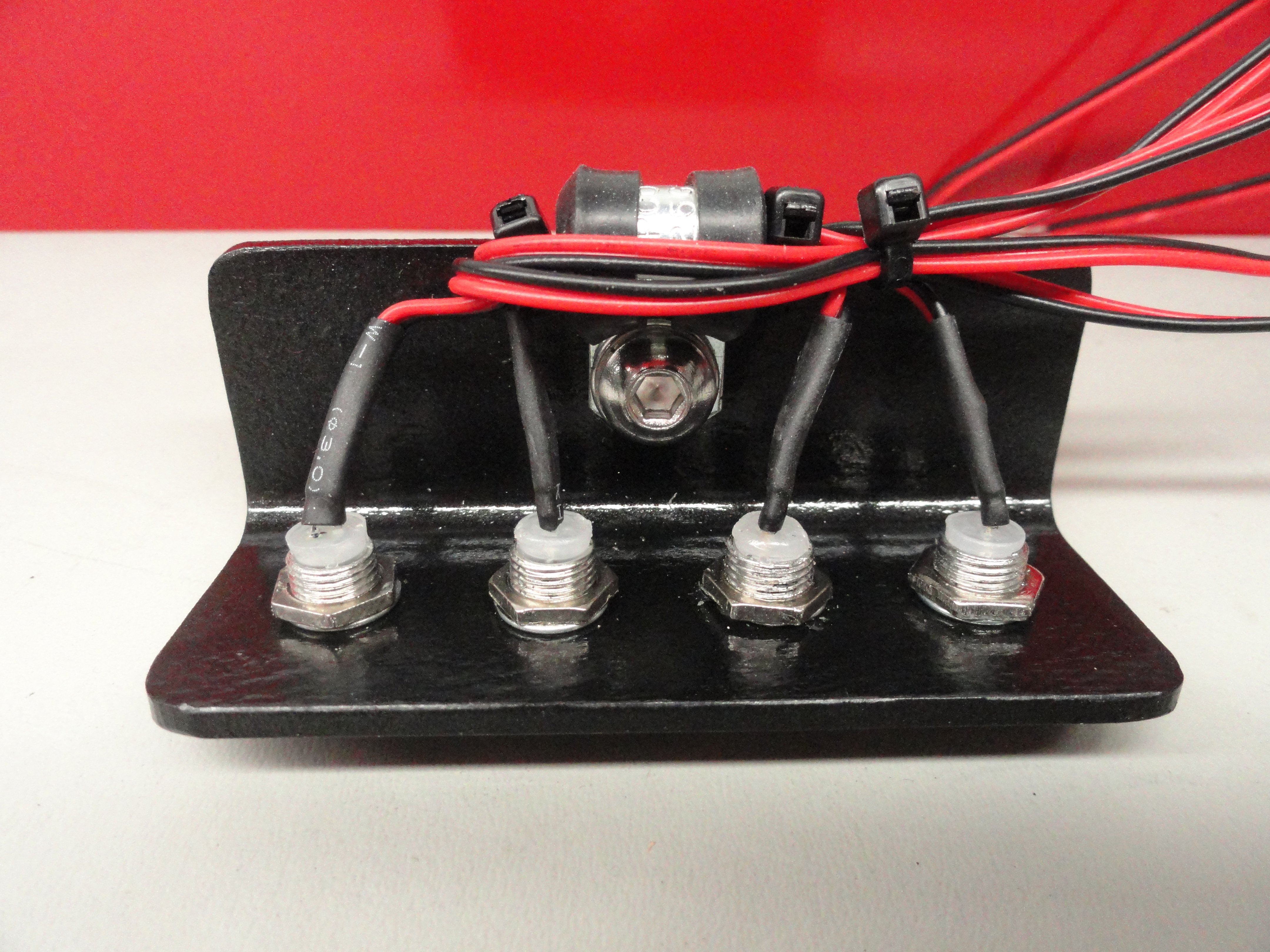
The LED Dash Bracket that comes with the Basic Kit has a stud sticking up for attachment under the dash. It is made out of mild steel and all associated hardware is stainless. Find a metal reinforced area of the bottom of your dash where the stud can come up through and bolt down to. Generally, to the left of the Steering Wheel and in plain site is a good choice, but this is owner preference. The bracket has a tapped 1/4" hole with a stainless bolt through it and associated hardware. This tapped hole keeps the bolt solidly captured making installation much easier.
All three Engine wires can be attached to the inner fender on the drivers side of the engine. Here is where they go:
(The Black 22 Gauge Wire goes to the Gas Tank Sending Unit which is covered later and does not go through the firewall.)
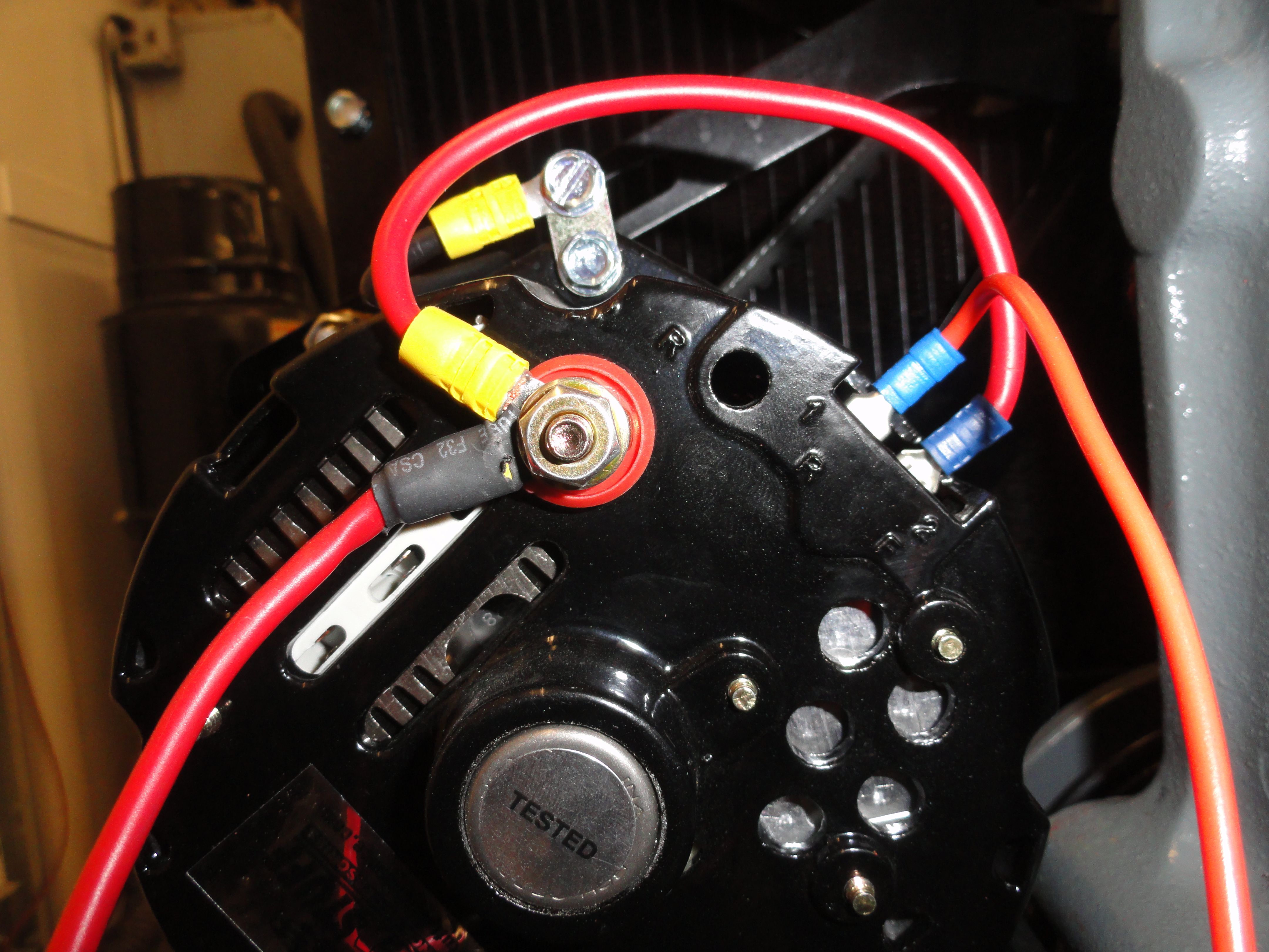
The Alternator Wire (Red) - Refer to the picture on the right. The wire that is going off camera to the right is the wire that is used for the Alternators Warning Light. If your vehicle is not equipped with a Warning Light system, chances are the Terminal on the Alternator is not connected to anything. If it is, it may be terminated under the dash somewhere. It is your choice to find the wire under the dash, or just disconnect it at the Alternator and connect the Red wire from our Black Box to terminal 1R at the Alternator. Of the two terminals with the smaller wires, it is the Inside one. The other small terminal (outside) wire is the Field Wire and an integral part of your charging system. These instructions cover all 10SI and 12SI type Alternators. Look through your particular Alternators documentation for the Warning System wire if your's is different. This is a critical connection for proper operation of your new monitoring system.
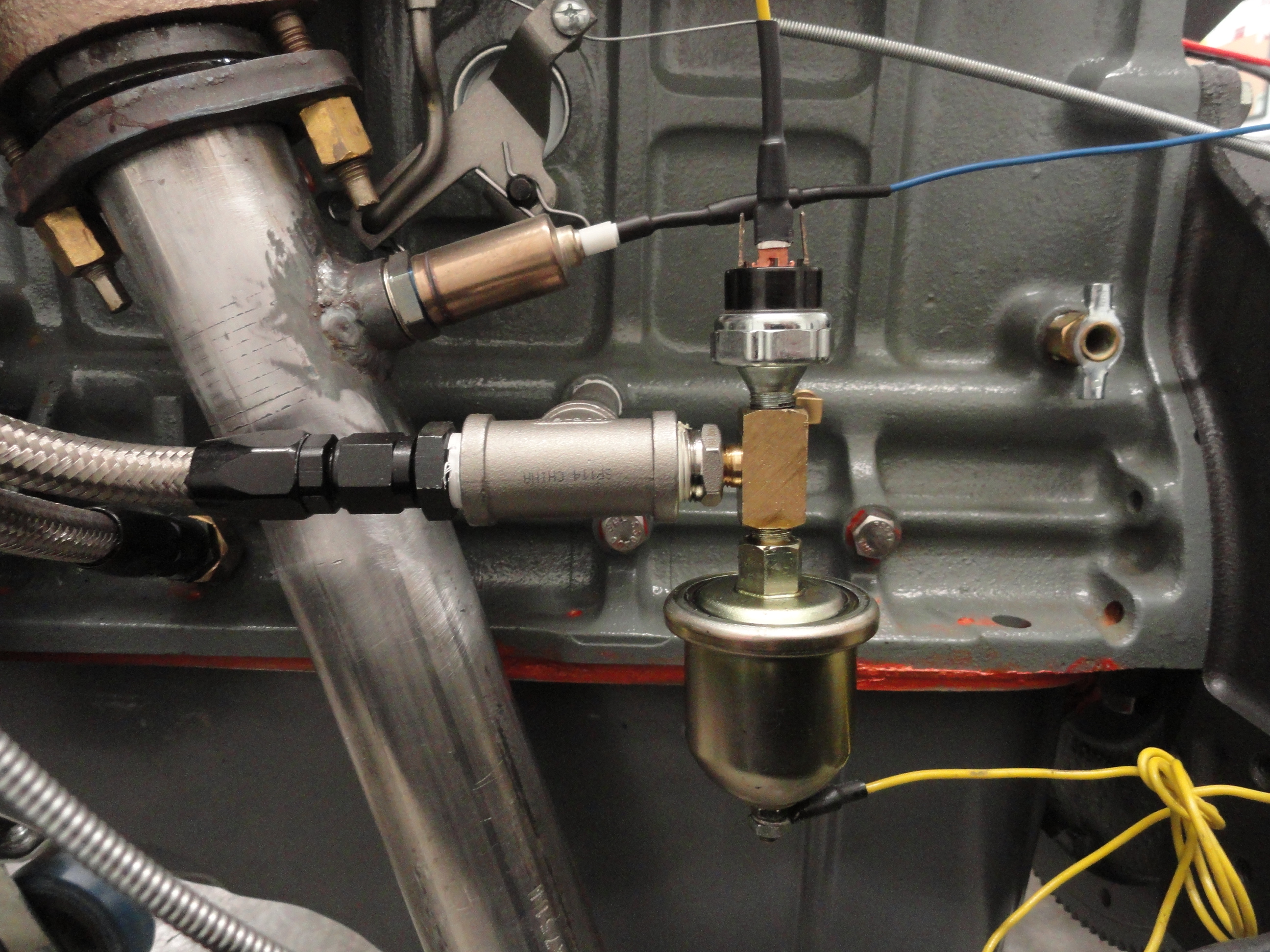
The Oil Pressure Wire (Yellow) - This wire connects to the top of the new Oil Pressure Sensor that you installed previously. Included in the kit are a few extra terminals so you can shorten this wire if needed. The spade terminal will ensure it stays put. Connect to the Center spade terminal on the sensor. The two other ones that are parallel to each other are for installation of an optional Hour Meter.

The Temperature Sensor Wire (Blue) - This wire has a custom lug for bolting down to the Engine's Thermostat Housing. For it to work properly, it needs to be the first thing and come in contact with the housing. If you have other things like clamps connected there, just ensure this sensor is first and makes good contact with the housing. This is an Automotive Grade Thermistor and can be adjusted from Ambient (room temp) to 257 degrees (F). More on that later. Bolt it down securely, then route all three wires using included tie straps for aesthetics.
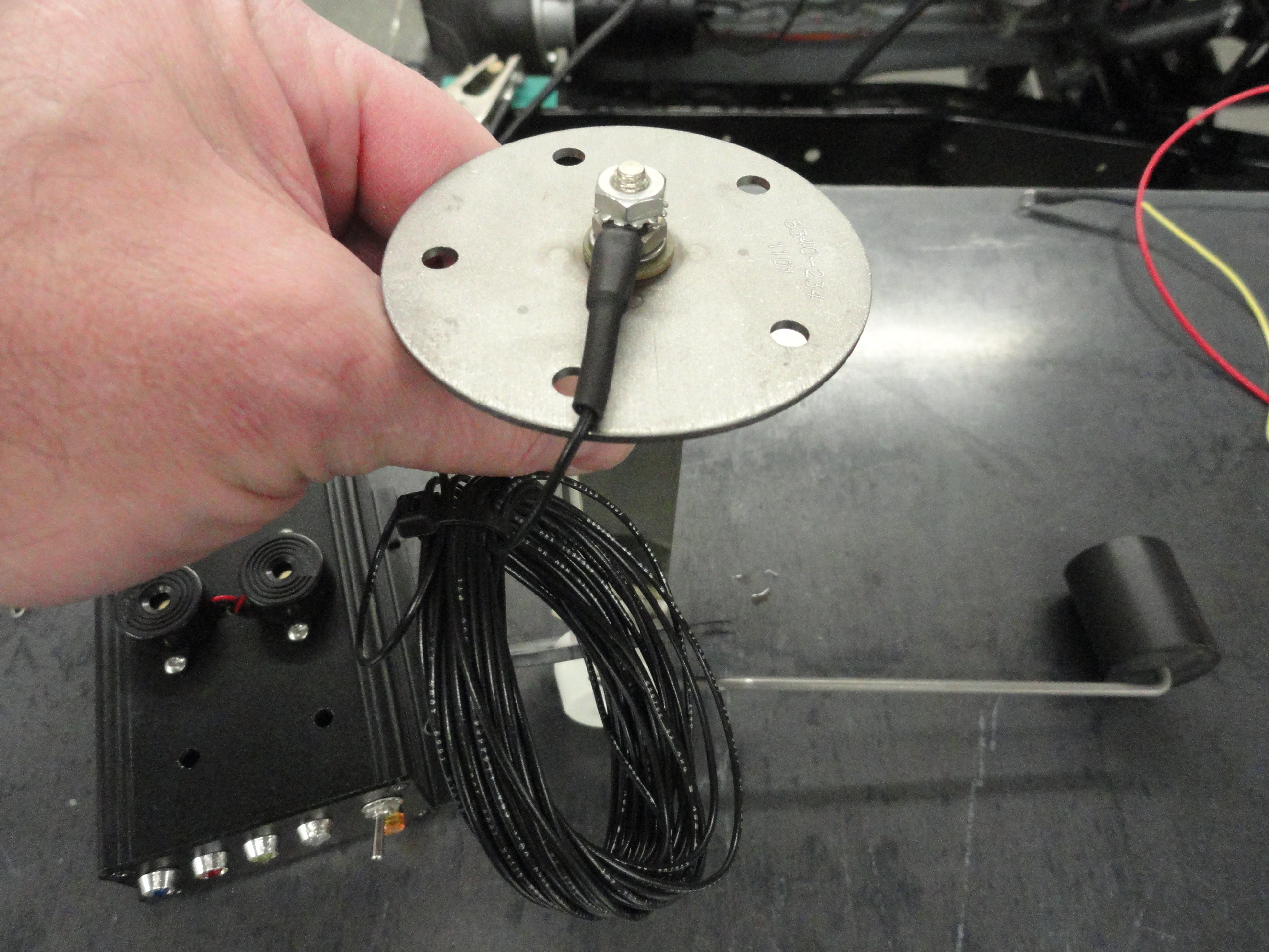
The Black 22 Gauge Wire also coming out the back of our Black Box is for connecting to the Fuel Sending Unit. This wire is extra long so that you can connect it if you have a frame mounted gas tank or an installation other than behind the seat. The Fuel Sending Unit is the float system that is mounted inside the gas tank. It has one wire terminal in the center of it that has one wire attached to it. This wire that is already attached goes to the Sending Unit Terminal on your Fuel Gauge. All we are doing is stacking our wire on top of the existing wire. Remove the nut holding the wire in place and install our Black wire on the top of the stack and tighten the nut back down. Route the wire as desired using the included tie straps.
In the wire bundle coming out the rear of the Black Box is a short (in comparison) Red wire. This is your power wire and should be connected to switched Ignition power. You only want this system powered when you turn on the Ignition switch. This is accomplished in many different ways depending on your wiring system. Sometimes it is connected direct to the ignition switch, other installations have this ability in an associated electrical box. Find a good place to connect the system to a switched power source. The Black Box has it's own on-board 10 amp fuse. This is not as much to protect our circuit from itself as much as it is to protect the Black Box from other systems in the vehicle.
Important - The ground (negative side) is accomplished through the vehicles ground system. The Black Box will get its ground from the 4 sheet metal screws connecting it to the metal kick panel, the sensors get their ground from the engine, and the low fuel warning ground is also through the vehicles grounding system. (The same one that gives the fuel gauge its ground to the sending unit). You want to be sure that ground from the gas tank, engine, and mounting point of the black box are at the same potential. On a Negative Ground system, this is normally a given. To test, with a multimeter set to read a short (continuity), touch one lead to the outside of the gas tank and the other to the vehicles frame. If you get a short there, check your engine to the vehicles frame the same way, then the firewall to the frame the same way. Lastly, the kick panel to the inside firewall the same way. If you read a short in those places, your grounds are intact.
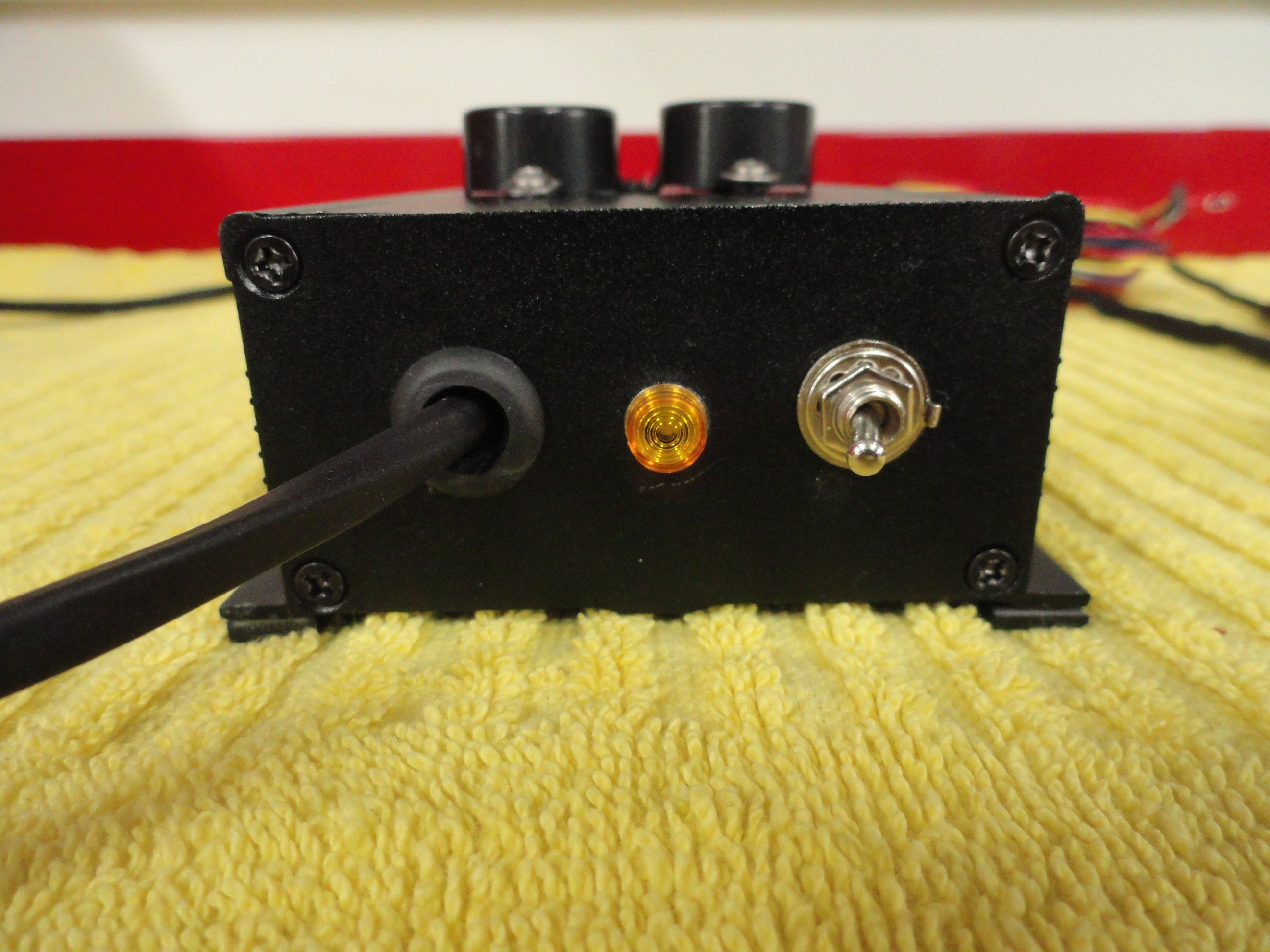
This system is equipped with a Supervisor Circuit which the sole purpose is to monitor the wire connection to the Thermistor sensor on the engine to make sure it is connected. Turn on the Ignition Switch and flip the Black Boxes switch to ON. The Amber Caution LED should not be lit. If it were lit, it would mean the Thermistor (Sensor on the Engine's Thermostat Housing) is not making proper connection.
Notice on Ignition ON you also have a White LED that is lit brightly. This is your Alternators Charging Circuit Warning light. Of course since you do not have the engine running, it is showing it is not Charging. If that light is ever brightly lit when the engine is running (a little above idle), you have a charging system fault. Rev the engine and that light will go out or very dim. This is normal.
The Oil Pressure light is the Red LED. It is not lit with just the ignition on because we have a suppression circuit incorporated so that the audible and the light do not go off when you just have the switch on. That would be annoying!
The Water Temperature light is the Blue LED. It is not lit ever unless the temperature reaches 220 degrees. If that ever happens, an audible alarm and that LED will let you know. If the Amber LED on the Black Box itself is ever illuminated, it means the wire to the Thermostat housing got broken or something happened inside the Black Box (unlikely).
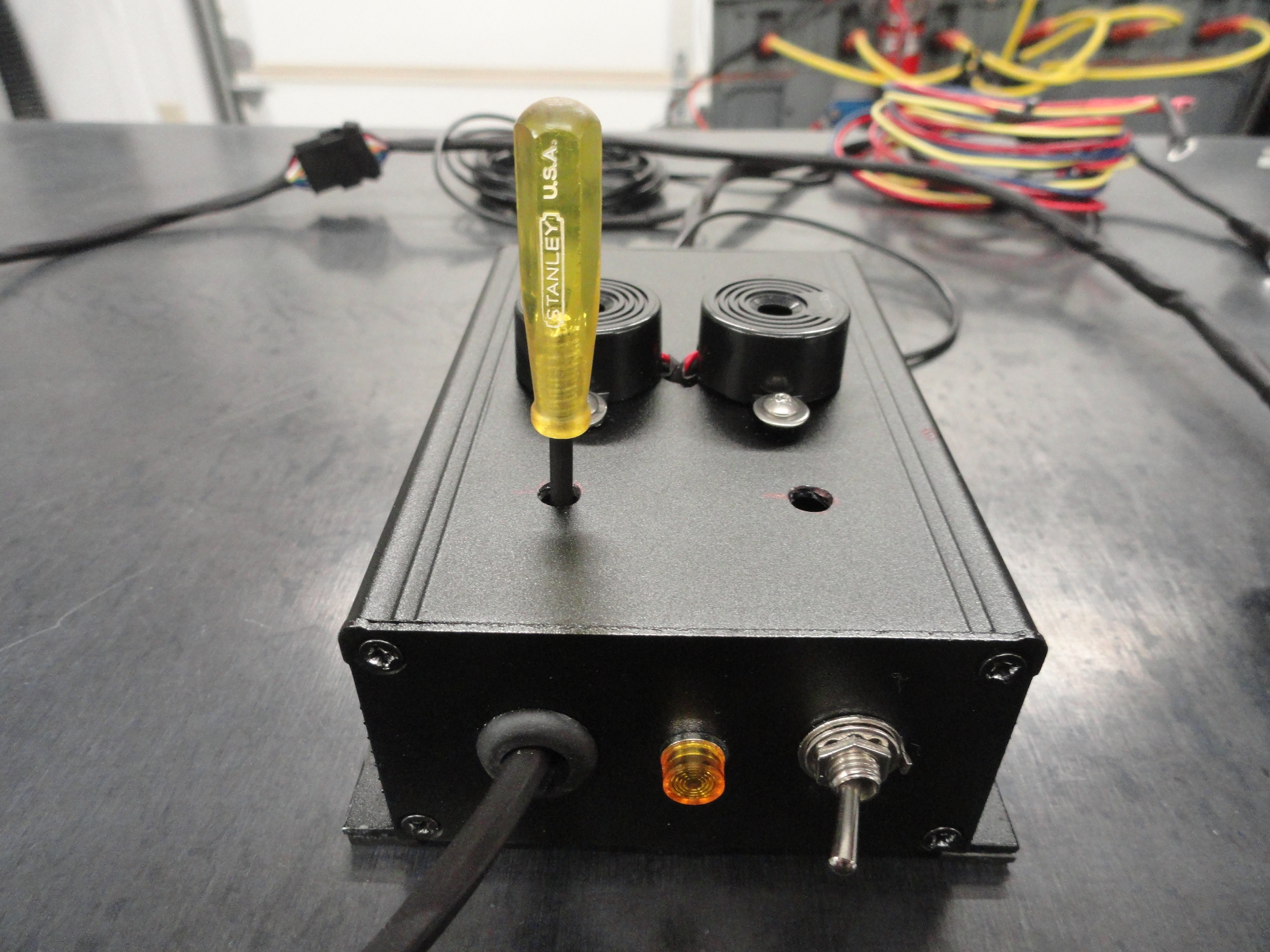

The 220 degree threshold is fully adjustable by turning the potentiometer inside the Black Box. There is a hole drilled above this potentiometer which is labeled on the top of the Black Box. Very carefully slide a very small flat tip screwdriver into the slot on the Potentiometer to turn it to your desired temperature. It is set from the 'factory' at 210 (plus or minus 10) degrees. Do not risk shoving a metal screwdriver into that hole! To make your own proper screwdriver, wrap electrical tape around a metal one to within 1/16th of the blade bottom and all the way up the shaft. Shrink Tubing is even better. Do it like in the pic and you are good to go!
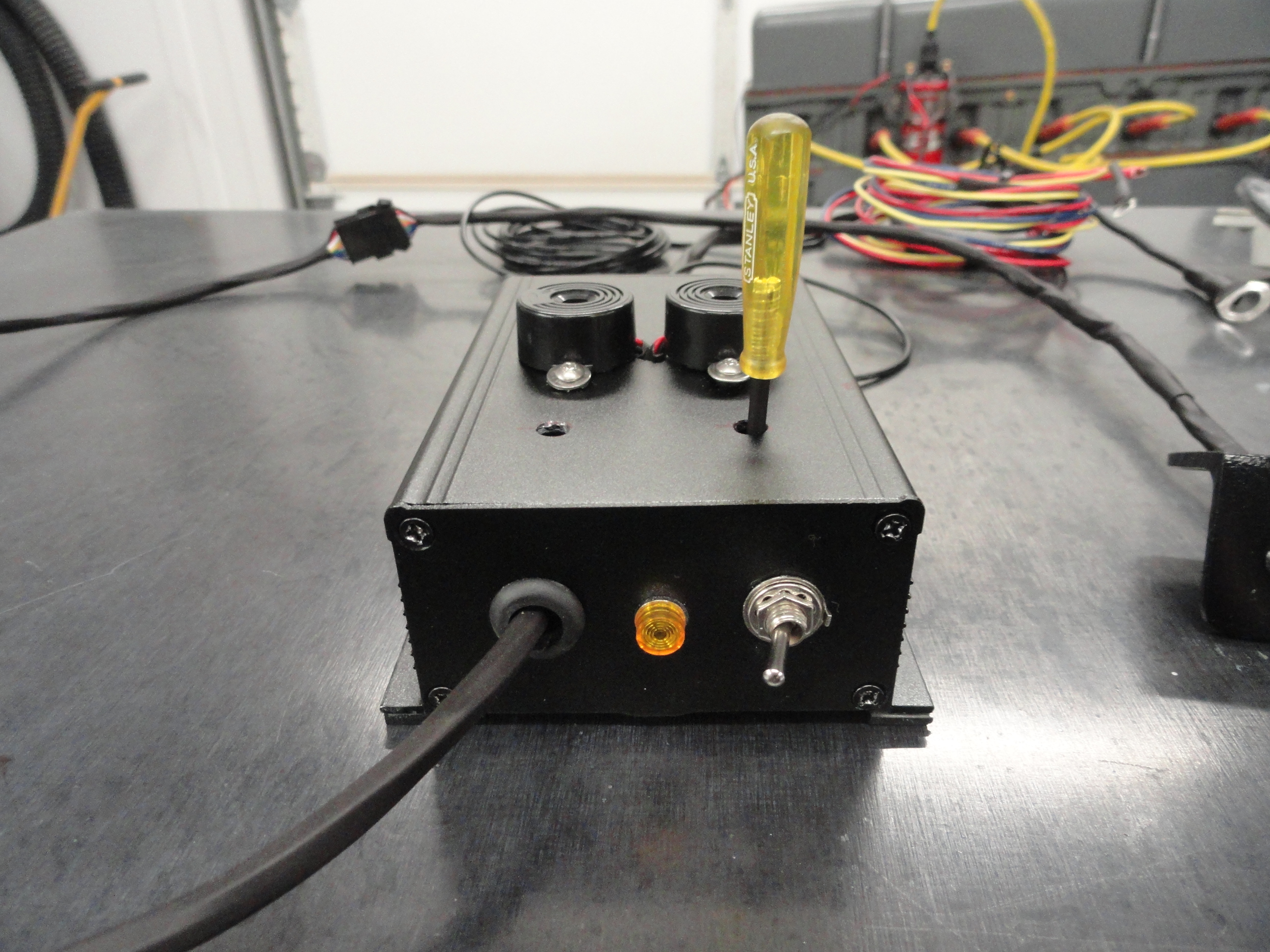
The Low Fuel Warning light is the Amber LED. Depending on your sending unit and if your gas gauge is a native 6 volt or 12 volt, this function WILL need to be adjusted with the aforementioned screwdriver. The beauty of this adjustment is you can adjust it anywhere from a half-full tank to completely empty! So if you live 30 miles from the nearest Station, you may set it differently than the person who has a Station down the street. To set it properly, do a little testing. Put a 5 gallon can of gas in the vehicle and run it out of gas. Put two gallons in the tank, then with that plasticized screwdriver, turn the Fuel Potentiometer on the Black Box until the light barely lights. You can of course do this with any amount of gas you wish. This is a great secondary system to test your fuel gauge's accuracy. To save you from this initially, the Low Fuel Threshold is 'factory' set to light up at approximately 2 gallons, but understand this is a guesstimate since each system behaves differently.
The only way to test the Water Temp Circuit is to take something like a good blow dryer or something hot (not open flame) and heat up the thermostat
housing near the Thermistor Lug. Do not point it at the Lug Housing or wiring itself! With the ignition on, and the Black Box switched to ON, once it
reaches 220 degrees, the Blue LED should come on and a very loud Audible will sound off letting you know it's working. If you insist on trying this, do
not overheat (beyond 257 degrees) the Lug Housing and do not melt your wiring and the high temp silicon holding the Thermistor into the Housing by applying
way too much heat to it! Once the heat goes below 220 degrees, the alarm will shut off.
NOTE: Just so you understand better what is going on here, the Thermistor does not magically detect the true water temperature, rather it detects
the temperature of the Thermostat Housing at each temperature and correlates the result to the specific water temperature. So, if the true water temperature
is 180 degrees, the Thermostat Housing could be at 150 degrees (due to the fan blowing on it, metal heat dissipation properties, etc). In that case, 180
EQUALS 150 to the sensor. When you have an overheat condition, the sensor will detect the Thermostat Housing temperature that correlates to 210 degrees of
water temperature. This is how all modern cars are set up for cooling fan and warning operation using the same automotive grade technology. It gives us
very precise results.
To test your Oil Pressure Warning Circuit you must have the engine running. Take a short jumper wire and ground one side to the Tee on the Oil Pressure connection at the engine block and the other side to the wire connection on the new Oil Pressure Sensor. With Ignition ON and the Black Box switched on, and engine running, the Red LED will light and the Audible will sound off. Remove the jumper wire and the alarm will go away.
This being a new product, we try to anticipate what could go wrong and make sure our system can handle every anomaly, however, there can always be unforeseen
issues, so here are a few things that could help.
This system has been thoroughly tested and uses long lasting components that were carefully selected for their quality and longevity. The circuit was carefully designed and many hours went into consulting with various engineers prior to calling this a finished product. Even so, there is no greater feedback than that from the end user. Your feedback is critical to the success or failure of this system. Please comment on the installation, instructions, quality and operation in the DTN Forums here: DTN Forums.
Don't forget to take a look at our other unique products and systems. We strive to provide items that are not found at the usual places and we pride
ourselves on the superior quality borne from the sincere understanding that we are here to make friends.