


Deve's Technical Network
1947-1955 1st Chevy Trucks
216/235/261 Engine Solutions & More
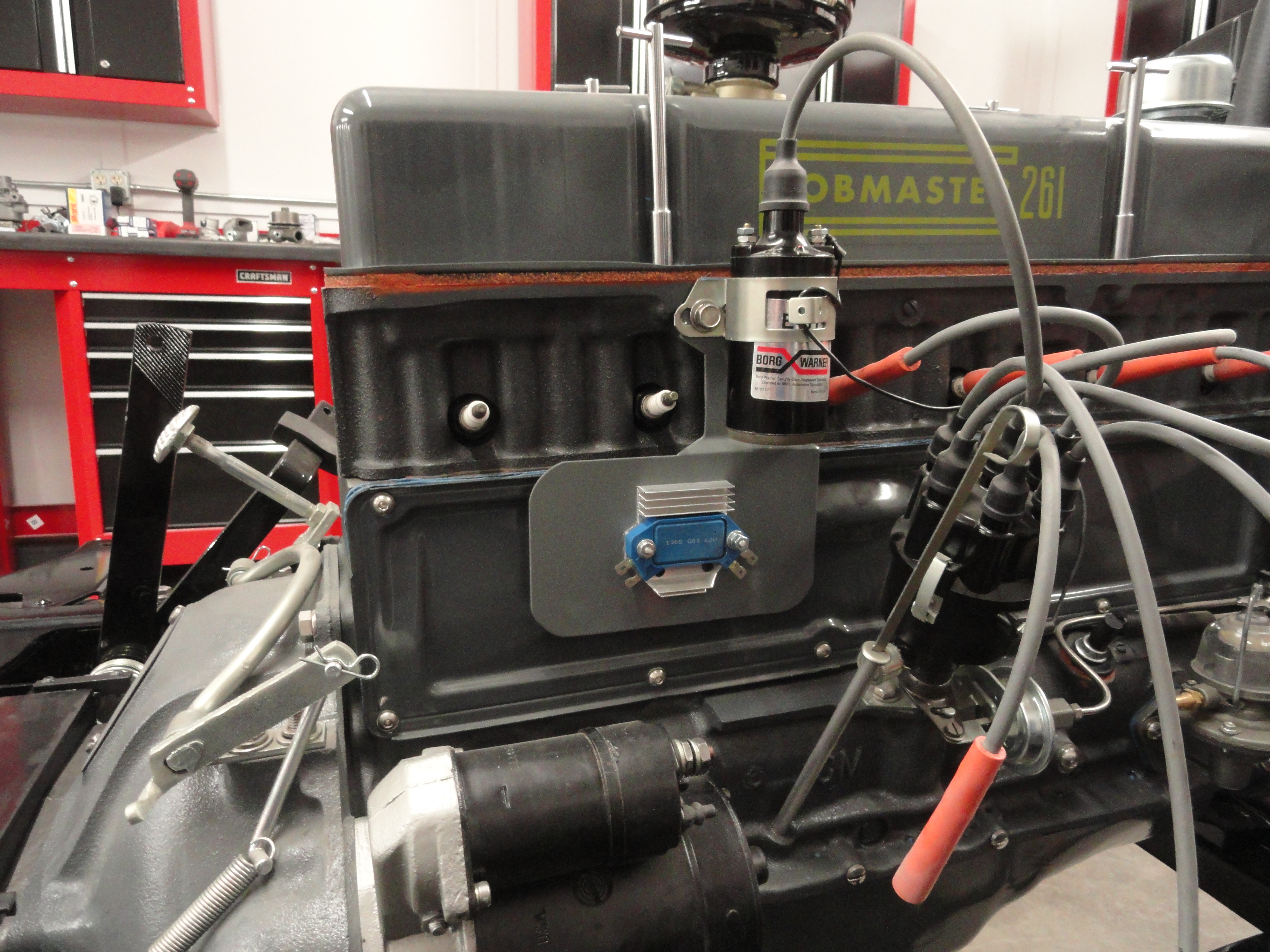
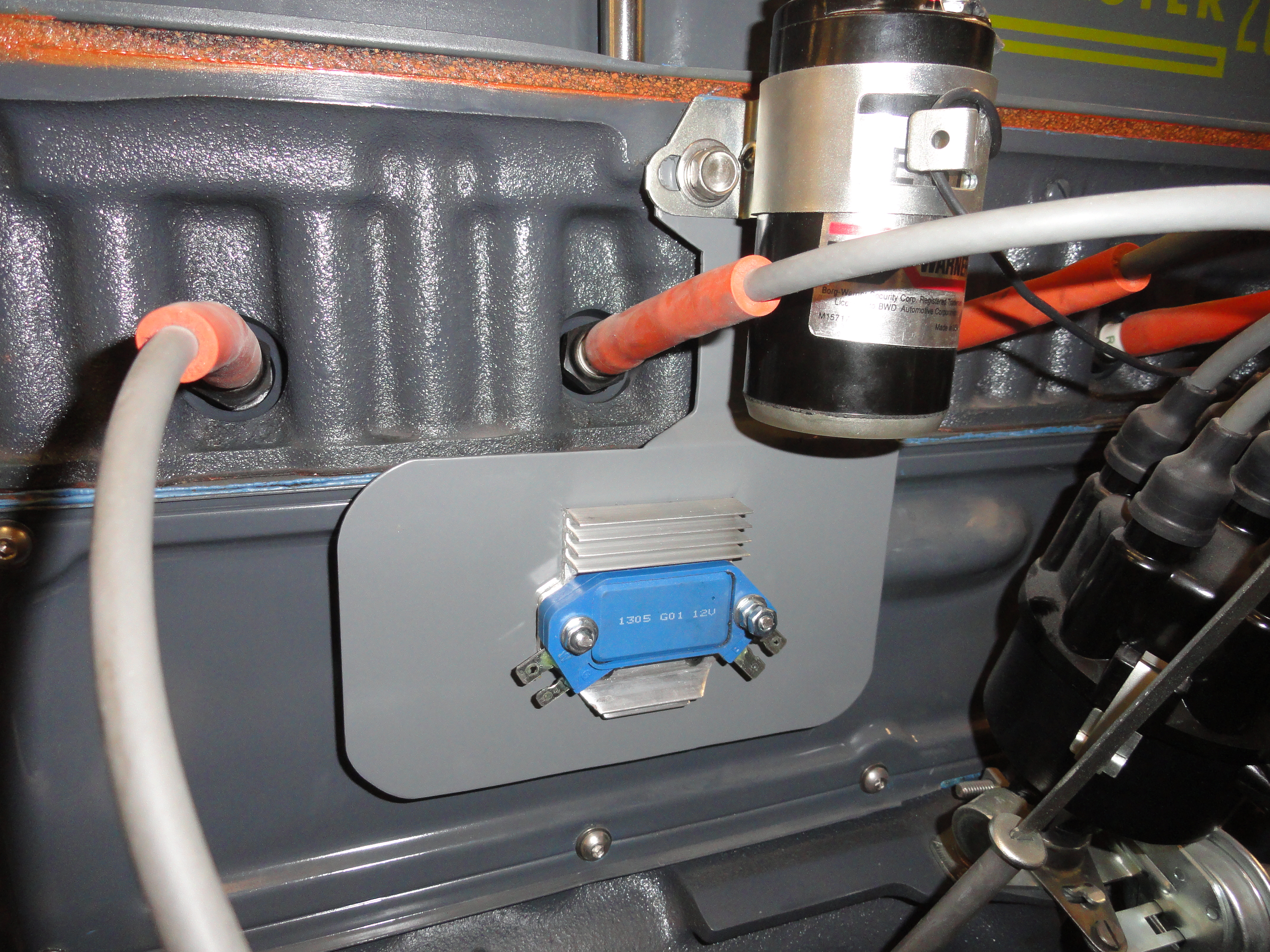
I wanted the HEI Module very close to the Distributor and Coil, so I made this plate that bolts on to the coil bracket. Then it occurred to me that a person could mount their Ignition Ballast Resistor on this plate as well if you don't want it on the firewall. This mount uses the Coil Mounting Bracket and allows air to flow across as well as behind it for better cooling, and if you decide you just can't stand the look, you could use an old Delco-Remy Regulator Box, gut it and place it over the top of the module on this plate giving it more of a retro look.
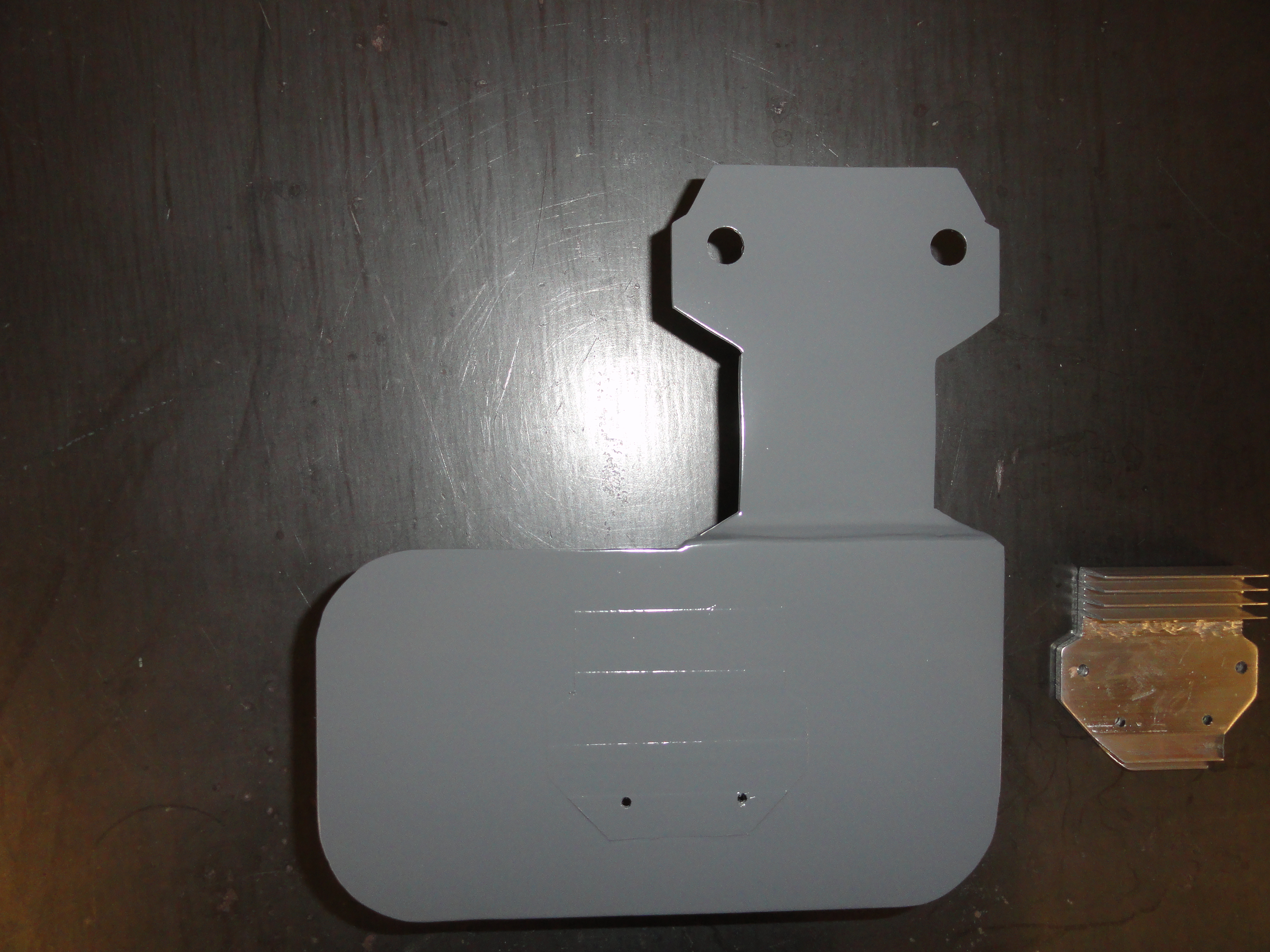

Start by getting some scraps of 12 gauge sheet metal, one is 3.5 x 4 inches, the other is 3.75 x 7 inches. For someone who does not have a fabrication shop complete with metal bending equipment and waterjet machines, it's just easier to build this out of two pieces. The reason is the bend in the center. Remove your engines coil bracket and trace the pattern on the 3.5 inch width complete with the hole placement. Then narrow that piece so that you can more easily get to the spark plugs by trimming off 5/8" from each side as shown. Notice the 45 degree angles on the transitions on both top and bottom. On the bottom of this piece (opposite the coil bracket trace) place a mark 1/2" from the bottom all the way across. This is where you will be bending. Put a 45 degree bend as shown. I used my vise and clamped that 1/2 inch inside the vise and just pulled it to 45 degrees with another piece of flat metal for uniformity. This is to get over the engines side cover as well as give it better air circulation. Drill your coil bracket holes using a 3/8" drill bit.
With the top properly shaped, I took the second piece and made round edges everywhere except where it will be welded together. Use whatever you have laying around the shop to mark the rounded edges. I used the cap off a WD40 can. Round as much or as little as you like. Its only for decorative purposes and to eliminate sharp edges. Once you have it rounded everywhere except the attachment point, place the top part flat on a table, elevate the bottom part with some wood shims, or whatever you have laying around the shop so that the whole bottom part sits a little less than 1/2" higher. Once you have it positioned correctly, weld the two pieces together using proper weld techniques so you do not warp the metal. Weld on both sides and then grind to suit.

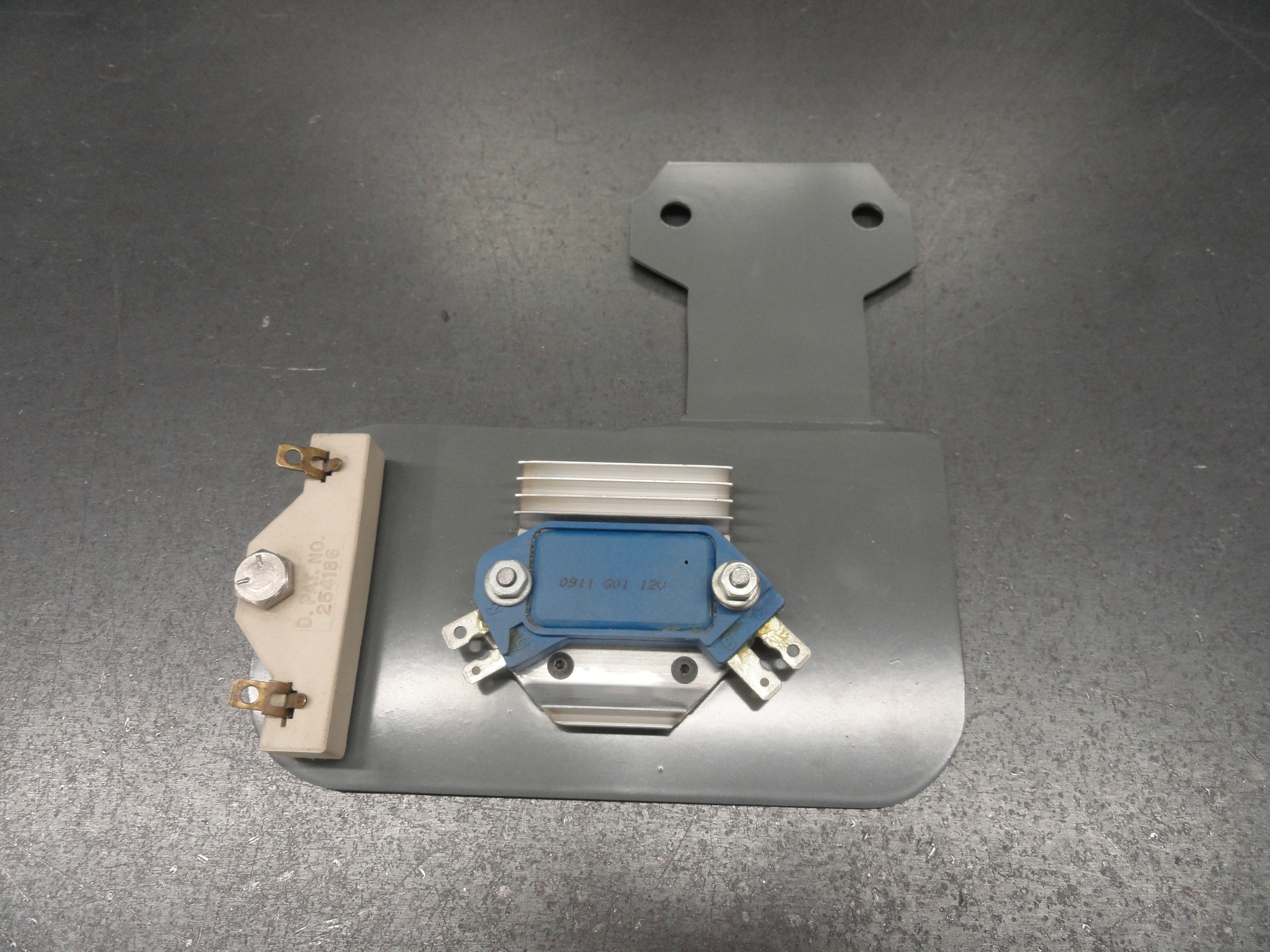
Since the HEI module requires a solid ground and heat sink, I traced the heat sink on the bare metal and taped that part up so it would not receive paint. I marked the holes for #10 mounting screws, tapped them and ran the screws in from the back. This would provide the most secure means of ensuring its solid and the ground will always be as good as it gets. Tape the coil mounting bracket area as well for proper grounding, then paint it the color of your choice. I had to remove the bottom fin of the heat sink with my dremel tool in order to mount the HEI module. Once painted, remove the tape, install the screws and enjoy your new mounting plate!
NOTE: If you are using this for the purpose of an ignition ballast resistor, you will want to mark and drill your holes accordingly. This is the ideal place for the ignition ballast since it gets hot and has been known to ruin paint! It is not necessary to tape anything for the ballast resistor since it does not need a ground to work properly.