


Deve's Technical Network
1947-1955 1st Chevy Trucks
216/235/261 Engine Solutions & More
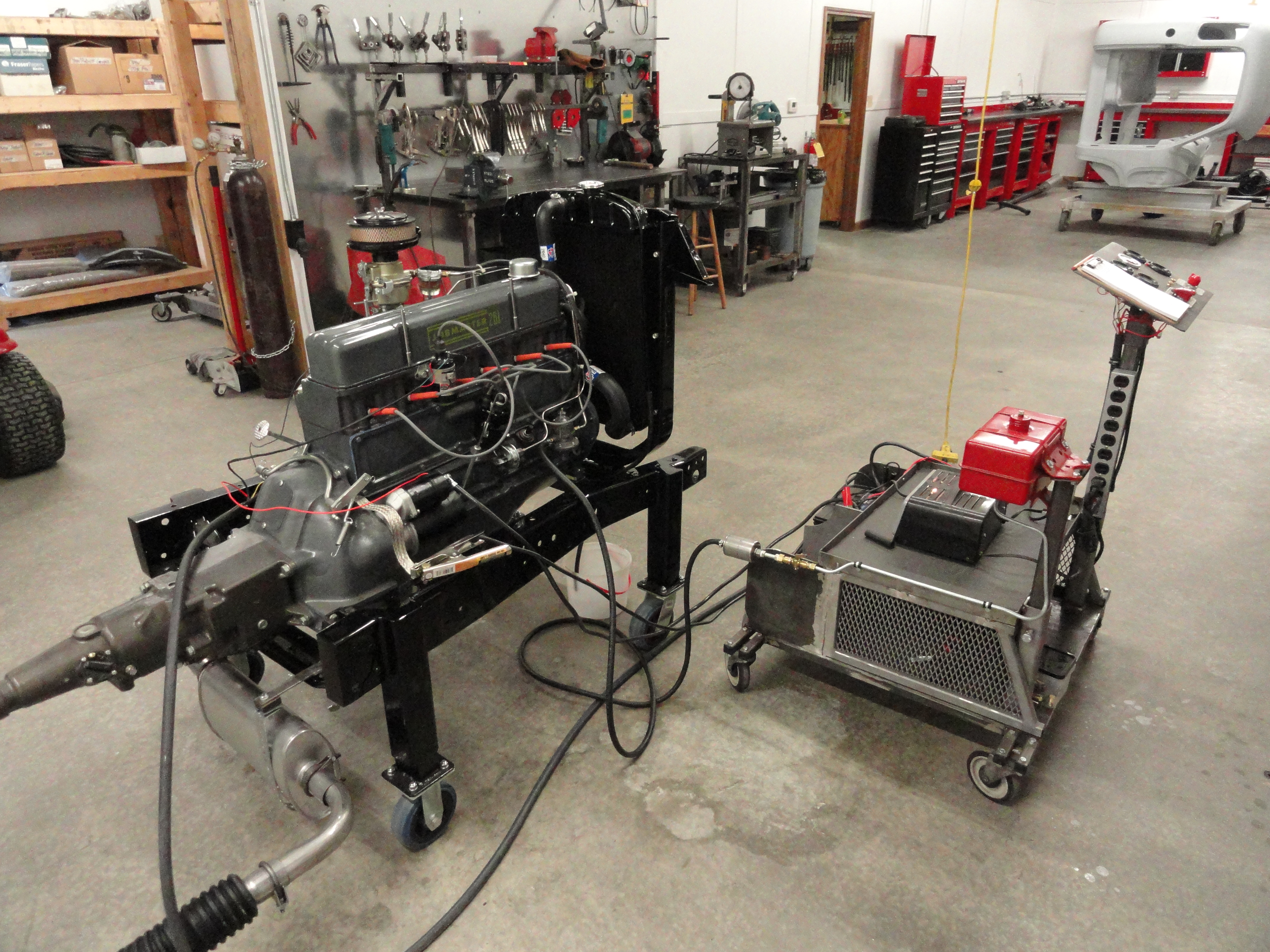
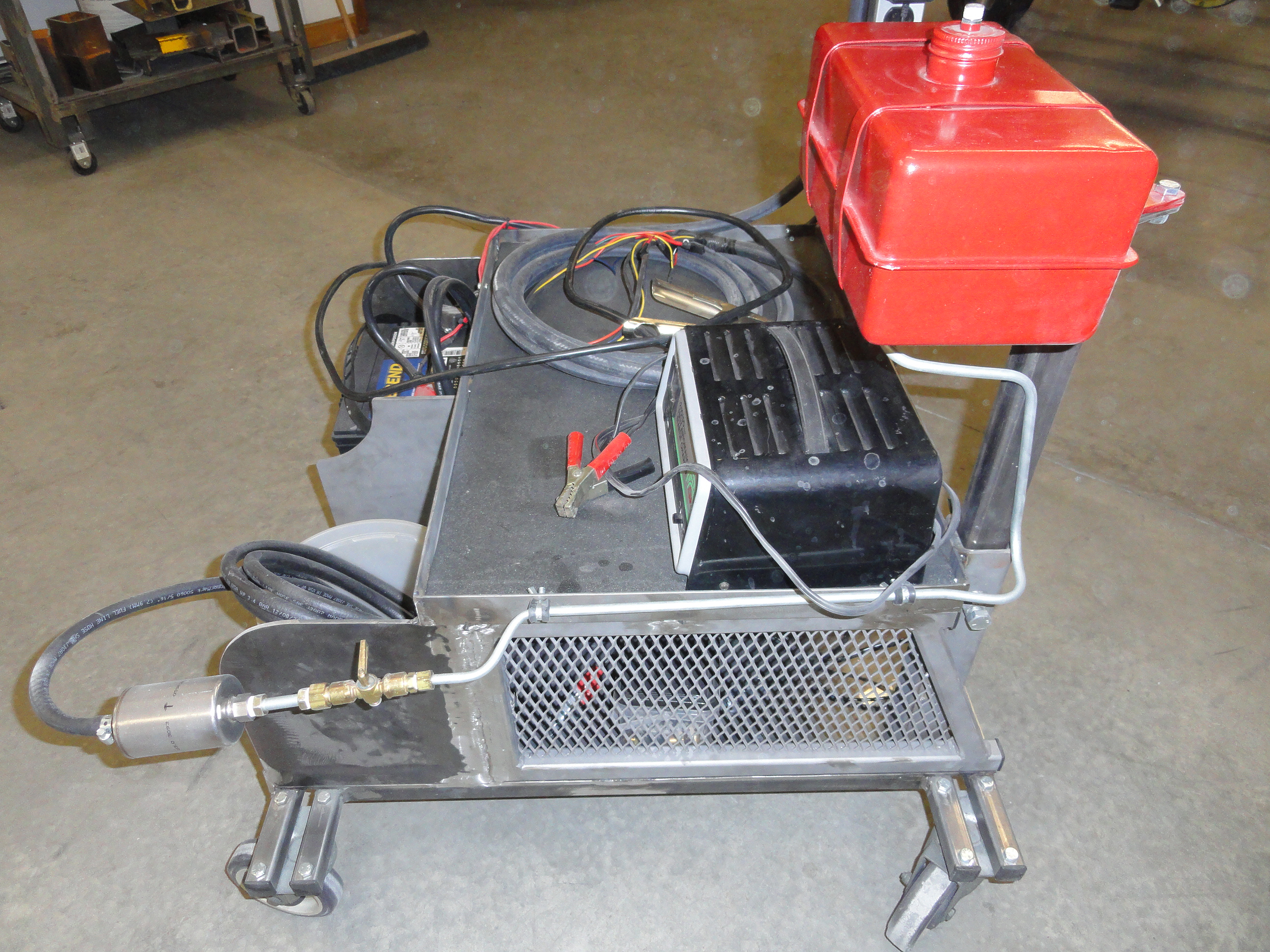
Most guys incorporate the Electrical and Fuel system stuff on their Engine Stand. That's fine and all, but imagine being
able to roll a small cart up to any vehicle OR an Engine Stand no matter where it is? This 30" x 35" Start Kart has a
relatively small footprint while delivering the versatility to be used with an engine cart, a newly restored chassis, or
any vehicle you have with ease. Roll it up, make the connections and you are in business. We added fuel capability to give
you everything you need for both fuel system AND electrical systems troubleshooting.
Source for the hardware is McMaster-Carr. Source for gauges, electricals, etc is Amazon.
All Gauges and Switches can be exchanged for similar models from other sources.
*Caster City casters have a really nice double locking feature.
The best way to approach a project like this is to decide on how we want it to work, look, feel before we get started. This is where Solution Criteria
comes into play. I have this policy of making the Solution Criteria set in stone no matter how hard it is to accomplish.
Of course the cool thing about fabricating is that you can do it your own way. In the end, if you have a nicely rolling cart with a solid console and places to store a few batteries, you are good to go. Why a few Batteries? You may find yourself in a situation where the battery in the truck needs recharging or is 6 volt, and the new battery you are exchanging is 12v or needs recharging or testing. I created this cart awhile back and am just getting to describe how to make it now, so forgive me if I leave out a few details. Ask as many questions as you want.

Start by making a solid and square platform by cutting a piece of 1/4" plate steel to 27" x 30". Then cut 4 each of 1" square tubing each measuring 35" in length. Cut two 24-1/4" pcs of 1x1 as filler to complete the platform. Now, take two of the 35 inchers and place them across the 27 inch width of the platform. On the 35 inchers, measure 4 inches from each end to get them placed perfectly in the middle. Clamp the outside one onto the platform piece securely on each end. Make sure there is an equal 4 inches sticking out of the platform. Place a caster on top (upside down) and place it flush with the outside of the 1 incher, then place your second 1 incher so that it sits flush with the inside. Mark all of the caster holes for drilling and go ahead and drill them out and bolt the casters to the rails as shown.
Once they are bolted solid to the 1 inch rails, weld them on to the platform. Follow proper welding procedures cleaning both surfaces, removing the mill scale and tacking things so as not to warp the metal. In the end, you should have a nice, rolling platform. Now, install the 1 inch 24-1/4 inch long pieces across the other dimension to complete a nice 1 inch boxed structure under the plate. The reason why it's always a good idea to read these instructions all the way through before making any cuts is, if you got wheels that have a shorter bolt pattern this 24-1/4" dimension could change. Hopefully you are good to go!

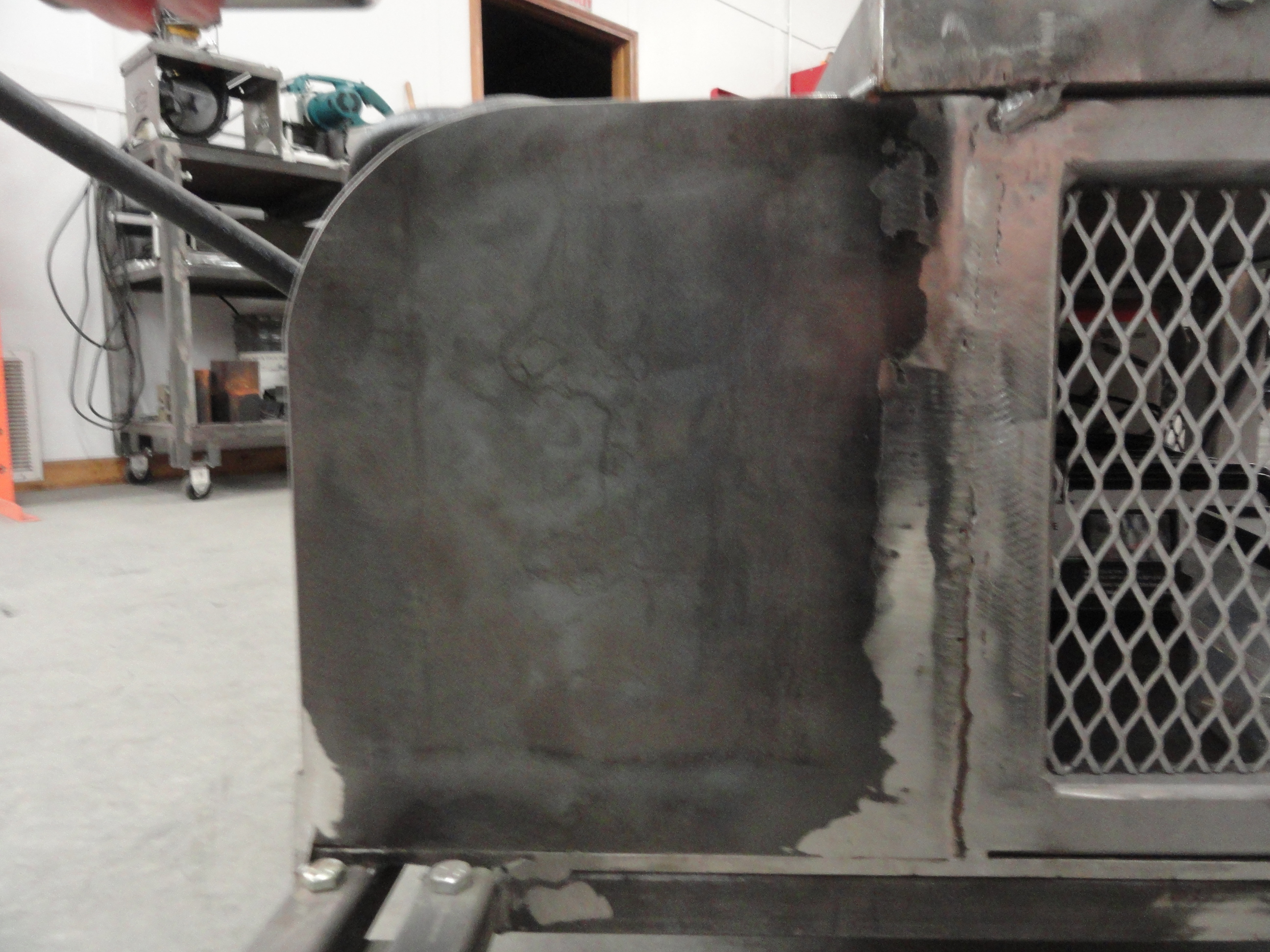
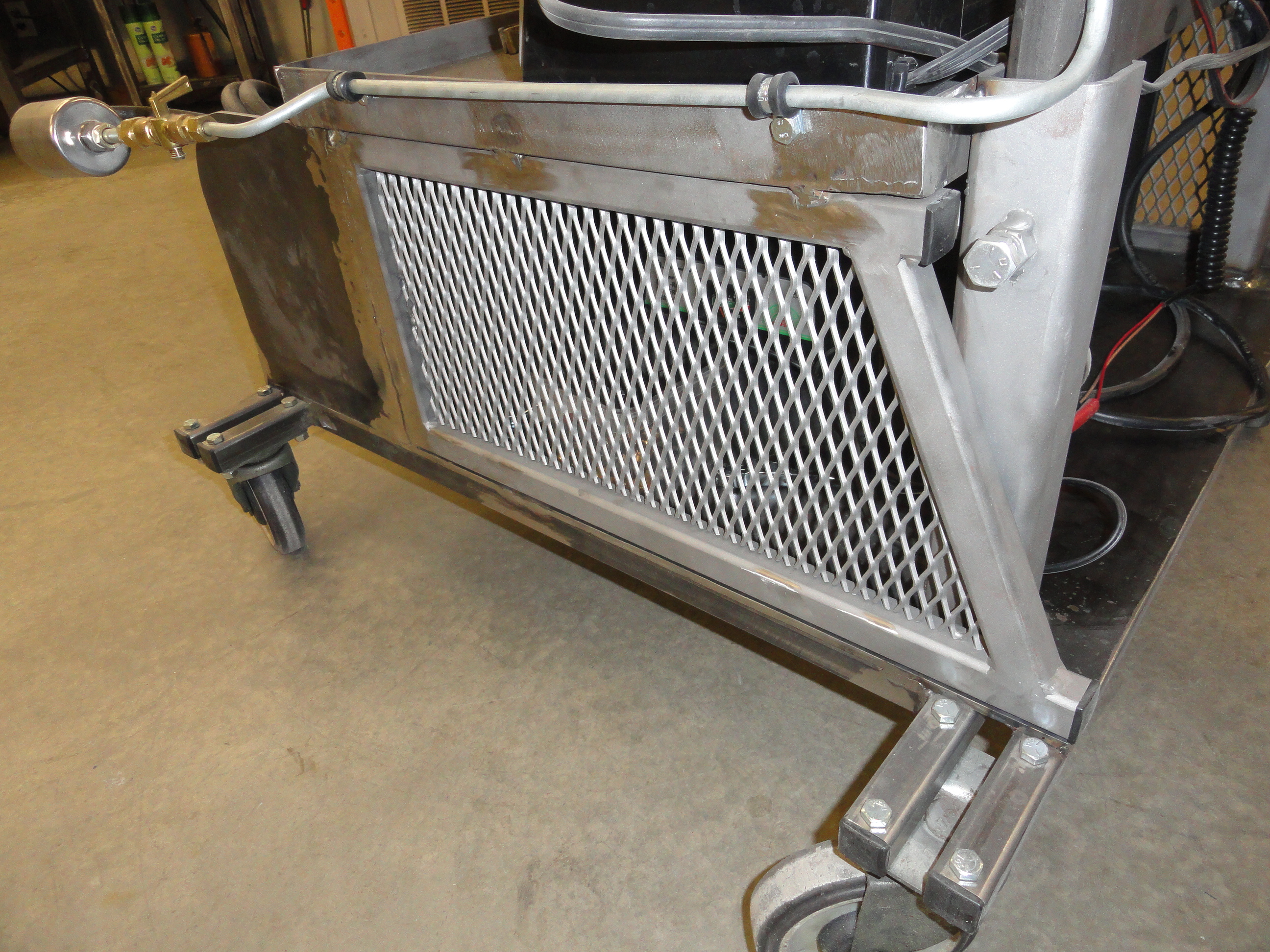
The next step is to make the two sides as shown. These frames are made out of 1 inch square tubing with the metal extruded screen on the inside. Start by cutting the four pieces, first one on the left vertically is 10 inches, second one on the top is 16-3/4 inches, the third one on the bottom is 21 inches. To find the size of the last one, lay out your pieces on the table and square them up really good, then place your final 1 inch piece across the angle and mark both ends. It's pretty darn close to the same 10 inches, but lets not get in a hurry. Once you have found the angle make the cuts on each end so you have a frame as shown. Weld the frame making sure to keep it flat so it comes out nice and square. Do this exact paragraph over again so you have two frames that are identical.
I found a scrap piece of this metal screen and thought it would be nice to be able to see inside the Kart. If you think thats too frivolous for you, just trace out the inside of your frame and use regular 3/32" plate. If not, I felt it adds a little personality to the project. Whatever you use, lay the frame over the material and trace the inside with a sharpie, then weld the material in place. Next we want to weld the frames to the Kart.
For placement of these frames, it's critical we place them so that you have a full 9 inch battery width and some wiggle room. Designate one of the 27" sides of your Kart as FRONT, then measure 9-1/4" in from the front. This is where you will place the leading end of those two frames you made. It's okay if the frame sticks over the BACK just a little. Square up your frames for welding them in place. I like those 6" welding magnets for this, but whatever you use, the frames should be nice and straight and level.
Across the front of the Kart, from frame to frame, we want to cut out a piece of 27" by 10" inch 3/32" plate steel and weld it securely in place. I used 1/4" plate on mine, but whatever you have for structural plate is fine. Once that plate is welded and your frames are secured, cut out three of 1/4" by 9" by 10" pieces of plate steel for the sides of the battery box and the middle. The thicker 1/4" is better for this since it needs to be pretty stout because we are only securing it on two sides. Use a large coffee can or whatever you can find to round off one side of two of the plates as shown. Weld the sides in as shown. The middle one is a little different profile.
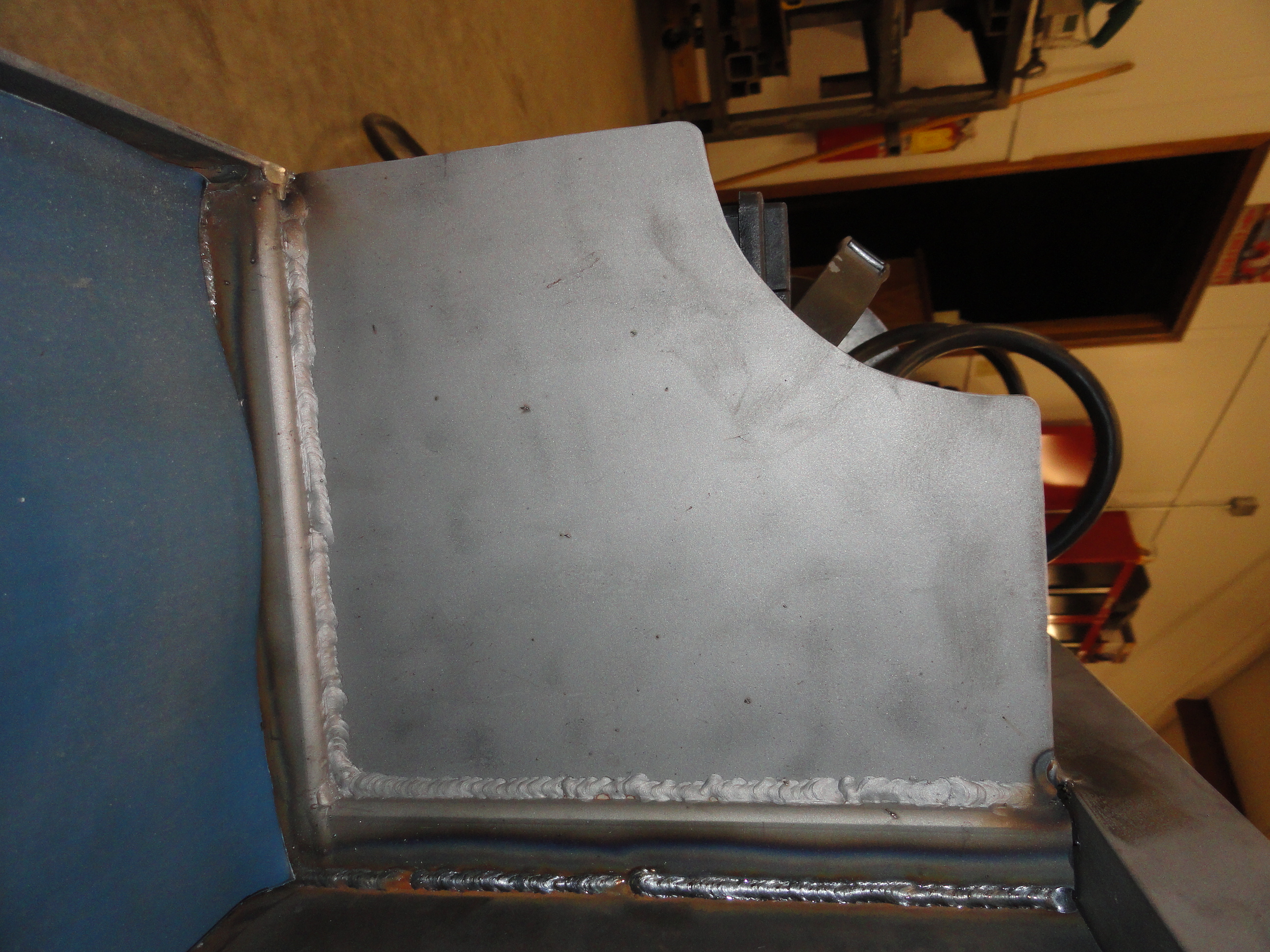
You will see on the right pic that there is 1 inch square tubing involved in these battery pockets, but it was totally unnecessary and served no useful purpose. If you weld them in straight and true, you will have a very nice stout Kart. See your work beginning to take shape? I love it when a plan comes together! Now we need to make the top shelf...
The top shelf measures 27 inches by 18 inches. Cut your plate steel to 26-3/4" by 17-3/4". Then with some 1/8" x 1-1/2" Angle Iron, make a nice border around it. Cut your angle iron pieces with 45's on the ends like a picture frame. Do this carefully so that in the end you have a nice lip all the way around the shelf. Weld your new shelf into place using the back of the carts angled sides as your guide as shown.
On the back of the Kart, we need to put two 2" square tubing vertical pieces in each corner. These will act as receivers for our gas tank and our console. To prepare the 2 inch for welding, cut two 12" pieces of 2x2 and drill a 1/2" hole at 3 inches down on one side. Thread a 1/2" nut onto a 1/2" bolt all the way to the head. Clamp the bolt in the hole and weld the nut onto your 2 inch. Remove the bolt and then test to make sure you can tighten/loosen by hand. This acts as the hold-down for the 1-1/2" mast that goes into it. Since gravity does most of the work, I felt it only needed one bolt/nut combination on each receiver. Place the 2 inch as shown with the bolt facing to the outside on each side and weld it in place.
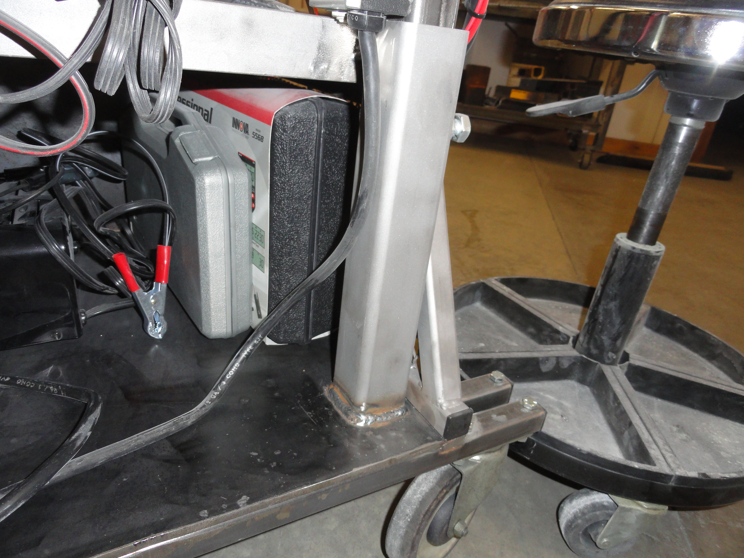

Now cut two 1-1/2 inch square tubing with 3/32" sidewalls. One of them cut to 24", the other to 32". Place the 24" one on the right facing the front of the cart inside the 2 inch receiver. This is your gas tank mast. Place the 32" one on the left. The taller one is your console mast. Tighten the bolt down to make sure you can secure them tightly. This is important for grounding purposes. The way you secure your gas tank to the top of the 24" mast will depend on the gas tank hardware you have. Mine is as shown, but yours will probably be different. Do what makes sense and be sure to keep the tank grounded.
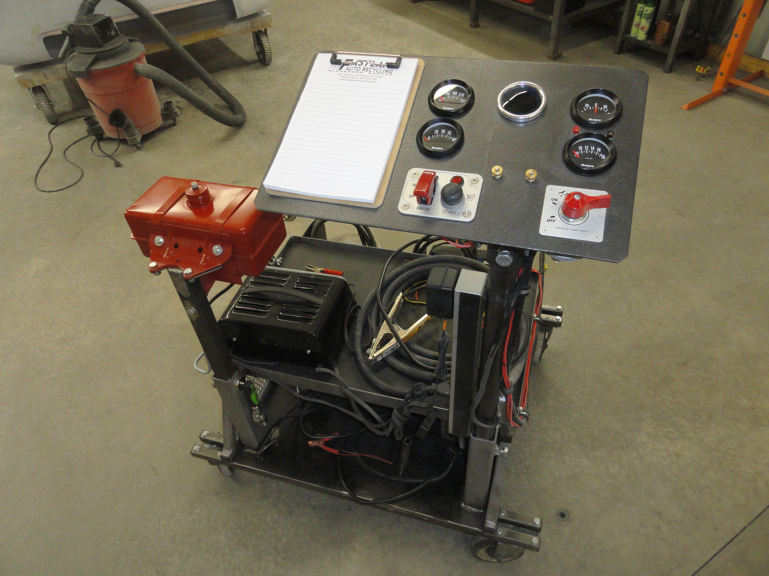
This is where I go off the reservation a little... on the original one, I felt it would be cool to have a movable console, from completely flat to about a 45 degree angle for better visibility of the gauges. I made this elaborate mechanism for adjusting the angle, then after using it, decided the one angle, 25 degrees, was just fine. Besides, the wires get in the way and I didn't want to over stretch any of them. So let's make it solid, yet the console removable during construction.
Cut the top end of your 2" by 32" mast at a 25 degree angle, then cut out a 2-1/2" by 2-1/2" square plate to weld on to the top of that angle evenly all the way around. Drill 4 number 10 holes on each corner so you can fasten the console to the mast. Once welded in place, you will have a place to attach your console, yet this makes it removable so you don't have to do all of the assembly with a mast dragging behind you! At this point, I think we have all the welding that we need to do complete the project. The structural metal work is completed, now time for the fun part!
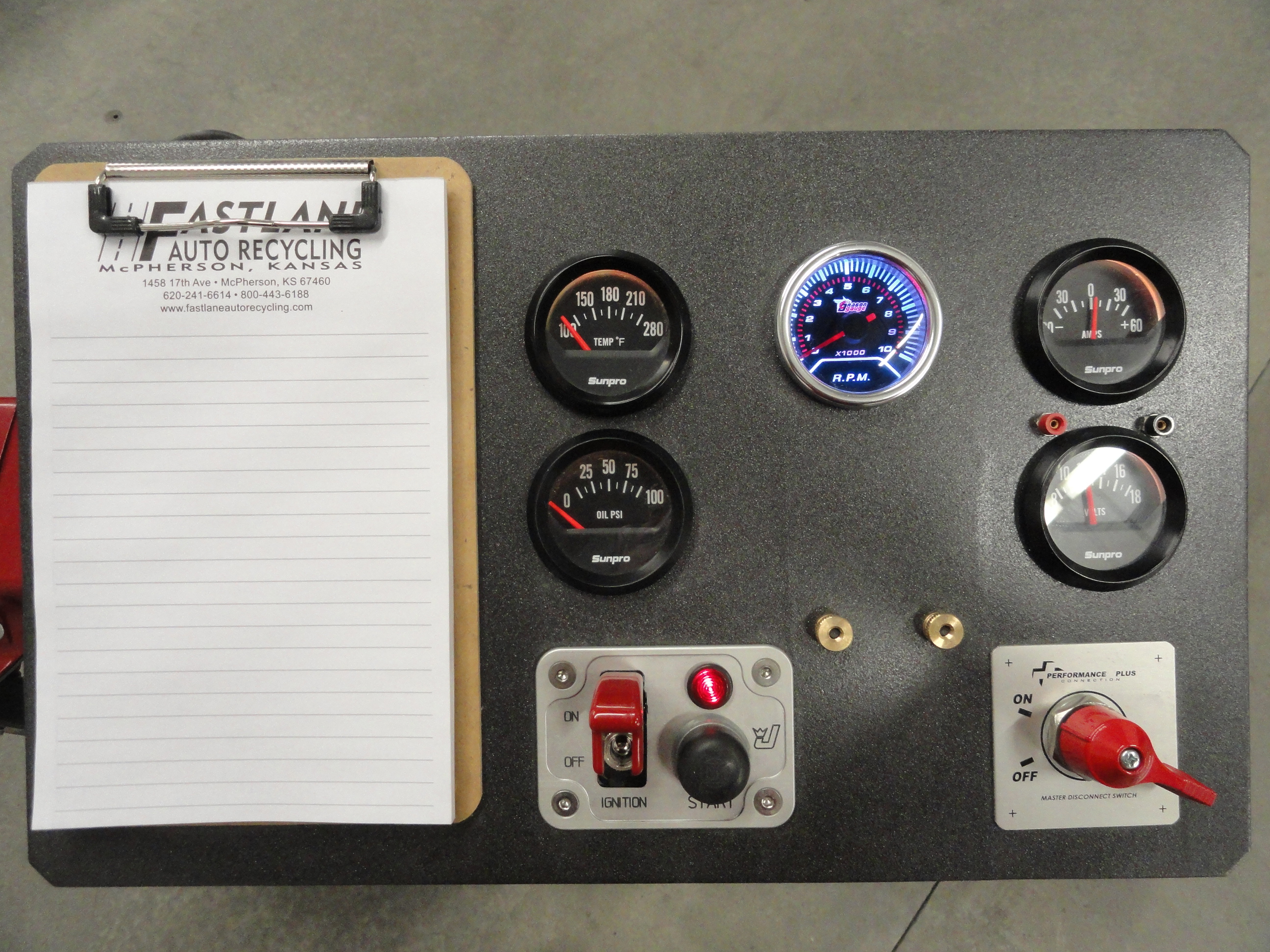
Cut yourself at console big enough to hold the gauges, test points, switches and anything else that may come up later. Really think hard about what other possible things can come up. That is why I made a notepad holder! I didn't really need it, but I wanted extra real estate in case I needed to add more gauges, switches, etc. Also remember that you can't mount anything where your 2-1/2" plate will fasten to the mast!

Emphasize careful planning here. My console measures 17" across by 10 inches using 3/32" plate. I would recommend 20 inches by 12 inches to start with. As you can see by the empty space, I made mine offset from center with space for only 1 row of gauges or switches to the right of the mast. This has to do with the profile of the Kart. I wanted the console to be inboard as much as possible. I chose to use 2 inch gauges and to cut these holes, a 2 inch hole saw worked fine. If they are a little tight, run a rasp around the holes a little to make it easier to install them. Start off by making a very clear box where your 2-1/2" mast plate connects. You can't put anything there. I used 1" as the standoff between that 2-1/2" box and the edge of the gauge, then another 1" from the edge to that edge of the gauge. I could have said just go in 4 inches, mark it, then the start of your 2-1/2" but you need to understand fully how YOU want this layed out. Once you have the holes for the gauges marked, you will want to take the switch plates off and make holes for them. Be sure to open the switch holes enough so your wires won't touch the edge of the console.
Once you have it all layed out nice, if you feel the console is a bit too big, you can cut it down to size. Drill all the holes, test the fit of the gauges and switches, mark and drill the holes for fastening to the mast. Test fit everything, then remove everything for painting. I used a textured rattle can paint to help cover the imperfections in the metal. Once very dry, go ahead and install everything again. Don't attach it to the mast so you can work more comfortably at a table.

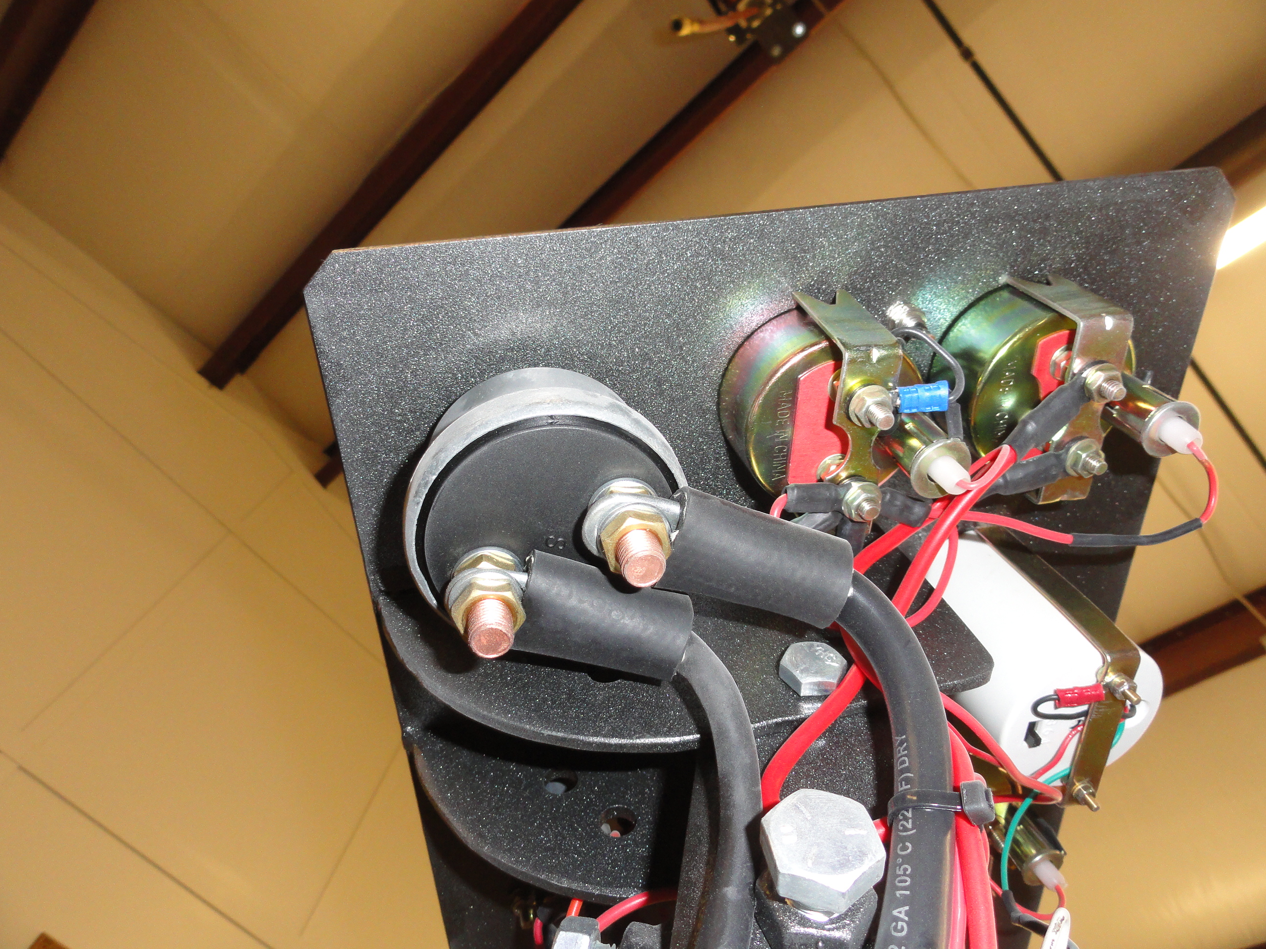
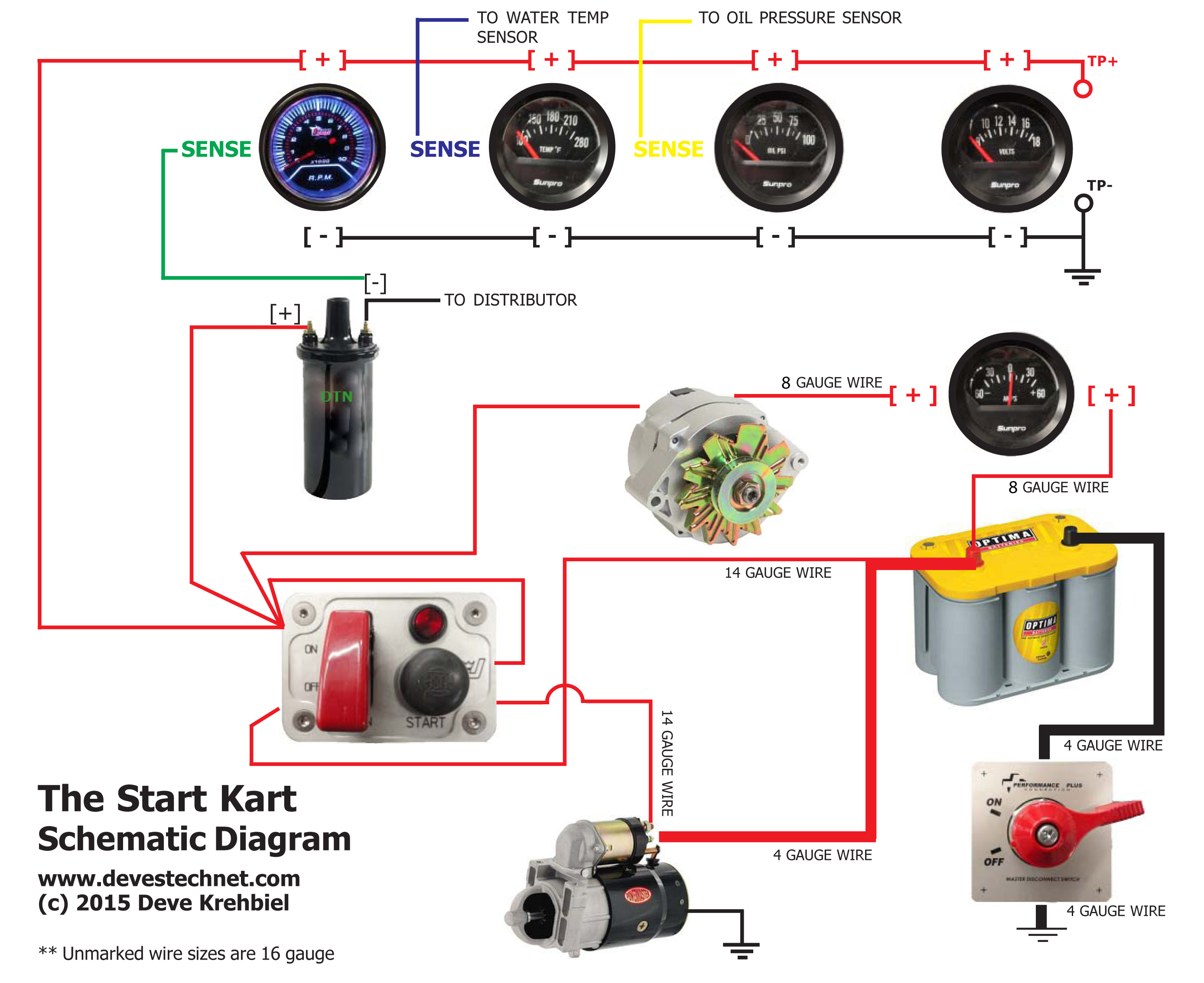
I chose electrical water temp and oil pressure gauges so I could use this Kart on a wider range of vehicles. Each gauge *all of them have a positive and a negative pole. Each gauge except for the ammeter uses the same 12v positive line and all gauges and console switches use the same negative line. I used the daisy chaining process to complete the circuit. Just NOT on the ammeter. The Ammeter will be wired separate. I simply took a short RED wire and ran it to the next closest gauge. The end of this daisy chain is at the switch console. There is no easy way to explain how to wire this, so I will let the schematic below do the talking.
I cut 20 foot lengths of each necessary wire. Make SURE you have enough of each color wire and each necessary gauge wire together in your bundle. Everything can be 16 gauge except you need to have two 8 gauge red wires in the bundle for the ammeter. This 8 gauge is NOT overkill because Alternators are getting bigger for much cheaper. The amps required may fluctuate depending on what you connect this test platform to. I even added two wires for no reason just in case I needed them later. Why you ask? Cut 17 feet of 1/2 inch heater hose. Attach about wire coat hanger or equiv gauge, a 25 foot piece of it, to the bundle. If you have ever done this before, it's very frustrating when the wires hang up and they break away prematurely, so put a hook at the end of the fish wire and twist it around the end of the bundle, then electrical tape the heck out of the end to make sure it will not break free. Feed the wire through the hose. There is not much room and some kneading and delicate prodding and lots of patience are needed here. You can't get a better insulator and better protection for your wires than heater hose. You CAN do it, so get out of your head that shortcut of cutting the hose down its length! Now you know why it's important to have all the wires in that bundle and then some! Position the wire in the hose so that you have a foot on the gauge end and two feet on the engine side.
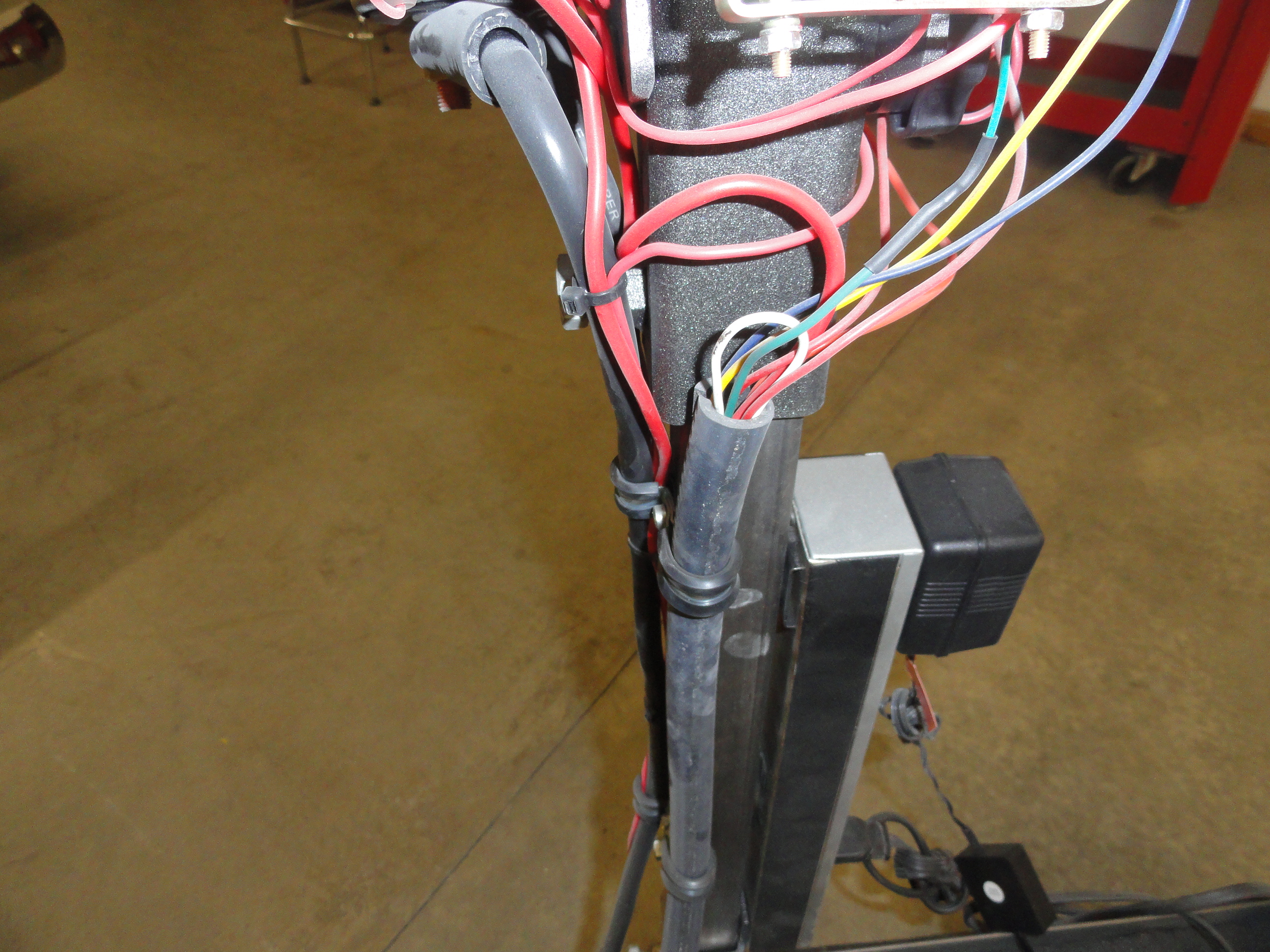

The wires (left) that you see that are not in the bundle are going from the battery to the console direct. To help you with the wires that are in the bundle, I used the colors below but you can use whatever you are happy with. This is all the wires in that bundle that are currently in use, although remember to add a few more to your bundle just in case:
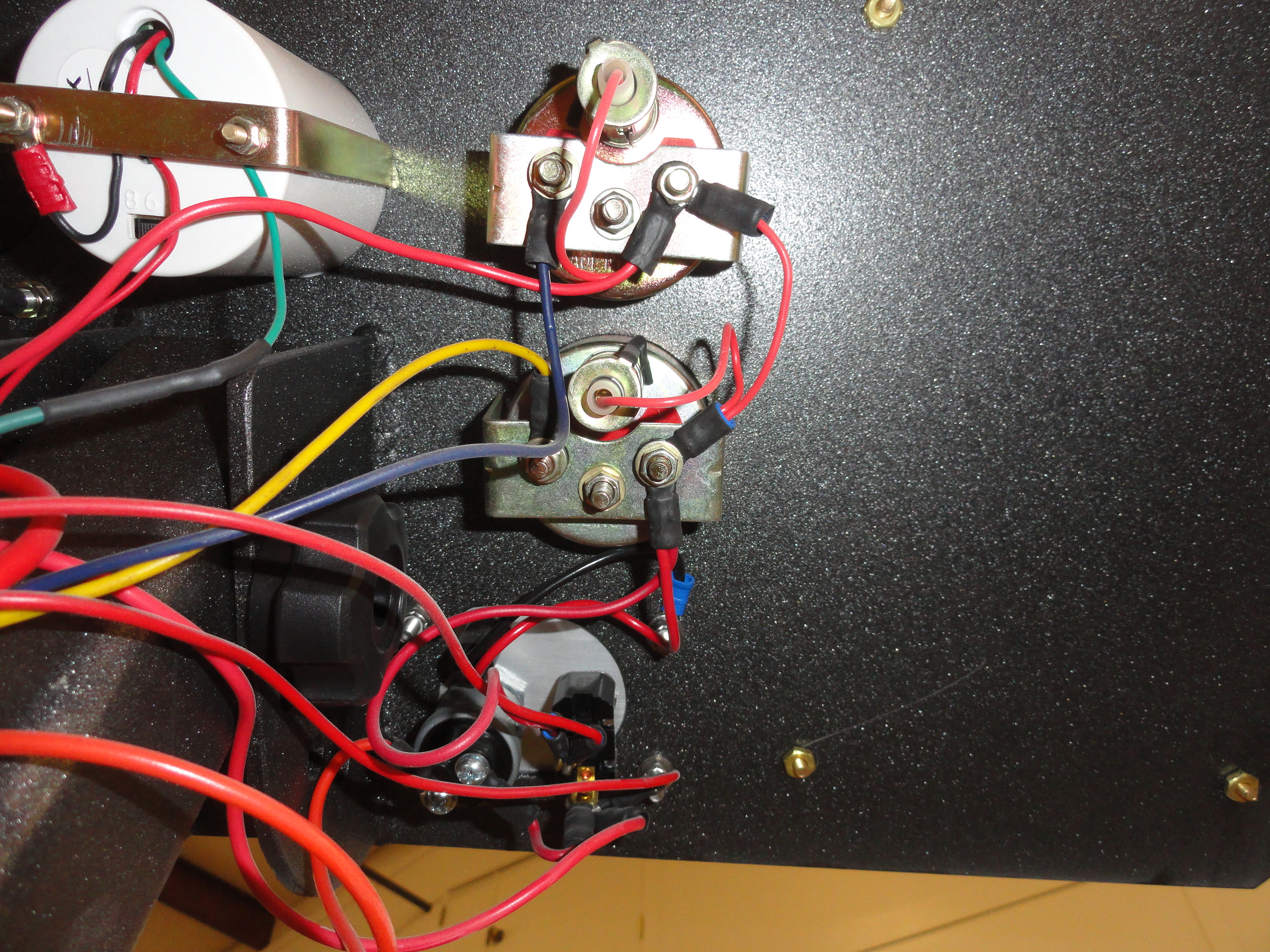
Follow the schematic and it should make sense to you. There are two smaller wires going from the positive battery terminal. They are:
1. The other 8 gauge wire to the Ammeter.
2. The power to activate all the gauges (16 gauge) to the ignition switch.
The main Positive Battery cable goes to the Main Terminal on the Starter. (use a 4 inch piece of 1/2" heater hose to insulate the end when not in use.
The Negative Battery cable goes to the cutoff switch on the console, then down to a post on the side of the Kart. This gives the Kart the same potential
as the engines systems making it safer. On the Kart near the Negative post on the Battery I put the negative battery cable that will clamp to a good
grounding spot on the engine or chassis.
To properly connect the Alternator, the main post has the 8 gauge wire on it, but needs a (F) field wire jumpered to it to give it power. Use a piece of 12 gauge for that. The (F) and (R) I am talking about is the two terminals on the Alternator that are smaller. So small jumper from (F) to the main terminal. (R) is connected to your long bundle to the on side of the ignition switch. Mark everything so you don't forget the next time you use the Kart!
Aside from the gas tank, we need fuel line, a fuel filter, and a good shutoff, I made mine out of hard line to the fuel filter as shown. I keep a bucket on the Kart and the hose rolled up inside of it to connect to the fuel pump. You are bound to have it leak out a bit when detaching the fuel pump line so the bucket comes in handy. I like to keep my gas tank a little higher than the fuel pump so that's why I built the raising and lowering ability into the system. Not real sure that feature is needed much, but it's there anyway!
More Pics available on the Site Archive Page!
Join in on the conversation at: The Think Tank Shop Discussion