

Deve's Technical Network
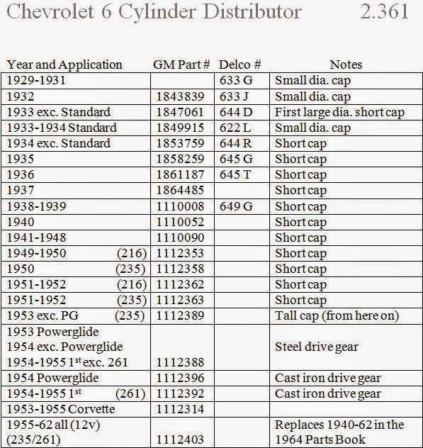
1947-1955 1st Chevy Trucks
216/235/261 Engine Solutions & More
The Youtube video is provided for those of you who do better watching someone else. As usual with my video's, the Kit is the star of the show. My
Youtube channel has an ever-growing number of videos, so check back from time to time. The HEI Installation one is here:
216/235/261 HEI Installation Video
The cost of the kit is $184.50 plus $15.50 Postal Priority Shipping. Also see "Distributor Modification Services Available" below. I am doing this to provide kits for my friends. If you are not 100% satisfied with your system, I will return every cent as long as you return the kit in perfect shape (internal packaging, boxes, etc). Send Certified Check, Money Order or Cash to: Deve Krehbiel * PO Box 676 * Hesston, KS 67062. Or use the PayPal Button below. Be sure I get a return address! As important as getting paid is for you to specify your Distributors model number. Please read this document before sending any money. I will also work with you on obtaining specific components of this kit. The idea is for you to be happy! Email deve@speedprint.com for any questions you may have.
Once you have gone to electronic ignition you won't have to ask why you need it. What is even better about this kit than Pertronix for example is, it is a real GM HEI system. Pertronix is an alternative to points, while the GM HEI controls not only the points trigger, but also controls the dwell and timing based on RPM. It has its own current control limiter that keeps the current below 6 amps while providing for a much hotter and much more precise spark. This is GM's early version of the modern Electronic Control Module. While points systems have withstood the test of time, they have to be adjusted or replaced every 5000 miles or so while HEI is maintenance free. Especially now, 50+ years later, the vintage distributors are getting worn causing points to fire erratically and dwell to be less stable. This modification takes the responsibility of timing and dwell and moves it over to the GM HEI module.
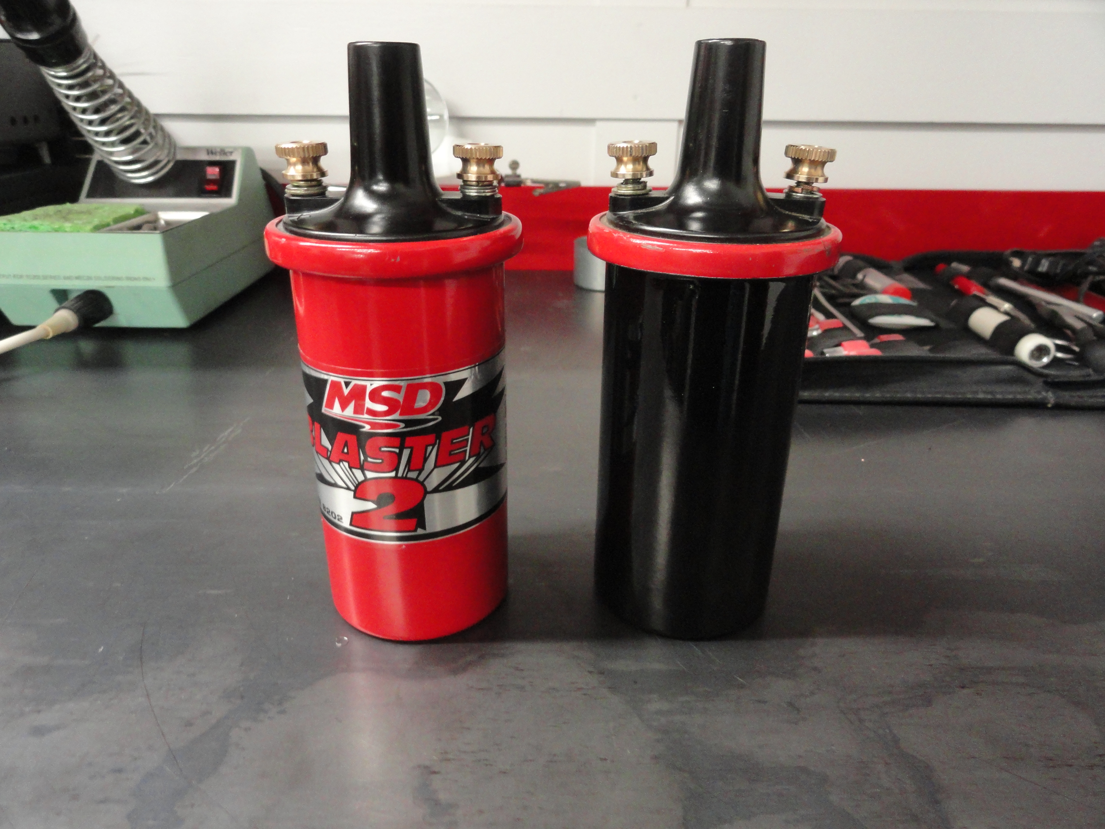
The reason we do not include everything is because of the fluctuating vendor pricing and they are not 100% necessary to get your new HEI Ignition System running. We highly recommend purchasing these items however. It will ensure perfectly smooth ignition performance. In the case of the plug wires, it is just safer to use approved wires. This kit only works with 12 volt systems. Do NOT put the high performance coil on without using approved plug wires!
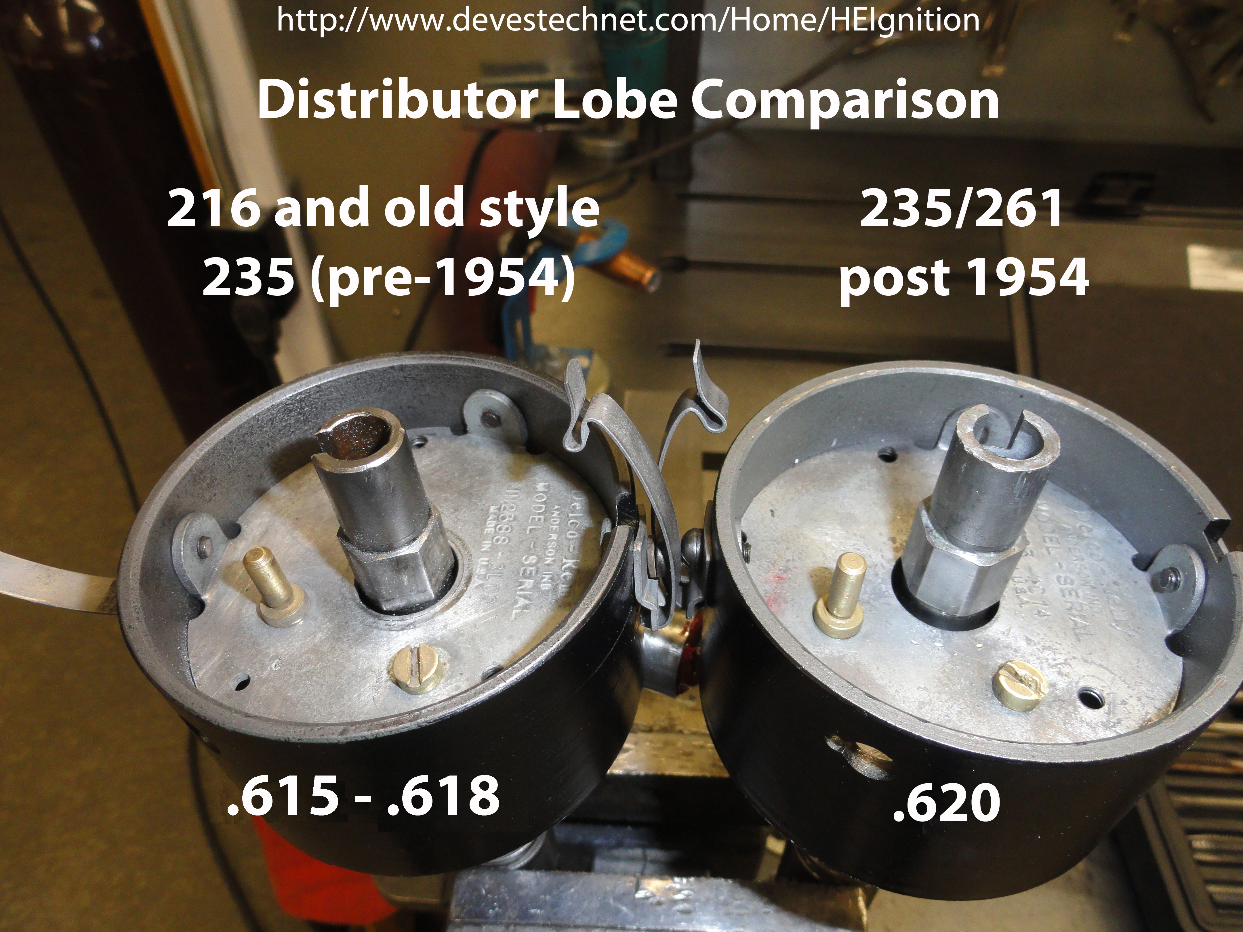
GM made two different types of lobe contact areas depending on the year of your Distributor. Most of us enthusiasts purchased our vehicles from previous owners and we are not 100% certain that things have not been replaced along the way. To ensure you get the proper reluctor for your distributor, remove the cap and with a flashlight look carefully at the mounting surface where the points and condenser are mounted. Write down the stock number of the distributor and tell us what it is. The number starts with 111xxxx. Also take a look at the lobes and compare them to the picture on the left. Be sure to specify this when ordering the kit! Remember, we can only upgrade a tall cap distributor. If you need a tall cap model, email deve@speedprint.com. We will get you one.
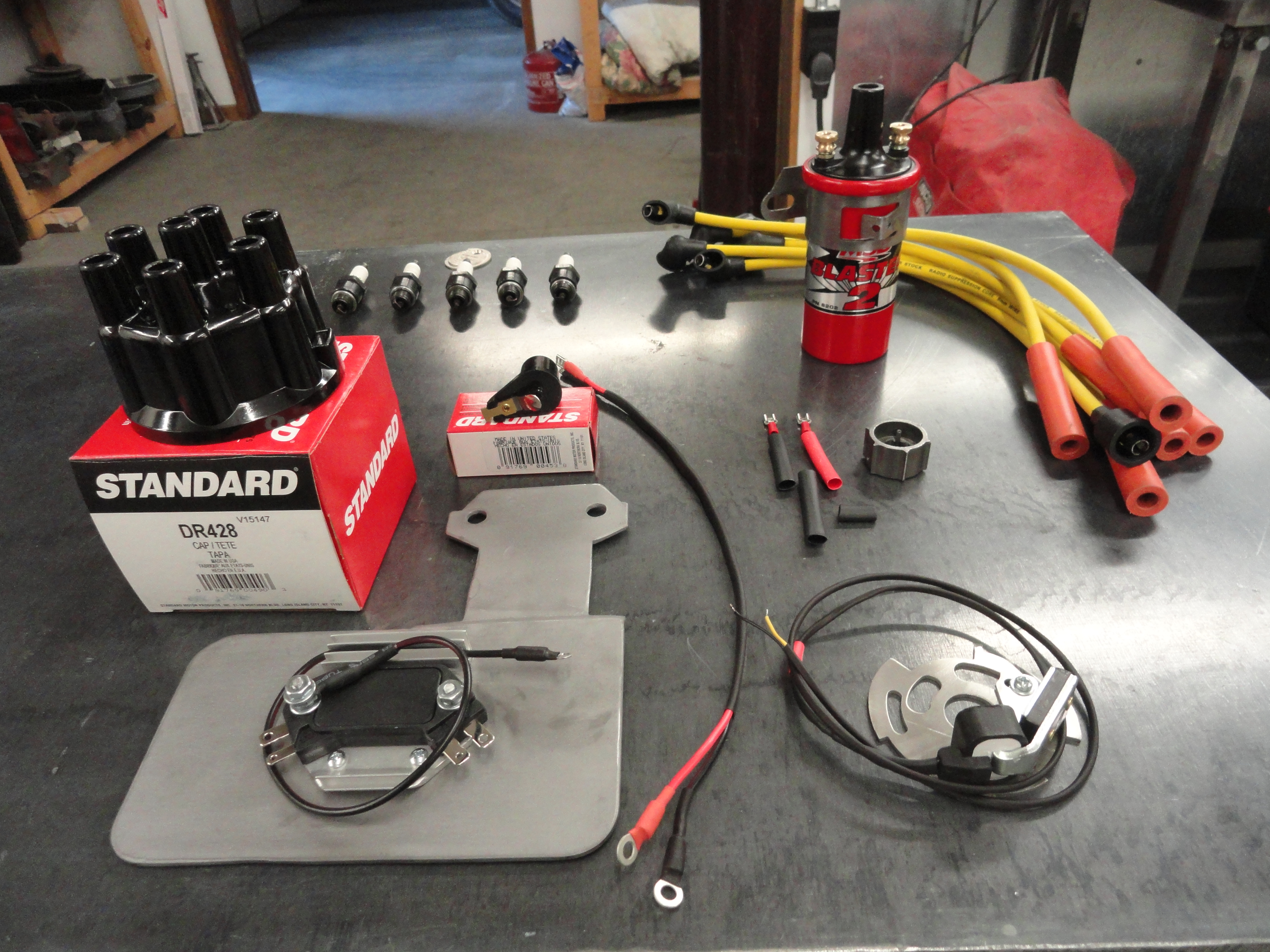
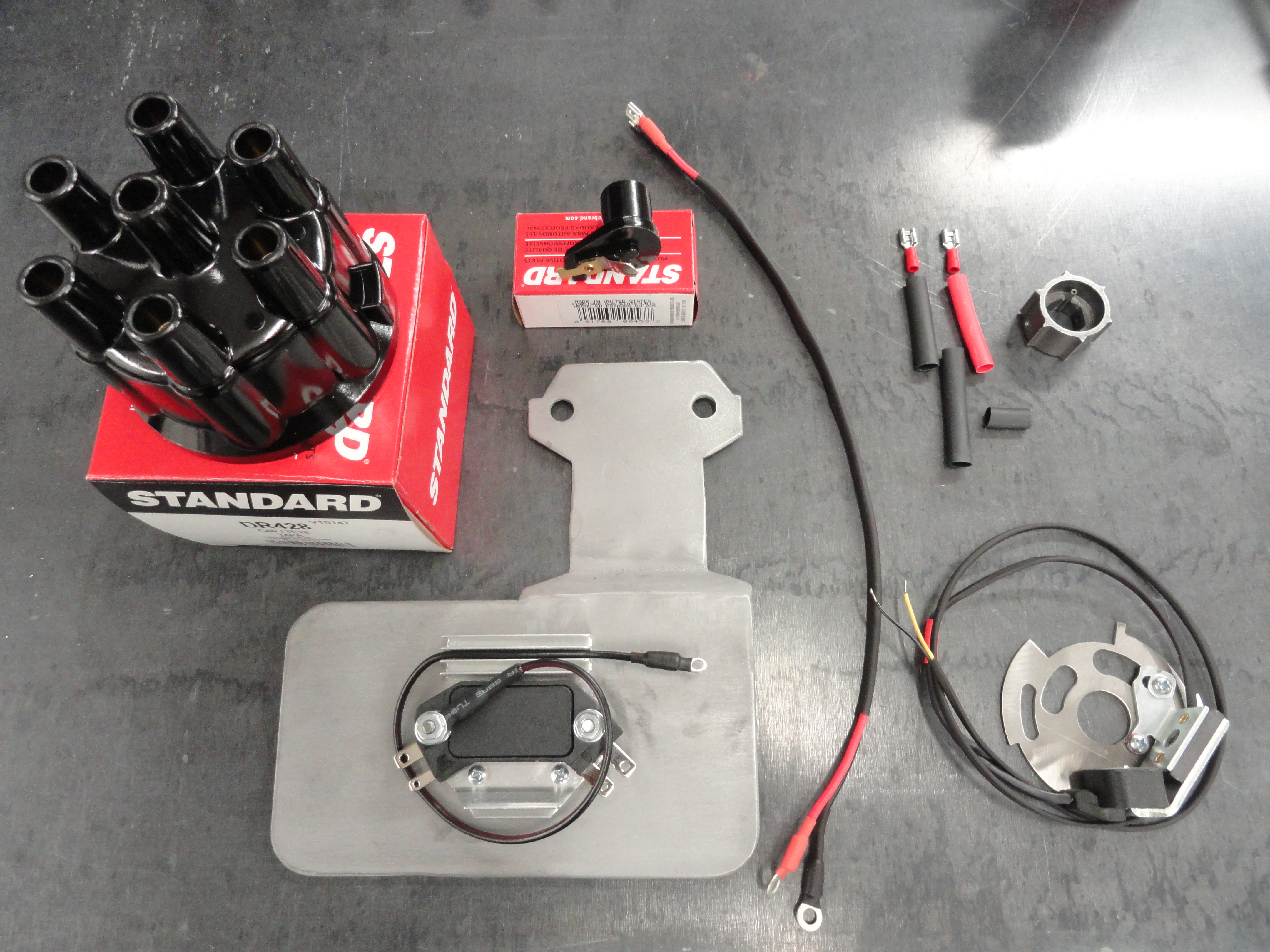
In your HEI Kit you should find the following items. The wires are the length required to work with the included HEI mounting plate. It is okay to add length to
the wires but ensure the same gauge is used. Remember length adds resistance which isn't a good thing.

To do this with any accuracy, we need to remove the Distributor. Please follow these instructions carefully! Especially if you have never done this before, or are not very
comfortable with doing it. Since the Distributor Gear is what turns the Oil Pump, you WILL destroy your engine if you do not re-install it properly! The picture
on the left shows the distributor all the way down in its proper position while the one on the right is showing what happens when you pull it out. You want to write
down both orientations so you can more easily install the distributor when the modification is complete. It is best to take a picture of the entire side of the engine so
you can see where your plug wires go, and then closeups of the rotor orientation before and after removal as well as pictures of the orientation of the distributor housing
as it sits in the block.

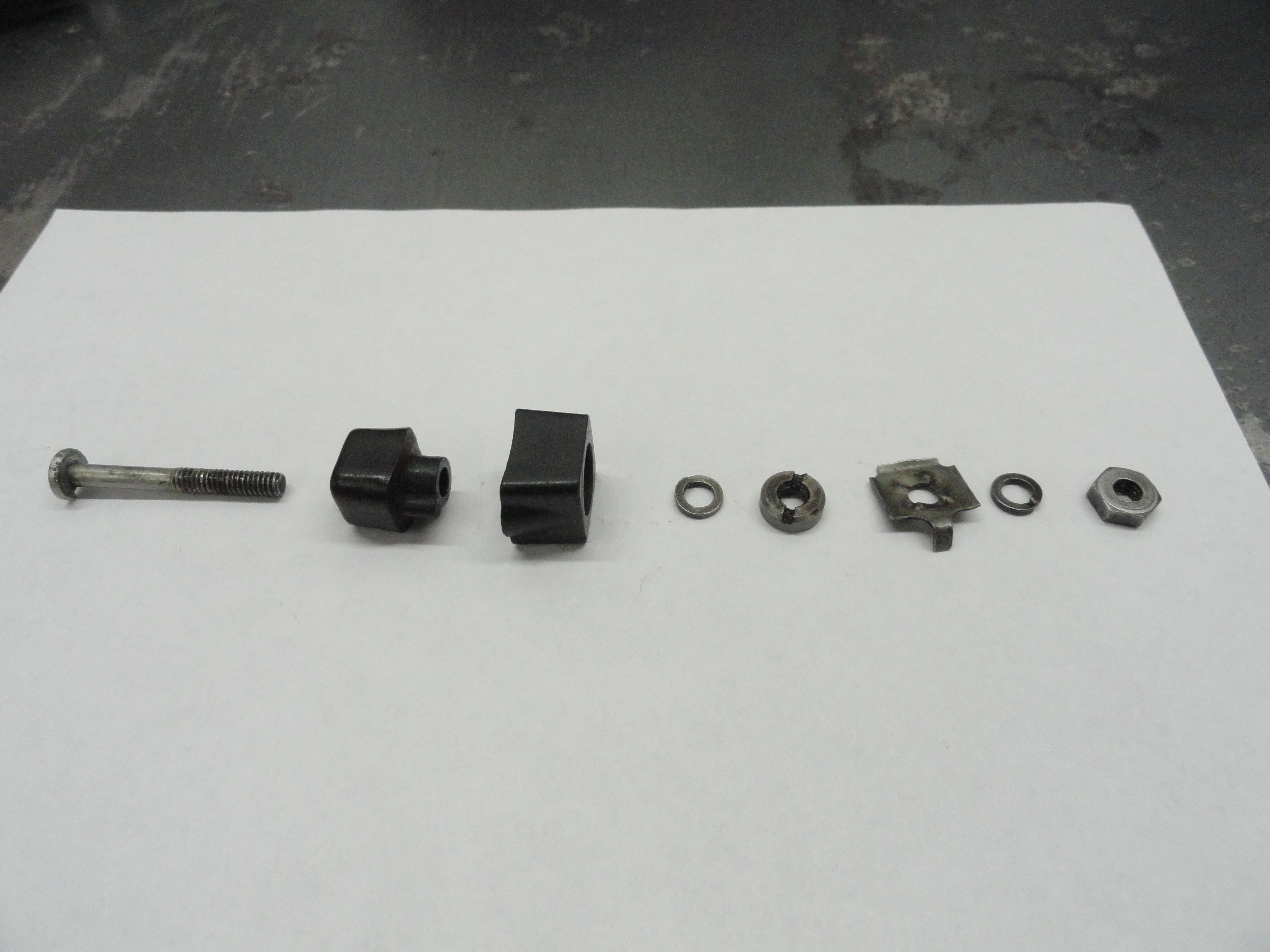
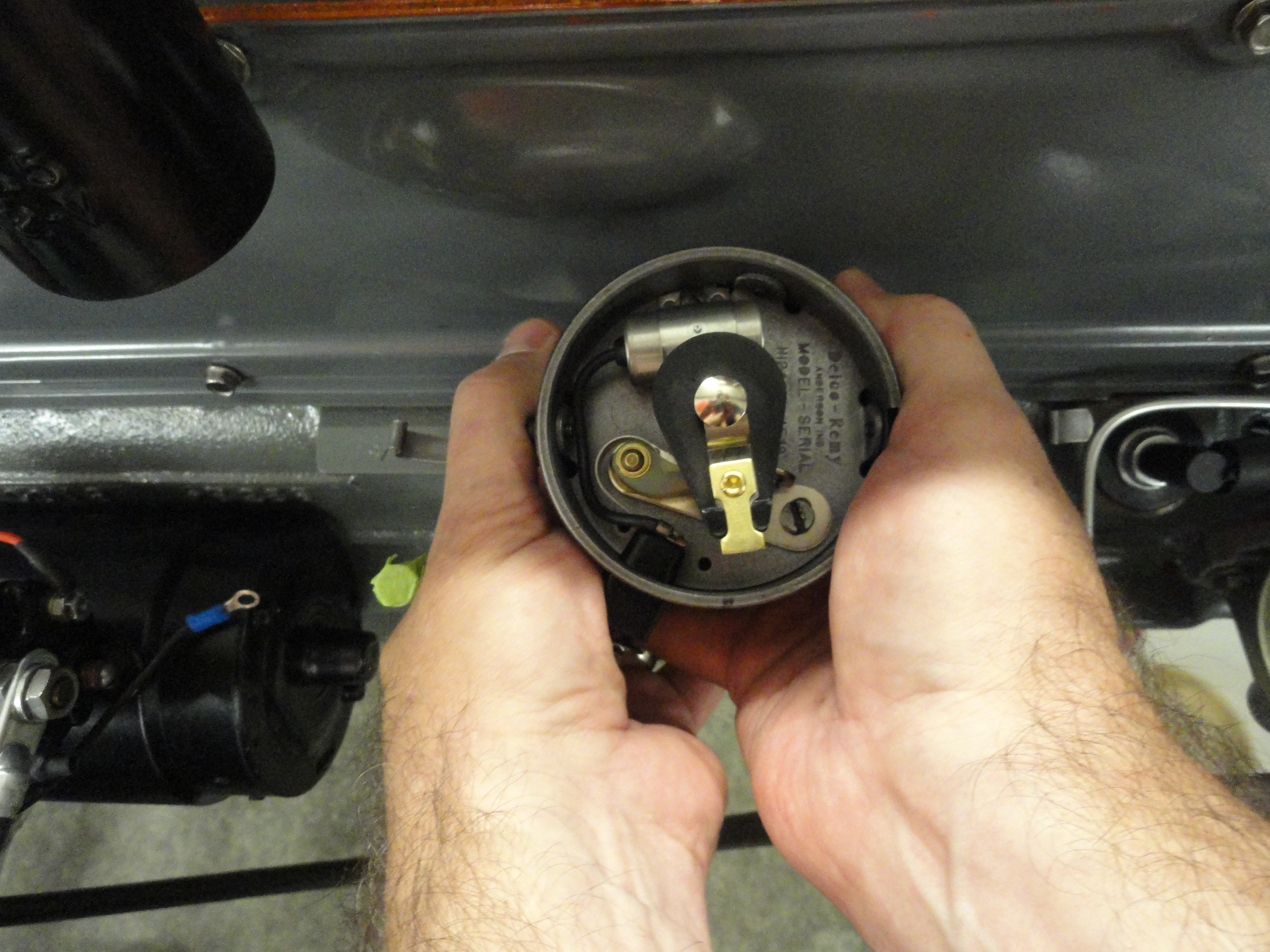
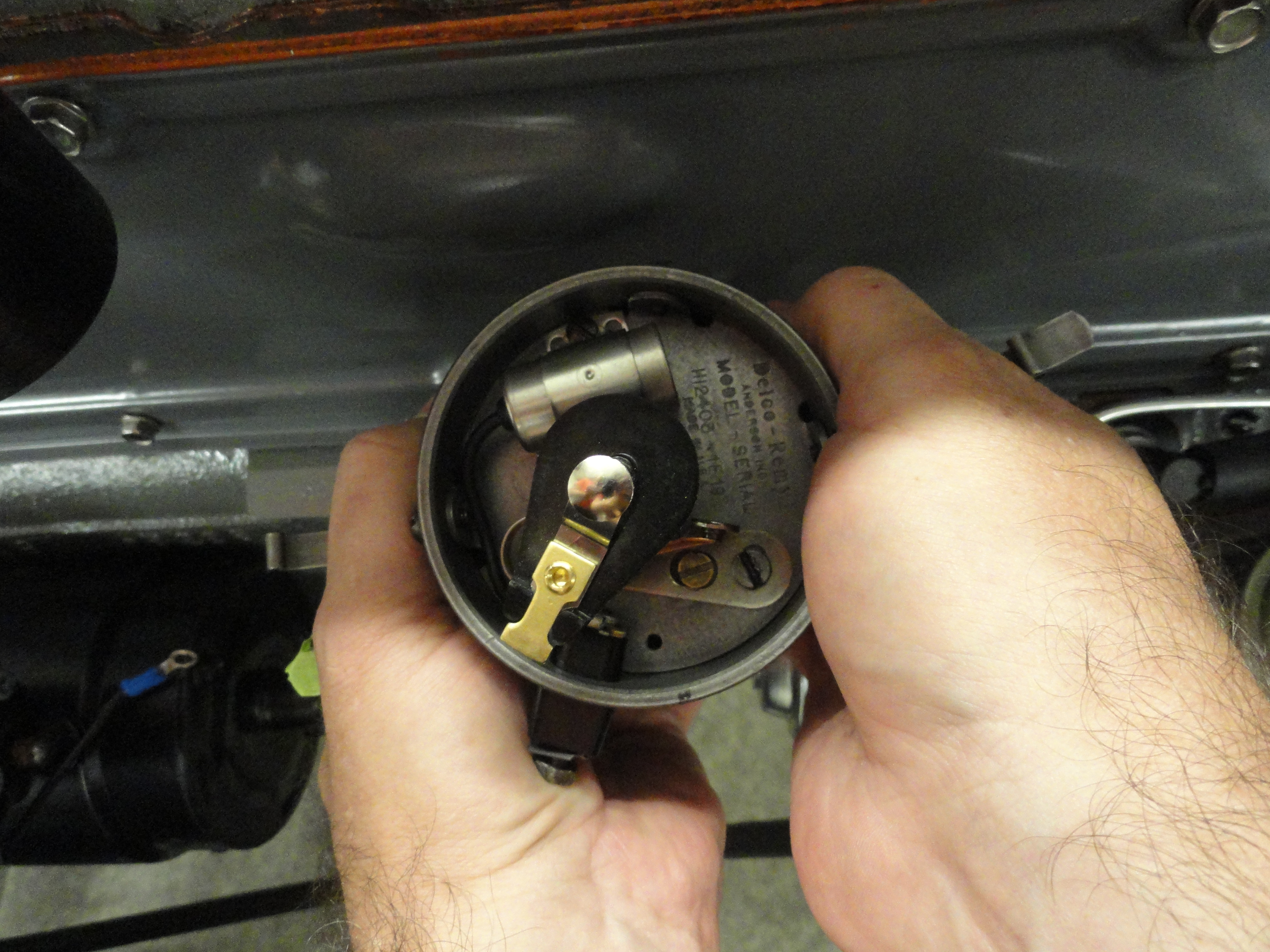
Remove the Points, Condenser and Rotor. In doing so, you will also want to remove the long screw that goes from inside the distributor to outside the distributor. This is the contact system for the wire that goes to the negative side of the coil. The two plastic pieces that the screw runs through will be your conduit for the new system. This helps to make everything look stock. You will want to seal those two pieces together (and to the distributor housing) so they cannot come apart. This will have no effect on operation of any system, but will ensure a nice wire conduit. The wires are sized to go through this conduit. Save the screw and all associated hardware. To get to that rounded nut with slots on each side of the screw, I just squirt it with WD40 and use a very small screwdriver on one of the slots. So far, it has worked every time. Clean the two pieces thoroughly to remove the WD40 or any other residue then put a good coat of Permatex Gasket Maker on the two pieces and put them back on the distributor housing exactly as they came out. The outside piece is concave to form to the round of the distributor housing and the inside piece is oriented so that the screw slot goes down. Clamp them in place. You can use the screw that went all the way through only backwards to accomplish this. Come back the next day to install your new system. Do not get any sealer in the through-hole. If you do, use a paper clip or something to clean it out to the same size it was before. Use the long screw as a clamp while the Permatex sets. Put the nut on the inside and the head on the outside.
If you want to keep working while the sealer is setting up, install the Distributor to HEI Module ground wire. The perfect place for this even if it is hard to get to, is the small screw at the back of the distributor that holds the points and condenser plate in place. There are three screws that do this, but two of them are used for the cap clips. Install the small terminal end of the Black ground wire that comes in your kit to the Distributor connection, and the large terminal end to the longer mounting screw on the HEI Module. This grounding wire is insurance that we have a good ground throughout the system.
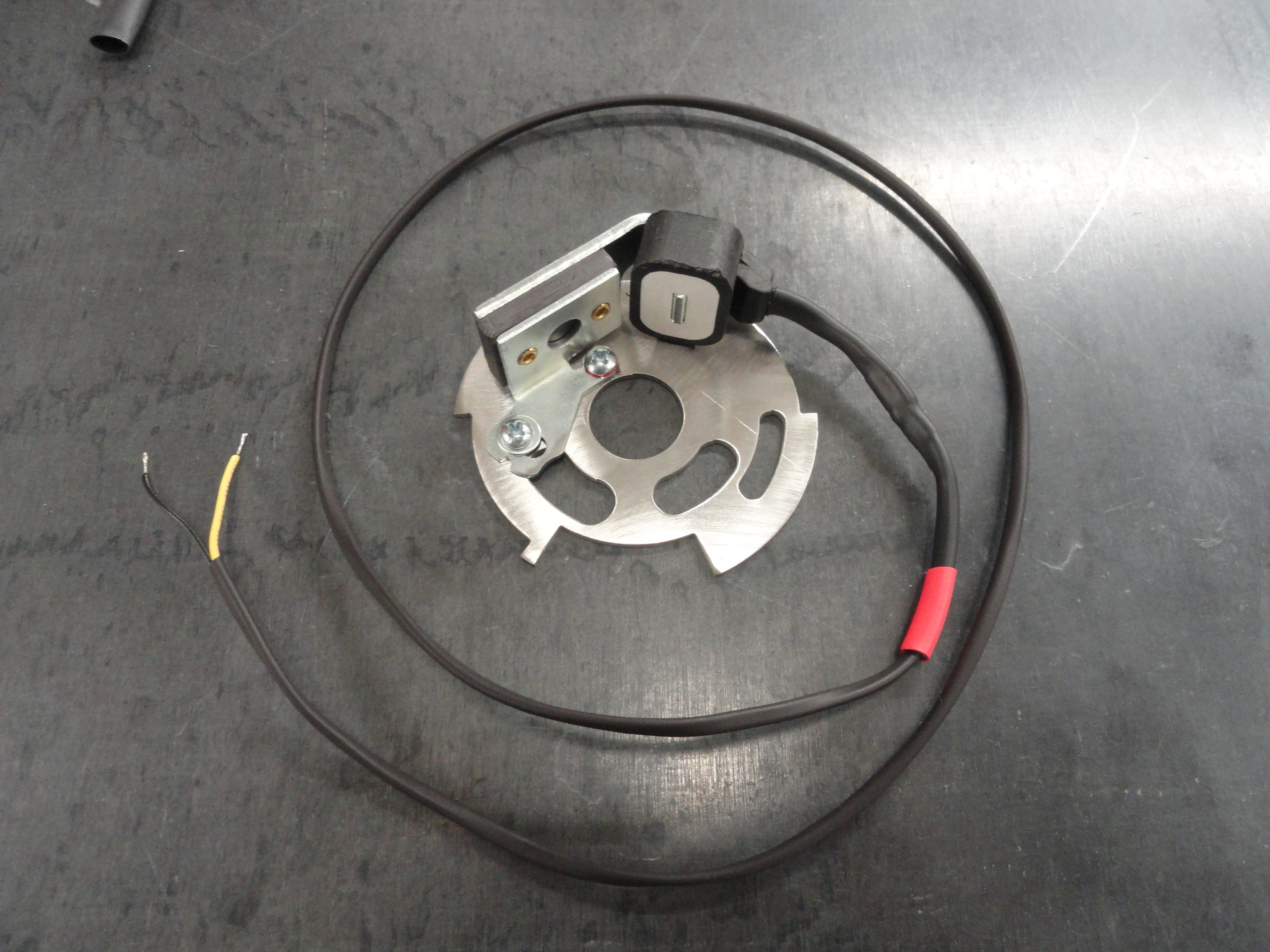
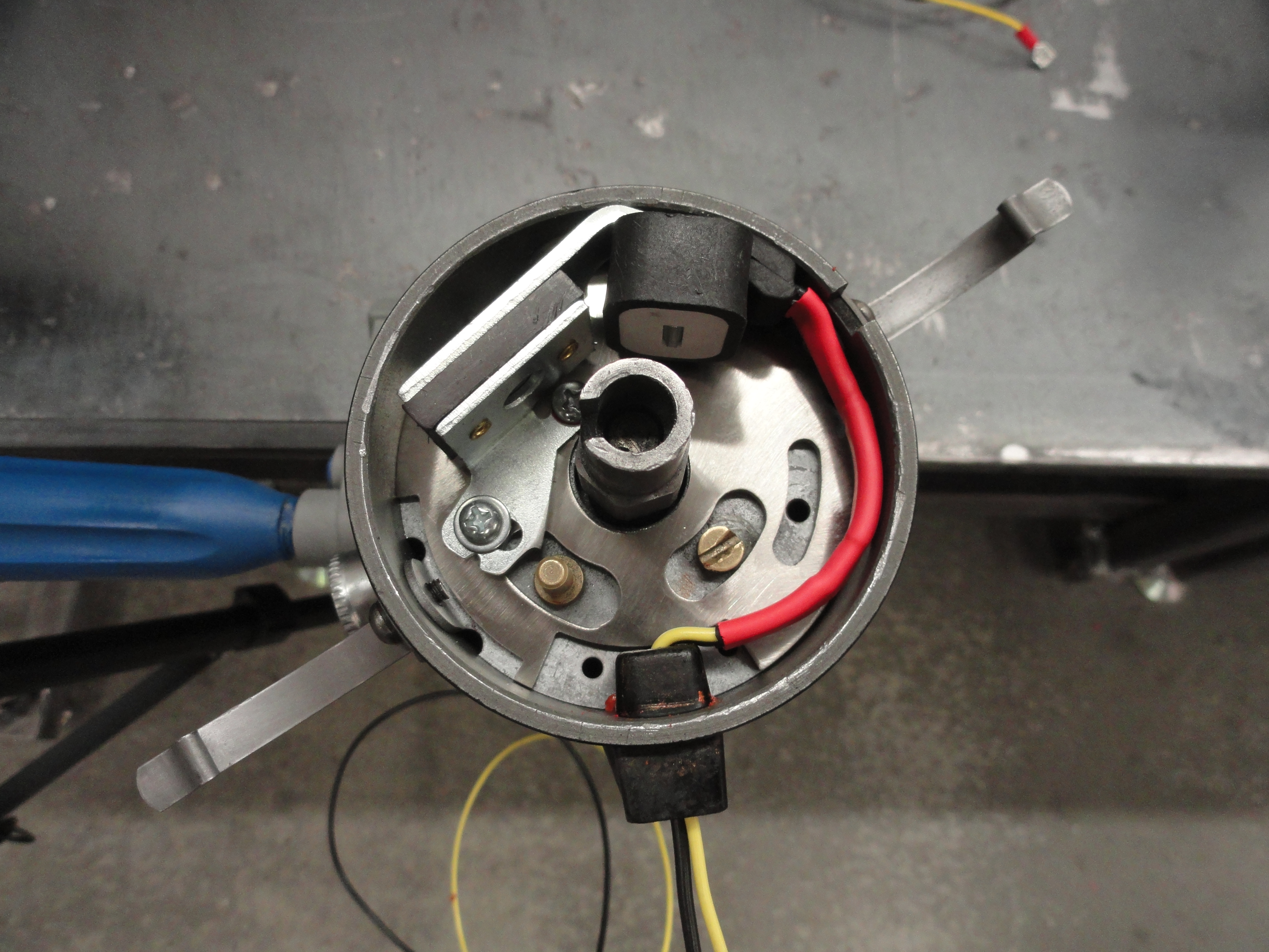
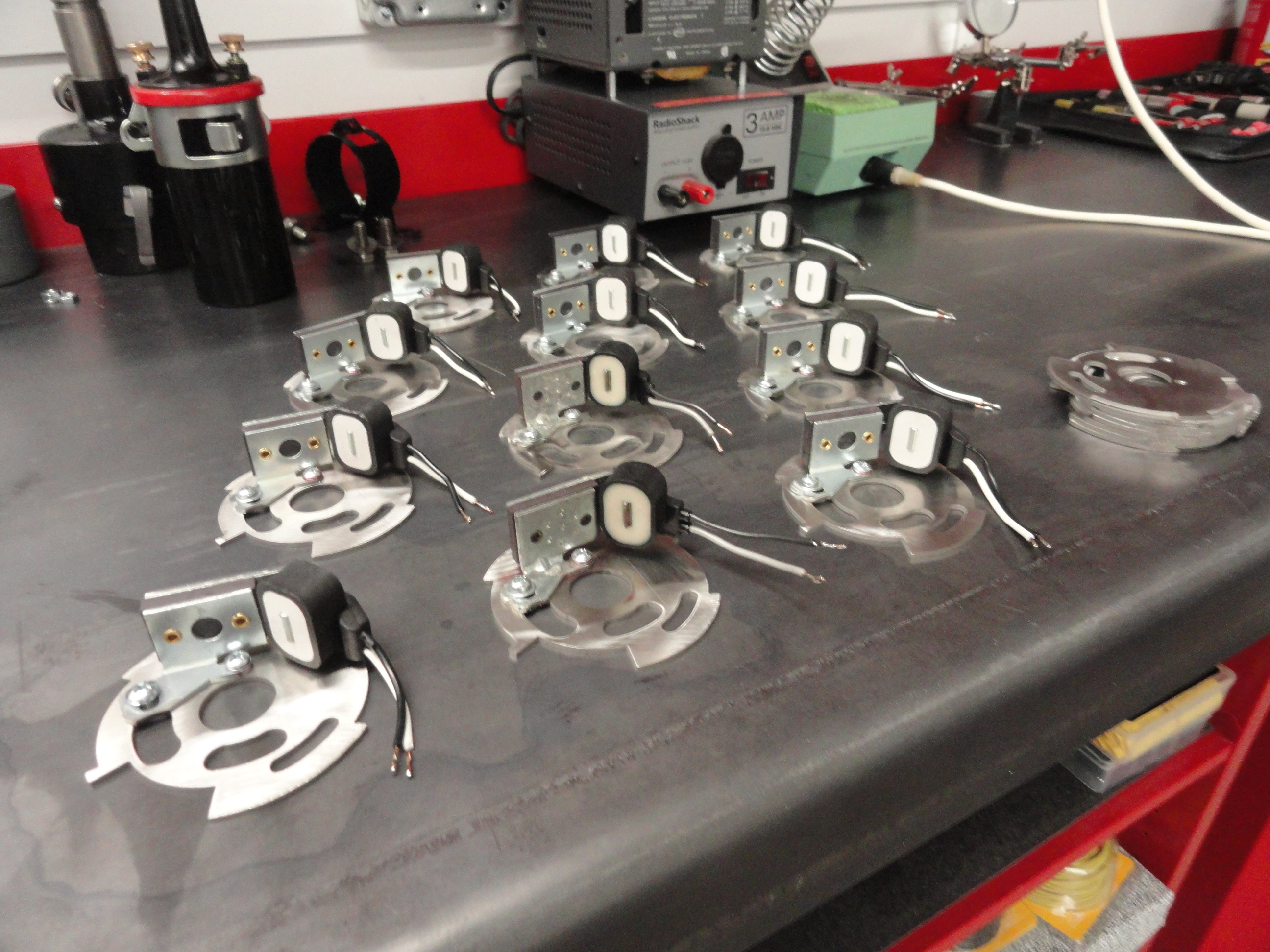
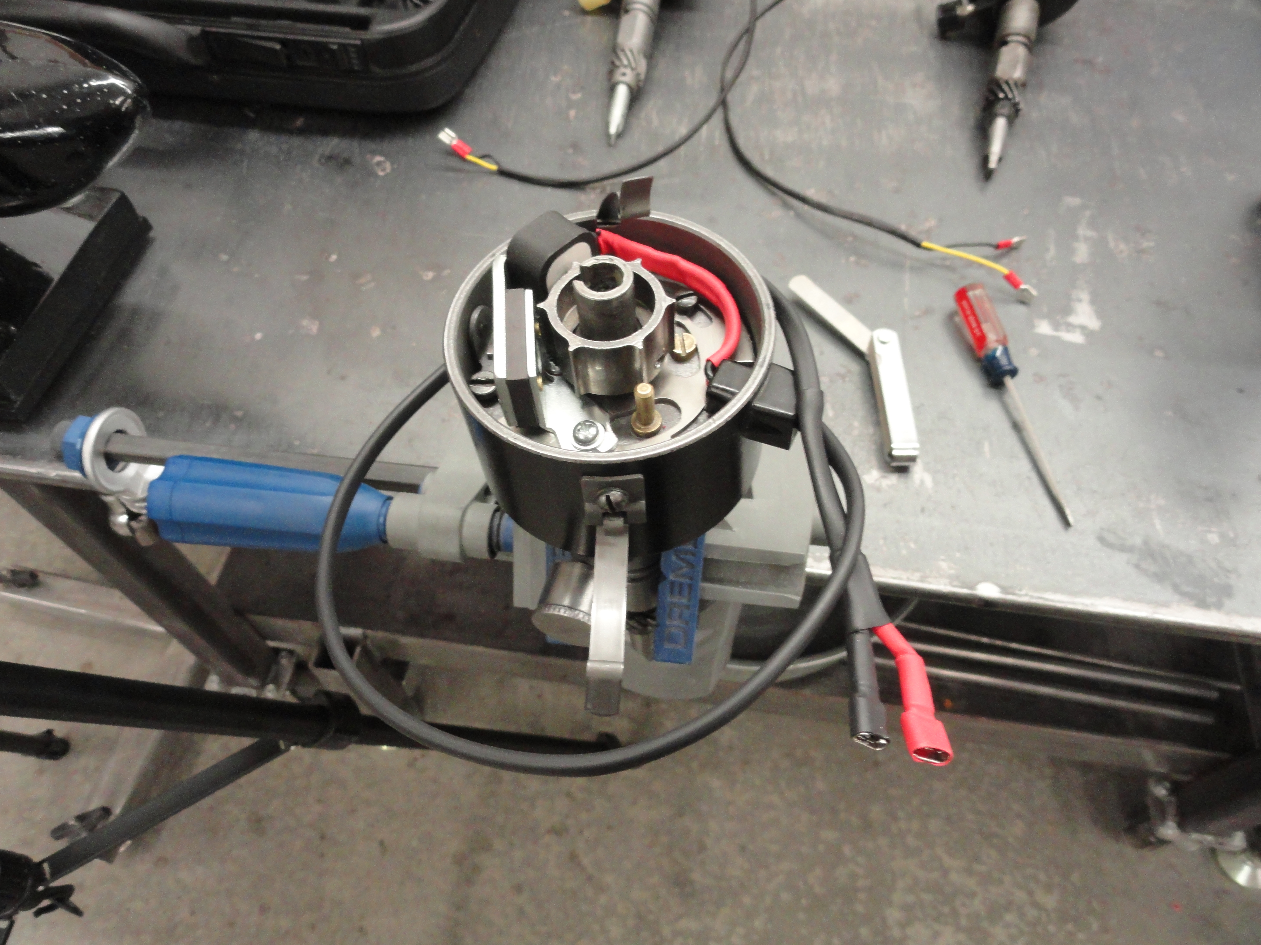
Install the Reluctor Pickup with Adapter Plate The reluctor pickup assembly only goes in one way. The idea is to drop it down over the points tower and cam screw while having the points mounting screw visible. You WILL have to adjust the cam screw to go into the adapter plates hole. Just turn the screw until everything aligns. Once it is in place, turn it so that the mounting screw and everything else is in the middle of the elongated holes. If your cam screw is not in the middle when everything else is, turn the cam screw a little less than 180 degrees and everything should be in the middle. Using your existing points and condenser hold-down screws, tighten it down securely. Use the smaller headed screw on the old points hold-down and the larger head on the old condenser hold-down. Thread the wires through the wire conduit hole until it stops due to the thicker heat shrink not allowing it to go further. This enables a nice tight fit inside. Knead the wires in place inside the distributor to the outside edge so they do not interfere with operation. Your new adapter plate is made out of 11 gauge stainless steel and will last a lifetime.
Thread the two wires through the wire conduit (it's tight but very do-able), then thread the long heat shrink that is included so that it is tight up against the wire conduit. With a heat gun, shrink this long tube so that it keeps the wires tight both inside and out. Pull on the wires at the end while pushing on the tubing to ensure a very tight fit. Heat guns are about $15 and very useful. To differentiate the two wires, I have included a piece of red tubing and two black ones. Place one black one over the entire wire assembly and slide it down and out of the way. Put the red one on the yellow wire, then crimp the terminal on. The wire has been tinned so that you have a stronger crimp. Shrink the red one so that it's even with the end of the spade terminal. Do the same with the black wire with black shrink tubing. Lastly, slide the other black one up to meet the connectors just to seal things off. Watch the video to make things clearer.
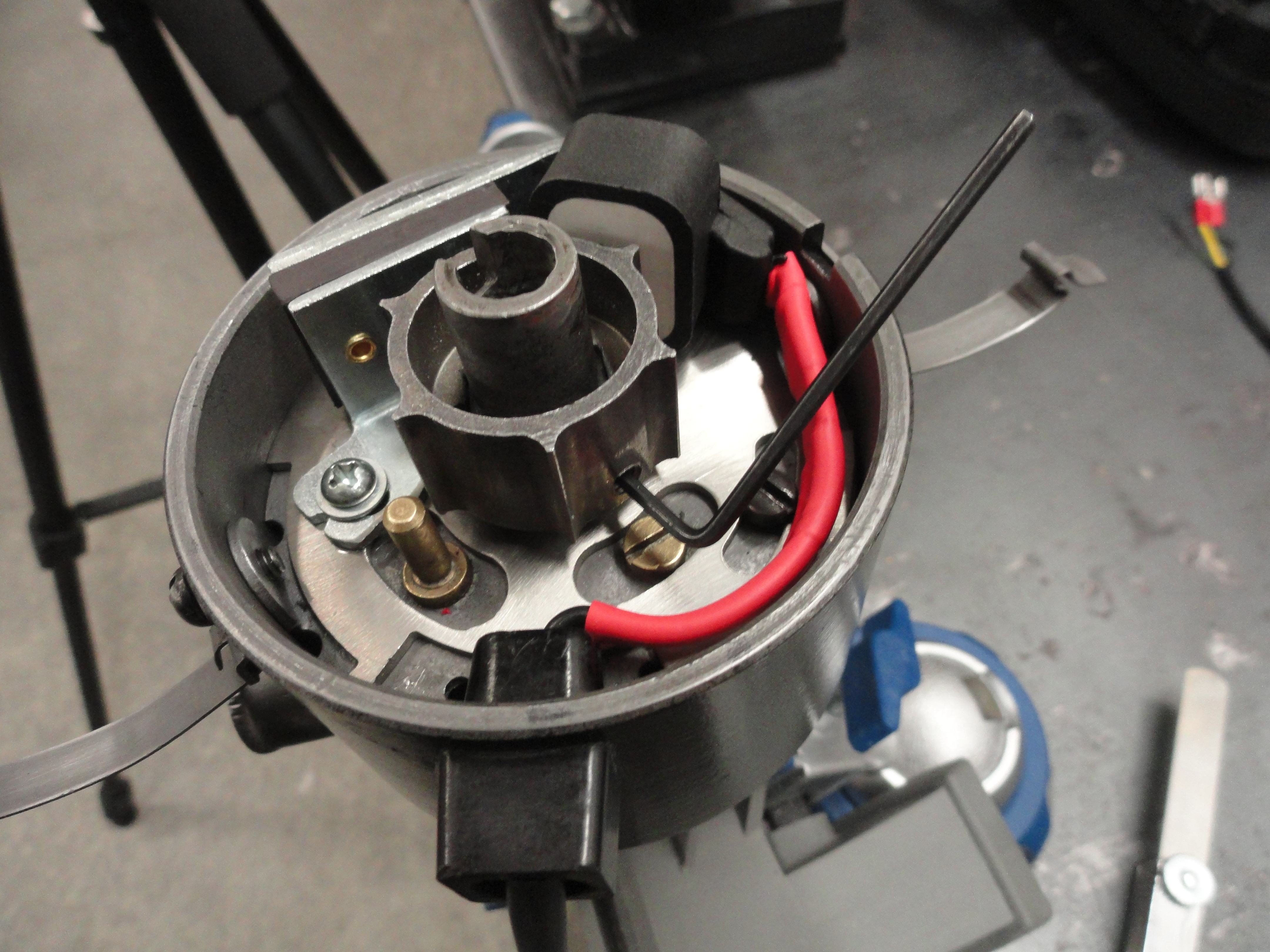
Install the Reluctor Slide the Reluctor over the lobes in the center with the concave part facing up. Slide it down to where it makes contact with the adapter mounting plate, then lift it up about 1/16th of an inch just so that it doesn't rub on the mounting surface. If it's a bit too loose, lift it out and try it on another side of the lobes until it is as tight as it gets before the set screws. There should be no contact with moving parts at this point. Tighten the two set screws securely. Use medium Loc-Tite just for peace of mind. The Reluctor is one of the integral parts of the mod. Because the 6 lobes are exactly the same distance apart from each other, there will never be a situation where wear will cause inaccuracies. This Reluctor is especially useful for our purposes because the rotor will drop right down where it belongs without interference. Also worth noting, this system does not put a small spark to a breaker points system, rather a magnet and a magnetic field causes a very clean trigger each time the Reluctor passes the Reluctor Pickup. No voltage is required because it makes its own!
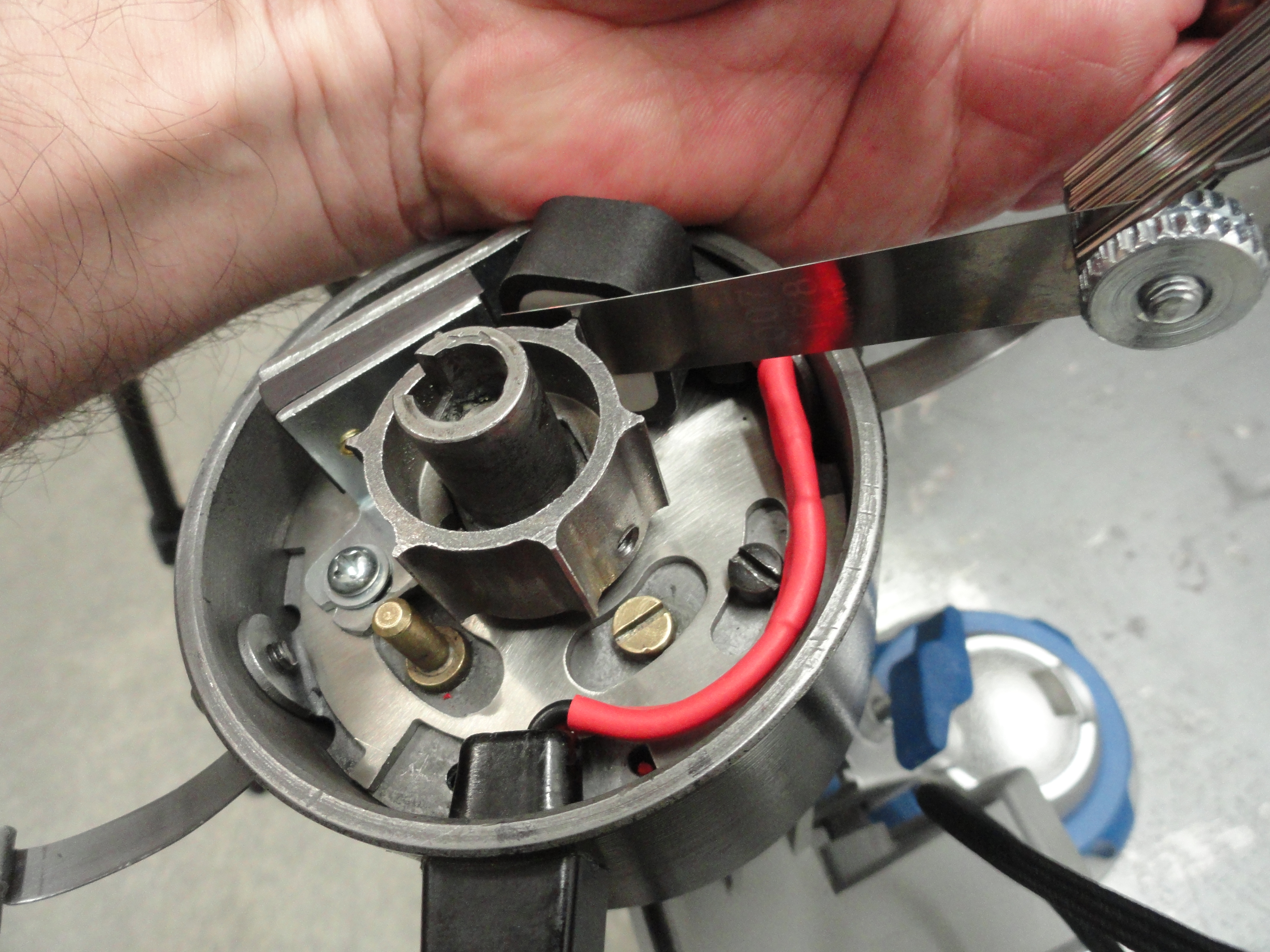
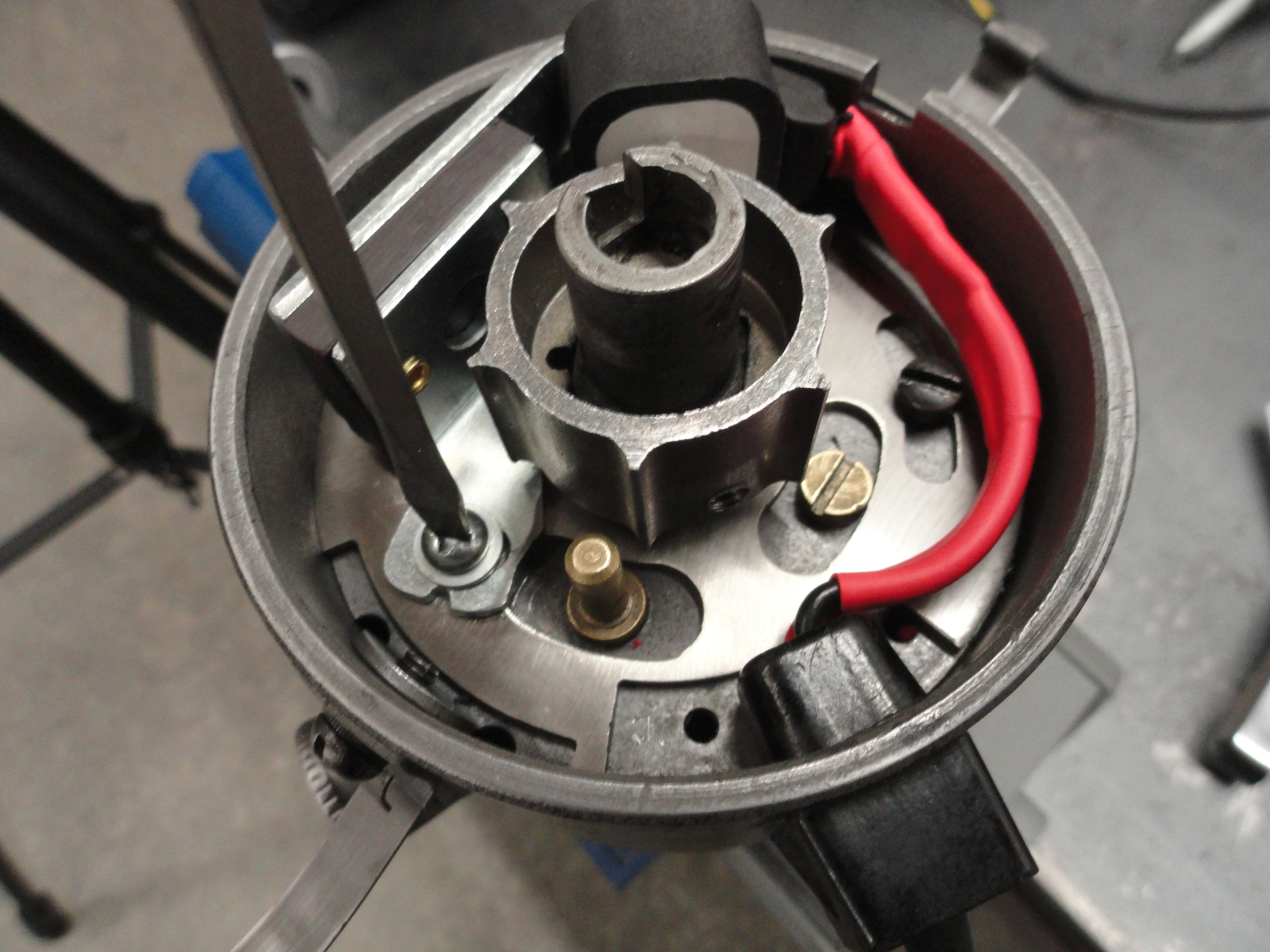
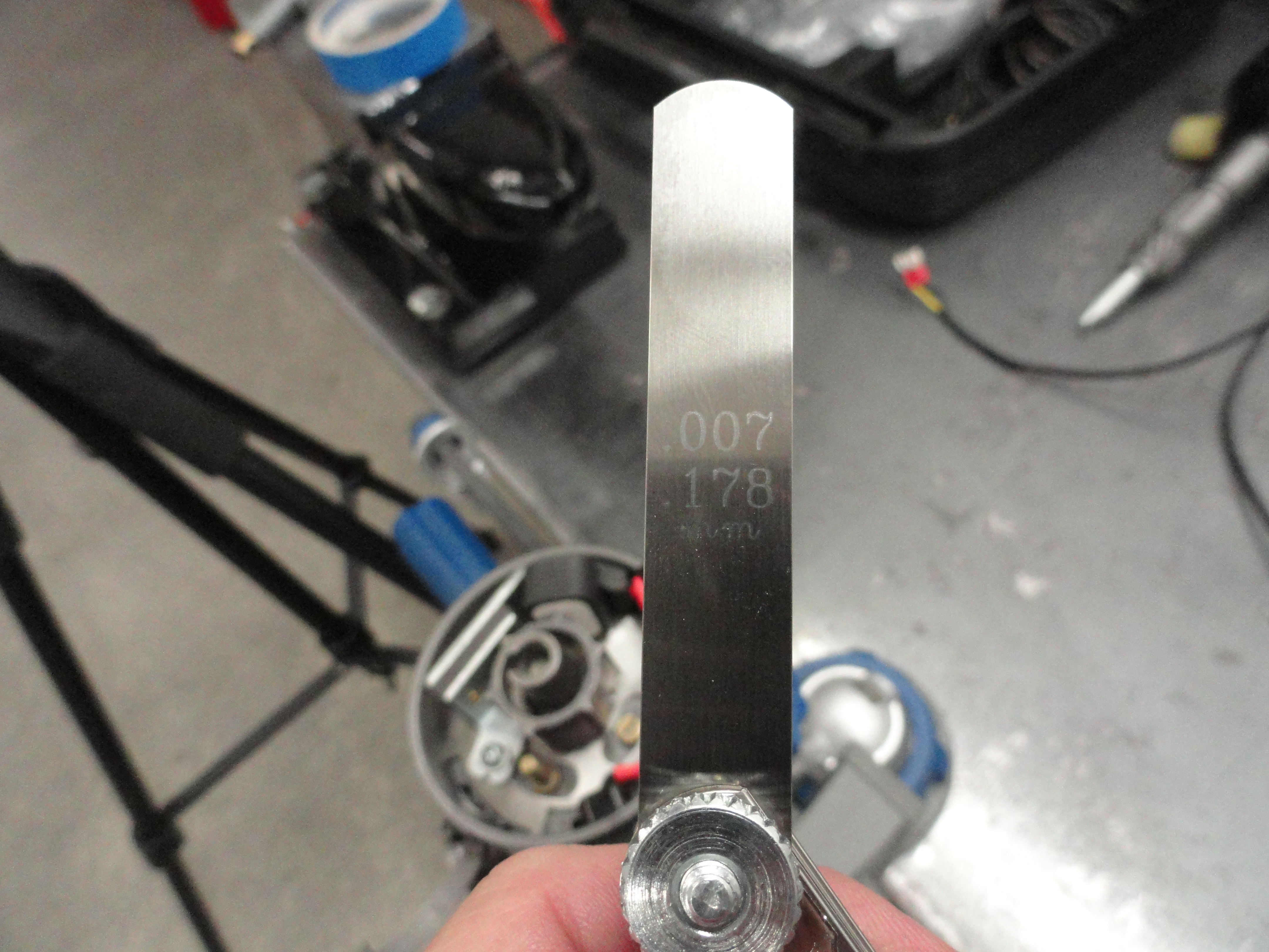
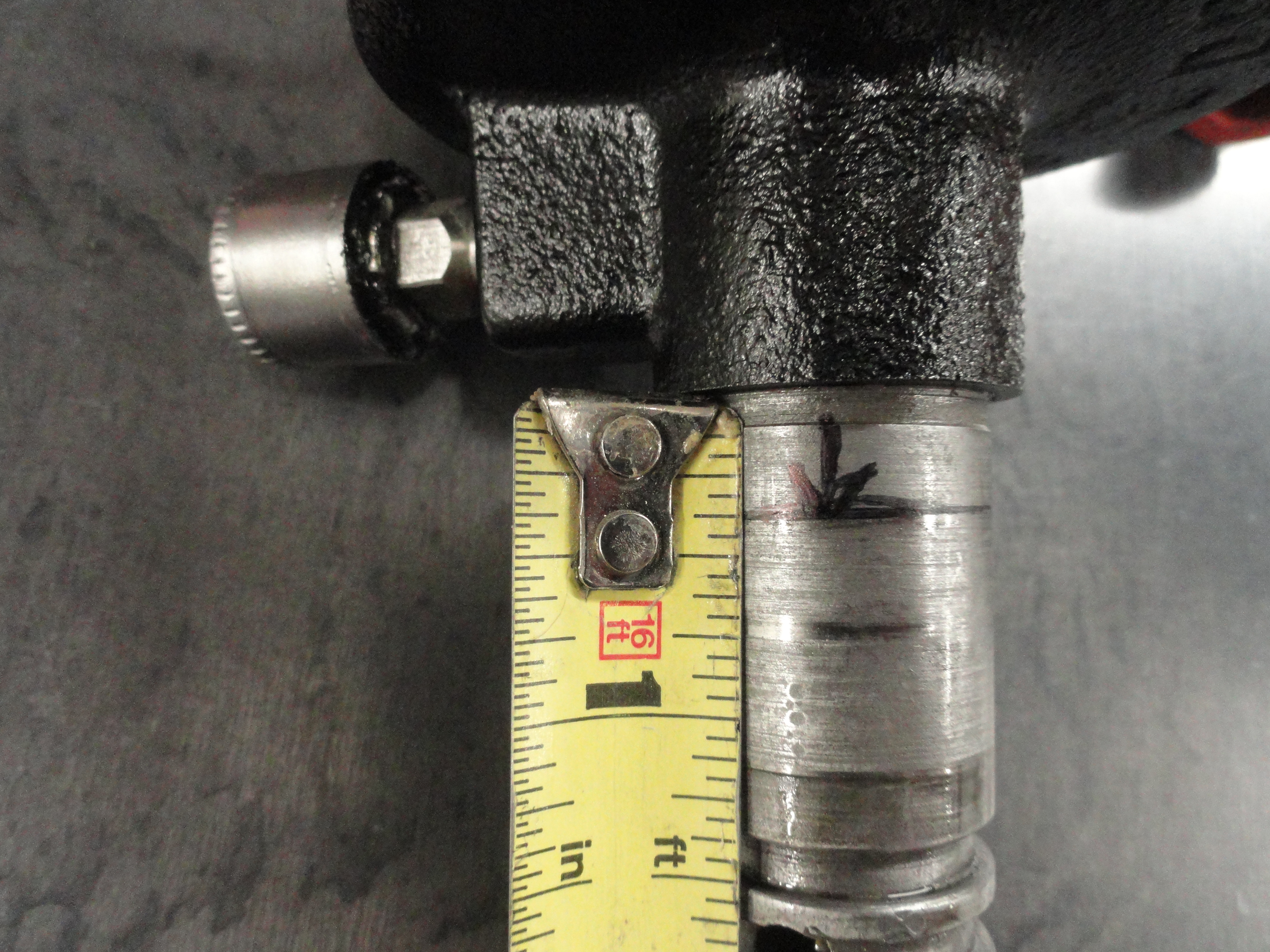
Adjust the Gap To do this, you will need to turn the Distributor shaft so that the lobes on the reluctor PERFECTLY coincide with the pickup on the adapter plate. Loosen the Reluctor Pickup screw with the elongated hole and slowly and carefully move the Reluctor so that it is gapped to .007. This is a VERY tight gap and will require some patience. Check all 6 lobes by turning the Distributor shaft through all 360 degrees. .006 to .009 is okay. This has to do with a common problem with the design of the Distributor. The shaft and shaft housing wears just a little causing this gap problem. Do not sweat it, the system is very forgiving. If you need to loosen the set screws on the Reluctor to center it better, do so. Take the time to get the best gap possible. Turn the Distributor shaft and check for any moving parts rubbing or grinding. There should be NO sounds or evidence of this! Spin the shaft as fast as you can and listen to make sure everything is smooth.
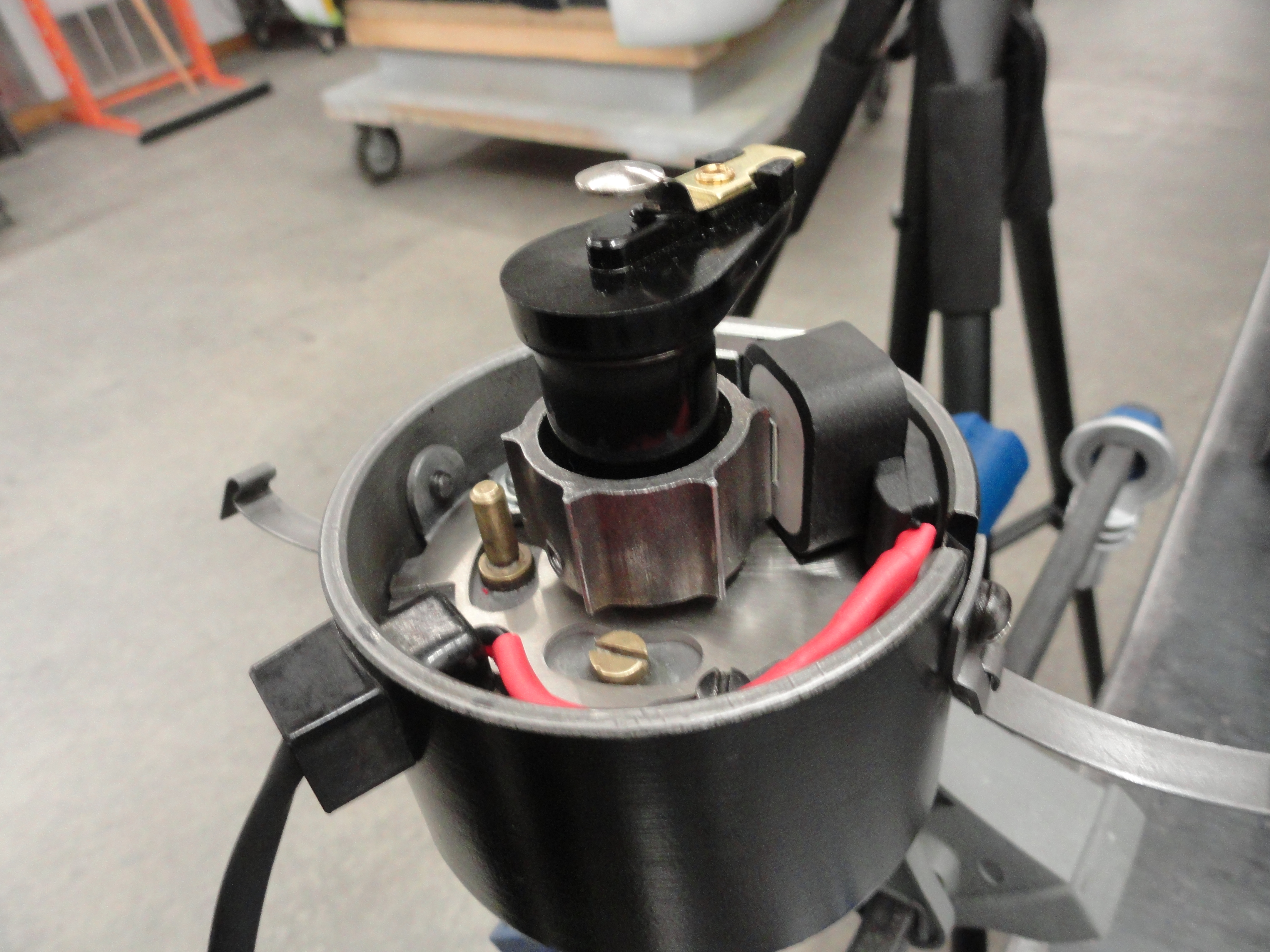
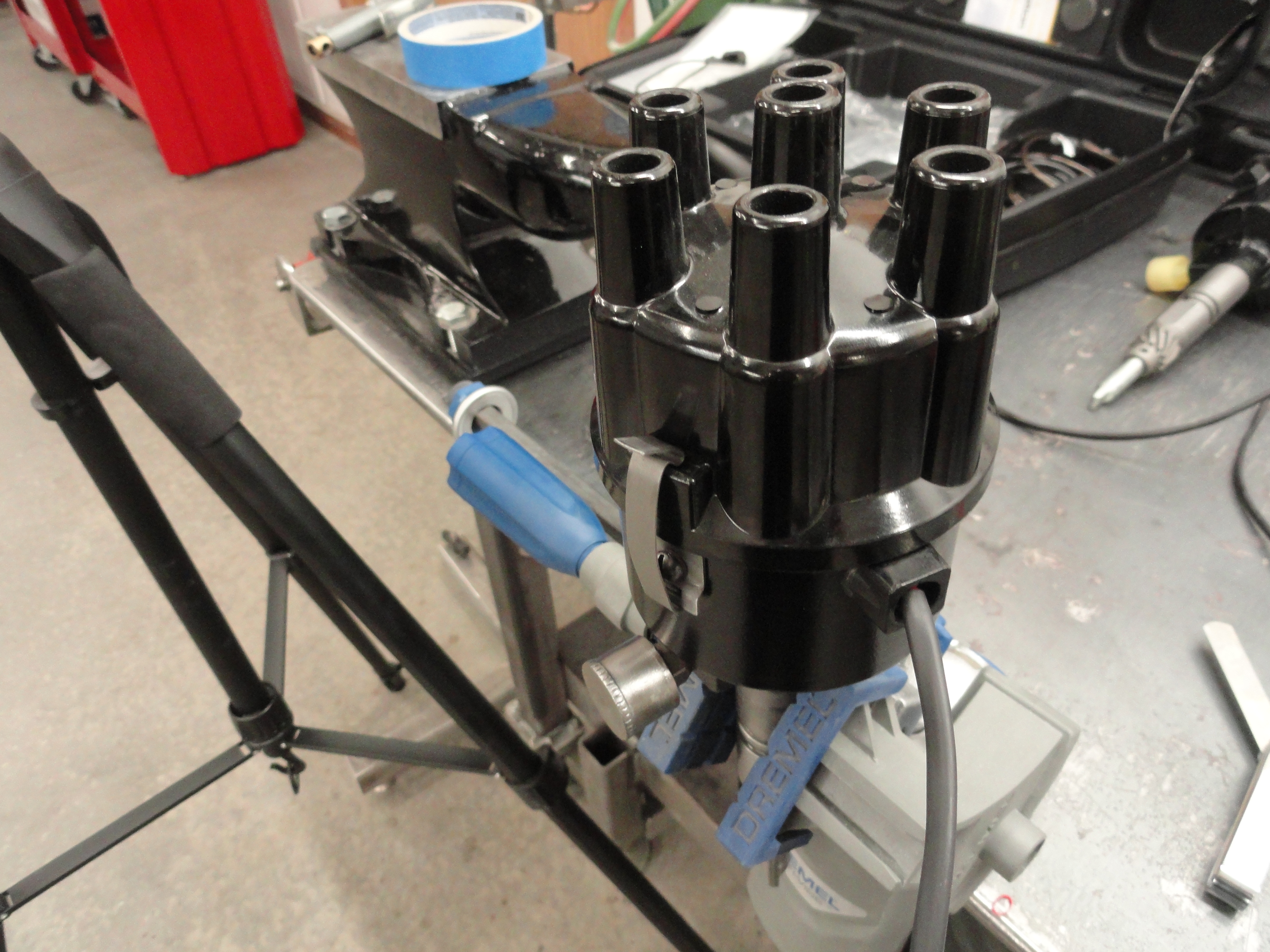
Install the new Rotor and Cap If everything above went as planned, you have plenty of room to drop the rotor in the same way you did before. Place the cap over the assembly making sure the rotor is fully seated and the cap is oriented so that the caps key is in the proper place. If everything went as planned, the cap will seat down nicely and clip in place. The cap has been slightly modified to clear the new Reluctor Pickup. Grinding these features will have no affect on operation of either stock or HEI systems. With the Cap installed, check one last time to make sure no moving parts are coming into contact with each other. Listen carefully. You should hear if anything is not right. Remove the Cap but make sure the Rotor is seated all the way down where it belongs. Set the Distributor Assembly to the side for now.
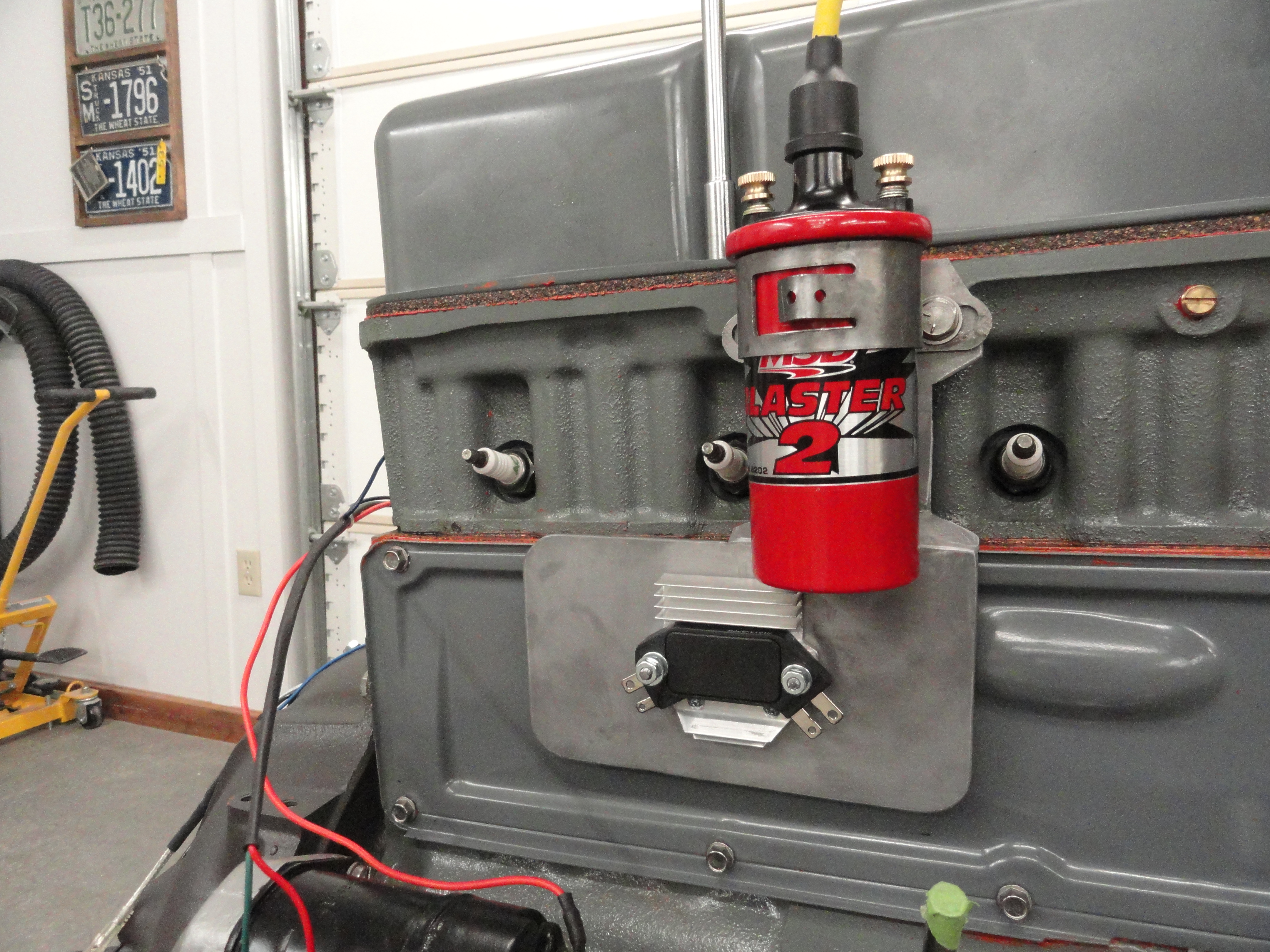
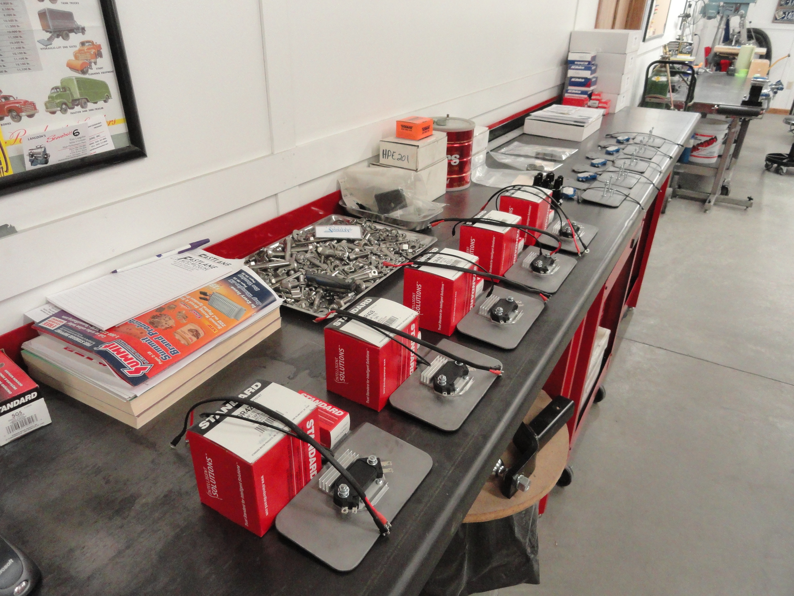
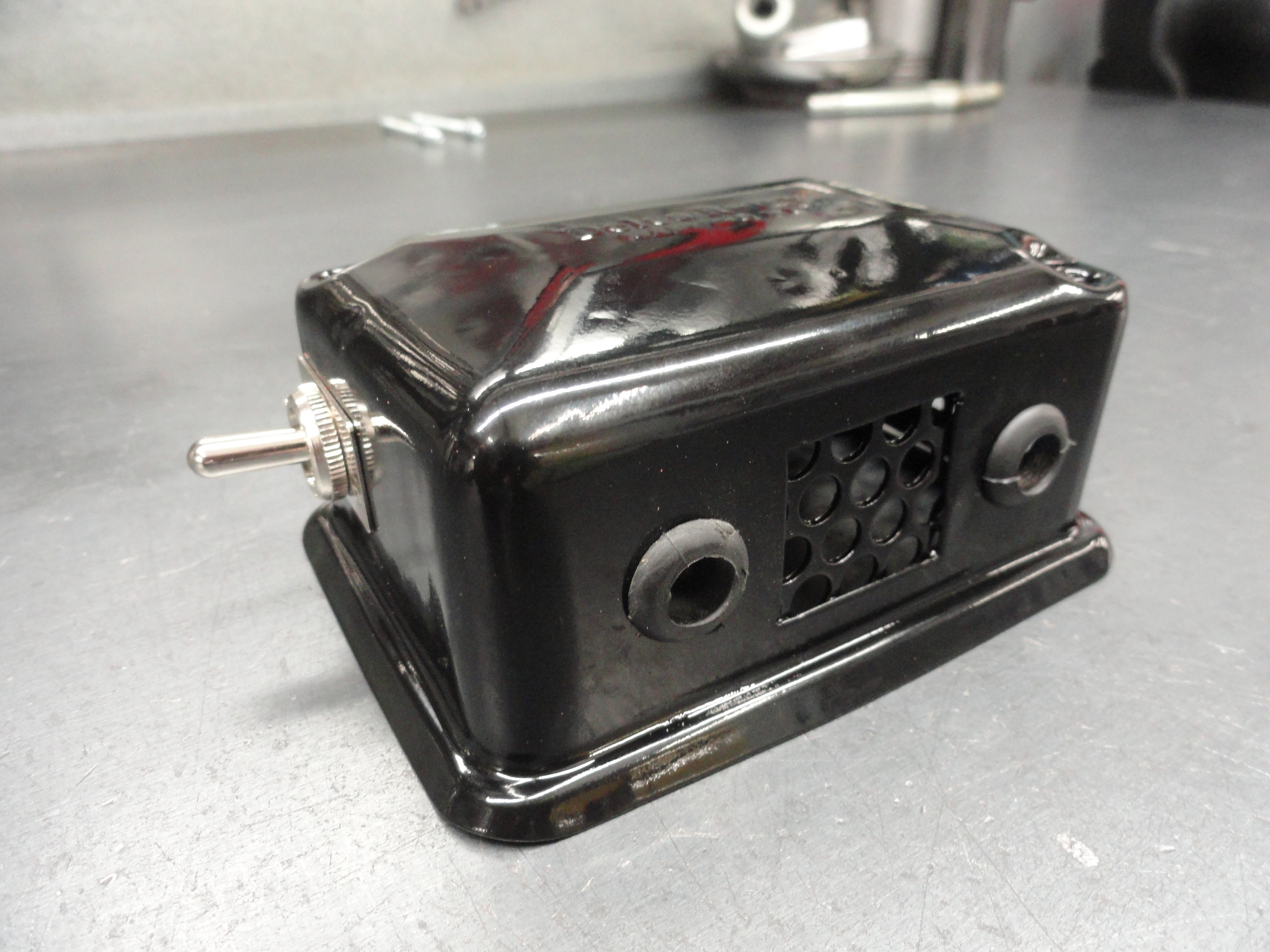
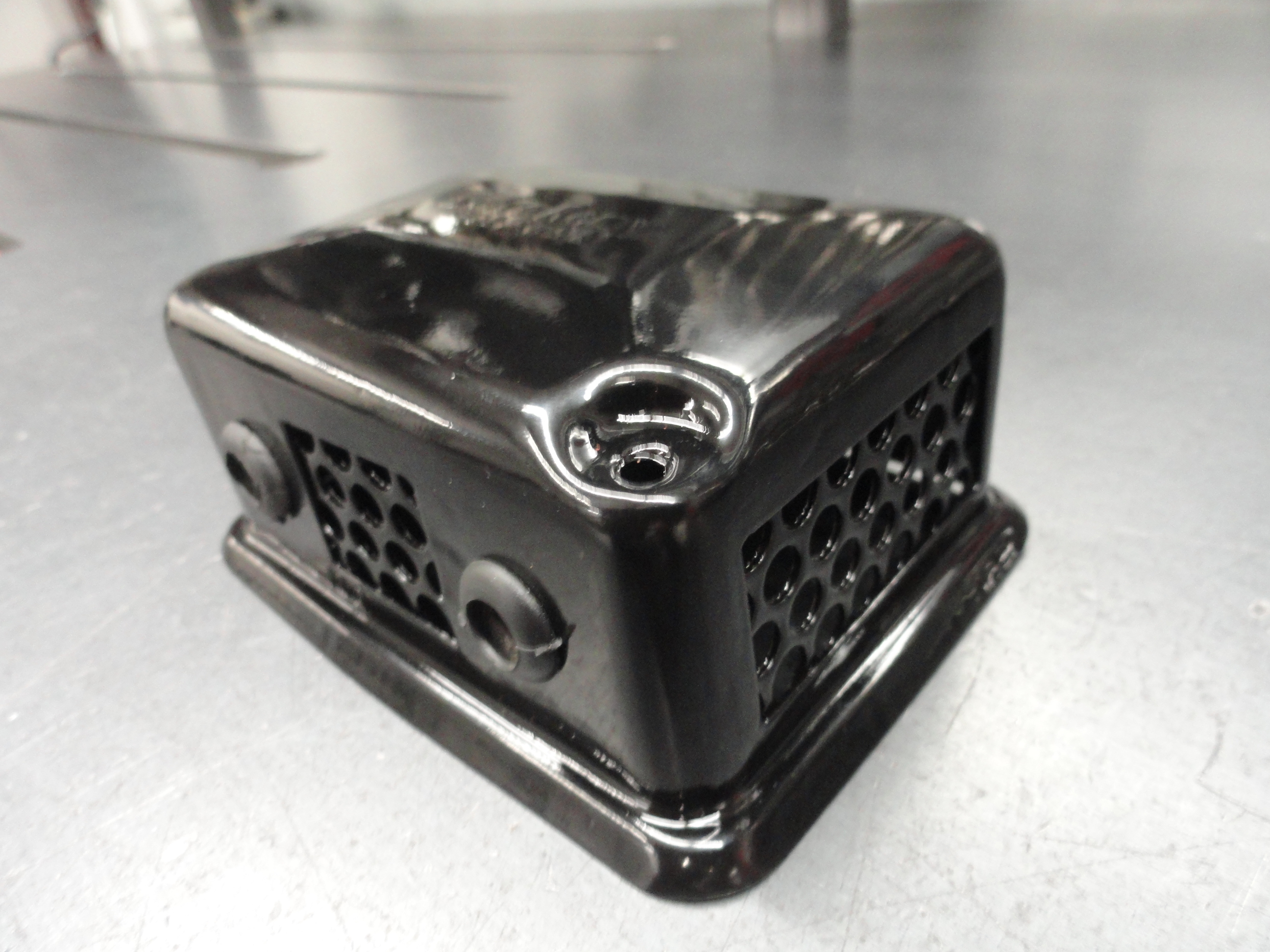
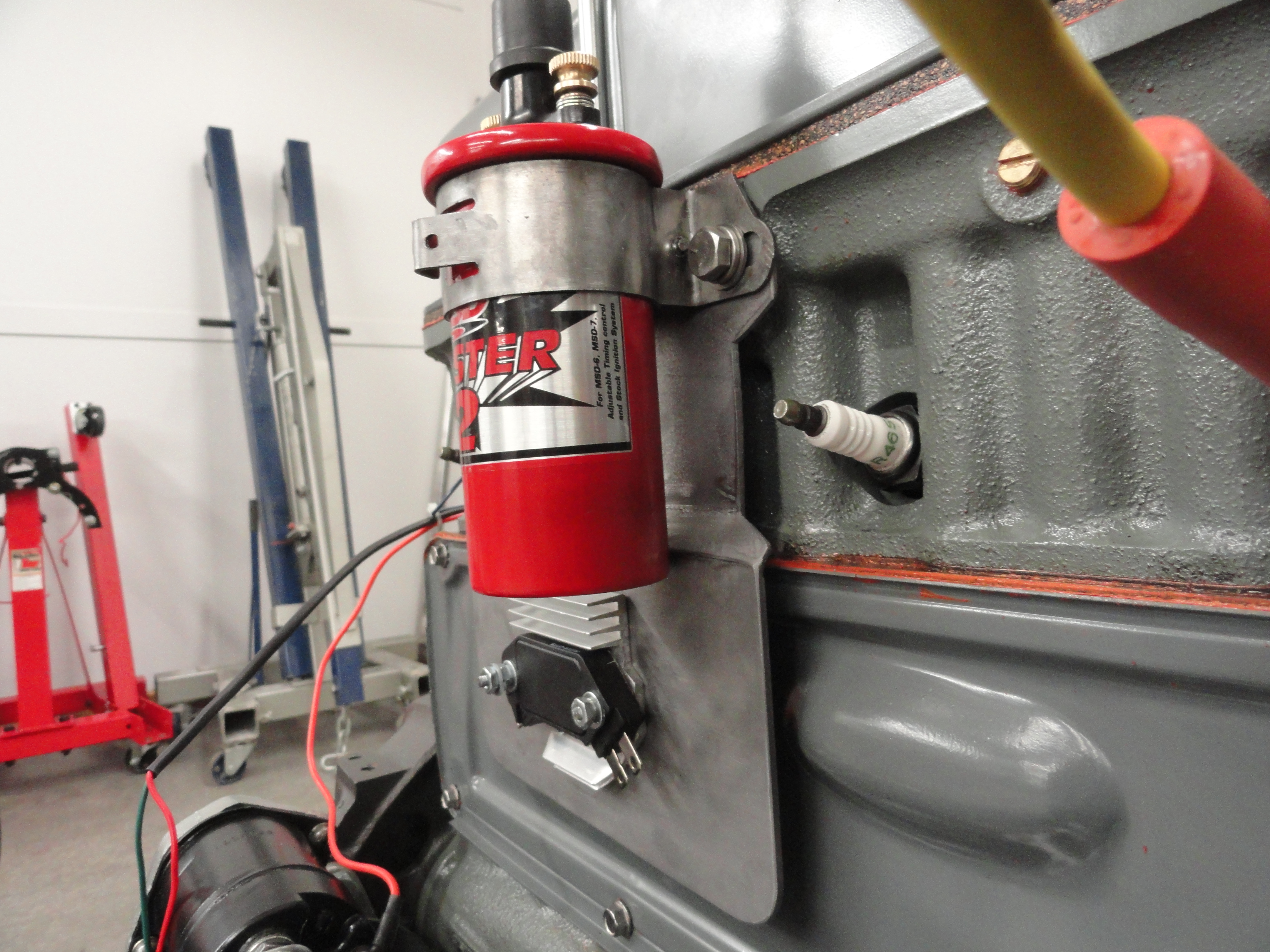
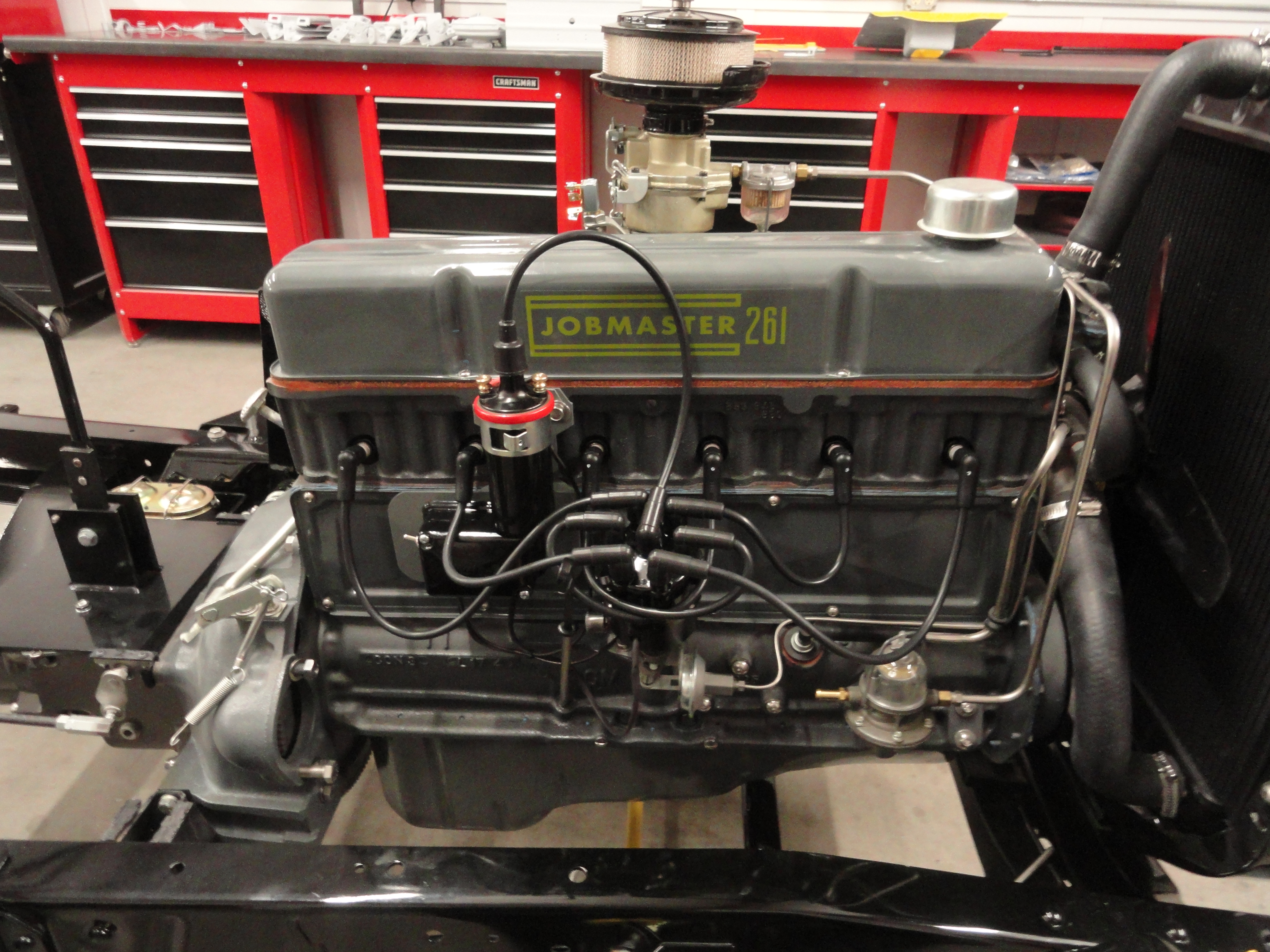
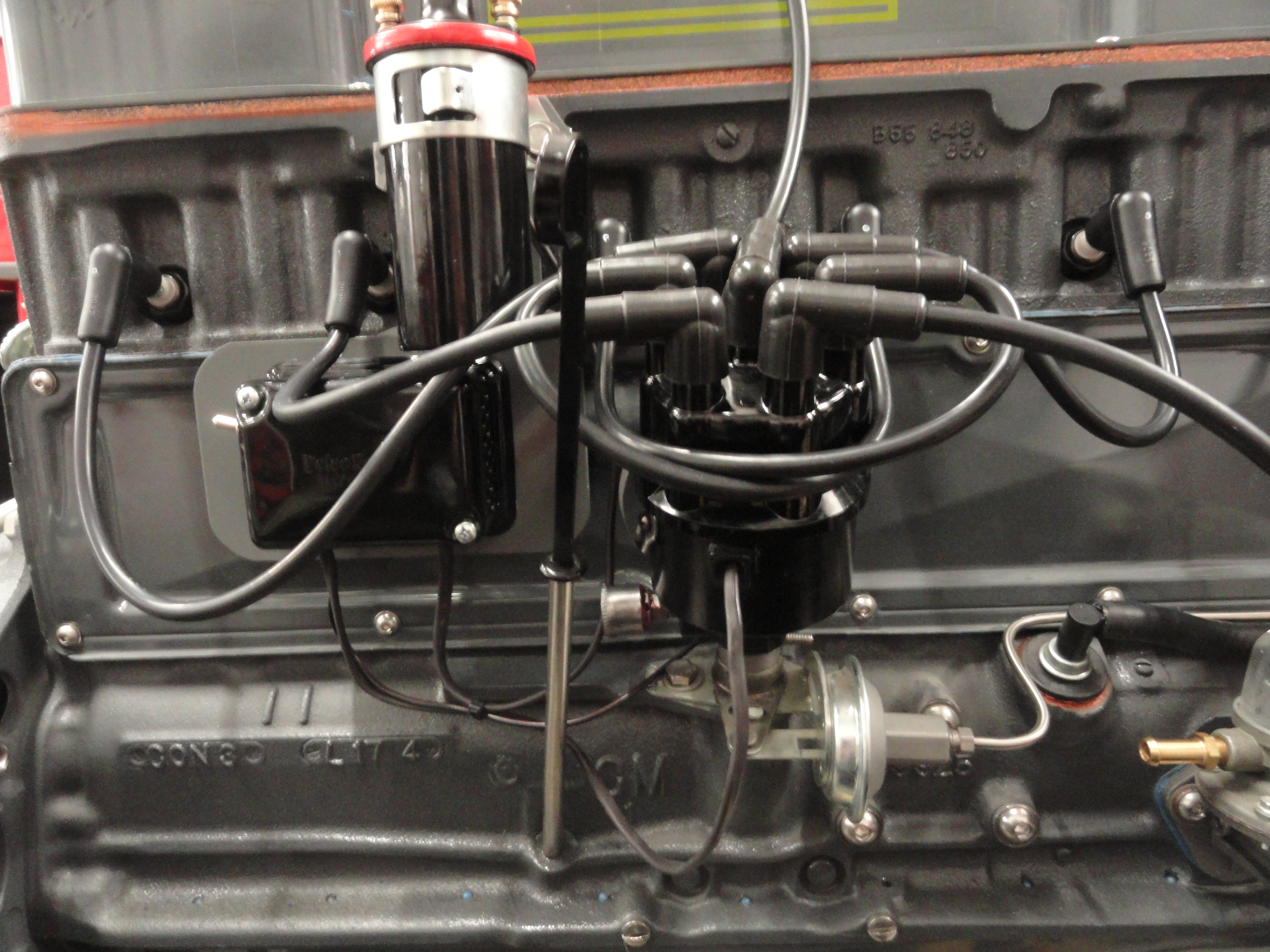
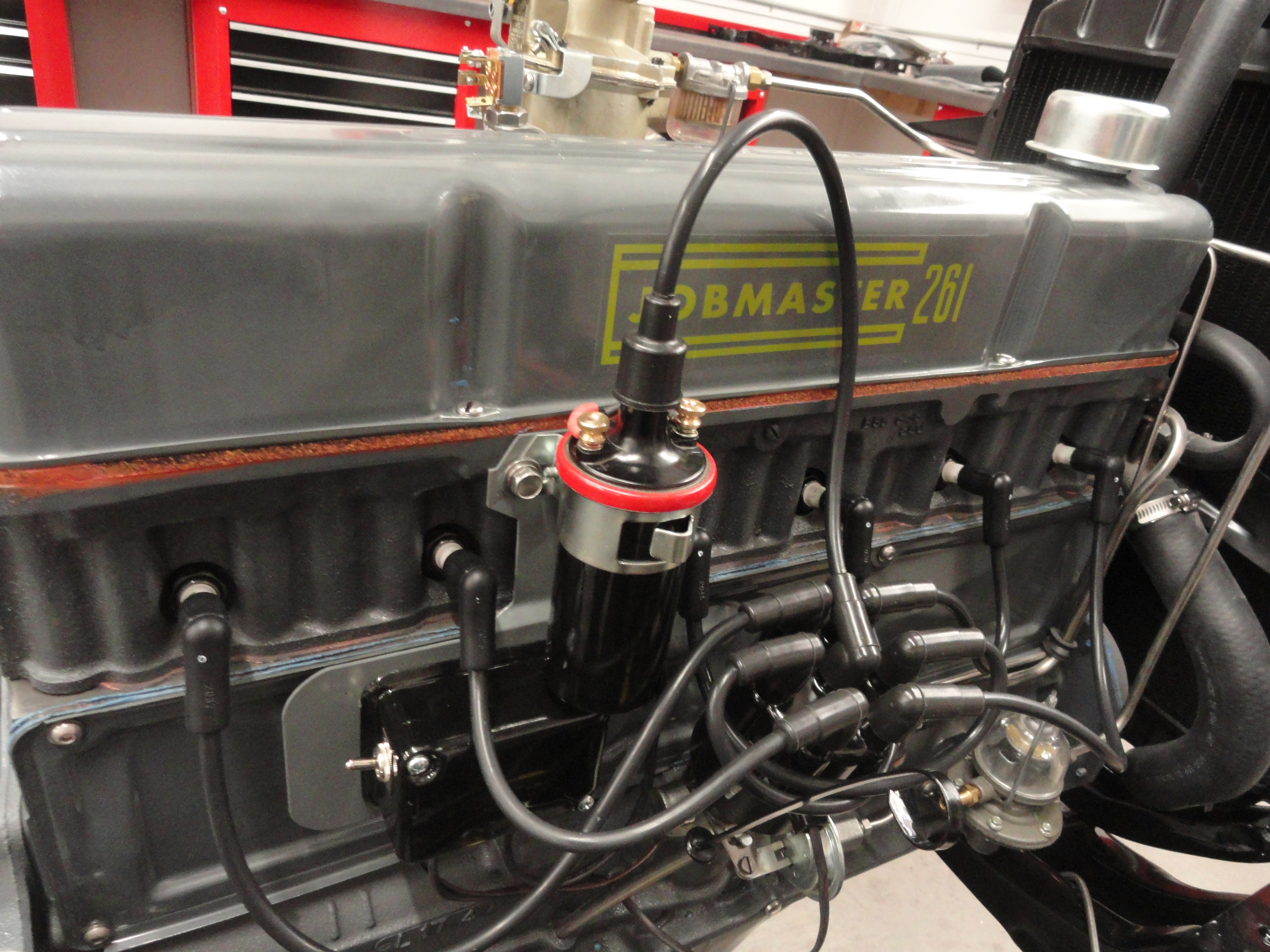
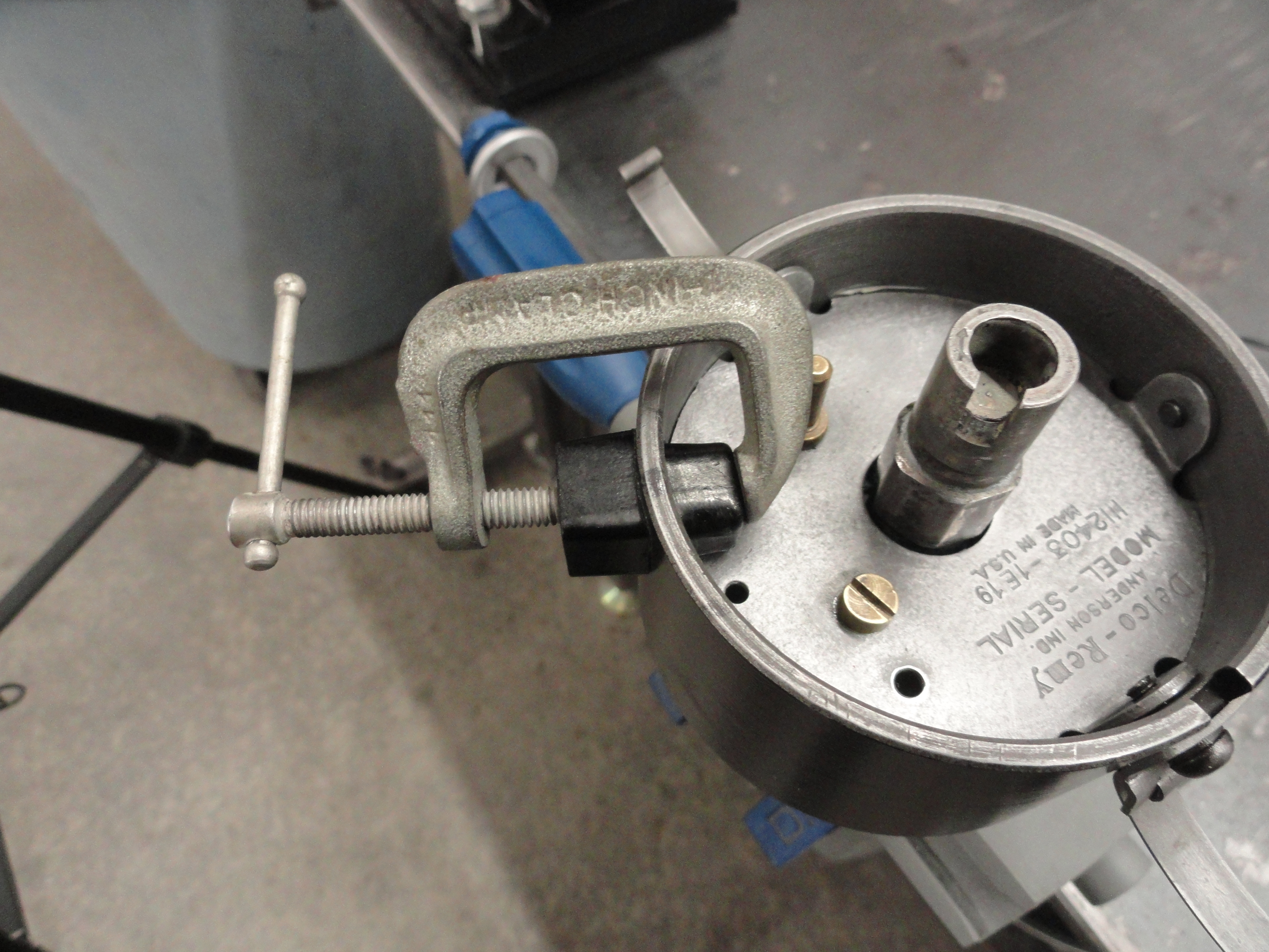
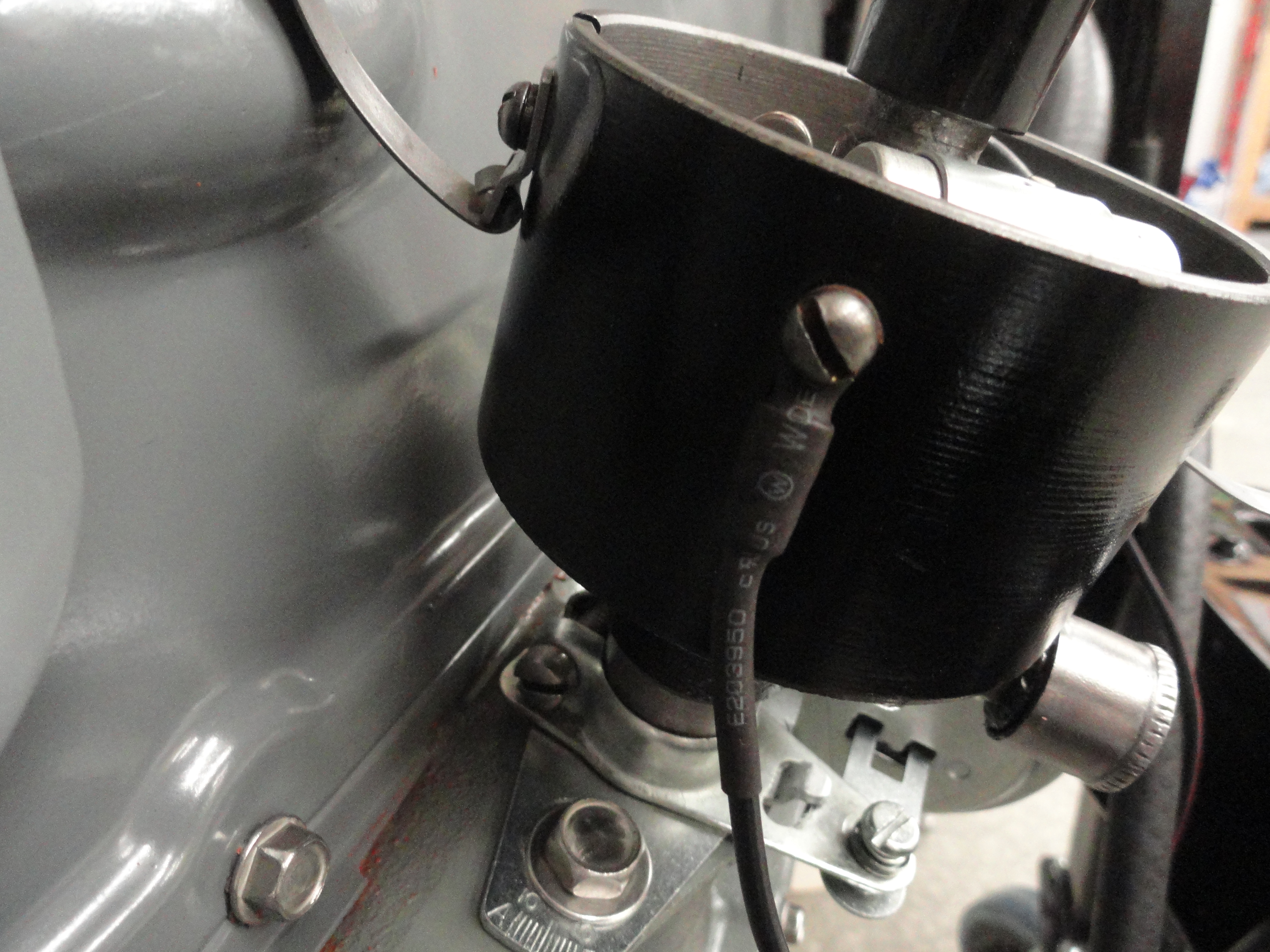
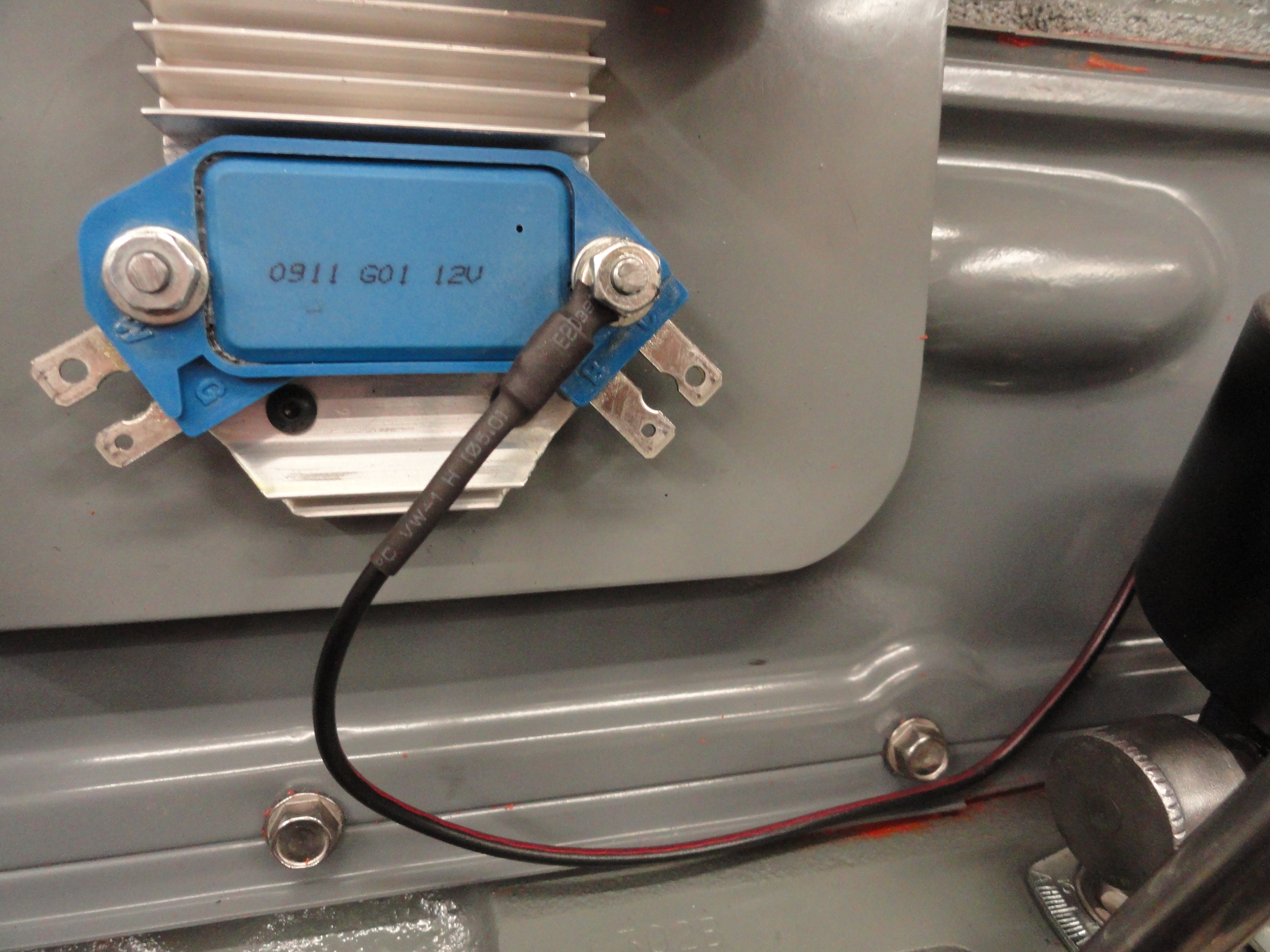
With your Distributor completely squared away, it's time to decide where you want to place the brains of the system, the GM HEI Module and Heat Sink. It could mount to the inner fender or firewall, however, the included solution is better for a few reasons. It places the module and heat sink in the engine's cooling fan air stream, it is very close to the Coil and Distributor thus keeping the wires short for less resistance, and it uses normally unused space. If you get creative, you might use the cover of an old Delco-Remy Regulator and open it up by adding screens to the front and bottom and maybe even put an Ignition Kill Switch on it..
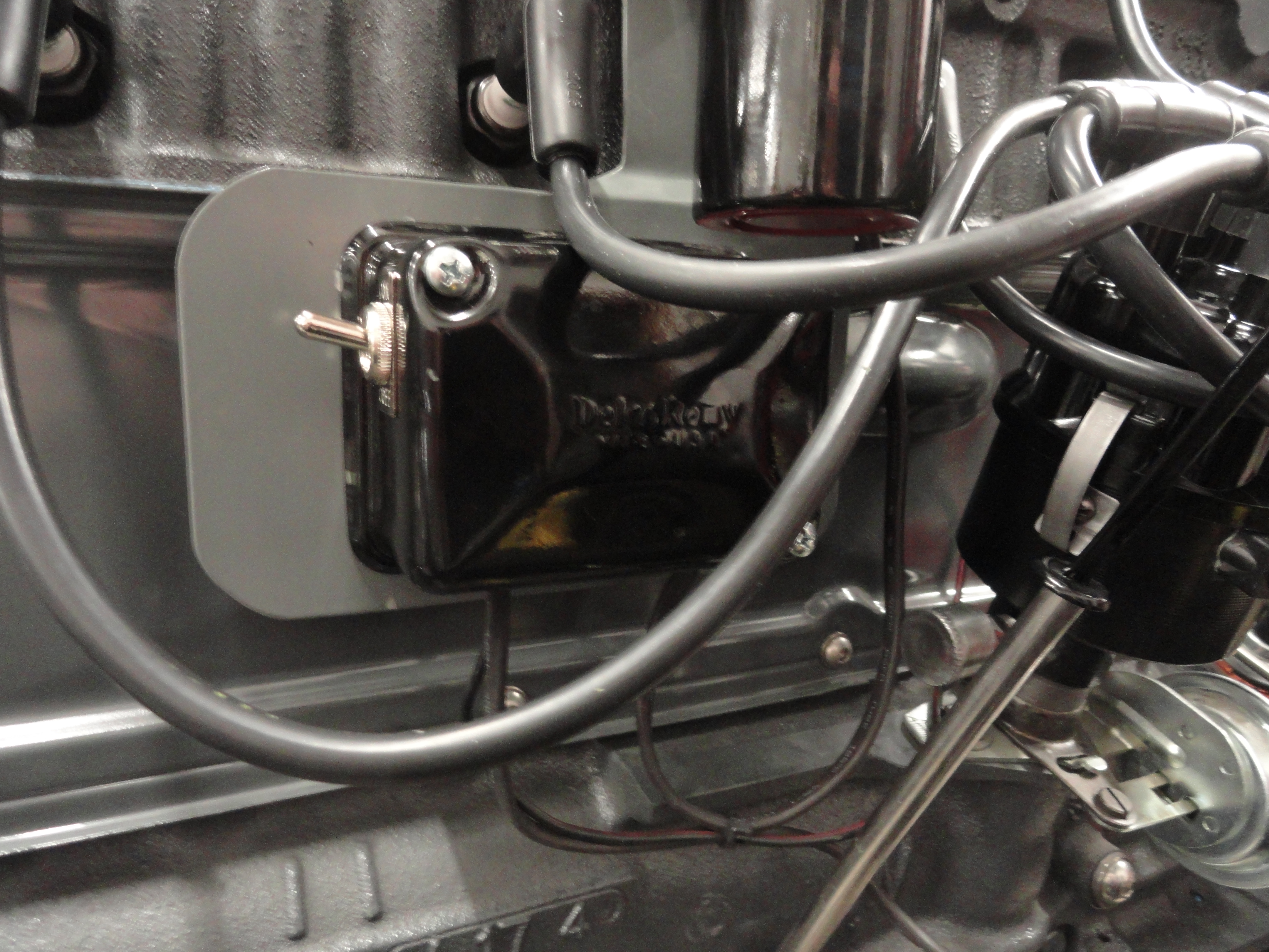
This new mounting plate comes unpainted and you need to paint it yourself. This is to eliminate the argument of what color, what primer, etc, etc. A good engine paint will last and you want to tape off the heat sink before painting. DO NOT remove the heat sink. It needs bare metal below it for good heat dissipation and grounding. The kit comes with the heat sink and module assembled. It has a quick change feature so you can remove and replace the Module from the front without removing the plate. Mask around the heat sink without removing it since there is heat sink compound involved and we want a good heat transfer as well as grounding.
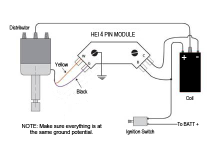
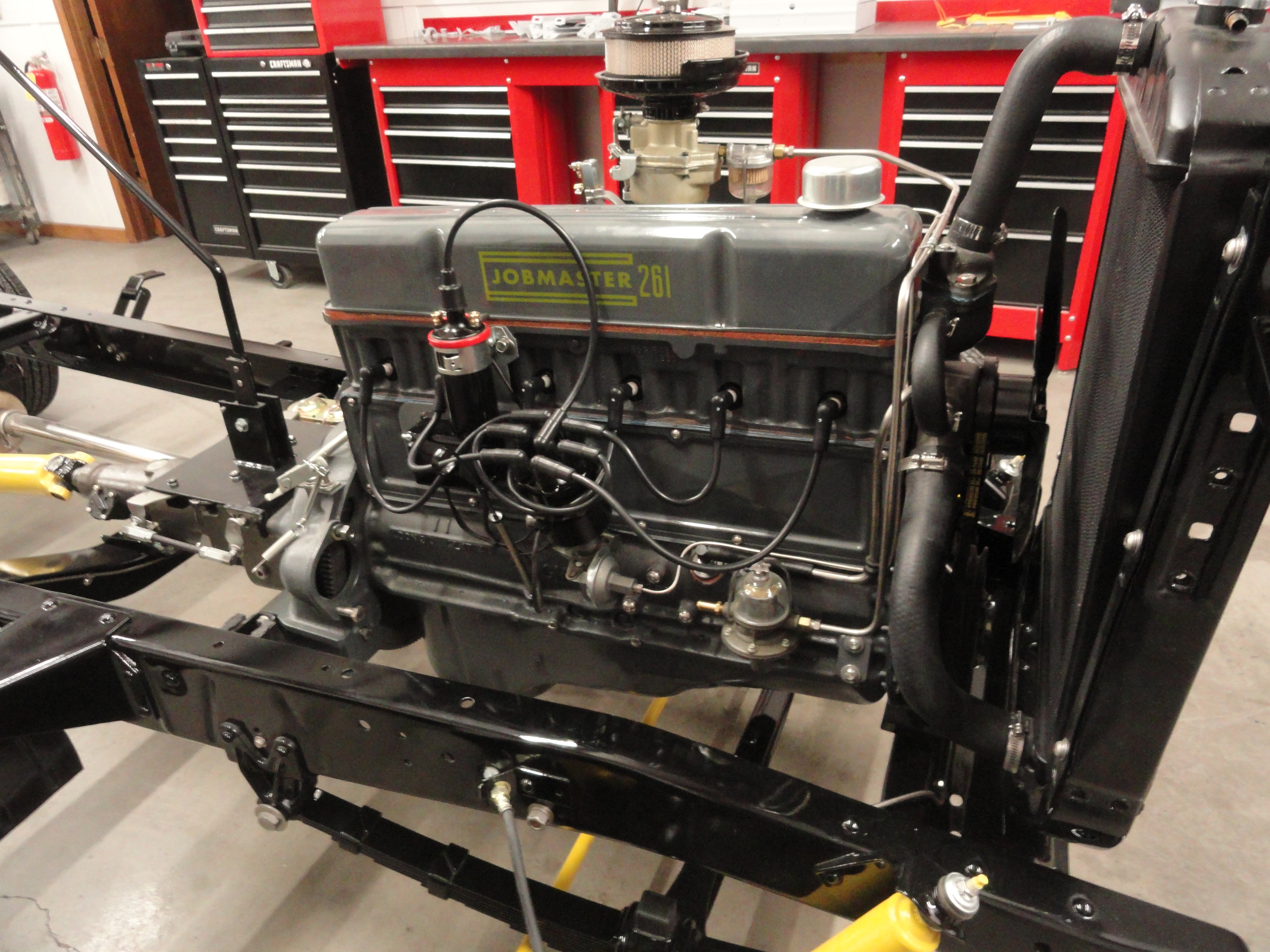
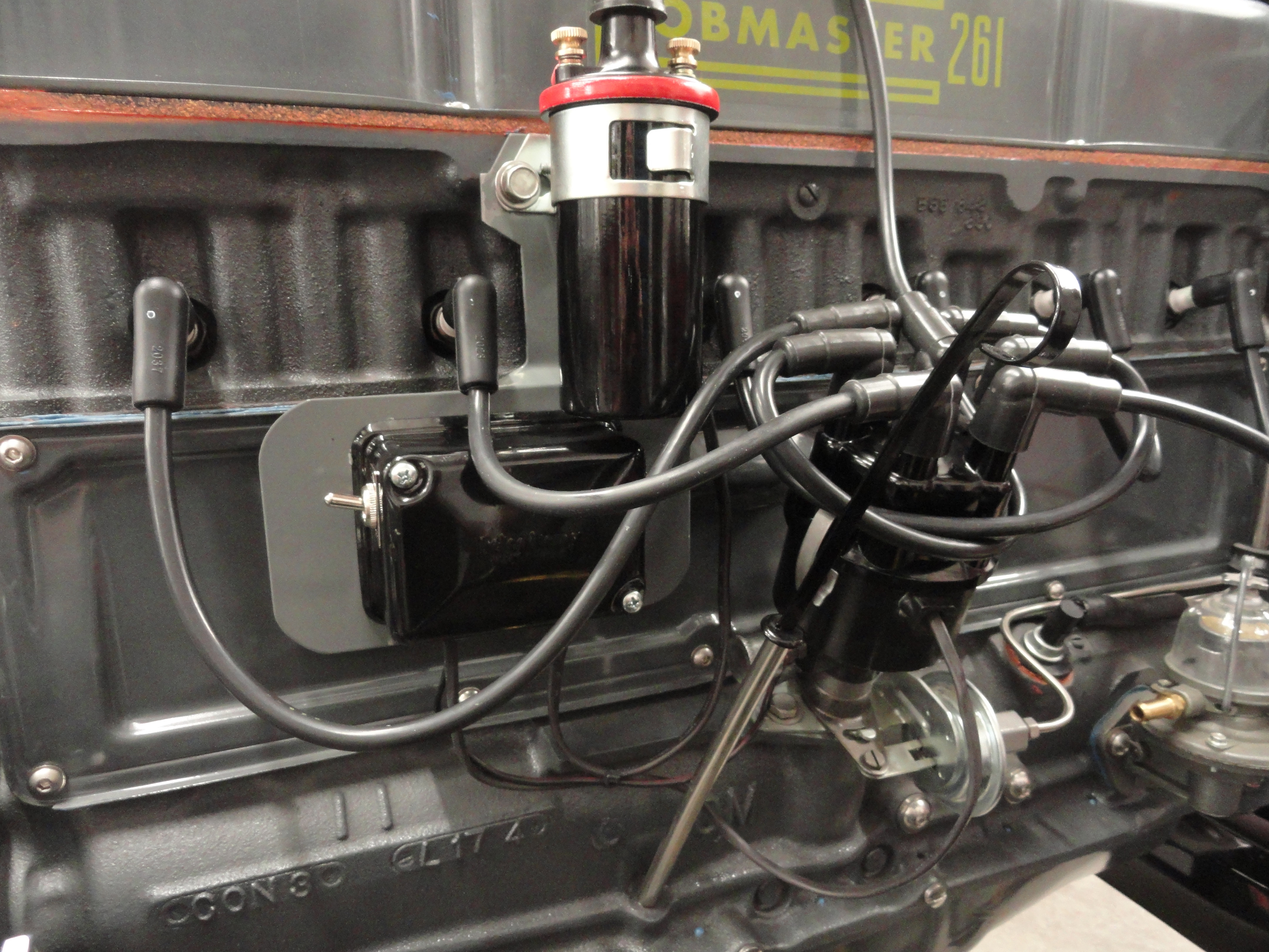
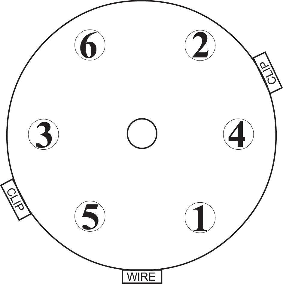
Connect the wiring per the diagram, connect the two wires from the coil to the HEI module and the two wires from the distributor to the HEI Module. The coil wires are Red and Black. Red on the plus side of the coil, Black on the negative side of the coil. Red to the Letter B marked in the HEI module and Black to Letter C marked on the HEI Module. The Yellow wire from the Distributor to Letter W on the HEI module, the Black wire on the Distributor to Letter G in the HEI module.
Your existing red coil wire also goes to the plus side of the coil as usual. This is your ignition wire. You want to bypass your ballast resistor. The new system favors lower ohm values. A small 10 gauge jumper wire across the two resistor terminals will work nicely. This is not included in the kit. Be sure to go over your wiring from the battery, to the ignition switch and from the switch to the coil to ensure you have good properly gauged wires for this purpose. If you are re-wiring these sections for this, err on the side of caution and use 12 gauge wiring. Since the ballast resistor is not required for HEI, it can be removed, or jumpered. You can connect the two wires (connected to the ballast resistor) together. If you want this reversible so you can go back to points, keep this in mind.
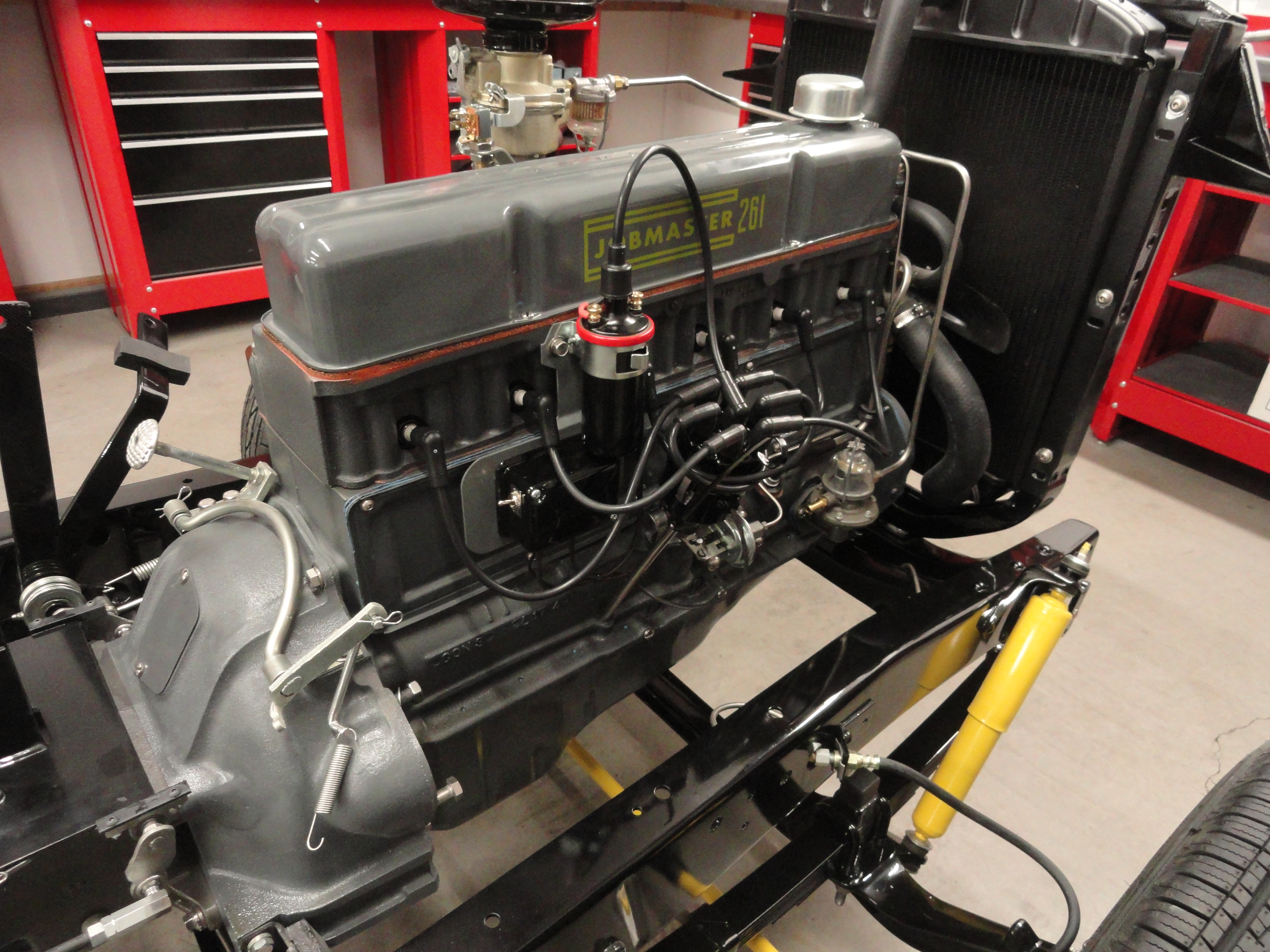
Install The Distributor Remember that diagram you made to ensure you knew the exact direction the rotor is pointed and the exact direction the clips and
wire conduit are pointing? Now is when we use them. Point the rotor to the place it was turned when you removed it, with the body of the Distributor oriented as
it was and insert the Distributor in the hole. Push it down and as you push it, the rotor should turn to the exact same place it was pointing when you first
removed the cap. YOU ARE NOT DONE YET! To the right is the typical orientation of the Distributor, however yours may vary.
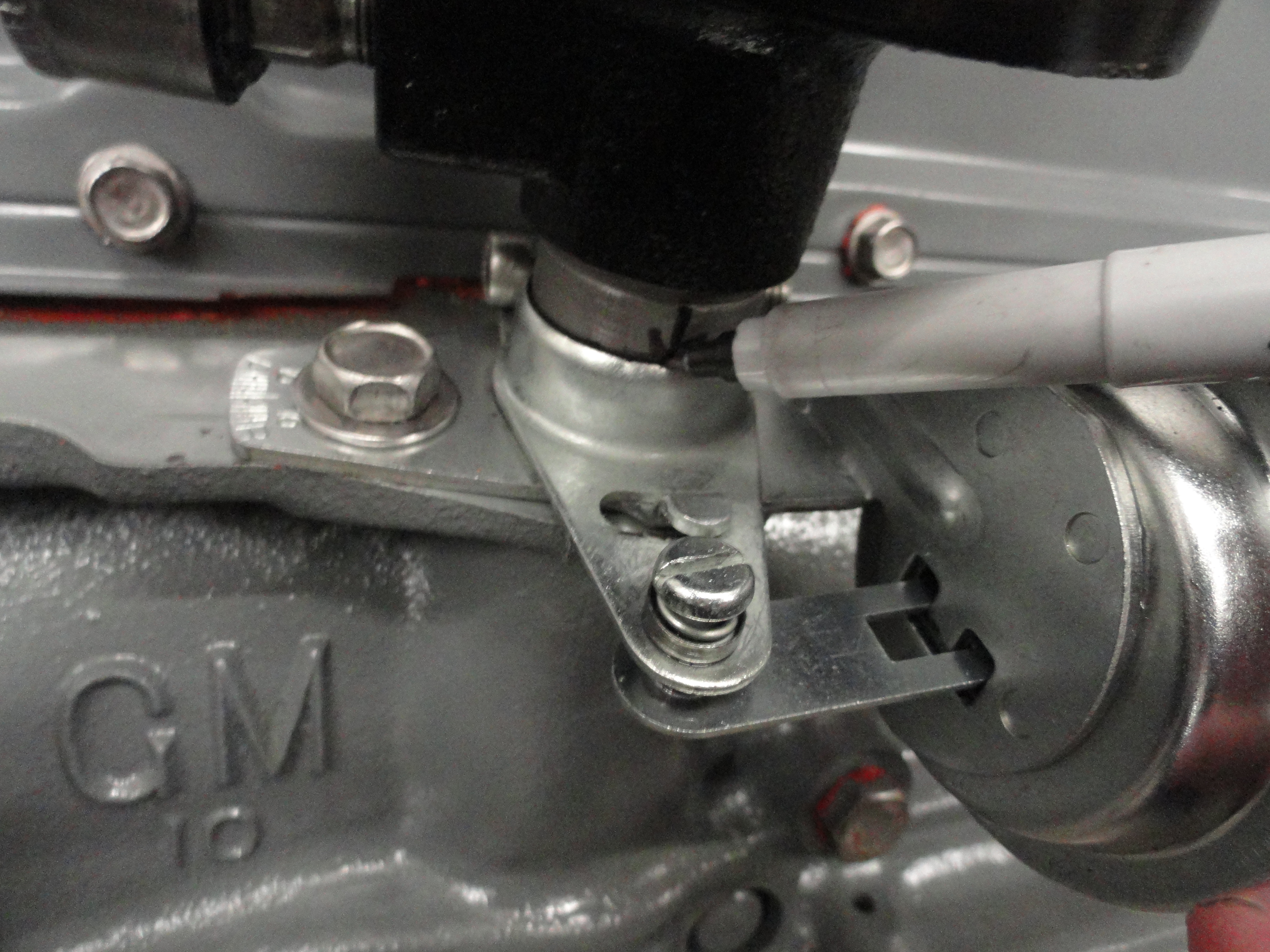
This is the dangerous part and you WILL ruin your engine if this is not done right. Make sure it 'clicks' into place and seats all the way down inside the oil pump. Look carefully at what is left of the shaft that didn't go down the hole... the area between the top of the Vac Advance Clamp and the top of the shaft. If there is roughly 1/2" it is NOT down all the way. If you see 3/8" or less it could be all the way down. Once you are sure it is ALL the way down, tighten the clamp securely with the clips and conduit pointing in the proper direction. You can lift and push down, lift and push down, etc. a few times and it should click into place. If you have never done this before it can be daunting, but be patient and it will all come together. If you give up and decide it's not going down all the way due to the oil pump slot being turned slightly wrong, as a last resort, turn it a little with a long screwdriver and try again until it seats properly. Connect the two wires coming out of the Distributor per the schematic. If you get it down to the mark you made previously, you are good to go, but check oil pressure on startup anyway!
Timing the Engine Since the rotors position never changed, you are in the ballpark already. If the engine does not start right up the first time, loosen the screw at the back of the distributor mount and turn it one way a few degrees, if that doesn't do it, turn it the other way a few degrees. Follow standard ignition timing procedures with your timing light to get things where you want them. Follow common troubleshooting procedures if there is a problem. If you followed the above instructions on gapping, placement and wiring it should easily start right up the first time. Timing should not be any different than your stock system, just more precise. By installing this kit, you WILL have changed your timing slightly, so expect to have to make some adjustments. This is a great time to check your valve adjustment, Ignition Timing (turning the distributor to meet the BB on the flywheel or where-ever it runs best for you), and your idle mixture screw for optimum performance. Things you will never have to do again, is concern yourself over dwell and points gap adjustments. The computer knows what the engine needs. The last thing you need to do is take it for a test drive and make your timing adjustments accordingly, then, when you have it all timed, email deve@speedprint.com and let me know how you feel about the instructions given, the kit, and your feeling on how your vehicle runs after. Very important I get feedback!
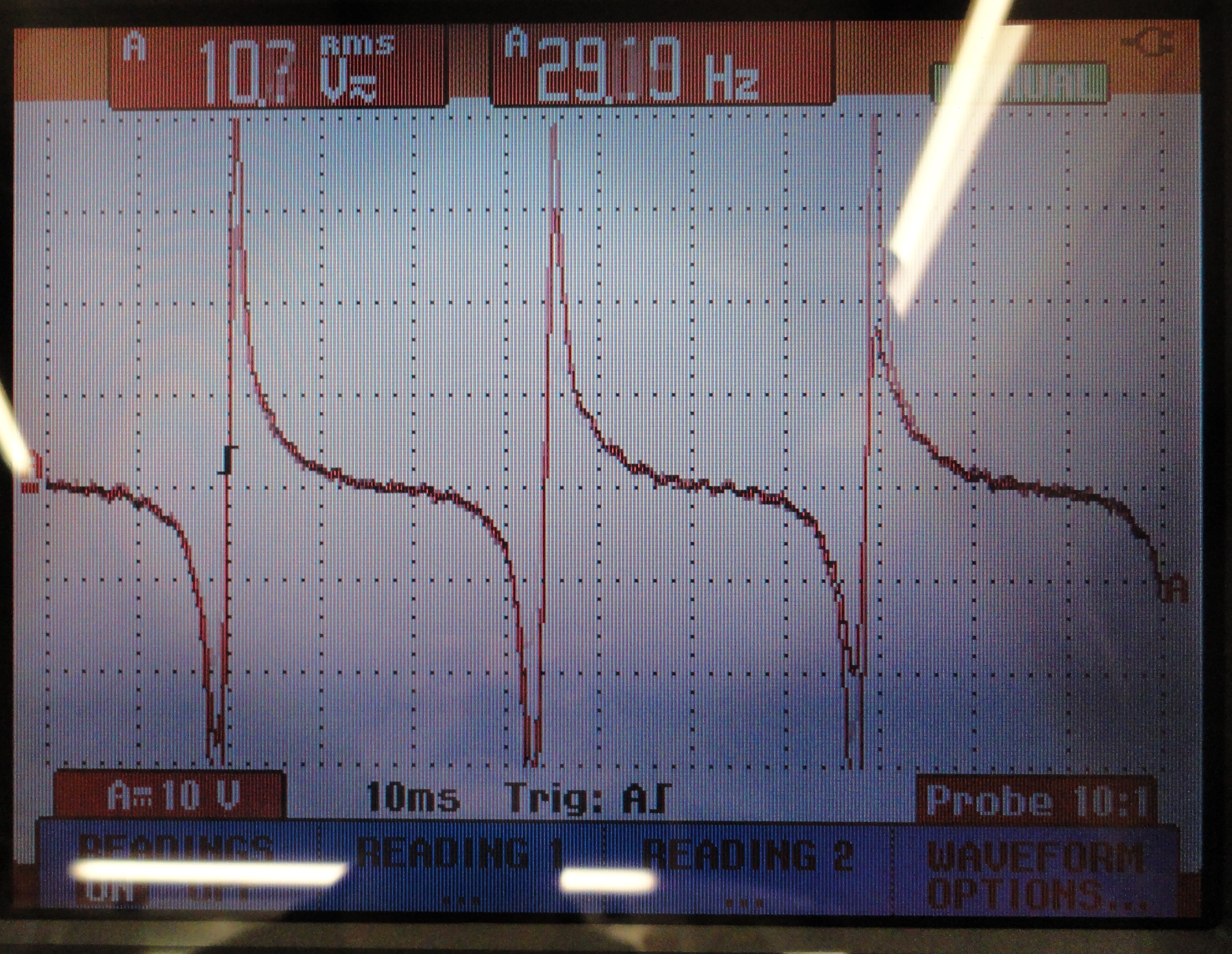
If you want the ignition system installed and tested, we can do that for you! This includes testing the distributor in our test engine to ensure it works exactly as it's supposed to. It also comes with a printout of the Oscilloscope triggers from the distributor during testing. There are two levels of services available:
This is a simple setup that doesn't require adjustments or maintenance to the actual parts. They either work or they don't. There are two items in the system that could go bad over time. Since there are two, let's take one of them out of the equation. They are the GM HEI Module that is mounted to the external mounting plate, and the internal (to the Distributor) Reluctor Pickup. They are the only two things that can possibly go bad. So, to take the Internal Distributor Reluctor Pickup out of the game, with a Digital Multimeter set to LOW Ohms, measure across the two leads that are connected to the GM HEI Module. Disconnect them first. Your reading for a good Reluctor Pickup should be between .200 and .400 ohms. If you have that, and your system has been running great until then, it is the GM HEI Module. This is a VERY reliable system.
If your engine runs, but very poorly after the install, chances are pretty good that all you need to do is swap the two wires on the left of the ignition module. Meaning, the yellow wire and black wires need to be exchanged with each other. This is because Standard Motor Products does not QC them and one batch may be one way, another batch the other.
If something happens that you didn't mark the Distributor Rotors placement before removing the Distributor, or feel suspect that maybe you didn't get it installed properly, check out this How-To (you will be glad you did): Stovebolt Timing Explained!
If you wish to save money and do a complete Distributor rebuild yourself, check out the article here:
The Distributor Start to Finish
If you wish to make all of this HEI modification yourself, check out the article here:
HEI For Your 1940-1962 Chevy 6 Cylinder
We are not in this for the money, we just want you to be satisfied with the end result!
We are developing more fun stuff for your engine. The Kits that are available now are Regular and Deluxe PCV Upgrade Kits, Spin-on Oil Filter Adapter Kits, and of course our popular HEI conversion kit. Check out all of our offerings at Farm-it-Out!
Maybe some of these will help with your installation...